EP1302388A1 - Vehicle hood assembly for pedestrian protection - Google Patents
Vehicle hood assembly for pedestrian protection Download PDFInfo
- Publication number
- EP1302388A1 EP1302388A1 EP01124637A EP01124637A EP1302388A1 EP 1302388 A1 EP1302388 A1 EP 1302388A1 EP 01124637 A EP01124637 A EP 01124637A EP 01124637 A EP01124637 A EP 01124637A EP 1302388 A1 EP1302388 A1 EP 1302388A1
- Authority
- EP
- European Patent Office
- Prior art keywords
- hood
- assembly according
- hood assembly
- lifting device
- vehicle hood
- Prior art date
- Legal status (The legal status is an assumption and is not a legal conclusion. Google has not performed a legal analysis and makes no representation as to the accuracy of the status listed.)
- Granted
Links
- 230000005540 biological transmission Effects 0.000 claims abstract description 12
- 238000001816 cooling Methods 0.000 claims description 14
- 238000006073 displacement reaction Methods 0.000 description 4
- 230000002950 deficient Effects 0.000 description 1
Images


Classifications
-
- B—PERFORMING OPERATIONS; TRANSPORTING
- B60—VEHICLES IN GENERAL
- B60R—VEHICLES, VEHICLE FITTINGS, OR VEHICLE PARTS, NOT OTHERWISE PROVIDED FOR
- B60R21/00—Arrangements or fittings on vehicles for protecting or preventing injuries to occupants or pedestrians in case of accidents or other traffic risks
- B60R21/34—Protecting non-occupants of a vehicle, e.g. pedestrians
- B60R21/38—Protecting non-occupants of a vehicle, e.g. pedestrians using means for lifting bonnets
-
- B—PERFORMING OPERATIONS; TRANSPORTING
- B60—VEHICLES IN GENERAL
- B60R—VEHICLES, VEHICLE FITTINGS, OR VEHICLE PARTS, NOT OTHERWISE PROVIDED FOR
- B60R21/00—Arrangements or fittings on vehicles for protecting or preventing injuries to occupants or pedestrians in case of accidents or other traffic risks
- B60R21/34—Protecting non-occupants of a vehicle, e.g. pedestrians
- B60R2021/343—Protecting non-occupants of a vehicle, e.g. pedestrians using deformable body panel, bodywork or components
Definitions
- the present invention relates to a vehicle hood assembly for pedestrian protection in accordance with the preamble of claim 1.
- EP 1078826 discloses a pedestrian safety module device with a deployable hood. It consists of a tilting cross beam beneath the leading edge of the hood, and a hinge assembly at the trailing edge of the hood, whereby the hood is latched to the cross beam. In case of a pedestrian impact at the leading edge the cross beam is mechanically released to rotate, so that the hood is lowered at the leading edge. Simultaneously the rotational impulse of the hood is used to lift the trailing edge of the hood. A two bar link at the rear hinge assembly is released by the hood impulse and enables lifting of the trailing edge of the hood, and locks the hood in a deployed position.
- the hood is raised at the trailing edge, the forward area of the hood will not raise. To achieve more space between the hood and the engine parts, it is preferred to raise the hood also at the leading edge.
- one or more load transmission means are arranged between the cross car beam and at least one separate lifting device for the hood.
- a movement of the released cross member relative to the body is used to drive one or more separate lifting devices for the hood, whereby the transmission means transfer both movement and a load from the cross member to the lifting devices.
- the hood When a pedestrian collides with the trailing edge of the hood, the hood is subjected to an impact load, which is transferred to the cross bar beam, e.g. by latch means and/or by bump stops.
- the cross car beam is attached to the vehicle body with releasable fixings, so that in case of an overload due to the impact load of a pedestrian the fixings release the cross car beam.
- both hood and cross car beam moves together mainly in the direction of the impact load.
- This movement is used to drive at least one lifting device for lifting the hood by arranging the load transmission means between cross car beam and lifting devices.
- Preferably several lifting devices are arranged at the trailing edge of the hood and near the fixing of the cross car beam.
- the hood assembly according to the invention works completely mechanical without the need of an additional control device, therefore no sophisticated and noisy electronic safety controls are required. Additionally the drive of the lifting device works without stored energy like airbags, pyrotechnic hinges, spring devices or other lifting devices known from prior art. This is a big advantage in so far as after years in service the stored energy may be reduced, e. g. because a spring is corroded, or the stored energy could not be activated, e.g. because of defective contacts in a pyrotechnic device.
- the object of the invention is also achieved, according to another embodiment of the invention, in that a movement of the released cross member relative to the body is used to drive at least one release mechanism of one or more separate lifting devices for the hood.
- the cross member acts in the same way as described in the previous embodiment. The only difference is, that now the movement of the cross member is used to drive any release mechanism of a lifting device.
- the released cross member is guided in an elongated guide.
- the elongated guide can be e.g. a rail or a slotted hole, in which the cross car beam or a part of the cross car beam slides after the impact load has released the fixings.
- the guide provides a defined direction for the movement of the cross car beam, so that the drive for the lifting device can be attached accordingly to the cross car beam to get a maximum of displacement and acting force on the drive.
- the released cross member is guided in a pivot guide.
- the pivot guide can be realised by supporting the cross car beam rotary in the vehicle body or, in conjunction with the previous embodiment, the cross car beam is supported rotary in the elongated guide, so that the cross car beam tilts around the pivot guide axis after the impact load has released the fixings. Also the pivot guide provides a defined tilting of the cross car beam, so that the drive for the lifting device can be attached accordingly to the cross car beam to get a maximum of displacement and acting force on the drive. It should be noted that both elongated guide and pivot guide could be used separate or in conjunction.
- the cross member is pivoted to a cooling pack.
- the task of the cooling pack is to support the cross beam, especially when the cross beam extends in forward direction at the centreline of the vehicle, while at the releasable fixings, located at the left and right ends of the cross bar, the cross bar extends more rearwards.
- the cooling pack is mounted more or less rotary on a lower support beam, for example by fixing the cooling pack with elastic elements to the lower support beam, the whole cooling pack can tilt around the lower support beam.
- the cooling pack and the pivoted cross member builds a two bar link, so that in case of a pedestrian impact both can move and tilt together. By this the tilting of the cross beam during the movement of the cross beam can be defined exactly, which helps to get a more precise deformation for the drive of the lifting devices.
- the relative movement of the cross bar for the drive of a lifting device may be transferred with a rod.
- a rod This could be a direct push rod, but is also possible to have several rods and bars linked together, so that the mechanical movement and force is transferred to lifting devices at the trailing at of the hood.
- cable or hydraulic means can be used to transfer the movement. This could be applied if there is not enough package space available to realise a direct rod connection.
- the lifting device comprises a two bar link, whereby the bars are linked together at a central pivot, the first bar is supported with its outer end at a fixed body pivot, the drive of the lifting device acts at the central pivot, and the outer end of the second bar supports the hood.
- a high lift-displacement can be achieved with only few displacement of the drive respectively the cross car beam due to the double bar linkage.
- the double bars are locked in the upper position so that the hood will stay in the upper position with no additional locking mechanism required.
- a further improvement is that the outer end of the second bar is supported on a rail, allowing transverse movement mainly in vertical directions. This guides the outer end of the second bar exactly in the direction where the lift is required.
- the outer end acts directly or indirectly, e.g. with additional bumper blocks, on the hood. So the hood lifts precisely in the direction of the rail.
- the lifting device comprises a two bar link, whereby the bars are linked together at a central pivot, the first bar is supported with its outer end at a fixed body pivot, the drive of the lifting device acts at the end of the second bar, and the central pivot supports the hood. Due to the double bar link the force of the drive is transformed, so that with relative low impact forces the hood can be lifted. Further advantage is that in the upper position the bars are locking the hood, so no additional locking mechanism is required.
- a vehicle hood assembly comprises a hood 1 and an upper front cross member 2 located below the leading edge 3 of the hood 1.
- the cross car beam 2 is supported at its outer ends 4 at a releasable fixing 5, whereby the releasable fixing 5 is attached to the vehicle body, which is not shown here.
- the cross beam 2 comprises a pivot 6, at which the cross beam 2 is connected rotary to the cooling pack 7.
- the cooling pack 7 is supported on a lower support beam 8, whereby a lower pivot 9 ensures the rotary support between lower support beam 8 and cooling pack 7.
- the hood assembly comprises a forward lifting device 10, located near the releasable fixing 5, and a rearward lifting device 11, located near the rearward edge of the hood 1.
- the outer end 4 of the cross beam 2 is supported in an elongated guide 12 of the releasable fixing 5, which allows in a released condition both transversal movement and tilting of the cross beam 2.
- an elongated guide 12 of the releasable fixing 5 which allows in a released condition both transversal movement and tilting of the cross beam 2.
- at least on releasable connection is added between cross beam and releasable fixing 5, for example a shear pin like described in EP 1078826.
- the cross beam 2 is connected with the lifting device 10 by a load transmission mean, the push rod 13.
- Figure 2a and 2b illustrates a sketch showing on principle the behaviour of the hood assembly during collision with a pedestrian, whereby Figure 2a illustrates the un-lifted hood and Figure 2b the lifted hood.
- the resulting impact load P is transferred from the hood 1 to the cross beam 2 by bump stops 14 and/or by the hood latch 15.
- the shear pin 16 fails and the cross beam 2, which is supported with its bolt 17 in the elongated guide 12, is released.
- the cross beam 2 slides along the elongated guide 12, which is preferably oriented in rearward vehicle direction.
- the cooling pack does not stop the cross car beam 2 from sliding backwards.
- the cooling pack acts as a double rotary supported bar, allowing the backwards moving of the cross beam 2 while only tilting it a little bit according to the geometrically arrangement of the elongated guide 12 and the pivots 6 and 8.
- the lifting mechanism comprises a two bar link, whereby the bars are linked together at a central pivot 18.
- the first bar 19 is supported with its outer end at a fixed body pivot 20.
- the push road 13 as the drive of the lifting device acts at the central pivot 18, and the outer end of the second bar 21 is pivoted to a sliding bolt 22, which is guided in a rail 23, oriented mainly in vertical direction.
- the sliding bolt 22 acts directly on the hood 1, lifting the hood 1 as shown in Figure 2b.
- the rearward lifting device 10 To ensure lifting of the hood 1, also the rearward lifting device 10 must be released in so far, that the rearward edge of the hood 1 can be raised as much as required. This can be realized according to a mechanism disclosed in EP 1078826 or any other mechanism known from prior art.
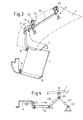
- FIG 3 shows a perspective view of the hood assembly with a double-rod-drive of the lifting devices 10 and 11.
- An additional push rod 24 is arranged between the lifting devices 10 and 11, driven by the first push-rod 13.
- the lifting mechanism of the rearward lifting device 11 is the same as of the forward lifting device 10.
- the sliding bolt 22 is replaced by a hinge bolt 25 to create a hinge for the hood 1, what is required for opening the hood 1 for service purposes.
- Figure 4 illustrates a sketch showing on principle another two-bar-link lifting device, in which the bars are linked together at a central pivot 26, the first bar 27 is supported with its outer end at a fixed body pivot 20.
- the push rod 13 acts at the end of the second bar 28, while the central pivot 26 lifts the hood 1.
Landscapes
- Engineering & Computer Science (AREA)
- Mechanical Engineering (AREA)
- Superstructure Of Vehicle (AREA)
Abstract
Description
- The present invention relates to a vehicle hood assembly for pedestrian protection in accordance with the preamble of
claim 1. - EP 1078826 discloses a pedestrian safety module device with a deployable hood. It consists of a tilting cross beam beneath the leading edge of the hood, and a hinge assembly at the trailing edge of the hood, whereby the hood is latched to the cross beam. In case of a pedestrian impact at the leading edge the cross beam is mechanically released to rotate, so that the hood is lowered at the leading edge. Simultaneously the rotational impulse of the hood is used to lift the trailing edge of the hood. A two bar link at the rear hinge assembly is released by the hood impulse and enables lifting of the trailing edge of the hood, and locks the hood in a deployed position.
- Although the hood is raised at the trailing edge, the forward area of the hood will not raise. To achieve more space between the hood and the engine parts, it is preferred to raise the hood also at the leading edge.
- Accordingly, it is a primary object of the present invention to provide a vehicle hood assembly, by which the hood can be lifted by using the impact energy of a pedestrian colliding with the vehicle.
- This object is achieved, according to the invention, in that one or more load transmission means are arranged between the cross car beam and at least one separate lifting device for the hood. A movement of the released cross member relative to the body is used to drive one or more separate lifting devices for the hood, whereby the transmission means transfer both movement and a load from the cross member to the lifting devices.
- When a pedestrian collides with the trailing edge of the hood, the hood is subjected to an impact load, which is transferred to the cross bar beam, e.g. by latch means and/or by bump stops. The cross car beam is attached to the vehicle body with releasable fixings, so that in case of an overload due to the impact load of a pedestrian the fixings release the cross car beam. Then both hood and cross car beam moves together mainly in the direction of the impact load. This movement is used to drive at least one lifting device for lifting the hood by arranging the load transmission means between cross car beam and lifting devices. Preferably several lifting devices are arranged at the trailing edge of the hood and near the fixing of the cross car beam. By this arrangement of the lifting devices and by driving the lifting devices with the movement of the cross car beam, the lifting of the hood could be achieved with only the impact load of the pedestrian.
- The hood assembly according to the invention works completely mechanical without the need of an additional control device, therefore no sophisticated and noisy electronic safety controls are required. Additionally the drive of the lifting device works without stored energy like airbags, pyrotechnic hinges, spring devices or other lifting devices known from prior art. This is a big advantage in so far as after years in service the stored energy may be reduced, e. g. because a spring is corroded, or the stored energy could not be activated, e.g. because of defective contacts in a pyrotechnic device.
- Although it is a big advantage of the hood assembly, that it is working completely mechanically, it could be useful to combine this system with other safety devices for pedestrian protection. Therefore also other safety devices for pedestrian protection like electronic safety sensors and controls, actuators etc. could be used in conjunction with the present invention.
- The object of the invention is also achieved, according to another embodiment of the invention, in that a movement of the released cross member relative to the body is used to drive at least one release mechanism of one or more separate lifting devices for the hood. Here the cross member acts in the same way as described in the previous embodiment. The only difference is, that now the movement of the cross member is used to drive any release mechanism of a lifting device. This could be used in conjunction with the previous embodiment, when the cross member first drives a release mechanism of the lifting device and then drives the lift device itself for lifting the hood. It could be also used to drive just a release mechanism of a lifting device, and than the released lifting device lifts the hood by with the support of stored energy as known from prior art.
- In a preferred embodiment the released cross member is guided in an elongated guide. The elongated guide can be e.g. a rail or a slotted hole, in which the cross car beam or a part of the cross car beam slides after the impact load has released the fixings. The guide provides a defined direction for the movement of the cross car beam, so that the drive for the lifting device can be attached accordingly to the cross car beam to get a maximum of displacement and acting force on the drive.
- In another preferred embodiment the released cross member is guided in a pivot guide. The pivot guide can be realised by supporting the cross car beam rotary in the vehicle body or, in conjunction with the previous embodiment, the cross car beam is supported rotary in the elongated guide, so that the cross car beam tilts around the pivot guide axis after the impact load has released the fixings. Also the pivot guide provides a defined tilting of the cross car beam, so that the drive for the lifting device can be attached accordingly to the cross car beam to get a maximum of displacement and acting force on the drive. It should be noted that both elongated guide and pivot guide could be used separate or in conjunction.
- Preferably the cross member is pivoted to a cooling pack. The task of the cooling pack is to support the cross beam, especially when the cross beam extends in forward direction at the centreline of the vehicle, while at the releasable fixings, located at the left and right ends of the cross bar, the cross bar extends more rearwards. As the cooling pack is mounted more or less rotary on a lower support beam, for example by fixing the cooling pack with elastic elements to the lower support beam, the whole cooling pack can tilt around the lower support beam. The cooling pack and the pivoted cross member builds a two bar link, so that in case of a pedestrian impact both can move and tilt together. By this the tilting of the cross beam during the movement of the cross beam can be defined exactly, which helps to get a more precise deformation for the drive of the lifting devices.
- The relative movement of the cross bar for the drive of a lifting device may be transferred with a rod. This could be a direct push rod, but is also possible to have several rods and bars linked together, so that the mechanical movement and force is transferred to lifting devices at the trailing at of the hood. Also cable or hydraulic means can be used to transfer the movement. This could be applied if there is not enough package space available to realise a direct rod connection.
- Advantageously the lifting device comprises a two bar link, whereby the bars are linked together at a central pivot, the first bar is supported with its outer end at a fixed body pivot, the drive of the lifting device acts at the central pivot, and the outer end of the second bar supports the hood. By this arrangement a high lift-displacement can be achieved with only few displacement of the drive respectively the cross car beam due to the double bar linkage. Further advantage is that the double bars are locked in the upper position so that the hood will stay in the upper position with no additional locking mechanism required.
- A further improvement is that the outer end of the second bar is supported on a rail, allowing transverse movement mainly in vertical directions. This guides the outer end of the second bar exactly in the direction where the lift is required. The outer end acts directly or indirectly, e.g. with additional bumper blocks, on the hood. So the hood lifts precisely in the direction of the rail.
- In another embodiment the lifting device comprises a two bar link, whereby the bars are linked together at a central pivot, the first bar is supported with its outer end at a fixed body pivot, the drive of the lifting device acts at the end of the second bar, and the central pivot supports the hood. Due to the double bar link the force of the drive is transformed, so that with relative low impact forces the hood can be lifted. Further advantage is that in the upper position the bars are locking the hood, so no additional locking mechanism is required.
- Further advantageous embodiments and designs are to be found in the drawings, in which shows:
- Fig. 1
- a perspective view of the hood assembly;
- Fig. 2a
- a sketch showing on principle the behaviour of the hood assembly during collision with a pedestrian with the un-lifted hood;
- Fig. 2b
- a sketch showing on principle the behaviour of the hood assembly during collision with a pedestrian with the lifted hood;
- Fig. 3
- a perspective view of the hood assembly with a double-rod-drive of the lifting devices; and
- Fig. 4
- a sketch showing on principle another two-bar-link lifting device.
- As illustrated in Figure 1, a vehicle hood assembly comprises a
hood 1 and an upperfront cross member 2 located below theleading edge 3 of thehood 1. As the hood assembly is fully symmetrically, only one side, starting at the centreline of the vehicle, is shown. Thecross car beam 2 is supported at its outer ends 4 at a releasable fixing 5, whereby the releasable fixing 5 is attached to the vehicle body, which is not shown here. Further thecross beam 2 comprises apivot 6, at which thecross beam 2 is connected rotary to thecooling pack 7. Thecooling pack 7 is supported on alower support beam 8, whereby alower pivot 9 ensures the rotary support betweenlower support beam 8 andcooling pack 7. Further the hood assembly comprises aforward lifting device 10, located near the releasable fixing 5, and arearward lifting device 11, located near the rearward edge of thehood 1. - The outer end 4 of the
cross beam 2 is supported in anelongated guide 12 of the releasable fixing 5, which allows in a released condition both transversal movement and tilting of thecross beam 2. To ensure that thecross car beam 2 can withstand in the unreleased condition normal service loads without moving and tilting in theelongated guide 12, at least on releasable connection is added between cross beam and releasable fixing 5, for example a shear pin like described in EP 1078826. Thecross beam 2 is connected with the liftingdevice 10 by a load transmission mean, thepush rod 13. - Figure 2a and 2b illustrates a sketch showing on principle the behaviour of the hood assembly during collision with a pedestrian, whereby Figure 2a illustrates the un-lifted hood and Figure 2b the lifted hood.
- When a pedestrian collides with the
leading edge 3 of thehood 1, the resulting impact load P is transferred from thehood 1 to thecross beam 2 by bump stops 14 and/or by thehood latch 15. Under the impact P theshear pin 16 fails and thecross beam 2, which is supported with itsbolt 17 in theelongated guide 12, is released. As shown in Figure 2b then thecross beam 2 slides along theelongated guide 12, which is preferably oriented in rearward vehicle direction. - Although the
cross beam 2 is supported also by thecooling pack 7, the cooling pack does not stop thecross car beam 2 from sliding backwards. As the cooling pack is supported double pivoted withpivot 6 to thecross beam 2 and with thelower pivot 9 to thelower support beam 8, the cooling pack acts as a double rotary supported bar, allowing the backwards moving of thecross beam 2 while only tilting it a little bit according to the geometrically arrangement of theelongated guide 12 and thepivots - The backwards sliding of the
cross beam 2 is transferred with thepush rod 13 from thecross beam 2 to thelifting device 9. The lifting mechanism comprises a two bar link, whereby the bars are linked together at acentral pivot 18. Thefirst bar 19 is supported with its outer end at afixed body pivot 20. Thepush road 13 as the drive of the lifting device acts at thecentral pivot 18, and the outer end of thesecond bar 21 is pivoted to a slidingbolt 22, which is guided in arail 23, oriented mainly in vertical direction. The slidingbolt 22 acts directly on thehood 1, lifting thehood 1 as shown in Figure 2b. - To ensure lifting of the
hood 1, also therearward lifting device 10 must be released in so far, that the rearward edge of thehood 1 can be raised as much as required. This can be realized according to a mechanism disclosed in EP 1078826 or any other mechanism known from prior art. - Figure 3 shows a perspective view of the hood assembly with a double-rod-drive of the
lifting devices additional push rod 24 is arranged between the liftingdevices rod 13. The lifting mechanism of therearward lifting device 11 is the same as of theforward lifting device 10. Just the slidingbolt 22 is replaced by ahinge bolt 25 to create a hinge for thehood 1, what is required for opening thehood 1 for service purposes. - Figure 4 illustrates a sketch showing on principle another two-bar-link lifting device, in which the bars are linked together at a
central pivot 26, thefirst bar 27 is supported with its outer end at afixed body pivot 20. Thepush rod 13 acts at the end of thesecond bar 28, while thecentral pivot 26 lifts thehood 1.
Claims (12)
- A vehicle hood assembly for pedestrian protection, including a hood (1) and an upper front cross member (2) located below the leading edge (3) of the hood (1), the cross member (2) is attached to the vehicle body with releasable fixings (5), whereby the fixings (5) release the cross beam (2) under an overload due to the impact load resulting from the collision of a pedestrian with the leading edge (3) of the hood (1),
characterised in that
one or more load transmission means are arranged between the cross car beam (2) and at least one separate lifting device (10, 11) for the hood. - A vehicle hood assembly according to claim 1,
characterised in that
a load transmission mean is connected with a drive mechanism of a lifting device. - A vehicle hood assembly according to claim 1 or 2,
characterised in that
a load transmission mean is connected with a release mechanism of a lifting device. - A vehicle hood assembly according to any of the preceding claims,
characterised in that
the released cross member (2) is guided in an elongated guide (12). - A vehicle hood assembly according to any of the preceding claims,
characterised in that
the released cross member (2) is guided in a pivot guide. - A vehicle hood assembly according to any of the preceding claims,
characterised in that
the cross member (2) is pivoted to a cooling pack (7). - A vehicle hood assembly according to claim 1, 2 or 3,
characterised in that
the load transmission mean is a rod (13, 24). - A vehicle hood assembly according to claim 1, 2 or 3,
characterised in that
the load transmission mean is a cable. - A vehicle hood assembly according to claim 1, 2 or 3,
characterised in that
the load transmission mean is a hydraulic device. - A vehicle hood assembly according to claim 1 or 2,
characterised in that
a lifting device (10, 11) comprises a two bar link, whereby the bars are linked together at a central pivot (18), the first bar (19) is supported with its outer end at a fixed body pivot (20), the drive of the lifting device acts at the central pivot (18), and the outer end of the second bar (21) supports the hood (1). - A vehicle hood assembly according to claim 10,
characterised in that
the outer end of the second bar (21) is guided on a rail (23), allowing transverse movement mainly in vertical directions. - A vehicle hood assembly according to claim 1 or 2,
characterised in that
a lifting device comprises a two bar link, whereby the bars are linked together at a central pivot (26), the first bar (27) is supported with its outer end at a fixed body pivot (20), the drive of the lifting device acts at the end of the second bar (28), and the central pivot (26) supports the hood (1).
Priority Applications (2)
| Application Number | Priority Date | Filing Date | Title |
|---|---|---|---|
| DE2001616697 DE60116697T2 (en) | 2001-10-16 | 2001-10-16 | Front hood arrangement for pedestrian protection |
| EP20010124637 EP1302388B1 (en) | 2001-10-16 | 2001-10-16 | Vehicle hood assembly for pedestrian protection |
Applications Claiming Priority (1)
| Application Number | Priority Date | Filing Date | Title |
|---|---|---|---|
| EP20010124637 EP1302388B1 (en) | 2001-10-16 | 2001-10-16 | Vehicle hood assembly for pedestrian protection |
Publications (2)
| Publication Number | Publication Date |
|---|---|
| EP1302388A1 true EP1302388A1 (en) | 2003-04-16 |
| EP1302388B1 EP1302388B1 (en) | 2006-01-18 |
Family
ID=8178975
Family Applications (1)
| Application Number | Title | Priority Date | Filing Date |
|---|---|---|---|
| EP20010124637 Expired - Lifetime EP1302388B1 (en) | 2001-10-16 | 2001-10-16 | Vehicle hood assembly for pedestrian protection |
Country Status (2)
| Country | Link |
|---|---|
| EP (1) | EP1302388B1 (en) |
| DE (1) | DE60116697T2 (en) |
Cited By (9)
| Publication number | Priority date | Publication date | Assignee | Title |
|---|---|---|---|---|
| DE10337555A1 (en) * | 2003-08-14 | 2005-03-10 | Volkswagen Ag | Radiator of vehicle, comprising holding elements fitted with detonators in order to facilitate deformation in case of collision with pedestrian |
| FR2868027A1 (en) * | 2004-03-29 | 2005-09-30 | Coutier Moulage Gen Ind | Passive safety system for motor vehicle, has ringed outer tube with deformable bellow shape having parallel undulations, and retractable support device allowing deformation of stop device in case of impact with pedestrian |
| FR2873086A1 (en) | 2004-07-16 | 2006-01-20 | Univ Pasteur | MULTILAYER HOOD WITH EXTERNALLY FRANGIBLE SKIN WITH REDUCED AGGRESSIVITY IN THE EVENT OF COLLISION WITH A PIETON |
| EP1398199A3 (en) * | 2002-09-09 | 2006-06-21 | Fuji Jukogyo Kabushiki Kaisha | Heat exchanger mounting structure for vehicle |
| DE102004061073A1 (en) * | 2004-12-18 | 2006-06-29 | Rehau Ag + Co | Pedestrian safety device for motor vehicle has triggering-device which is so designed that when force is within threshold value, it blocks lifting of engine hood and when it is above threshold value, it enables lifting of engine hood |
| EP2045146A1 (en) * | 2007-10-03 | 2009-04-08 | Ford Global Technologies, LLC | Pedestrian Safety Bonnet Latch Structure for a Motor Vehicle |
| JP2012086695A (en) * | 2010-10-20 | 2012-05-10 | Toyota Motor Corp | Pop-up hood device for vehicle |
| JP2017178205A (en) * | 2016-03-31 | 2017-10-05 | 株式会社Subaru | Cyclist protection device of vehicle |
| FR3058967A1 (en) * | 2016-11-23 | 2018-05-25 | Peugeot Citroen Automobiles Sa | FRONT PART OF A VEHICLE COMPRISING AN ACTIVE-TYPE COVER COMPRISING REINFORCING MEANS |
Families Citing this family (4)
| Publication number | Priority date | Publication date | Assignee | Title |
|---|---|---|---|---|
| DE102006042485A1 (en) * | 2006-09-07 | 2008-03-27 | Audi Ag | motor vehicle |
| DE102006055489B4 (en) * | 2006-09-15 | 2016-07-21 | Volkswagen Ag | Safety device on a vehicle |
| US8768574B1 (en) | 2013-02-22 | 2014-07-01 | Ventra Group, Inc. | Pedestrian protection vehicle hood hinge assembly |
| DE102013213793A1 (en) * | 2013-07-15 | 2015-01-15 | Volkswagen Aktiengesellschaft | Pedestrian protection device for a vehicle |
Citations (3)
| Publication number | Priority date | Publication date | Assignee | Title |
|---|---|---|---|---|
| US5437348A (en) * | 1991-04-16 | 1995-08-01 | Jaguar Cars Limited | Vehicle bonnets |
| GB2344080A (en) * | 1998-11-27 | 2000-05-31 | Brian Michael Temple | Device for reducing the damage to a person or animal struck by the front end of a vehicle |
| EP1078826A1 (en) * | 1999-08-21 | 2001-02-28 | Ford Global Technologies, Inc., A subsidiary of Ford Motor Company | Pedestrian safety module device |
-
2001
- 2001-10-16 DE DE2001616697 patent/DE60116697T2/en not_active Expired - Lifetime
- 2001-10-16 EP EP20010124637 patent/EP1302388B1/en not_active Expired - Lifetime
Patent Citations (3)
| Publication number | Priority date | Publication date | Assignee | Title |
|---|---|---|---|---|
| US5437348A (en) * | 1991-04-16 | 1995-08-01 | Jaguar Cars Limited | Vehicle bonnets |
| GB2344080A (en) * | 1998-11-27 | 2000-05-31 | Brian Michael Temple | Device for reducing the damage to a person or animal struck by the front end of a vehicle |
| EP1078826A1 (en) * | 1999-08-21 | 2001-02-28 | Ford Global Technologies, Inc., A subsidiary of Ford Motor Company | Pedestrian safety module device |
Cited By (10)
| Publication number | Priority date | Publication date | Assignee | Title |
|---|---|---|---|---|
| EP1398199A3 (en) * | 2002-09-09 | 2006-06-21 | Fuji Jukogyo Kabushiki Kaisha | Heat exchanger mounting structure for vehicle |
| DE10337555A1 (en) * | 2003-08-14 | 2005-03-10 | Volkswagen Ag | Radiator of vehicle, comprising holding elements fitted with detonators in order to facilitate deformation in case of collision with pedestrian |
| FR2868027A1 (en) * | 2004-03-29 | 2005-09-30 | Coutier Moulage Gen Ind | Passive safety system for motor vehicle, has ringed outer tube with deformable bellow shape having parallel undulations, and retractable support device allowing deformation of stop device in case of impact with pedestrian |
| FR2873086A1 (en) | 2004-07-16 | 2006-01-20 | Univ Pasteur | MULTILAYER HOOD WITH EXTERNALLY FRANGIBLE SKIN WITH REDUCED AGGRESSIVITY IN THE EVENT OF COLLISION WITH A PIETON |
| DE102004061073A1 (en) * | 2004-12-18 | 2006-06-29 | Rehau Ag + Co | Pedestrian safety device for motor vehicle has triggering-device which is so designed that when force is within threshold value, it blocks lifting of engine hood and when it is above threshold value, it enables lifting of engine hood |
| EP2045146A1 (en) * | 2007-10-03 | 2009-04-08 | Ford Global Technologies, LLC | Pedestrian Safety Bonnet Latch Structure for a Motor Vehicle |
| US7597384B2 (en) | 2007-10-03 | 2009-10-06 | Ford Global Technologies, Llc | Engine compartment hood latch structure for a motor vehicle |
| JP2012086695A (en) * | 2010-10-20 | 2012-05-10 | Toyota Motor Corp | Pop-up hood device for vehicle |
| JP2017178205A (en) * | 2016-03-31 | 2017-10-05 | 株式会社Subaru | Cyclist protection device of vehicle |
| FR3058967A1 (en) * | 2016-11-23 | 2018-05-25 | Peugeot Citroen Automobiles Sa | FRONT PART OF A VEHICLE COMPRISING AN ACTIVE-TYPE COVER COMPRISING REINFORCING MEANS |
Also Published As
| Publication number | Publication date |
|---|---|
| EP1302388B1 (en) | 2006-01-18 |
| DE60116697T2 (en) | 2006-08-31 |
| DE60116697D1 (en) | 2006-04-06 |
Similar Documents
| Publication | Publication Date | Title |
|---|---|---|
| EP1302388B1 (en) | Vehicle hood assembly for pedestrian protection | |
| EP3521111B1 (en) | Hinge arrangement | |
| EP0641707B1 (en) | Vehicle bonnets | |
| US6237992B1 (en) | Pedestrian safety module device | |
| KR101096169B1 (en) | Pedestrian protection automotive hood hinge assembly | |
| JP4453285B2 (en) | Control device for collision protection device | |
| US7497508B2 (en) | Bonnet for a vehicle | |
| US7575273B2 (en) | Bonnet bumpstop for a vehicle | |
| CN1352606A (en) | Front hood system of engine | |
| CN1352604A (en) | engine front cover | |
| EP1436465B1 (en) | Vehicle mounted crash attenuator cross reference to related patent application | |
| CN1351558A (en) | Front opening hood system | |
| JP2004536985A (en) | Hinge with two arms for front bonnet of motor vehicle | |
| AU2002329948A1 (en) | Vehicle Mounted Crash Attenuator | |
| EP1536991B1 (en) | A motor vehicle and a hinge assembly therefor | |
| KR20080026190A (en) | Truck with tilting device for driver's seat | |
| US7380625B2 (en) | Vehicle engine compartment hood | |
| EP3184377B1 (en) | Hinge arrangement | |
| EP3323683B1 (en) | Hinge arrangement | |
| EP2380787B1 (en) | Hinge Mechanism | |
| EP3184376B1 (en) | Hinge arrangement | |
| EP3243710B1 (en) | Bonnet deployment arrangement | |
| ES2279855T3 (en) | PROTECTIVE DEVICE FOR PEDESTRIES IN CASE OF FRONT SHOCK WITH A MOTOR VEHICLE. | |
| EP3184375B1 (en) | Hinge arrangement | |
| US20090102237A1 (en) | Vehicle Body for a Motor Vehicle |
Legal Events
| Date | Code | Title | Description |
|---|---|---|---|
| PUAI | Public reference made under article 153(3) epc to a published international application that has entered the european phase |
Free format text: ORIGINAL CODE: 0009012 |
|
| AK | Designated contracting states |
Designated state(s): AT BE CH CY DE DK ES FI FR GB GR IE IT LI LU MC NL PT SE TR |
|
| AX | Request for extension of the european patent |
Extension state: AL LT LV MK RO SI |
|
| 17P | Request for examination filed |
Effective date: 20031016 |
|
| AKX | Designation fees paid |
Designated state(s): DE FR GB |
|
| 17Q | First examination report despatched |
Effective date: 20040102 |
|
| RAP1 | Party data changed (applicant data changed or rights of an application transferred) |
Owner name: FORD GLOBAL TECHNOLOGIES, LLC |
|
| GRAP | Despatch of communication of intention to grant a patent |
Free format text: ORIGINAL CODE: EPIDOSNIGR1 |
|
| GRAS | Grant fee paid |
Free format text: ORIGINAL CODE: EPIDOSNIGR3 |
|
| GRAA | (expected) grant |
Free format text: ORIGINAL CODE: 0009210 |
|
| AK | Designated contracting states |
Kind code of ref document: B1 Designated state(s): DE FR GB |
|
| REG | Reference to a national code |
Ref country code: GB Ref legal event code: FG4D |
|
| REF | Corresponds to: |
Ref document number: 60116697 Country of ref document: DE Date of ref document: 20060406 Kind code of ref document: P |
|
| RAP2 | Party data changed (patent owner data changed or rights of a patent transferred) |
Owner name: FORD GLOBAL TECHNOLOGIES, LLC. |
|
| ET | Fr: translation filed | ||
| PLBE | No opposition filed within time limit |
Free format text: ORIGINAL CODE: 0009261 |
|
| STAA | Information on the status of an ep patent application or granted ep patent |
Free format text: STATUS: NO OPPOSITION FILED WITHIN TIME LIMIT |
|
| 26N | No opposition filed |
Effective date: 20061019 |
|
| PGFP | Annual fee paid to national office [announced via postgrant information from national office to epo] |
Ref country code: GB Payment date: 20090914 Year of fee payment: 9 |
|
| PGFP | Annual fee paid to national office [announced via postgrant information from national office to epo] |
Ref country code: DE Payment date: 20091030 Year of fee payment: 9 |
|
| PGFP | Annual fee paid to national office [announced via postgrant information from national office to epo] |
Ref country code: FR Payment date: 20091020 Year of fee payment: 9 |
|
| GBPC | Gb: european patent ceased through non-payment of renewal fee |
Effective date: 20101016 |
|
| PG25 | Lapsed in a contracting state [announced via postgrant information from national office to epo] |
Ref country code: FR Free format text: LAPSE BECAUSE OF NON-PAYMENT OF DUE FEES Effective date: 20101102 |
|
| REG | Reference to a national code |
Ref country code: FR Ref legal event code: ST Effective date: 20110630 |
|
| PG25 | Lapsed in a contracting state [announced via postgrant information from national office to epo] |
Ref country code: GB Free format text: LAPSE BECAUSE OF NON-PAYMENT OF DUE FEES Effective date: 20101016 |
|
| REG | Reference to a national code |
Ref country code: DE Ref legal event code: R119 Ref document number: 60116697 Country of ref document: DE Effective date: 20110502 |
|
| PG25 | Lapsed in a contracting state [announced via postgrant information from national office to epo] |
Ref country code: DE Free format text: LAPSE BECAUSE OF NON-PAYMENT OF DUE FEES Effective date: 20110502 |