EP1301382B1 - Optical precipitation sensor - Google Patents
Optical precipitation sensor Download PDFInfo
- Publication number
- EP1301382B1 EP1301382B1 EP01984227A EP01984227A EP1301382B1 EP 1301382 B1 EP1301382 B1 EP 1301382B1 EP 01984227 A EP01984227 A EP 01984227A EP 01984227 A EP01984227 A EP 01984227A EP 1301382 B1 EP1301382 B1 EP 1301382B1
- Authority
- EP
- European Patent Office
- Prior art keywords
- precipitation sensor
- mirror surface
- optical
- receiver
- reflective region
- Prior art date
- Legal status (The legal status is an assumption and is not a legal conclusion. Google has not performed a legal analysis and makes no representation as to the accuracy of the status listed.)
- Expired - Lifetime
Links
Images

Classifications
-
- G—PHYSICS
- G01—MEASURING; TESTING
- G01N—INVESTIGATING OR ANALYSING MATERIALS BY DETERMINING THEIR CHEMICAL OR PHYSICAL PROPERTIES
- G01N21/00—Investigating or analysing materials by the use of optical means, i.e. using sub-millimetre waves, infrared, visible or ultraviolet light
- G01N21/17—Systems in which incident light is modified in accordance with the properties of the material investigated
- G01N21/55—Specular reflectivity
- G01N21/552—Attenuated total reflection
-
- B—PERFORMING OPERATIONS; TRANSPORTING
- B60—VEHICLES IN GENERAL
- B60S—SERVICING, CLEANING, REPAIRING, SUPPORTING, LIFTING, OR MANOEUVRING OF VEHICLES, NOT OTHERWISE PROVIDED FOR
- B60S1/00—Cleaning of vehicles
- B60S1/02—Cleaning windscreens, windows or optical devices
- B60S1/04—Wipers or the like, e.g. scrapers
- B60S1/06—Wipers or the like, e.g. scrapers characterised by the drive
- B60S1/08—Wipers or the like, e.g. scrapers characterised by the drive electrically driven
- B60S1/0818—Wipers or the like, e.g. scrapers characterised by the drive electrically driven including control systems responsive to external conditions, e.g. by detection of moisture, dirt or the like
- B60S1/0822—Wipers or the like, e.g. scrapers characterised by the drive electrically driven including control systems responsive to external conditions, e.g. by detection of moisture, dirt or the like characterized by the arrangement or type of detection means
- B60S1/0833—Optical rain sensor
- B60S1/0837—Optical rain sensor with a particular arrangement of the optical elements
-
- B—PERFORMING OPERATIONS; TRANSPORTING
- B60—VEHICLES IN GENERAL
- B60S—SERVICING, CLEANING, REPAIRING, SUPPORTING, LIFTING, OR MANOEUVRING OF VEHICLES, NOT OTHERWISE PROVIDED FOR
- B60S1/00—Cleaning of vehicles
- B60S1/02—Cleaning windscreens, windows or optical devices
- B60S1/04—Wipers or the like, e.g. scrapers
- B60S1/06—Wipers or the like, e.g. scrapers characterised by the drive
- B60S1/08—Wipers or the like, e.g. scrapers characterised by the drive electrically driven
- B60S1/0818—Wipers or the like, e.g. scrapers characterised by the drive electrically driven including control systems responsive to external conditions, e.g. by detection of moisture, dirt or the like
- B60S1/0822—Wipers or the like, e.g. scrapers characterised by the drive electrically driven including control systems responsive to external conditions, e.g. by detection of moisture, dirt or the like characterized by the arrangement or type of detection means
- B60S1/0874—Wipers or the like, e.g. scrapers characterised by the drive electrically driven including control systems responsive to external conditions, e.g. by detection of moisture, dirt or the like characterized by the arrangement or type of detection means characterized by the position of the sensor on the windshield
- B60S1/0888—Wipers or the like, e.g. scrapers characterised by the drive electrically driven including control systems responsive to external conditions, e.g. by detection of moisture, dirt or the like characterized by the arrangement or type of detection means characterized by the position of the sensor on the windshield characterized by the attachment of the elements in a unit
-
- B—PERFORMING OPERATIONS; TRANSPORTING
- B60—VEHICLES IN GENERAL
- B60S—SERVICING, CLEANING, REPAIRING, SUPPORTING, LIFTING, OR MANOEUVRING OF VEHICLES, NOT OTHERWISE PROVIDED FOR
- B60S1/00—Cleaning of vehicles
- B60S1/02—Cleaning windscreens, windows or optical devices
- B60S1/04—Wipers or the like, e.g. scrapers
- B60S1/06—Wipers or the like, e.g. scrapers characterised by the drive
- B60S1/08—Wipers or the like, e.g. scrapers characterised by the drive electrically driven
- B60S1/0818—Wipers or the like, e.g. scrapers characterised by the drive electrically driven including control systems responsive to external conditions, e.g. by detection of moisture, dirt or the like
- B60S1/0822—Wipers or the like, e.g. scrapers characterised by the drive electrically driven including control systems responsive to external conditions, e.g. by detection of moisture, dirt or the like characterized by the arrangement or type of detection means
- B60S1/0862—Wipers or the like, e.g. scrapers characterised by the drive electrically driven including control systems responsive to external conditions, e.g. by detection of moisture, dirt or the like characterized by the arrangement or type of detection means including additional sensors
- B60S1/087—Wipers or the like, e.g. scrapers characterised by the drive electrically driven including control systems responsive to external conditions, e.g. by detection of moisture, dirt or the like characterized by the arrangement or type of detection means including additional sensors including an ambient light sensor
-
- B—PERFORMING OPERATIONS; TRANSPORTING
- B60—VEHICLES IN GENERAL
- B60S—SERVICING, CLEANING, REPAIRING, SUPPORTING, LIFTING, OR MANOEUVRING OF VEHICLES, NOT OTHERWISE PROVIDED FOR
- B60S1/00—Cleaning of vehicles
- B60S1/02—Cleaning windscreens, windows or optical devices
- B60S1/04—Wipers or the like, e.g. scrapers
- B60S1/06—Wipers or the like, e.g. scrapers characterised by the drive
- B60S1/08—Wipers or the like, e.g. scrapers characterised by the drive electrically driven
- B60S1/0818—Wipers or the like, e.g. scrapers characterised by the drive electrically driven including control systems responsive to external conditions, e.g. by detection of moisture, dirt or the like
- B60S1/0822—Wipers or the like, e.g. scrapers characterised by the drive electrically driven including control systems responsive to external conditions, e.g. by detection of moisture, dirt or the like characterized by the arrangement or type of detection means
- B60S1/0874—Wipers or the like, e.g. scrapers characterised by the drive electrically driven including control systems responsive to external conditions, e.g. by detection of moisture, dirt or the like characterized by the arrangement or type of detection means characterized by the position of the sensor on the windshield
- B60S1/0881—Wipers or the like, e.g. scrapers characterised by the drive electrically driven including control systems responsive to external conditions, e.g. by detection of moisture, dirt or the like characterized by the arrangement or type of detection means characterized by the position of the sensor on the windshield characterized by the attachment means on the windshield
-
- G—PHYSICS
- G01—MEASURING; TESTING
- G01N—INVESTIGATING OR ANALYSING MATERIALS BY DETERMINING THEIR CHEMICAL OR PHYSICAL PROPERTIES
- G01N21/00—Investigating or analysing materials by the use of optical means, i.e. using sub-millimetre waves, infrared, visible or ultraviolet light
- G01N21/17—Systems in which incident light is modified in accordance with the properties of the material investigated
- G01N21/41—Refractivity; Phase-affecting properties, e.g. optical path length
- G01N21/43—Refractivity; Phase-affecting properties, e.g. optical path length by measuring critical angle
- G01N2021/435—Sensing drops on the contact surface
Definitions
- This invention relates generally to precipitation sensors associated with monitoring the accumulation of precipitation upon window glass. More particularly, this invention relates to optical precipitation sensors used in automotive applications. Specifically, this invention relates to the optics used in automotive optical precipitation sensors and a method for their use.
- Optical sensors operate on the principle that a light beam is diffused or deflected from its normal path by the presence of water on the outer surface of the window.
- the systems that use optical sensors have the distinct advantage that they are sensing the same or similar phenomenon, which gives rise to the need for wiper operation, that being the disruption of the light transmissibility of the window glass caused by water residing on the outer surface.
- a beam of light in the infrared or near infrared ranges, is emitted into the window glass, from inside of the automobile, and at an angle giving rise to total reflection at the outer surface.
- a photoelectric device such as a photodiode or a phototransistor, then receives the reflected light and produces a representative electrical signal.
- the light received at the photoelectric device has certain characteristics when the outer surface is dry. The characteristics are altered when water is present on the outer surface, at the point where the light beam comes into contact with the outer surface. Since water has a refractive index close to that of glass, its presence causes a substantial portion of the light, which would otherwise be reflected to the receiver, to dissipate. This change in characteristics results in commensurate change in the electrical signal produced by the photoelectric device.
- the signal is processed by electronic circuitry to control the operation of the wipers.
- LED Light Emitting Diodes
- the approach using lenses, of the '303 patent apparently includes opaque members proximate and lateral to the optical axes of the reception lenses to block a portion of the ambient light reaching the receivers.
- the '291 patent does not discuss nor depict any means for blocking ambient light from reaching the receiver.
- the U. S. Patent numbered 4,798,956 to Hochstein employed two methods toward overcoming the ambient light problem.
- the receiver was placed at the bottom of a black tube to limit the number of directions from which ambient light could successfully reach the receiver.
- the use of infrared emitters was central to the second method employed.
- the '956 patent stated that infrared was used to compensate for ambient light. It indicated that commercially available infrared emitters emitted peak energy at 940 nm, in contrast to solar radiant energy peaking at approximately 500 nm.
- a filter was then placed in the tube between the opening of the tube and the receiver which passed the infrared light but rejected light of wavelengths shorter than infrared, including the peak solar wavelength of 500 nm.
- Solar glass includes additives to filter infrared and near infrared light from passing through the glass. Such glass protects the interior of the automobile from heating and other deleterious effects of this wavelength of light. However, it also substantially inhibits the infrared light of the emitter from reaching the receiver. It has been found that at least some infrared optical precipitation sensors are unusable in conjunction with such glass. The problem of ambient light rejection, evident in prior art designs, is exacerbated when the use of infrared emitters is no longer a viable option.
- the present invention has as an object the provision of an optical precipitation sensor with improved ambient light rejection.
- the present invention has the further object of allowing improved operation of an optical precipitation sensor in the least favorable light conditions expected to be encountered by an automotive precipitation sensor.
- the present invention has the further object of allowing the effective use of an optical precipitation sensor in conjunction with solar or thermal automotive glass.
- the invention is a precipitation sensor as defined in claim 1, adapted to detect water upon an automotive glass and a method for its use.
- the precipitation sensor includes an optical emitter and a first mirror surface in optical communication with the optical emitter. The first mirror surface is adapted to reflect and collimate light emission from the optical emitter.
- the precipitation sensor also includes an optical receiver and a second mirror surface in optical communication with the optical receiver. The second mirror surface is adapted to focus collimated light upon the optical receiver.
- the precipitation sensor further includes an intermediate reflector in optical communication with the first mirror surface and with the second mirror surface.
- optical precipitation sensor 10 of the instant invention is shown in relation to automobile 24, including an opening defined by, hood 12, side posts 14, roof 16, within which is located windshield 18.
- Windshield wipers 20 are shown in their rest position with the arcs of their sweep of operation shown by arcs 22.
- Optical precipitation sensor 10 is depicted in a preferred location within the reach of wipers 20 in operation. While mounting of optical precipitation sensor 10 is depicted upon windshield 18, mounting upon any window glass where sensing of precipitation is desired is contemplated, including rear or side windows, sunroofs, or headlamps.
- optical precipitation sensor 10 includes housing 28, which contains circuit board 30 and glass molding 38.
- Circuit board 30 serves as the mounting substrate for all of the electronic circuitry including electronic components 32, emitters 34 and receiver 36. These electronic components 32 process the signals related to emitters 34 and receiver 36 and provide an electrical interface to automobile 24 in a conventional manner known to those of ordinary skill in the art and will not be described herein.
- molding glass 38 is a single piece of glass and includes all optics of optical precipitation sensor 10, other than emitters 34 and receiver 36, and includes emitter optical notches 40, receiver optical notch 42, intermediate reflector 44, first mirror surfaces 52, and second mirror surface 54.
- Locator posts 66 also form part of glass molding 38, seen in Figure 3, and mate with holes (not depicted) on circuit board 30 to ensure consistent alignment of emitters 34 with emitter optical notches 40 and of receiver 36 with receiver optical notch 42.
- molding glass 38 preferably includes coloring agents to filter out ambient light 64 at wave lengths other than emitted by emitter 34, which further excludes ambient light 64 from accessing receiver 36.
- the glass composition used in application to clear and tinted windshields 18 is more preferably formulated to transmit the same wavelength of light as is emitted by emitters 34. Such filtering properties of the glass are achieved by adding the following colorants into the glass:
- each of said components, emitter optical notches 40, receiver optical notch 42, intermediate reflector 44, first mirror surfaces 52, second mirror surface 54, and locator posts 66 could be constructed of multiple elements fastened together mechanically or by adhesion.
- Housing 28 snap fits over circuit board 30 and molding glass 38 to secure the assembly and to maintain the mating relationship of locator posts 66 with the holes on circuit board 30.
- Optical precipitation sensor 10 is affixed to windshield 18 at mounting face 68 of molding glass 38 via transparent plastic adhesive tape 56.
- Mounting face 68 has a slightly convex shape to largely conform to the curvature of windshield 18. In this preferred embodiment it is assumed that windshield 18 has a deflection with a radius of approximately 3280 mm and a thickness of 4.7 ⁇ 0.2 mm.
- Emitter optical notches 40 are spherical depressions into molding glass 38 and located over emitters 34 such that emitted light 58 will primarily approach normal to the surface of emitted optical notches 40 for substantially all directions emitted light 58 departs from emitters 34. In this manner and under ideal conditions, emitted light 58 is not refracted upon passing through the boundary of emitter optical notches 40 and proceeds on a straight path to first mirror surface 52.
- First mirror surfaces 52 are parabolic surfaces upon molding glass 38 each with a focal point of 4.7 mm, an axis "a" of 60°, and metalized with a metallic film of aluminum. It is contemplated that other metals can be substituted for aluminum such as gold. Further, the coating does not need to be applied by metalization techniques or even be metal. It is contemplated that reflective plastic or other coatings, which are opaque can be used. The portion of the metallic film closest to mounting base 68 is the leading edge. As can be seen in Figure 4, this preferred embodiment employees three emitter optical notches 40 and three first mirror surfaces 52 over three emitters 34. This is done to increase the amount of emitted light 58 that can reach receiver 36.
- first mirror surface 52 results in emitted light 58 being reflected and collimated.
- Emitted light 58 proceeds on to first reflective region 46 of intermediate reflector 44.
- First reflective region 46 deviates from a straight line drawn between emitter optical notch 40 and receiver optical notch 42 by angle "c". Angle "c" is set at 7.5°.
- Intermediate reflector 44 can be metalized or not, depending on application. Not metalizing intermediate reflector 44 provides the benefit of additional ambient light 64 rejection by allowing ambient light 64 that approaches intermediate reflector 44 at less than total reflection angles pass through intermediate reflector 44.
- First reflective region 46 and second reflective region 48 each have mean reflective points defined as the average distance of the reflective area of each from mounting face 68.
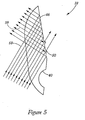
- This embodiment includes field regulators 50, which take the form of cones protruding from the surface of first reflective region 46 with an apex angle of 90°.
- Field regulators 50 have the effect of normalizing or otherwise controlling the intensity of emitted light 58 across the width of emitted light 58. As illustrated in Figure 5, a substantial portion of emitted light 58 that falls upon a field regulator 50 is not reflected leaving only a small portion, suppressed light 59, to continue on its working optical path toward receiver 36, with the remainder of emitted light 58 passing through field regulator 50.
- Field regulators 50 are placed at the points where it is desired to limit the intensity of emitted light 58.
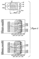
- Figure 6 is a plot of the field density of emitted light 58 in relation to location of emitters 34 and without the presence of water droplet 60.
- the left plot demonstrates the field density when no field regulators 50 are used.
- the right plot demonstrates the effects of field regulators 50 placed at locations on first reflective region 46 corresponding to the greatest field densities demonstrated in the left plot.
- the effect of field regulators 50 is to normalize the field densities across emitters 34. This technique provides the opportunity to normalize the effects of the presence of water droplet 60 upon windshield outer surface 26, within the later bounds of where emitted light 58 meets windshield outer surface 26, or the sensed area.
- This preferred embodiment depicted incorporates field regulators 50 upon first reflective region 46.
- field regulators 50 upon second reflective region 48, or upon a combination of first reflective region 46 and second reflective region 48.
- satisfactory performance can be achieved with an optical precipitation sensor 10 of the instant invention without the use of field regulators 50.
- Transparent plastic adhesive tape 56 is chosen to have a refractive index very close to that of the glass of windshield 18 to avoid losses caused by reflective and refractive effects. Further, for this embodiment, transparent plastic adhesive tape 56 has a thickness of 1.5 ⁇ 0.2 mm. Emitted light 58 proceeds to the boundary of air and windshield outer surface 26 and at angle that gives rise to total reflection.
- Second mirror surface 54 is a parabolic surface upon molding glass 38 with a focal point of 6 mm, an axis "b" of 45°, and metalized with aluminum. Second mirror surface 54 focuses emitted light 58 through receiver optical notch 42 and on to receiver 36.
- Receiver optical notch 42 is a spherical depression into molding glass 38 and located over receiver 36 such that emitted light 58 will primarily approach normal to the surface of receiver optical notch 42 for substantially all directions emitted light 58 passes from second mirror surface 54 to receiver 36. In this manner and under ideal conditions, emitted light 58 is not refracted upon passing through the boundary of receiver optical notch 42 and proceeds on a straight path to receiver 36.
- an issue that arises in connection with the use of optical sensors, for precipitation detection, is desensitization of receiver 36, by ambient light 64.
- Bright ambient light 64 such as sunlight impinging upon receiver 36, causes the photoelectric device to become relatively insensitive to emitted light 58. If enough ambient light impinges upon receiver 36, the signal produced by receiver 36 is not adequately different in response to the presence of water droplet 60 to be useable by electronic components 32 to reliably control wipers 20.
- this preferred embodiment uses a combination of choice of wavelength for emitted light 58 and filtering within glass molding 36 to reject a portion of ambient light 64.
- this alone is inadequate to insure proper operation of optical precipitation sensor 10. More protection from ambient light 64 is needed.
- the combination of the opaque nature of second mirror surface 54 caused by the aluminum metalization and its location facilitated by the presence of intermediate reflector 44 effectively rejects a substantial portion of ambient light 64 and thus shields receiver 36.
- the aluminum metalization can be continued to a leading edge at a point where emitted light 58 re-enters molding glass 38 after reflecting off of windshield outer surface 26.
- Intermediate reflector 44 allows such placement.
- second mirror surface 54 being intermediate to most sources of ambient light 64 except those sources which produce paths, through the sensed area, that are parallel to emitted light 58 within windshield 18. Further, that ambient light 64 with approach angles greater to windshield 18 than that which produce the above mentioned parallel paths do not have direct paths, via the combination of intermediate reflector 44 and second mirror surface 54, to receiver 36.
- optical precipitation sensor 10 in applications involving so-called solar or thermal automotive glass.
- Such glass contains additives that absorb light in the infrared or near infrared range of wavelengths.
- optical precipitation sensor 10 of the previously described embodiment or any optical precipitation sensor that uses emitters that emit light in the infrared or near infrared range
- this absorption reduces the field density reaching receiver 36 to an unusable level.
- the LED of emitter 34 is selected that emits light at wavelengths in the white light range that is not significantly absorbed by solar or thermal glass. In other prior art designs this would not be possible because the receiver would be overly exposed to ambient light.
- Emitter 34 of this preferred embodiment is an InGaAIP LED manufactured by OSRAM and designated "LA E675 Power TOPLED". It has the relative spectral emission described in table 5. Other LED's that have comparable characteristics may also be used. Table 5 Wavelength (nm) 590 600 610 620 630 640 650 660 I 0.04 0.11 0.33 1.0 0.42 0.06 0.01 0.00
- Receiver 36 of this preferred embodiment is also the Silicon NPN Phototransistor manufactured by VISHAY TELEFUNKEN and designated "TEMT4700", of the previous embodiment.
- Table 6 describes the relative spectral emissions pertinent to the LED used for emitter 34, of this embodiment.
- Table 6 Wavelength (nm) 600 620 640 660 680 700 720 740 I 0.43 0.47 0.56 0.60 0.62 0.65 0.69 0.78
- this embodiment tracks the embodiment previously discussed in detail.
Landscapes
- Engineering & Computer Science (AREA)
- Automation & Control Theory (AREA)
- Mechanical Engineering (AREA)
- Physics & Mathematics (AREA)
- Health & Medical Sciences (AREA)
- Life Sciences & Earth Sciences (AREA)
- Chemical & Material Sciences (AREA)
- Analytical Chemistry (AREA)
- Biochemistry (AREA)
- General Health & Medical Sciences (AREA)
- General Physics & Mathematics (AREA)
- Immunology (AREA)
- Pathology (AREA)
- Investigating Or Analysing Materials By Optical Means (AREA)
- Glass Compositions (AREA)
- Investigating Or Analysing Materials By The Use Of Chemical Reactions (AREA)
Abstract
Description
- This invention relates generally to precipitation sensors associated with monitoring the accumulation of precipitation upon window glass. More particularly, this invention relates to optical precipitation sensors used in automotive applications. Specifically, this invention relates to the optics used in automotive optical precipitation sensors and a method for their use.
- It is desirable to free the driver, operating an automobile, from the distractions of manually performing certain functions associated with the operation of the automobile. Comfort and safety can be both served by automating these functions. Operation of the wipers for the windshield or other window glass of an automobile, is a function that has been automated.
- Automating the operation of these wipers requires sensing the presence of water, or precipitation, upon the outer surfaces of the window glass. When water is sensed, a signal is generated, electronic circuitry processes the signal, and the wipers are automatically deployed to clear the water from the window glass surface. Several approaches have been taken toward this sensing of water on window glass. These have included sensing a change in conductivity or capacitance, at a sampling point upon the outer surface, when moisture is present. These have included acoustic effects produced by raindrops hitting the surface of the automobile (e.g. rain landing upon the window glass or some other portion of the vehicle). These approaches have also included various optical techniques.
- Optical sensors operate on the principle that a light beam is diffused or deflected from its normal path by the presence of water on the outer surface of the window. The systems that use optical sensors have the distinct advantage that they are sensing the same or similar phenomenon, which gives rise to the need for wiper operation, that being the disruption of the light transmissibility of the window glass caused by water residing on the outer surface.
- Generally, a beam of light, in the infrared or near infrared ranges, is emitted into the window glass, from inside of the automobile, and at an angle giving rise to total reflection at the outer surface. A photoelectric device, such as a photodiode or a phototransistor, then receives the reflected light and produces a representative electrical signal. The light received at the photoelectric device has certain characteristics when the outer surface is dry. The characteristics are altered when water is present on the outer surface, at the point where the light beam comes into contact with the outer surface. Since water has a refractive index close to that of glass, its presence causes a substantial portion of the light, which would otherwise be reflected to the receiver, to dissipate. This change in characteristics results in commensurate change in the electrical signal produced by the photoelectric device. The signal is processed by electronic circuitry to control the operation of the wipers.
- A recent approach disclosed in U. S. Patent numbered 5,661,303 to Teder, for producing an optical precipitation sensor, includes the use of emission lenses to collimate infrared light emitted from multiple Light Emitting Diodes (LED) and to direct the light upon the outer surface of the window glass at angles giving rise to total reflection. Receiption lenses are then used to direct and focus the reflected emitted light upon receivers.
- Another recent approach is disclosed in Czech Republic Patent numbered CZ 285,291 B6, to Lan et al., uses a rotational parabolic mirror to collimate and direct near infrared light from multiple LED's upon the outer surface at an angle giving rise to total reflection. The reflected emitted light is then directed and focused upon a receiver by another rotational parabolic mirror.
- An issue that arises in connection with the use of optical sensors, for precipitation detection, is desensitization of the photoelectric device of the receiver, by ambient light. Bright ambient light, such as sunlight, impinging upon the photoelectric device of the receiver, causes the device to become relatively insensitive to the emitted light transmitted to the receiver. If enough ambient light is impinging upon the receiver, the signal produced by the receiver may not be adequately different, in response to the presence of water on the outer surface, to be useable by the electronics to reliably control the wipers.
- The approach using lenses, of the '303 patent, apparently includes opaque members proximate and lateral to the optical axes of the reception lenses to block a portion of the ambient light reaching the receivers. The '291 patent does not discuss nor depict any means for blocking ambient light from reaching the receiver.
- The U. S. Patent numbered 4,798,956 to Hochstein employed two methods toward overcoming the ambient light problem. For the first method, the receiver was placed at the bottom of a black tube to limit the number of directions from which ambient light could successfully reach the receiver. The use of infrared emitters was central to the second method employed. The '956 patent stated that infrared was used to compensate for ambient light. It indicated that commercially available infrared emitters emitted peak energy at 940 nm, in contrast to solar radiant energy peaking at approximately 500 nm. A filter was then placed in the tube between the opening of the tube and the receiver which passed the infrared light but rejected light of wavelengths shorter than infrared, including the peak solar wavelength of 500 nm.
- Apparently, none of the approaches disclosed adequately protect the receiver from ambient light to ensure proper sensing of water on an outer surface of a window glass, in all light conditions expected to be encountered by a precipitation sensor.
- Additionally, the advent of solar or thermal glass, for automotive applications, creates new challenges for the optical precipitation sensor designer. Solar glass includes additives to filter infrared and near infrared light from passing through the glass. Such glass protects the interior of the automobile from heating and other deleterious effects of this wavelength of light. However, it also substantially inhibits the infrared light of the emitter from reaching the receiver. It has been found that at least some infrared optical precipitation sensors are unusable in conjunction with such glass. The problem of ambient light rejection, evident in prior art designs, is exacerbated when the use of infrared emitters is no longer a viable option.
- Accordingly, there remains the need for an optical precipitation sensor exhibiting improved ambient light rejection particularly when used in conjunction with solar or thermal glass.
- The present invention has as an object the provision of an optical precipitation sensor with improved ambient light rejection.
- The present invention has the further object of allowing improved operation of an optical precipitation sensor in the least favorable light conditions expected to be encountered by an automotive precipitation sensor.
- The present invention has the further object of allowing the effective use of an optical precipitation sensor in conjunction with solar or thermal automotive glass.
- To achieve the foregoing and other objects in accordance with the purposes of the present invention, as embodied and broadly described herein, an optical precipitation sensor and method is disclosed herein. The invention is a precipitation sensor as defined in claim 1, adapted to detect water upon an automotive glass and a method for its use. The precipitation sensor includes an optical emitter and a first mirror surface in optical communication with the optical emitter. The first mirror surface is adapted to reflect and collimate light emission from the optical emitter. The precipitation sensor also includes an optical receiver and a second mirror surface in optical communication with the optical receiver. The second mirror surface is adapted to focus collimated light upon the optical receiver. The precipitation sensor further includes an intermediate reflector in optical communication with the first mirror surface and with the second mirror surface. The features of the present invention that are known from DE-A-198 21 335 have been placed in the preamble of claim 1.
- The accompanying drawings, which are incorporated in and form part of the specification in which like numerals designate like parts, illustrate preferred embodiments of the present invention and together with the description, serve to explain the principles of the invention. In the drawings:
- Figure 1 is a fragmentary perspective depicting an optical precipitation sensor mounted upon a windshield of an automobile;
- Figure 2 is a transverse section of the optical precipitation sensor and windshield, taken along line 2-2 of Figure 1;
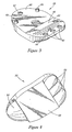
- Figure 3 is a perspective of the glass molding.
- Figure 4 is a perspective of the glass molding.
- Figure 5 is a fragmentary section showing the field regulator in greater detail.
- Figure 6 is a graph showing the effect of the field regulator.
- Referring to Figure 1,
optical precipitation sensor 10 of the instant invention is shown in relation toautomobile 24, including an opening defined by,hood 12, side posts 14,roof 16, within which is locatedwindshield 18.Windshield wipers 20 are shown in their rest position with the arcs of their sweep of operation shown byarcs 22.Optical precipitation sensor 10 is depicted in a preferred location within the reach ofwipers 20 in operation. While mounting ofoptical precipitation sensor 10 is depicted uponwindshield 18, mounting upon any window glass where sensing of precipitation is desired is contemplated, including rear or side windows, sunroofs, or headlamps. - Referring to Figures 2, 3, and 4
optical precipitation sensor 10 includeshousing 28, which containscircuit board 30 andglass molding 38.Circuit board 30 serves as the mounting substrate for all of the electronic circuitry includingelectronic components 32,emitters 34 andreceiver 36. Theseelectronic components 32 process the signals related toemitters 34 andreceiver 36 and provide an electrical interface toautomobile 24 in a conventional manner known to those of ordinary skill in the art and will not be described herein. - In this preferred embodiment,
molding glass 38 is a single piece of glass and includes all optics ofoptical precipitation sensor 10, other thanemitters 34 andreceiver 36, and includes emitteroptical notches 40, receiveroptical notch 42,intermediate reflector 44, first mirror surfaces 52, andsecond mirror surface 54. Locator posts 66 also form part ofglass molding 38, seen in Figure 3, and mate with holes (not depicted) oncircuit board 30 to ensure consistent alignment ofemitters 34 with emitteroptical notches 40 and ofreceiver 36 with receiveroptical notch 42. - As will be discussed below, the configuration of the instant invention, using
second mirror surface 54 to shieldreceiver 36, very substantially reduces access of ambient light toreceiver 36. However,molding glass 38 preferably includes coloring agents to filter out ambient light 64 at wave lengths other than emitted byemitter 34, which further excludes ambient light 64 from accessingreceiver 36. The glass composition used in application to clear andtinted windshields 18 is more preferably formulated to transmit the same wavelength of light as is emitted byemitters 34. Such filtering properties of the glass are achieved by adding the following colorants into the glass: - CoO (in the range from 0.01wt.% to 1.0 wt.%)
- CeO2 (in the range from 0.0 wt.% to 6.0 wt.%)
- TiO2 (in the range from 0.0 wt.% to 11.0 wt.%)
- NiO (in the range from 0.0 wt.% to 0.6 wt.%)
- It is also contemplated that each of said components, emitter
optical notches 40, receiveroptical notch 42,intermediate reflector 44, first mirror surfaces 52,second mirror surface 54, and locator posts 66, could be constructed of multiple elements fastened together mechanically or by adhesion.Housing 28 snap fits overcircuit board 30 andmolding glass 38 to secure the assembly and to maintain the mating relationship of locator posts 66 with the holes oncircuit board 30.Optical precipitation sensor 10 is affixed towindshield 18 at mountingface 68 ofmolding glass 38 via transparent plasticadhesive tape 56. Mountingface 68 has a slightly convex shape to largely conform to the curvature ofwindshield 18. In this preferred embodiment it is assumed thatwindshield 18 has a deflection with a radius of approximately 3280 mm and a thickness of 4.7±0.2 mm. -
Emitters 34 of this preferred embodiment are GaAs LED's manufactured by OSRAM and designated "SFM 420 TOPLED". It has the relative spectral emission described in table 2. Its radiation characteristics are that of a cosine emitter and has an active chip area: A = L x W=0.3 mm x 0.3 mm = 0.09 mm2. LED's of comparable characteristics can also be used.Table 2 Wavelength (nm) 900 920 940 950 960 980 1000 1020 I 0.04 0.18 0.87 1.0 0.90 0.55 0.20 0.06 - Emitter
optical notches 40 are spherical depressions intomolding glass 38 and located overemitters 34 such that emitted light 58 will primarily approach normal to the surface of emittedoptical notches 40 for substantially all directions emitted light 58 departs fromemitters 34. In this manner and under ideal conditions, emittedlight 58 is not refracted upon passing through the boundary of emitteroptical notches 40 and proceeds on a straight path tofirst mirror surface 52. - First mirror surfaces 52 are parabolic surfaces upon
molding glass 38 each with a focal point of 4.7 mm, an axis "a" of 60°, and metalized with a metallic film of aluminum. It is contemplated that other metals can be substituted for aluminum such as gold. Further, the coating does not need to be applied by metalization techniques or even be metal. It is contemplated that reflective plastic or other coatings, which are opaque can be used. The portion of the metallic film closest to mountingbase 68 is the leading edge. As can be seen in Figure 4, this preferred embodiment employees three emitteroptical notches 40 and three first mirror surfaces 52 over threeemitters 34. This is done to increase the amount of emitted light 58 that can reachreceiver 36. This provides the benefit of improving the signal to noise ratio of emitted light 58 to any stray light that might reachreceiver 36 in spite of the shielding techniques that form part of the instant invention. Further, the number ofemitters 34, and associatedoptical notches 40 and first mirror surfaces 52 can be selected to produce field intensities that optimizes operation ofreceiver 36, which is dependent upon system geometry, photoelectric device properties, and the sensor production tolerances. The configuration offirst mirror surface 52 results in emitted light 58 being reflected and collimated. - Emitted light 58 proceeds on to first
reflective region 46 ofintermediate reflector 44. Firstreflective region 46 deviates from a straight line drawn between emitteroptical notch 40 and receiveroptical notch 42 by angle "c". Angle "c" is set at 7.5°.Intermediate reflector 44 can be metalized or not, depending on application. Not metalizingintermediate reflector 44 provides the benefit of additional ambient light 64 rejection by allowing ambient light 64 that approachesintermediate reflector 44 at less than total reflection angles pass throughintermediate reflector 44. Firstreflective region 46 and secondreflective region 48 each have mean reflective points defined as the average distance of the reflective area of each from mountingface 68. - This embodiment includes
field regulators 50, which take the form of cones protruding from the surface of firstreflective region 46 with an apex angle of 90°.Field regulators 50 have the effect of normalizing or otherwise controlling the intensity of emitted light 58 across the width of emittedlight 58. As illustrated in Figure 5, a substantial portion of emitted light 58 that falls upon afield regulator 50 is not reflected leaving only a small portion, suppressedlight 59, to continue on its working optical path towardreceiver 36, with the remainder of emitted light 58 passing throughfield regulator 50.Field regulators 50 are placed at the points where it is desired to limit the intensity of emittedlight 58. - Figure 6 is a plot of the field density of emitted light 58 in relation to location of
emitters 34 and without the presence ofwater droplet 60. The left plot demonstrates the field density when nofield regulators 50 are used. The right plot demonstrates the effects offield regulators 50 placed at locations on firstreflective region 46 corresponding to the greatest field densities demonstrated in the left plot. As can be seen, the effect offield regulators 50 is to normalize the field densities acrossemitters 34. This technique provides the opportunity to normalize the effects of the presence ofwater droplet 60 upon windshieldouter surface 26, within the later bounds of where emitted light 58 meets windshieldouter surface 26, or the sensed area. Thus, if water droplet 60 lands at various locations upon windshieldouter surface 26 and within the sensed area, the level of change of intensity of emitted light 58 caused by the variations of location is normalized. This allows more consistent variation of emitted light 58 intensity regardless of water drop location within the sensed area. - This preferred embodiment depicted incorporates
field regulators 50 upon firstreflective region 46. However, it is expected that comparable results can be obtained through the placement offield regulators 50 upon secondreflective region 48, or upon a combination of firstreflective region 46 and secondreflective region 48. Further, it has been determined that for certain applications, satisfactory performance can be achieved with anoptical precipitation sensor 10 of the instant invention without the use of field regulators 50. - After reflecting from first
reflective region 46, emitted light 58 proceeds through transparentplastic tape 56 and intowindshield 18. Transparent plasticadhesive tape 56 is chosen to have a refractive index very close to that of the glass ofwindshield 18 to avoid losses caused by reflective and refractive effects. Further, for this embodiment, transparent plasticadhesive tape 56 has a thickness of 1.5±0.2 mm. Emitted light 58 proceeds to the boundary of air and windshieldouter surface 26 and at angle that gives rise to total reflection. - The formula for the calculation of the total reflection is:


- where α = angle of the light beam going from glass to air
- β = angle of the beam after crossing the boundary between glass and air
- n 1 = refractive index of the glass (n=1.515)
- n2 = refractive index of air (n=1)
- 1 = glass
- 2 = air
- If windshield
outer surface 26 is dry, then emitted light 58 reflects completely according to the principle of total reflection described above. Emitted light 58 then passes through transparent plasticadhesive tape 56 to secondreflective region 48 ofintermediate reflector 44 and then reflects tosecond mirror surface 54.Second mirror surface 54 is a parabolic surface uponmolding glass 38 with a focal point of 6 mm, an axis "b" of 45°, and metalized with aluminum.Second mirror surface 54 focuses emitted light 58 through receiveroptical notch 42 and on toreceiver 36. Receiveroptical notch 42 is a spherical depression intomolding glass 38 and located overreceiver 36 such that emitted light 58 will primarily approach normal to the surface of receiveroptical notch 42 for substantially all directions emitted light 58 passes fromsecond mirror surface 54 toreceiver 36. In this manner and under ideal conditions, emittedlight 58 is not refracted upon passing through the boundary of receiveroptical notch 42 and proceeds on a straight path toreceiver 36. -
Receiver 36 of this preferred embodiment is a Silicon NPN Phototransistor manufactured by VISHAY TELEFUNKEN and designated "TEMT4700". It has the relative spectral emission described in table 3. Its relative directional sensitivity follows a cosine characteristic and has an active chip area A = L x W = 0.74 mm x 0.74 mm = 0.55 mm2.. Phototransistors of comparable characteristics can also be used.Table 3 Wavelength (nm) 900 920 940 950 960 980 1000 1020 I 0.94 0.87 0.77 0.71 0.68 0.54 0.43 0.34 pair comprising emitter 34 andreceiver 36 is described in table 4.Table 4 Wavelength (nm) 900 920 940 950 960 980 1000 1020 I 0.054 0.221 0.944 1.0 0.862 0.418 0.121 0.028 - Referring to Figures 3 and 4, it can be seen that only one
second mirror surface 54, receiveroptical notch 42, andreceiver 36 are used in this preferred embodiment. A plurality of these can be employed to increase the sensed area upon windshieldouter surface 26. It is believed that any benefit to be derived is outweighed by the additional size and complexity added tooptical precipitation sensor 10. - The process described above, where no
water droplet 60 is present, creates a predictable field intensity uponreceiver 36 and resulting signal fromreceiver 36, to the limits of the stability of the electronic devices, includingemitters 34 andreceiver 36. Whenwater droplet 60 is present, as depicted in Figure 2, the close relationship of the refractive index of glass and water, optically softens the boundary at windshieldouter surface 26 and disturbs the total reflection condition. This, in-turn, causes a substantial portion of emitted light 58 to pass through the boundary as dissipatedlight 62. This alters the field density atreceiver 36 and thus the signal produced byreceiver 36 in a manner processable by theelectronic components 32 to produce a signal to operatewipers 20. - As has been referenced above, an issue that arises in connection with the use of optical sensors, for precipitation detection, is desensitization of
receiver 36, byambient light 64. Brightambient light 64, such as sunlight impinging uponreceiver 36, causes the photoelectric device to become relatively insensitive to emittedlight 58. If enough ambient light impinges uponreceiver 36, the signal produced byreceiver 36 is not adequately different in response to the presence ofwater droplet 60 to be useable byelectronic components 32 to reliably controlwipers 20. - As has been described, this preferred embodiment uses a combination of choice of wavelength for emitted light 58 and filtering within
glass molding 36 to reject a portion ofambient light 64. However, this alone is inadequate to insure proper operation ofoptical precipitation sensor 10. More protection fromambient light 64 is needed. The combination of the opaque nature ofsecond mirror surface 54 caused by the aluminum metalization and its location facilitated by the presence ofintermediate reflector 44 effectively rejects a substantial portion ofambient light 64 and thus shieldsreceiver 36. - As can be seen in Figure 2, the aluminum metalization can be continued to a leading edge at a point where emitted light 58
re-enters molding glass 38 after reflecting off of windshieldouter surface 26.Intermediate reflector 44 allows such placement. This results insecond mirror surface 54 being intermediate to most sources of ambient light 64 except those sources which produce paths, through the sensed area, that are parallel to emitted light 58 withinwindshield 18. Further, that ambient light 64 with approach angles greater towindshield 18 than that which produce the above mentioned parallel paths do not have direct paths, via the combination ofintermediate reflector 44 andsecond mirror surface 54, toreceiver 36. - This optical geometry is so successful at rejecting
ambient light 64 that it has provided the opportunity to useoptical precipitation sensor 10 in applications involving so-called solar or thermal automotive glass. Such glass contains additives that absorb light in the infrared or near infrared range of wavelengths. Whenoptical precipitation sensor 10, of the previously described embodiment (or any optical precipitation sensor that uses emitters that emit light in the infrared or near infrared range), is applied towindshield 18 made of such glass, this absorption reduces the fielddensity reaching receiver 36 to an unusable level. - This leads to a preferred embodiment where
glass molding 38 has no colorants, to filter light, added thereto. Further, the LED ofemitter 34 is selected that emits light at wavelengths in the white light range that is not significantly absorbed by solar or thermal glass. In other prior art designs this would not be possible because the receiver would be overly exposed to ambient light. -
Emitter 34 of this preferred embodiment is an InGaAIP LED manufactured by OSRAM and designated "LA E675 Power TOPLED". It has the relative spectral emission described in table 5. Other LED's that have comparable characteristics may also be used.Table 5 Wavelength (nm) 590 600 610 620 630 640 650 660 I 0.04 0.11 0.33 1.0 0.42 0.06 0.01 0.00 -
Receiver 36 of this preferred embodiment is also the Silicon NPN Phototransistor manufactured by VISHAY TELEFUNKEN and designated "TEMT4700", of the previous embodiment. Table 6 describes the relative spectral emissions pertinent to the LED used foremitter 34, of this embodiment.Table 6 Wavelength (nm) 600 620 640 660 680 700 720 740 I 0.43 0.47 0.56 0.60 0.62 0.65 0.69 0.78 - In all other respects, this embodiment tracks the embodiment previously discussed in detail.
- The foregoing description and illustrative embodiments of the present invention have been shown on the drawings and described in detail in varying modifications and alternative embodiments. It should be understood, however, that the foregoing description of the invention is exemplary only, and that the scope of the invention is to be limited only to the claims as interpreted in view of the prior art. Moreover, the invention illustratively disclosed herein suitably may be practiced in the absence of any element which is not specifically disclosed herein.
| Oxide | SiO2 | CaO | K2O | Na2O | B2O3 | Al2O3 | Fe2O3 | CoO | CeO2 | TiO2 |
| Wt. % | 61.42 | 1.6 | 13.89 | 8.19 | 1.33 | 0.97 | 0.01 | 0.37 | 4.26 | 8.00 |
Claims (26)
- A precipitation sensor (10) to sense the presence of water upon an automotive glass, the sensor (10) having: an optical emitter (34), an optical receiver (36), a first mirror surface (52) for collimating light emitted from said optical emitter (34), a second mirror surface (54) for focusing said emitted light upon said optical receiver (36), and an electronic circuit in electrical communication with said optical emitter (34) and said optical receiver (36);
said precipitation sensor (10) being characterised by also including an intermediate reflector (44), wherein said intermediate reflector (44) comprises a first reflective region (46) proximate said emitter (34) and a second reflective region (48) proximate said receiver (36), and whereby the precipitation sensor (10) has a working optical path from said emitter (34) to said first mirror surface (52) to said first reflective region (46) to an outer surface of said automotive glass to said second reflective region (48) to said second mirror surface (54) to said receiver (36). - The precipitation sensor (10) of claim 1, further comprising:said first reflective region (46) being adapted to substantially pass light falling upon said first reflective region (46) at angles not giving rise to total reflection.
- The precipitation sensor (10) of claim 1 or 2, further comprising:said second reflective region (48) being adapted to substantially pass light falling upon said second reflective region (48) at angles not giving rise to total reflection.
- The precipitation sensor (10) of claim 1, 2 or 3 further comprising:said first reflective region (46) having a first mean reflective point being displaced from said automotive glass at a distance at least as great as a distance a first leading edge of said first mirror surface (52) is displaced from said automotive glass.
- The precipitation sensor (10) of claim 1, 2, 3 or 4 further comprising:said second reflective region (48) having a second mean reflective point being displaced from said automotive glass at a distance at least as great as a distance a second leading edge of said second mirror surface (54) is displaced from said automotive glass.
- The precipitation sensor (10) of any one of the preceding claims, further comprising:said working optical path being substantially within solid optical-elements.
- The precipitation sensor (10) of any one of the preceding claims, further comprising:said intermediate reflector (44) including a field regulator.
- The precipitation sensor (10) of claim 7 wherein:said field regulator comprises at least one cone.
- The precipitation sensor (10) of any one of the preceding claims, further comprising:said first reflective region (46) field including a field regulator.
- The precipitation sensor (10) of any one of the preceding claims, further comprising:said second reflective region (48) field including a field regulator.
- The precipitation sensor (10) of any one of the preceding claims wherein:said first mirror surface (52), said second mirror surface (54), and said intermediate reflector (44) comprise a single optical unit.
- The precipitation sensor (10) of any one of the preceding claims, wherein:said second mirror surface (54) is opaque and is placed intermediate to said optical receiver (36) and a source of ambient light opposite of said automotive glass from said second mirror surface (54).
- The precipitation sensor (10) of any one of the preceding claims, further comprising:said first mirror surface (52) being aspheric.
- The precipitation sensor (10) of claim 13 further comprising:said first aspheric mirror being hyperbolic.
- the precipitation sensor (10) of any one of the preceding claims, further comprising:said second mirror surface (54) being aspheric.
- The precipitation sensor (10) of claim 15 further comprising:said second aspheric mirror being hyperbolic.
- The precipitation sensor (10) of any one of the preceding claims, further comprising:said first mirror being coated with a reflective film.
- The precipitation sensor (10) of any one of the preceding claims, further comprising:said second mirror being coated with a reflective film.
- The precipitation sensor (10) of any one of the preceding claims, wherein:said emitter (34) is adapted to emit light in the visible light range.
- The precipitation sensor (10) of claim 19, further comprising:said second mirror surface (54) being opaque and being placed intermediate to said optical receiver (36) and a source of ambient light opposite of said automotive glass from said second mirror surface (54).
- The precipitation sensor (10) of any of the preceding claims further having a field regulator.
- The precipitation sensor (10) of claim 21, the field regulator comprising at least one cone.
- The precipitation sensor (10) of claim 21 or claim 22 further comprising a second field regulator.
- The precipitation sensor (10) of claim 23, the second field regulator comprising at least one cone.
- The precipitation sensor (10) of any one of the preceding claims, wherein said first reflective region (46) deviates from a straight line drawn between the emitter (34) and the receiver (36) by an angle of 7.5°.
- The precipitation sensor (10) of claim 25, wherein the second reflective region (48) is parallel to that straight line.
Applications Claiming Priority (3)
| Application Number | Priority Date | Filing Date | Title |
|---|---|---|---|
| US21917000P | 2000-07-19 | 2000-07-19 | |
| US219170P | 2000-07-19 | ||
| PCT/US2001/022874 WO2002006095A1 (en) | 2000-07-19 | 2001-07-19 | Optical precipitation sensor |
Publications (2)
| Publication Number | Publication Date |
|---|---|
| EP1301382A1 EP1301382A1 (en) | 2003-04-16 |
| EP1301382B1 true EP1301382B1 (en) | 2007-03-07 |
Family
ID=22818163
Family Applications (1)
| Application Number | Title | Priority Date | Filing Date |
|---|---|---|---|
| EP01984227A Expired - Lifetime EP1301382B1 (en) | 2000-07-19 | 2001-07-19 | Optical precipitation sensor |
Country Status (8)
| Country | Link |
|---|---|
| US (2) | US6855947B2 (en) |
| EP (1) | EP1301382B1 (en) |
| JP (1) | JP3843069B2 (en) |
| AT (1) | ATE356007T1 (en) |
| AU (1) | AU2002222923A1 (en) |
| CA (1) | CA2415332C (en) |
| DE (1) | DE60127130T2 (en) |
| WO (1) | WO2002006095A1 (en) |
Cited By (2)
| Publication number | Priority date | Publication date | Assignee | Title |
|---|---|---|---|---|
| DE102008024014A1 (en) | 2008-05-16 | 2010-04-15 | Ofa Bamberg Gmbh | Device for detecting washing process of clothing item or bandage, comprises data processing unit, which detects whether clothing item or bandage is washed based on signal of optical sensor or transponder, display, and water-tight housing |
| DE102009023228A1 (en) | 2009-05-29 | 2010-12-09 | Ofa Bamberg Gmbh | Detection device for detection of certain environmental influences on article of clothing or bandage for management system, has data processing unit and non-volatile memory |
Families Citing this family (26)
| Publication number | Priority date | Publication date | Assignee | Title |
|---|---|---|---|---|
| JP3843069B2 (en) * | 2000-07-19 | 2006-11-08 | ザ ゲイツ コーポレイション | Optical rain sensor |
| DE10224692B4 (en) * | 2002-06-04 | 2008-06-26 | Leopold Kostal Gmbh & Co. Kg | Optoelectronic sensor device |
| JP2005233728A (en) * | 2004-02-18 | 2005-09-02 | Denso Corp | Photosensor device |
| DE102004033734A1 (en) | 2004-07-13 | 2006-02-02 | Leopold Kostal Gmbh & Co. Kg | Optoelectronic sensor device for a motor vehicle |
| US7247837B2 (en) * | 2004-08-27 | 2007-07-24 | The Toro Company | Optical moisture sensor and method of making the same |
| ES2368839T3 (en) * | 2004-09-24 | 2011-11-22 | Koninklijke Philips Electronics N.V. | LIGHTING SYSTEM. |
| JP4785033B2 (en) * | 2005-03-22 | 2011-10-05 | スタンレー電気株式会社 | Optical water drop sensor |
| JP2006343273A (en) * | 2005-06-10 | 2006-12-21 | Stanley Electric Co Ltd | Optical raindrop sensor |
| DE202006000742U1 (en) * | 2006-01-18 | 2007-05-24 | Trw Automotive Electronics & Components Gmbh & Co. Kg | Optical sensor device |
| DE102008043610A1 (en) | 2008-11-10 | 2010-05-12 | Robert Bosch Gmbh | Sensor device i.e. capacitive rain sensor, for detection of rain and/or rain drops on panel of motor vehicle, has two sensor elements that are laterally arranged and/or overlapped on opposite sides of panel device of vehicle |
| US9007050B2 (en) | 2010-09-17 | 2015-04-14 | The Toro Company | Soil moisture sensor with improved enclosure |
| GB2512507B (en) | 2011-10-24 | 2016-07-13 | The Toro Co | Soil moisture sensor |
| JP5761143B2 (en) * | 2011-11-02 | 2015-08-12 | 株式会社リコー | Imaging unit, vehicle equipped with imaging unit |
| JP2015052495A (en) | 2013-09-06 | 2015-03-19 | 株式会社リコー | Light guide and object detector |
| US10179570B2 (en) * | 2014-05-30 | 2019-01-15 | Accendo Motion Research Co., Ltd | Total-reflection-type rain sensor using mirror |
| EP2977270A1 (en) * | 2014-07-24 | 2016-01-27 | Continental Automotive GmbH | Multi-use bracket for mounting components onto a windshield of a vehicle |
| KR101704229B1 (en) * | 2015-07-03 | 2017-02-08 | 현대자동차주식회사 | Rain sensor having frost sensing function |
| JP2018017546A (en) * | 2016-07-26 | 2018-02-01 | 株式会社デンソー | Rain sensor |
| CN109964030B (en) * | 2016-11-18 | 2021-05-07 | 菱重维斯塔斯海上风力有限公司 | Controlling a wind turbine based on raindrop size |
| DE102016124854B4 (en) * | 2016-12-19 | 2023-09-21 | Valeo Schalter Und Sensoren Gmbh | Rain sensor and use of such a sensor |
| FR3074090B1 (en) * | 2017-11-30 | 2019-11-15 | Saint-Gobain Glass France | GLAZING OF VEHICLE WITH EXTERNAL LIGHT SIGNALING, VEHICLE INCORPORATING IT AND MANUFACTURING. |
| JP7041345B2 (en) * | 2017-12-28 | 2022-03-24 | ミツミ電機株式会社 | Droplet sensor |
| JP7071634B2 (en) * | 2018-07-12 | 2022-05-19 | ミツミ電機株式会社 | Droplet sensor |
| JP6961095B2 (en) * | 2018-08-28 | 2021-11-05 | 三菱電機株式会社 | Light irradiation device |
| JP7339524B2 (en) * | 2019-09-30 | 2023-09-06 | ミツミ電機株式会社 | droplet sensor |
| US11035982B1 (en) * | 2019-12-06 | 2021-06-15 | CEM Products, LLC | Snow sensors and assemblies for use with same |
Family Cites Families (18)
| Publication number | Priority date | Publication date | Assignee | Title |
|---|---|---|---|---|
| EP0009414B1 (en) | 1978-09-25 | 1984-04-25 | Raymond James Noack | Apparatus and method for controlling windscreen wiper and windscreen washer apparatus of a vehicle |
| US4676638A (en) * | 1983-03-31 | 1987-06-30 | Kabushiki Kaisha Tokai Rika Denki Seisakusho | Light-transmissible foreign object sensor |
| US4620141A (en) | 1985-07-03 | 1986-10-28 | Vericom Corp. | Rain-controlled windshield wipers |
| US4798956A (en) | 1987-07-15 | 1989-01-17 | Hochstein Peter A | Electro-optical windshield moisture sensing |
| US4960996A (en) | 1989-01-18 | 1990-10-02 | Hochstein Peter A | Rain sensor with reference channel |
| US4916374A (en) | 1989-02-28 | 1990-04-10 | Donnelly Corporation | Continuously adaptive moisture sensor system for wiper control |
| US4973844A (en) | 1989-07-10 | 1990-11-27 | Donnelly Corporation | Vehicular moisture sensor and mounting apparatus therefor |
| US5059877A (en) | 1989-12-22 | 1991-10-22 | Libbey-Owens-Ford Co. | Rain responsive windshield wiper control |
| DE4406398A1 (en) * | 1994-02-26 | 1995-08-31 | Bosch Gmbh Robert | rain sensor |
| US5661303A (en) | 1996-05-24 | 1997-08-26 | Libbey-Owens-Ford Co. | Compact moisture sensor with collimator lenses and prismatic coupler |
| DE19713910C1 (en) * | 1997-04-04 | 1998-07-30 | Kostal Leopold Gmbh & Co Kg | Optoelectronic sensor arrangement to measure precipitation on car windscreen, etc. |
| DE19821335C2 (en) * | 1997-04-04 | 2000-07-13 | Kostal Leopold Gmbh & Co Kg | Optoelectronic sensor device |
| DE19720874C2 (en) * | 1997-05-17 | 2002-01-03 | Kostal Leopold Gmbh & Co Kg | Optoelectronic sensor device |
| CZ285291B6 (en) * | 1997-09-29 | 1999-06-16 | Tesla Lanškroun A. S. | Cycling device with optical sensor |
| US5898183A (en) | 1997-10-16 | 1999-04-27 | Libbey-Owens-Ford Co. | Compact moisture sensor with efficient high obliquity optics |
| JPH11148899A (en) * | 1997-11-14 | 1999-06-02 | Nippon Sheet Glass Co Ltd | Detecting device for waterdrop on transparent substrate |
| JP2000065726A (en) * | 1998-08-21 | 2000-03-03 | Nippon Sheet Glass Co Ltd | Droplet detection method and device therefor |
| JP3843069B2 (en) * | 2000-07-19 | 2006-11-08 | ザ ゲイツ コーポレイション | Optical rain sensor |
-
2001
- 2001-07-19 JP JP2002512007A patent/JP3843069B2/en not_active Expired - Fee Related
- 2001-07-19 AT AT01984227T patent/ATE356007T1/en not_active IP Right Cessation
- 2001-07-19 US US09/909,453 patent/US6855947B2/en not_active Expired - Fee Related
- 2001-07-19 CA CA002415332A patent/CA2415332C/en not_active Expired - Fee Related
- 2001-07-19 WO PCT/US2001/022874 patent/WO2002006095A1/en active IP Right Grant
- 2001-07-19 AU AU2002222923A patent/AU2002222923A1/en not_active Abandoned
- 2001-07-19 EP EP01984227A patent/EP1301382B1/en not_active Expired - Lifetime
- 2001-07-19 DE DE60127130T patent/DE60127130T2/en not_active Expired - Fee Related
-
2004
- 2004-10-19 US US10/968,439 patent/US7402827B2/en not_active Expired - Fee Related
Cited By (2)
| Publication number | Priority date | Publication date | Assignee | Title |
|---|---|---|---|---|
| DE102008024014A1 (en) | 2008-05-16 | 2010-04-15 | Ofa Bamberg Gmbh | Device for detecting washing process of clothing item or bandage, comprises data processing unit, which detects whether clothing item or bandage is washed based on signal of optical sensor or transponder, display, and water-tight housing |
| DE102009023228A1 (en) | 2009-05-29 | 2010-12-09 | Ofa Bamberg Gmbh | Detection device for detection of certain environmental influences on article of clothing or bandage for management system, has data processing unit and non-volatile memory |
Also Published As
| Publication number | Publication date |
|---|---|
| JP3843069B2 (en) | 2006-11-08 |
| US7402827B2 (en) | 2008-07-22 |
| US20050082499A1 (en) | 2005-04-21 |
| EP1301382A1 (en) | 2003-04-16 |
| DE60127130T2 (en) | 2007-11-29 |
| JP2004511757A (en) | 2004-04-15 |
| WO2002006095A1 (en) | 2002-01-24 |
| ATE356007T1 (en) | 2007-03-15 |
| AU2002222923A1 (en) | 2002-01-30 |
| CA2415332C (en) | 2008-02-05 |
| US20020033459A1 (en) | 2002-03-21 |
| DE60127130D1 (en) | 2007-04-19 |
| US6855947B2 (en) | 2005-02-15 |
| CA2415332A1 (en) | 2002-01-24 |
Similar Documents
| Publication | Publication Date | Title |
|---|---|---|
| EP1301382B1 (en) | Optical precipitation sensor | |
| US6232603B1 (en) | Rain sensor operation on solar reflective glass | |
| US7309873B2 (en) | Raindrop sensor | |
| US7847255B2 (en) | Multi-mode rain sensor | |
| EP0869043B1 (en) | Sensing device for determining the degree of wetting and soiling of a windscreen | |
| US5898183A (en) | Compact moisture sensor with efficient high obliquity optics | |
| MXPA98000644A (en) | Compact humidity sensor with collector lenses and prismat coupler | |
| US5818600A (en) | Optoelectronic sensor device for the detection of the degree of wetting of the transparent screen of a motor vehicle with precipitation | |
| JP2006343273A (en) | Optical raindrop sensor | |
| JPH09257952A (en) | Dew condensation and raindrop detection sensor and detection method thereof | |
| JP2000193586A (en) | Optical raindrop detector | |
| US7034699B2 (en) | Rain sensor, especially for a motor vehicle | |
| US6285037B1 (en) | Liquid drop detection method and apparatus therefor | |
| US20100102212A1 (en) | Light detecting device | |
| JPH04507227A (en) | Method and device for controlling windscreen wipers | |
| CN114236499A (en) | Laser radar | |
| WO2003012408A1 (en) | Optical condensation sensor and controller employing the same | |
| EP3604050B1 (en) | Optical moisture sensor for automotive applications | |
| CN213122337U (en) | Novel rainfall sensor | |
| CN212647035U (en) | Optical structure of rainfall sensor and rainfall sensor | |
| JP3521062B2 (en) | Raindrop detector | |
| CN111580177A (en) | Light path structure of rainfall sensor | |
| EA043877B1 (en) | LIDAR UNIT FOR USE IN MOTOR VEHICLES, CONTAINING ANTI-REFLECTION ELEMENT | |
| CA2520651C (en) | Compact moisture sensor with efficient, high obliquity optics | |
| CN116080587A (en) | Optical structure of optical rainfall sensor and rainfall detection method |
Legal Events
| Date | Code | Title | Description |
|---|---|---|---|
| PUAI | Public reference made under article 153(3) epc to a published international application that has entered the european phase |
Free format text: ORIGINAL CODE: 0009012 |
|
| 17P | Request for examination filed |
Effective date: 20030207 |
|
| AK | Designated contracting states |
Designated state(s): AT BE CH CY DE DK ES FI FR GB GR IE IT LI LU MC NL PT SE TR |
|
| AX | Request for extension of the european patent |
Extension state: AL LT LV MK RO SI |
|
| 17Q | First examination report despatched |
Effective date: 20050317 |
|
| GRAP | Despatch of communication of intention to grant a patent |
Free format text: ORIGINAL CODE: EPIDOSNIGR1 |
|
| GRAS | Grant fee paid |
Free format text: ORIGINAL CODE: EPIDOSNIGR3 |
|
| GRAA | (expected) grant |
Free format text: ORIGINAL CODE: 0009210 |
|
| AK | Designated contracting states |
Kind code of ref document: B1 Designated state(s): AT BE CH CY DE DK ES FI FR GB GR IE IT LI LU MC NL PT SE TR |
|
| PG25 | Lapsed in a contracting state [announced via postgrant information from national office to epo] |
Ref country code: BE Free format text: LAPSE BECAUSE OF FAILURE TO SUBMIT A TRANSLATION OF THE DESCRIPTION OR TO PAY THE FEE WITHIN THE PRESCRIBED TIME-LIMIT Effective date: 20070307 Ref country code: FI Free format text: LAPSE BECAUSE OF FAILURE TO SUBMIT A TRANSLATION OF THE DESCRIPTION OR TO PAY THE FEE WITHIN THE PRESCRIBED TIME-LIMIT Effective date: 20070307 Ref country code: CH Free format text: LAPSE BECAUSE OF FAILURE TO SUBMIT A TRANSLATION OF THE DESCRIPTION OR TO PAY THE FEE WITHIN THE PRESCRIBED TIME-LIMIT Effective date: 20070307 Ref country code: LI Free format text: LAPSE BECAUSE OF FAILURE TO SUBMIT A TRANSLATION OF THE DESCRIPTION OR TO PAY THE FEE WITHIN THE PRESCRIBED TIME-LIMIT Effective date: 20070307 Ref country code: NL Free format text: LAPSE BECAUSE OF FAILURE TO SUBMIT A TRANSLATION OF THE DESCRIPTION OR TO PAY THE FEE WITHIN THE PRESCRIBED TIME-LIMIT Effective date: 20070307 Ref country code: AT Free format text: LAPSE BECAUSE OF FAILURE TO SUBMIT A TRANSLATION OF THE DESCRIPTION OR TO PAY THE FEE WITHIN THE PRESCRIBED TIME-LIMIT Effective date: 20070307 |
|
| RAP1 | Party data changed (applicant data changed or rights of an application transferred) |
Owner name: THE GATES CORPORATION |
|
| REG | Reference to a national code |
Ref country code: GB Ref legal event code: FG4D |
|
| REG | Reference to a national code |
Ref country code: CH Ref legal event code: EP |
|
| REF | Corresponds to: |
Ref document number: 60127130 Country of ref document: DE Date of ref document: 20070419 Kind code of ref document: P |
|
| REG | Reference to a national code |
Ref country code: IE Ref legal event code: FG4D |
|
| PG25 | Lapsed in a contracting state [announced via postgrant information from national office to epo] |
Ref country code: SE Free format text: LAPSE BECAUSE OF FAILURE TO SUBMIT A TRANSLATION OF THE DESCRIPTION OR TO PAY THE FEE WITHIN THE PRESCRIBED TIME-LIMIT Effective date: 20070607 |
|
| PG25 | Lapsed in a contracting state [announced via postgrant information from national office to epo] |
Ref country code: ES Free format text: LAPSE BECAUSE OF FAILURE TO SUBMIT A TRANSLATION OF THE DESCRIPTION OR TO PAY THE FEE WITHIN THE PRESCRIBED TIME-LIMIT Effective date: 20070618 |
|
| PG25 | Lapsed in a contracting state [announced via postgrant information from national office to epo] |
Ref country code: PT Free format text: LAPSE BECAUSE OF FAILURE TO SUBMIT A TRANSLATION OF THE DESCRIPTION OR TO PAY THE FEE WITHIN THE PRESCRIBED TIME-LIMIT Effective date: 20070807 |
|
| ET | Fr: translation filed | ||
| NLV1 | Nl: lapsed or annulled due to failure to fulfill the requirements of art. 29p and 29m of the patents act | ||
| REG | Reference to a national code |
Ref country code: CH Ref legal event code: PL |
|
| PLBE | No opposition filed within time limit |
Free format text: ORIGINAL CODE: 0009261 |
|
| STAA | Information on the status of an ep patent application or granted ep patent |
Free format text: STATUS: NO OPPOSITION FILED WITHIN TIME LIMIT |
|
| PG25 | Lapsed in a contracting state [announced via postgrant information from national office to epo] |
Ref country code: DK Free format text: LAPSE BECAUSE OF FAILURE TO SUBMIT A TRANSLATION OF THE DESCRIPTION OR TO PAY THE FEE WITHIN THE PRESCRIBED TIME-LIMIT Effective date: 20070307 |
|
| 26N | No opposition filed |
Effective date: 20071210 |
|
| PG25 | Lapsed in a contracting state [announced via postgrant information from national office to epo] |
Ref country code: MC Free format text: LAPSE BECAUSE OF NON-PAYMENT OF DUE FEES Effective date: 20070731 Ref country code: GR Free format text: LAPSE BECAUSE OF FAILURE TO SUBMIT A TRANSLATION OF THE DESCRIPTION OR TO PAY THE FEE WITHIN THE PRESCRIBED TIME-LIMIT Effective date: 20070608 Ref country code: IT Free format text: LAPSE BECAUSE OF FAILURE TO SUBMIT A TRANSLATION OF THE DESCRIPTION OR TO PAY THE FEE WITHIN THE PRESCRIBED TIME-LIMIT Effective date: 20070307 |
|
| PG25 | Lapsed in a contracting state [announced via postgrant information from national office to epo] |
Ref country code: IE Free format text: LAPSE BECAUSE OF NON-PAYMENT OF DUE FEES Effective date: 20070719 |
|
| PGFP | Annual fee paid to national office [announced via postgrant information from national office to epo] |
Ref country code: DE Payment date: 20080829 Year of fee payment: 8 |
|
| PGFP | Annual fee paid to national office [announced via postgrant information from national office to epo] |
Ref country code: FR Payment date: 20080729 Year of fee payment: 8 |
|
| PGFP | Annual fee paid to national office [announced via postgrant information from national office to epo] |
Ref country code: GB Payment date: 20080729 Year of fee payment: 8 |
|
| PG25 | Lapsed in a contracting state [announced via postgrant information from national office to epo] |
Ref country code: CY Free format text: LAPSE BECAUSE OF FAILURE TO SUBMIT A TRANSLATION OF THE DESCRIPTION OR TO PAY THE FEE WITHIN THE PRESCRIBED TIME-LIMIT Effective date: 20070307 |
|
| PG25 | Lapsed in a contracting state [announced via postgrant information from national office to epo] |
Ref country code: LU Free format text: LAPSE BECAUSE OF NON-PAYMENT OF DUE FEES Effective date: 20070719 |
|
| PG25 | Lapsed in a contracting state [announced via postgrant information from national office to epo] |
Ref country code: TR Free format text: LAPSE BECAUSE OF FAILURE TO SUBMIT A TRANSLATION OF THE DESCRIPTION OR TO PAY THE FEE WITHIN THE PRESCRIBED TIME-LIMIT Effective date: 20070607 |
|
| GBPC | Gb: european patent ceased through non-payment of renewal fee |
Effective date: 20090719 |
|
| REG | Reference to a national code |
Ref country code: FR Ref legal event code: ST Effective date: 20100331 |
|
| PG25 | Lapsed in a contracting state [announced via postgrant information from national office to epo] |
Ref country code: FR Free format text: LAPSE BECAUSE OF NON-PAYMENT OF DUE FEES Effective date: 20090731 |
|
| PG25 | Lapsed in a contracting state [announced via postgrant information from national office to epo] |
Ref country code: GB Free format text: LAPSE BECAUSE OF NON-PAYMENT OF DUE FEES Effective date: 20090719 |
|
| PG25 | Lapsed in a contracting state [announced via postgrant information from national office to epo] |
Ref country code: DE Free format text: LAPSE BECAUSE OF NON-PAYMENT OF DUE FEES Effective date: 20100202 |