EP1300709A1 - Optical connector cleaning device - Google Patents
Optical connector cleaning device Download PDFInfo
- Publication number
- EP1300709A1 EP1300709A1 EP02732185A EP02732185A EP1300709A1 EP 1300709 A1 EP1300709 A1 EP 1300709A1 EP 02732185 A EP02732185 A EP 02732185A EP 02732185 A EP02732185 A EP 02732185A EP 1300709 A1 EP1300709 A1 EP 1300709A1
- Authority
- EP
- European Patent Office
- Prior art keywords
- optical
- connector
- cleaning
- outer casing
- cleaning device
- Prior art date
- Legal status (The legal status is an assumption and is not a legal conclusion. Google has not performed a legal analysis and makes no representation as to the accuracy of the status listed.)
- Granted
Links
Images




Classifications
-
- G—PHYSICS
- G02—OPTICS
- G02B—OPTICAL ELEMENTS, SYSTEMS OR APPARATUS
- G02B6/00—Light guides; Structural details of arrangements comprising light guides and other optical elements, e.g. couplings
- G02B6/24—Coupling light guides
- G02B6/36—Mechanical coupling means
- G02B6/38—Mechanical coupling means having fibre to fibre mating means
- G02B6/3807—Dismountable connectors, i.e. comprising plugs
- G02B6/3833—Details of mounting fibres in ferrules; Assembly methods; Manufacture
- G02B6/385—Accessories for testing or observation of connectors
-
- B—PERFORMING OPERATIONS; TRANSPORTING
- B08—CLEANING
- B08B—CLEANING IN GENERAL; PREVENTION OF FOULING IN GENERAL
- B08B1/00—Cleaning by methods involving the use of tools
- B08B1/10—Cleaning by methods involving the use of tools characterised by the type of cleaning tool
- B08B1/14—Wipes; Absorbent members, e.g. swabs or sponges
- B08B1/143—Wipes
-
- B—PERFORMING OPERATIONS; TRANSPORTING
- B08—CLEANING
- B08B—CLEANING IN GENERAL; PREVENTION OF FOULING IN GENERAL
- B08B11/00—Cleaning flexible or delicate articles by methods or apparatus specially adapted thereto
-
- G—PHYSICS
- G02—OPTICS
- G02B—OPTICAL ELEMENTS, SYSTEMS OR APPARATUS
- G02B6/00—Light guides; Structural details of arrangements comprising light guides and other optical elements, e.g. couplings
- G02B6/24—Coupling light guides
- G02B6/36—Mechanical coupling means
- G02B6/38—Mechanical coupling means having fibre to fibre mating means
- G02B6/3807—Dismountable connectors, i.e. comprising plugs
-
- G—PHYSICS
- G02—OPTICS
- G02B—OPTICAL ELEMENTS, SYSTEMS OR APPARATUS
- G02B6/00—Light guides; Structural details of arrangements comprising light guides and other optical elements, e.g. couplings
- G02B6/24—Coupling light guides
- G02B6/36—Mechanical coupling means
- G02B6/38—Mechanical coupling means having fibre to fibre mating means
- G02B6/3807—Dismountable connectors, i.e. comprising plugs
- G02B6/3833—Details of mounting fibres in ferrules; Assembly methods; Manufacture
- G02B6/3866—Devices, tools or methods for cleaning connectors
-
- B—PERFORMING OPERATIONS; TRANSPORTING
- B08—CLEANING
- B08B—CLEANING IN GENERAL; PREVENTION OF FOULING IN GENERAL
- B08B2240/00—Type of materials or objects being cleaned
- B08B2240/02—Optical fibers or optical fiber connectors
Definitions
- the present invention relates to an optical-connector cleaning device for cleaning fiber end surface when connecting optical connectors and, more particularly, relates to an optical-connector cleaning device that facilitates replacement of cleaning tape and the cleaning of optical connectors of various shapes.
- optical connectors are used for optical fiber connections when installing optical fibers or at the manufacturing sites of optical-fiber communication devices. Since optical connectors generally employ a method of bringing the end faces of optical fibers into direct contact with each other, contaminants on the fiber end surface cause deterioration of connection characteristics. Therefore, the fiber end surface must be cleaned before connecting the optical connectors.
- an optical-connector cleaning device has been proposed, as disclosed in Japanese Patent Application Publication No. 6-242347, which includes an openable and closable window in an outer casing thereof and gradually feeds the window cleaning tape from a reel for cleaning the fiber end surface of the optical connectors.
- This cleaning device includes a guide plate for guiding the fiber end surface of the optical connectors to a position corresponding to the window in the outer casing, and a rubber pad serving as a base for the cleaning tape.
- the guide plate and the rubber pad are integrally fixed to the outer casing, it is difficult to replace them, posing a problem in that only optical connectors having a specific shape can be cleaned.
- the shape of optical connectors has become more complicated. For example, an optical connector having guide pins beside the fiber end and so on has been put into practical use in order to achieve more reliable and tighter joining so that it is substantially impossible for the aforesaid cleaning device to clean optical connectors having a complicated shape.
- An optical-connector cleaning device in which an outer casing has an openable and closable window and cleaning tape for cleaning fiber end surface of the optical connector is gradually fed through the window, is characterized in that a cassette is configured for integrally holding a first reel for feeding unused cleaning tape and a second reel for taking up the used cleaning tape, the cassette being detachable from the outer casing.
- An optical-connector cleaning device in which an outer casing has an openable and closable window and cleaning tape for cleaning fiber end surface of the optical connector is gradually fed through the window, is characterized in that a replacement unit including a guide plate for guiding the fiber end surface of the optical connector and a rubber pad serving as a base for the cleaning tape is detachably disposed at a position corresponding to the window in the outer casing.
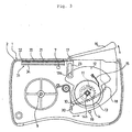
- Figs. 1 to 11 show an optical-connector cleaning device according to an embodiment of the present invention.
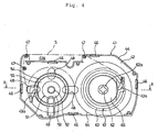
- the cleaning device of this embodiment includes an outer casing 1, shown in Figs. 1 to 3, and a cassette 41, shown in Figs. 4 to 5.
- the outer casing 1 has a configuration such that a lid 3 is connected to a casing main body 2 accommodating the cassette 41 such that it can rotate.
- the lid 3 includes a slider 5, which can be slid along a rail 4, and the slider 5 is biased in one direction by a spring 6.
- the slider 5 includes an engagement hole 5a.
- the engagement hole 5a is brought into engagement with the end of a pole 7 projecting into the interior of the casing main body 2 by an elastic force of the spring 6. Therefore, the outer casing 1 can be opened and closed by sliding the slider 5 from the exterior of the casing.
- the lid 3 includes an observation hole 8 through which the remaining amount of the cleaning tape can be checked.
- the outer casing 1 includes support shafts 9 and 10 disposed on the inside surface with a spacing therebetween.
- the support shaft 10 includes a rotating plate 12 having a pinion 11 and a drive shaft 14 having a gearwheel 13 such that they are rotatably retained.
- the rotating plate 12 includes a push plate 15 that is engageable with the gearwheel 13 of the drive shaft 14 to rotate the drive shaft 14 only in one direction when repeatedly rotating around the shaft. Since the drive shaft 14, however, is biased toward the end thereof by a spring member (not shown), the gearwheel 13 is disengaged from the push plate 15 when the cassette 41 is not mounted in the outer casing 1, and thus, the drive shaft 14 can be rotated.
- the drive shaft 14 has a plurality of projecting striations 14a extending in the axial direction on the peripheral surface thereof.
- the outer casing 1 has a lever 16 on the outer casing 1 such that it can be turned around a rotating shaft 17.
- the lever 16 has a rack 18, which is engageable with the pinion 11, integrally attached thereto.
- the rack 18 rotates the pinion 11 while being guided by a guide pin 19 by the operation of the lever 16.
- the rack 18 is biased in one direction by a spring 20, the lever 16 projects from the outer casing 1 when no cassette is loaded.
- the lever 16 is designed to have a substantially symmetrical shape with respect to the outer casing 1 so as to easily be operated irrespective of the dominant hand.
- the rotation of the lever 16 is converted to an intermittent one-directional rotation of the drive shaft 14 by a power transmission mechanism including the aforesaid rack 18, the pinion 11, the rotating plate 12, the push plate 15, and the gearwheel 13.
- the outer casing 1 includes a window 22 having a shutter 21 made of a metallic thin plate, at the upper part thereof.
- the shutter 21 has a bracket 23 having an elliptic opening at the rear end thereof, the bracket 23 being connected to a retaining section 12a of the rotating plate 12. Therefore, when the lever 16 is pushed to rotate the rotating plate 12, the shutter 21 is slid under the lever 16 to thereby open the window 22.
- the outer casing 1 includes a replacement unit 31 having a guide plate 32 for guiding the fiber end surface of the optical connector and a rubber pad 33 serving as a base for the cleaning tape, detachably mounted at a position corresponding to the window 22.
- the replacement unit 31 accommodates the rubber pad 33 in a recessed portion of a holder 34 and only one side of the guide plate 32 is fixed to the rim of the holder 34.
- the holder 34 includes an engaging piece 34a at the side thereof, which is brought into engagement with a support section 2a of the case main body 2, thereby being arranged at the position corresponding to the window 22.
- replacement units 31 are prepared, any one of which is selected depending on the type of optical connector.
- a combination of the guide plate 32 having two slits 35 and the rubber pad 33 having two grooves 36 corresponding to the slits 35 may be used.
- a combination of the guide plate 32 having one slit 35 and the rubber pad 33 having one projecting striation 37 that is narrower than the slit 35 may be used.
- Such units are effective in cleaning an optical connector having guide pins beside the fiber end surface.
- Fig. 9(a) a combination of the guide plate 32 having three slits 35 of different widths and a flat rubber pad 33 may be used. This unit can clean optical connectors of different sizes.
- the material of the rubber pad 33 is not particularly limited, it is preferable that the rubber pad has a JIS-A hardness of 55 to 80, more preferably, 60 to 80, in order that the optical-fiber cleaning effect of the cleaning tape is sufficient. If the rubber pad 33 serving as the base for the cleaning tape is too soft, this makes it difficult for the optical connector to slide on the cleaning tape, and conversely, if the rubber pad 33 is too hard, this provides an insufficient optical-connector cleaning effect.
- the cassette 41 is configured to integrally hold a reel 51 (first reel) for feeding cleaning tape S that has not been used and a reel 61 (second reel) for taking up the cleaning tape S that has been used.
- a reel 51 first reel
- a reel 61 second reel
- the cassette 41 has peripheral walls 44 and 45 attached to the edges of side plates 42 and 43, respectively, and the peripheral walls 44 and 45 are connected to each other through a plurality of connecting portions 46.
- the side wall 42 and the peripheral wall 44 may be integrally formed and the side wall 43 and the peripheral wall 45 may be integrally formed.
- the cassette 41 has a tape exposing portion 41a at the upper part thereof for exposing the cleaning tape S.
- the cleaning tape S unwound from the reel 51 passes through the tape exposing portion 41a while being guided by a plurality of rollers 47 and reaches the reel 61.
- the fiber forming the cloth is not particularly limited, however, a micro-fiber filament string having a single-fiber fineness of 0.0001 to 1.0 dtex is preferably used. Cloth made of such micro-fiber filament strings can demonstrate an excellent cleaning effect on the fiber end surface.
- the upper limit of the single-fiber fineness is more preferably 0.5 dtex or less, and more preferably 0.1 dtex or less.
- the micro-fiber filament string may be either a non-twisted thread or a twisted thread.
- the weaving structure is plain.
- the filament may have a normal circular cross section, however, it is particularly preferable that it has a modified cross-section or is crimped, thereby obtaining an improved cleaning effect.
- the reel 51 for feeding the unused cleaning tape S includes a drum 53 at the periphery of a rotating cylinder 52, around which the cleaning tape S is to be wound, and a side plate 54 and a gearwheel 55 at one end of the drum 53, and the rotating cylinder 52 is inserted into openings formed in the side plates 42 and 43, thus being allowed to rotate.
- the side plate 43 includes an engaging claw 43a that is engageable with the gearwheel 55, and the rotating direction of the reel 51 is controlled in one direction by the engaging claw 43a.
- the side plate 42 of the cassette 41 includes a plurality of openings 48, through which alcohol is injected, at positions corresponding to the cleaning tape S wound around the reel 51.
- the cleaning tape S can be impregnated with alcohol as necessary through the openings 48.
- the side plate 42 has also an observation bay window 49 for use in checking the remaining amount of the cleaning tape S.
- the observation bay window 49 is arranged to be fitted in the observation hole 8 of the outer casing 1.
- the reel 61 for taking up the used cleaning tape S has a drum 63 at the periphery of a rotating cylinder 62, around which the cleaning tape S is to be wound, and has a side plate 64 and a gearwheel 65 at one end of the drum 63, and can be rotated by inserting the rotating cylinder 62 into openings formed in the side plates 42 and 43.
- the side plate 42 includes an engaging claw 42a that is engageable with the gearwheel 65, and the rotating direction of the reel 61 is controlled in one direction by the engaging claw 42a.
- the rotating cylinder 62 of the reel 61 is fitted on the drive shaft 14 of the outer casing 1 and is driven to rotate.
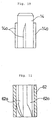
- the inner peripheral surface of the rotating cylinder 62 of the reel 61 includes a plurality of projecting striations 62a formed to extend along the axis thereof.
- the projecting striations 14a formed on the outer periphery of the drive shaft 14 each have a shape wherein the end is beveled off in the axial direction.
- the projecting striations 62a formed on the inner periphery each have a shape wherein the end is beveled off in the axial direction.
- the outer casing 1 is opened, and the cassette 41 is inserted therein.
- the rotating cylinder 52 of the reel 51 for tape feeding is fitted on the support shaft 9, while the rotating cylinder 62 of the reel 61 for taking-up the tape is fitted on the drive shaft 14.
- the cleaning tape S exposed at the tape exposing portion 41a of the cassette 41 is inserted between the guide plate 32 and the rubber pad 33 of the replacement unit 31.
- the lever 16 When the optical connector is cleaned, the lever 16 is pushed to open the shutter 21 of the window 22 and, at the same time, the reel 61 is rotated at a predetermined angle by the rotation of the drive shaft 14 to take up the cleaning tape S around the reel 61, while the unused cleaning tape S fed from the reel 51 is moved past the window 22. In this state, the optical connector is cleaned in such a way that it is rubbed on the cleaning tape S along the slit(s) 35 of the guide plate 32 with the rubber pad 33 serving as a base.
- the cleaning tape S in the cassette 41 has been used up, it is recommended that after the outer casing 1 has been opened, the cassette 41 be taken out, and then a new cassette 41 be mounted.
- the cleaning tape S can easily be replaced by replacing the whole cassette. Also, since the cleaning tape S is held in the cassette along with the reels 51 and 61, it is difficult for contaminants to stick to the cleaning tape S.
- the invention can also be applied to a cleaning device of the type in which the cleaning tape is replaced by replacing the reels.
- a replacement unit having a guide plate for guiding a fiber end surface of an optical connector and a rubber pad serving as a base for cleaning tape is detachably disposed at a position corresponding to a window in an outer casing, so that the shapes of the guide plate and the rubber pad can be varied depending on the type of optical connector.
- the outer casing includes a rotating lever and a power transmission mechanism for converting the rotation of the lever into one-directional rotation of the drive shaft and a second reel of a cassette is rotated by a predetermined rotation angle by the rotation of the drive shaft, whereby even cassette-type cleaning tape can be gradually fed without any trouble.
- the lever can be arranged symmetrically with respect to the outer casing, allowing easy operation irrespective of the dominant hand.
- the drive shaft provided in the outer casing includes a plurality of projecting striations on the outer periphery thereof extending in the axial direction thereof, and a rotating cylinder of a second reel, into which the drive shaft is to be inserted, has a plurality of projecting striations extending in the axial direction thereof, on the inner peripheral surface thereof, and the ends of which are beveled off in the axial direction, the drive shaft of the outer casing can easily enter the rotating cylinder of the second reel when mounting the cassette, thus further facilitating replacement of the cleaning tape.
- openings for alcohol injection at positions corresponding to the cleaning tape wound around the first reel of the cassette. Providing such openings allows the cleaning tape to be impregnated with alcohol if necessary.
- a replacement unit having a guide plate for guiding a fiber end surface of an optical connector and a rubber pad serving as a base for the cleaning tape is detachably disposed at a position corresponding to the window in the outer casing, the shapes of the guide plate and the rubber pad can be varied depending on the type of optical connector, thus facilitating the cleaning of optical connectors having various shapes.
- the replacement unit it is recommended that several types of replacement units be prepared and any one of the replacement units be selected depending on the type of optical connector.
- an optical-connector cleaning device in which an outer casing has an openable and closable window, through which a cleaning tape for cleaning fiber end surface of the optical connectors is gradually fed, a cassette integrally holding a first reel for feeding unused cleaning tape and a second reel for taking up the used cleaning tape is configured, and the cassette can be attached to and detached from the outer casing, thus facilitating replacement of the cleaning tape.
- the cassette integrally holds the first reel for tape feeding and the second reel for tape take-up, and can be attached to and detached from the outer casing, the cleaning tape can easily be replaced by replacing the whole cassette. Moreover, since the cleaning tape is held in the cassette along with the reel, contaminants rarely stick to the cleaning tape.
- a replacement unit having a guide plate for guiding a fiber end surface of an optical connector and a rubber pad serving as a base for the cleaning tape is detachably disposed at a position corresponding to the window in the outer casing, the shapes of the guide plate and the rubber pad can be varied depending on the type of optical connector, thus facilitating the cleaning of optical connectors having various shapes.
Landscapes
- Physics & Mathematics (AREA)
- General Physics & Mathematics (AREA)
- Optics & Photonics (AREA)
- Mechanical Coupling Of Light Guides (AREA)
- Cleaning In General (AREA)
Abstract
Description
- 1
- outer casing
- 2
- casing main body
- 2a
- support section
- 3
- lid
- 4
- rail
- 5
- slider
- 5a
- engagement hole
- 6
- spring
- 7
- pole
- 8
- observation hole
- 9
- support shaft
- 10
- support shaft
- 11
- pinion
- 12
- rotating plate
- 12a
- retaining section
- 13
- gearwheel
- 14
- drive shaft
- 14a
- projecting striation
- 15
- push plate
- 16
- lever
- 17
- rotating shaft
- 18
- rack
- 19
- guide pin
- 20
- spring
- 21
- shutter
- 22
- window
- 23
- bracket
- 31
- replacement unit
- 32
- guide plate
- 33
- rubber pad
- 34
- holder
- 34a
- engaging piece
- 35
- slit
- 36
- groove
- 37
- projecting striation
- 41
- cassette
- 41a
- tape exposing portion
- 42
- side plate
- 42a
- engaging claw
- 43
- side plate
- 43a
- engaging claw
- 44
- peripheral wall
- 45
- peripheral wall
- 46
- connecting portion
- 48
- opening
- 49
- observation bay window
- 51
- reel (first reel)
- 52
- rotating cylinder
- 53
- drum
- 54
- side plate
- 55
- gearwheel
- 61
- reel (second reel)
- 62
- rotating cylinder
- 63
- drum
- 64
- side plate
- 65
- gearwheel
- S
- cleaning tape
Claims (9)
- An optical-connector cleaning device in which an outer casing has an openable and closable window, through which a cleaning tape for cleaning fiber end surface of the optical connectors is gradually fed, comprising a cassette integrally holding a first reel for feeding unused cleaning tape and a second reel for taking up the used cleaning tape, the cassette being detachable from the outer casing.
- The optical-connector cleaning device according to claim 1, wherein a replacement unit including a guide plate for guiding the fiber end surface of the optical connector and a rubber pad serving as a base for the cleaning tape is detachably disposed at a position corresponding to the window in the outer casing.
- The optical-connector cleaning device according to claim 2, wherein several types of replacement units are provided as the replacement unit, any one of which is selected depending on the type of optical connector.
- The optical-connector cleaning device according to claim 1, wherein the outer casing includes a rotating lever and a power transmission mechanism for converting the rotation of the lever into one-directional rotation of a drive shaft, and wherein the second reel of the cassette is rotated by a predetermined angle by the rotation of the drive shaft.
- The optical-connector cleaning device according to claim 1, wherein a drive shaft provided in the outer casing has a plurality of projecting striations on the outer periphery thereof, the striations extending in the axial direction of the drive shaft, wherein a rotating cylinder of the second reel, into which the drive shaft is to be inserted, has a plurality of projecting striations on the inner periphery thereof, the striations extending in the axial direction of the rotating cylinder, and wherein the ends of the projecting striations are beveled off in the axial directions.
- The optical-connector cleaning device according to claim 1, wherein an opening for alcohol injection is formed at a position corresponding to the cleaning tape wound around the first reel of the cassette.
- An optical-connector cleaning device wherein an outer casing has an openable and closable window, through which a cleaning tape for cleaning fiber end surface of the optical connectors is gradually fed, wherein a replacement unit including a guide plate for guiding a fiber end surface of the optical connector and a rubber pad serving as a base for the cleaning tape is detachably disposed at a position corresponding to the window in the outer casing.
- The optical-connector cleaning device according to claim 7, wherein several types of replacement units are provided as the replacement unit, and wherein any one of the replacement units is selected depending on the type of optical connector.
- The optical-connector cleaning device according to claim 7, wherein the rubber pad has a JIS-A hardness of 55 to 80.
Applications Claiming Priority (5)
| Application Number | Priority Date | Filing Date | Title |
|---|---|---|---|
| JP2001009188 | 2001-01-17 | ||
| JP2001009190A JP4270359B2 (en) | 2001-01-17 | 2001-01-17 | Optical connector cleaning device |
| JP2001009188A JP4270358B2 (en) | 2001-01-17 | 2001-01-17 | Optical connector cleaning device |
| JP2001009190 | 2001-01-17 | ||
| PCT/JP2002/000071 WO2002057825A1 (en) | 2001-01-17 | 2002-01-10 | Optical connector cleaning device |
Publications (3)
| Publication Number | Publication Date |
|---|---|
| EP1300709A1 true EP1300709A1 (en) | 2003-04-09 |
| EP1300709A4 EP1300709A4 (en) | 2005-08-03 |
| EP1300709B1 EP1300709B1 (en) | 2007-04-11 |
Family
ID=26607846
Family Applications (1)
| Application Number | Title | Priority Date | Filing Date |
|---|---|---|---|
| EP02732185A Expired - Lifetime EP1300709B1 (en) | 2001-01-17 | 2002-01-10 | Optical connector cleaning device |
Country Status (3)
| Country | Link |
|---|---|
| US (1) | US7216393B2 (en) |
| EP (1) | EP1300709B1 (en) |
| WO (1) | WO2002057825A1 (en) |
Cited By (3)
| Publication number | Priority date | Publication date | Assignee | Title |
|---|---|---|---|---|
| US4840166A (en) * | 1986-04-01 | 1989-06-20 | Siemens Aktiengesellschaft | Shock wave source with increased degree of effectiveness |
| EP3000538A4 (en) * | 2014-08-13 | 2016-10-26 | Huawei Tech Co Ltd | DEVICE FOR CLEANING OPTICAL FIBER CONNECTORS |
| US9507146B2 (en) | 2014-08-13 | 2016-11-29 | Huawei Technologies Co., Ltd. | Apparatus for cleaning optical fiber connector |
Families Citing this family (8)
| Publication number | Priority date | Publication date | Assignee | Title |
|---|---|---|---|---|
| WO2005017590A1 (en) * | 2003-08-13 | 2005-02-24 | Seikoh Giken Co., Ltd. | Optical fiber connector cleaner, and method of cleaning optical fiber connector connection surface |
| US8336149B2 (en) * | 2009-02-12 | 2012-12-25 | Illinois Tool Works Inc. | Fiber optic component cleaning device with grooved platen |
| US20110303241A1 (en) * | 2010-06-14 | 2011-12-15 | Zynon Technologies, Llc | Cleaning device for optical fiber components |
| JP7120050B2 (en) * | 2019-01-25 | 2022-08-17 | 日本電信電話株式会社 | optical connector cleaner |
| WO2021029388A1 (en) * | 2019-08-14 | 2021-02-18 | 株式会社巴川製紙所 | Optical connector cleaning tool |
| US11808658B2 (en) | 2019-09-27 | 2023-11-07 | Panduit Corp. | Visual inspector attachment for fiber connector cleaners |
| US11644626B2 (en) * | 2019-09-30 | 2023-05-09 | Panduit Corp. | Fiber optic inspection tool with integrated cleaning mechanism |
| US20230204869A1 (en) * | 2020-06-01 | 2023-06-29 | Tomoegawa Co., Ltd. | Structure for attaching object to be attached and method for attaching object to be attached |
Family Cites Families (9)
| Publication number | Priority date | Publication date | Assignee | Title |
|---|---|---|---|---|
| GB2066999B (en) * | 1980-01-04 | 1984-01-04 | Allsop Inc | Video player/recorder cleaning apparatus and method |
| JPH02264907A (en) * | 1989-04-06 | 1990-10-29 | Nippon Telegr & Teleph Corp <Ntt> | Cleaning implement for optical connector |
| JP3127971B2 (en) * | 1993-02-19 | 2001-01-29 | 本多通信工業株式会社 | Optical connector cleaning device, reel structure on cleaning tape winding side, and end structure of cleaning tape |
| JP3549610B2 (en) * | 1995-04-13 | 2004-08-04 | 株式会社フジクラ | Optical fiber cleaning method and optical fiber cleaner |
| JPH09285766A (en) * | 1996-04-24 | 1997-11-04 | Nippon Telegr & Teleph Corp <Ntt> | Optical connector cleaner |
| US6191922B1 (en) * | 1996-12-26 | 2001-02-20 | Sony Corporation | Tape or disc player having a lid with a lock mechanism |
| JPH10227943A (en) * | 1997-02-14 | 1998-08-25 | Furukawa Electric Co Ltd:The | Cleaning jig for optical connector |
| US6681437B1 (en) * | 1999-04-30 | 2004-01-27 | Ntt Advanced Technology Corporation | Cleaning tool for optical fiber connectors |
| JP2003057489A (en) * | 2001-08-15 | 2003-02-26 | Ntt Advanced Technology Corp | Cleaning tool for optical connector |
-
2002
- 2002-01-10 EP EP02732185A patent/EP1300709B1/en not_active Expired - Lifetime
- 2002-01-10 US US10/221,542 patent/US7216393B2/en not_active Expired - Lifetime
- 2002-01-10 WO PCT/JP2002/000071 patent/WO2002057825A1/en not_active Ceased
Cited By (3)
| Publication number | Priority date | Publication date | Assignee | Title |
|---|---|---|---|---|
| US4840166A (en) * | 1986-04-01 | 1989-06-20 | Siemens Aktiengesellschaft | Shock wave source with increased degree of effectiveness |
| EP3000538A4 (en) * | 2014-08-13 | 2016-10-26 | Huawei Tech Co Ltd | DEVICE FOR CLEANING OPTICAL FIBER CONNECTORS |
| US9507146B2 (en) | 2014-08-13 | 2016-11-29 | Huawei Technologies Co., Ltd. | Apparatus for cleaning optical fiber connector |
Also Published As
| Publication number | Publication date |
|---|---|
| EP1300709A4 (en) | 2005-08-03 |
| US20030126707A1 (en) | 2003-07-10 |
| WO2002057825A1 (en) | 2002-07-25 |
| US7216393B2 (en) | 2007-05-15 |
| EP1300709B1 (en) | 2007-04-11 |
Similar Documents
| Publication | Publication Date | Title |
|---|---|---|
| US7216393B2 (en) | Optical connector cleaning device | |
| US6758605B1 (en) | Cleaning device and method for optical connectors | |
| US20050286853A1 (en) | Optical connector cleaning tool, cleaning tape, optical connector cleaning method, optical component cleaning tool, and optical component cleaning tool | |
| JP3350850B2 (en) | Cleaner for optical fiber connector | |
| US8079111B2 (en) | Optical connector cleaning tool and optical component cleaning tool | |
| US20100043159A1 (en) | Optical connector cleaning tool | |
| US8266755B2 (en) | Cleaning device of optical connector | |
| JP3338990B2 (en) | Cleaning system for fiber optic connectors | |
| WO2005017590A1 (en) | Optical fiber connector cleaner, and method of cleaning optical fiber connector connection surface | |
| CN100442094C (en) | Cleaner for optical fiber connector and cleaning method for connection surface of optical fiber connector | |
| US4854755A (en) | Reloadable ribbon cassette system | |
| JP4350683B2 (en) | Optical connector cleaning tool and optical component cleaning tool | |
| JP4173402B2 (en) | Optical connector cleaning tool and optical connector cleaning method | |
| JP3127971B2 (en) | Optical connector cleaning device, reel structure on cleaning tape winding side, and end structure of cleaning tape | |
| JP4270358B2 (en) | Optical connector cleaning device | |
| EP4664169A1 (en) | Optical connector cleaning tool | |
| JP4163083B2 (en) | Optical connector cleaning tool and optical component cleaning tool | |
| JP4270359B2 (en) | Optical connector cleaning device | |
| JP2009199033A (en) | Cleaner for optical fiber connector, cleaning method of ferrule end surface of optical fiber connector | |
| JP4080844B2 (en) | Optical connector cleaning tool | |
| JP3880955B2 (en) | Optical connector cleaning tool and optical connector plug cleaning method | |
| JP2004347792A (en) | Optical connector cleaning tool and optical component cleaning tool | |
| EP4726445A1 (en) | Optical connector cleaning tool | |
| JP2002090579A (en) | Optical connector cleaning equipment | |
| JP2004271765A (en) | Optical connector cleaning tool |
Legal Events
| Date | Code | Title | Description |
|---|---|---|---|
| PUAI | Public reference made under article 153(3) epc to a published international application that has entered the european phase |
Free format text: ORIGINAL CODE: 0009012 |
|
| 17P | Request for examination filed |
Effective date: 20021129 |
|
| AK | Designated contracting states |
Kind code of ref document: A1 Designated state(s): AT BE CH CY DE DK ES FI FR GB GR IE IT LI LU MC NL PT SE TR |
|
| RBV | Designated contracting states (corrected) |
Designated state(s): GB |
|
| REG | Reference to a national code |
Ref country code: DE Ref legal event code: 8566 |
|
| A4 | Supplementary search report drawn up and despatched |
Effective date: 20050617 |
|
| RIC1 | Information provided on ipc code assigned before grant |
Ipc: 7G 02B 6/36 A Ipc: 7G 02B 6/38 B Ipc: 7B 08B 1/00 B |
|
| GRAP | Despatch of communication of intention to grant a patent |
Free format text: ORIGINAL CODE: EPIDOSNIGR1 |
|
| GRAS | Grant fee paid |
Free format text: ORIGINAL CODE: EPIDOSNIGR3 |
|
| GRAA | (expected) grant |
Free format text: ORIGINAL CODE: 0009210 |
|
| AK | Designated contracting states |
Kind code of ref document: B1 Designated state(s): GB |
|
| REG | Reference to a national code |
Ref country code: GB Ref legal event code: FG4D |
|
| PLBE | No opposition filed within time limit |
Free format text: ORIGINAL CODE: 0009261 |
|
| STAA | Information on the status of an ep patent application or granted ep patent |
Free format text: STATUS: NO OPPOSITION FILED WITHIN TIME LIMIT |
|
| 26N | No opposition filed |
Effective date: 20080114 |
|
| PGFP | Annual fee paid to national office [announced via postgrant information from national office to epo] |
Ref country code: GB Payment date: 20201230 Year of fee payment: 20 |
|
| REG | Reference to a national code |
Ref country code: GB Ref legal event code: PE20 Expiry date: 20220109 |
|
| PG25 | Lapsed in a contracting state [announced via postgrant information from national office to epo] |
Ref country code: GB Free format text: LAPSE BECAUSE OF EXPIRATION OF PROTECTION Effective date: 20220109 |