EP1300586A2 - Liquid injection apparatus - Google Patents
Liquid injection apparatus Download PDFInfo
- Publication number
- EP1300586A2 EP1300586A2 EP02256849A EP02256849A EP1300586A2 EP 1300586 A2 EP1300586 A2 EP 1300586A2 EP 02256849 A EP02256849 A EP 02256849A EP 02256849 A EP02256849 A EP 02256849A EP 1300586 A2 EP1300586 A2 EP 1300586A2
- Authority
- EP
- European Patent Office
- Prior art keywords
- liquid
- injection
- section
- piezoelectric
- chamber
- Prior art date
- Legal status (The legal status is an assumption and is not a legal conclusion. Google has not performed a legal analysis and makes no representation as to the accuracy of the status listed.)
- Withdrawn
Links
Images


Classifications
-
- F—MECHANICAL ENGINEERING; LIGHTING; HEATING; WEAPONS; BLASTING
- F02—COMBUSTION ENGINES; HOT-GAS OR COMBUSTION-PRODUCT ENGINE PLANTS
- F02M—SUPPLYING COMBUSTION ENGINES IN GENERAL WITH COMBUSTIBLE MIXTURES OR CONSTITUENTS THEREOF
- F02M61/00—Fuel-injectors not provided for in groups F02M39/00 - F02M57/00 or F02M67/00
- F02M61/16—Details not provided for in, or of interest apart from, the apparatus of groups F02M61/02 - F02M61/14
- F02M61/18—Injection nozzles, e.g. having valve seats; Details of valve member seated ends, not otherwise provided for
- F02M61/1853—Orifice plates
- F02M61/186—Multi-layered orifice plates
-
- F—MECHANICAL ENGINEERING; LIGHTING; HEATING; WEAPONS; BLASTING
- F02—COMBUSTION ENGINES; HOT-GAS OR COMBUSTION-PRODUCT ENGINE PLANTS
- F02M—SUPPLYING COMBUSTION ENGINES IN GENERAL WITH COMBUSTIBLE MIXTURES OR CONSTITUENTS THEREOF
- F02M51/00—Fuel-injection apparatus characterised by being operated electrically
- F02M51/06—Injectors peculiar thereto with means directly operating the valve needle
- F02M51/0603—Injectors peculiar thereto with means directly operating the valve needle using piezoelectric or magnetostrictive operating means
-
- F—MECHANICAL ENGINEERING; LIGHTING; HEATING; WEAPONS; BLASTING
- F02—COMBUSTION ENGINES; HOT-GAS OR COMBUSTION-PRODUCT ENGINE PLANTS
- F02M—SUPPLYING COMBUSTION ENGINES IN GENERAL WITH COMBUSTIBLE MIXTURES OR CONSTITUENTS THEREOF
- F02M51/00—Fuel-injection apparatus characterised by being operated electrically
- F02M51/06—Injectors peculiar thereto with means directly operating the valve needle
- F02M51/061—Injectors peculiar thereto with means directly operating the valve needle using electromagnetic operating means
-
- F—MECHANICAL ENGINEERING; LIGHTING; HEATING; WEAPONS; BLASTING
- F02—COMBUSTION ENGINES; HOT-GAS OR COMBUSTION-PRODUCT ENGINE PLANTS
- F02M—SUPPLYING COMBUSTION ENGINES IN GENERAL WITH COMBUSTIBLE MIXTURES OR CONSTITUENTS THEREOF
- F02M61/00—Fuel-injectors not provided for in groups F02M39/00 - F02M57/00 or F02M67/00
- F02M61/04—Fuel-injectors not provided for in groups F02M39/00 - F02M57/00 or F02M67/00 having valves, e.g. having a plurality of valves in series
- F02M61/047—Fuel-injectors not provided for in groups F02M39/00 - F02M57/00 or F02M67/00 having valves, e.g. having a plurality of valves in series the valves being formed by deformable nozzle parts, e.g. flexible plates or discs with fuel discharge orifices
-
- F—MECHANICAL ENGINEERING; LIGHTING; HEATING; WEAPONS; BLASTING
- F02—COMBUSTION ENGINES; HOT-GAS OR COMBUSTION-PRODUCT ENGINE PLANTS
- F02M—SUPPLYING COMBUSTION ENGINES IN GENERAL WITH COMBUSTIBLE MIXTURES OR CONSTITUENTS THEREOF
- F02M61/00—Fuel-injectors not provided for in groups F02M39/00 - F02M57/00 or F02M67/00
- F02M61/16—Details not provided for in, or of interest apart from, the apparatus of groups F02M61/02 - F02M61/14
- F02M61/166—Selection of particular materials
-
- F—MECHANICAL ENGINEERING; LIGHTING; HEATING; WEAPONS; BLASTING
- F02—COMBUSTION ENGINES; HOT-GAS OR COMBUSTION-PRODUCT ENGINE PLANTS
- F02M—SUPPLYING COMBUSTION ENGINES IN GENERAL WITH COMBUSTIBLE MIXTURES OR CONSTITUENTS THEREOF
- F02M61/00—Fuel-injectors not provided for in groups F02M39/00 - F02M57/00 or F02M67/00
- F02M61/16—Details not provided for in, or of interest apart from, the apparatus of groups F02M61/02 - F02M61/14
- F02M61/18—Injection nozzles, e.g. having valve seats; Details of valve member seated ends, not otherwise provided for
- F02M61/1806—Injection nozzles, e.g. having valve seats; Details of valve member seated ends, not otherwise provided for characterised by the arrangement of discharge orifices, e.g. orientation or size
-
- F—MECHANICAL ENGINEERING; LIGHTING; HEATING; WEAPONS; BLASTING
- F02—COMBUSTION ENGINES; HOT-GAS OR COMBUSTION-PRODUCT ENGINE PLANTS
- F02M—SUPPLYING COMBUSTION ENGINES IN GENERAL WITH COMBUSTIBLE MIXTURES OR CONSTITUENTS THEREOF
- F02M69/00—Low-pressure fuel-injection apparatus ; Apparatus with both continuous and intermittent injection; Apparatus injecting different types of fuel
- F02M69/04—Injectors peculiar thereto
- F02M69/041—Injectors peculiar thereto having vibrating means for atomizing the fuel, e.g. with sonic or ultrasonic vibrations
-
- F—MECHANICAL ENGINEERING; LIGHTING; HEATING; WEAPONS; BLASTING
- F02—COMBUSTION ENGINES; HOT-GAS OR COMBUSTION-PRODUCT ENGINE PLANTS
- F02M—SUPPLYING COMBUSTION ENGINES IN GENERAL WITH COMBUSTIBLE MIXTURES OR CONSTITUENTS THEREOF
- F02M61/00—Fuel-injectors not provided for in groups F02M39/00 - F02M57/00 or F02M67/00
- F02M61/16—Details not provided for in, or of interest apart from, the apparatus of groups F02M61/02 - F02M61/14
- F02M61/18—Injection nozzles, e.g. having valve seats; Details of valve member seated ends, not otherwise provided for
- F02M61/1853—Orifice plates
Definitions
- the present invention relates to a liquid injection apparatus for application in various types of machines that utilize liquid materials, fuel and the like injected into a liquid injection space, and for atomizing and injecting liquid into the liquid injection space, and to a method of adjusting the resonance frequency of an injection unit included in the liquid injection apparatus.
- a fuel injection apparatus for an internal combustion engine As a liquid injection apparatus of this kind, a fuel injection apparatus for an internal combustion engine has been known.
- the fuel injection apparatus for an internal combustion engine is what is called an electrically controlled fuel injection apparatus that has a pressurizing pump for pressurizing liquid, and an electromagnetic injection valve, and is widely in practical use.
- the size of liquid droplets of the injected fuel is, generally, about 100 ⁇ m at the minimum, which is relatively large, and the size is not uniform.
- Such a size of liquid droplets of the fuel and the ununiformity of the size increase unburnt fuel at the time of combustion, and further lead to the increase of undesirable exhaust gas.
- a liquid droplet ejecting apparatus in which liquid in a liquid supply passage is pressurized by the actuation of a piezoelectrostrictive element and the liquid is ejected as micro liquid droplets from the eject port.
- Such an apparatus utilizes the principle of an ink jet eject apparatus disclosed in, for example, Japanese Patent Application Laid-open ( kokai ) No. 6-40030, and is thus capable of making the ejected liquid droplets (liquid droplets of injected fuel) small and uniform as compared with the electrically controlled fuel injection apparatus, and therefore this apparatus can be considered to be an excellent apparatus in terms of fuel atomization.
- the apparatus When the ink jet eject apparatus is used in a relatively stationary surrounding environment with little change in temperature, pressure or the like (e.g., in the rooms of offices, schools and the like), the apparatus is capable of attaining expected performance of injecting liquid as micro particles.
- the apparatus when used in a surrounding environment that changes severely in accordance with the changes in operating conditions or the like, as in the internal combustion engine, it is generally difficult for the apparatus to sufficiently achieve the performance of atomizing fuel. Therefore, in the present situation, such a liquid (fuel) injection apparatus has not been provided yet that utilizes the principle of the ink jet eject apparatus and is capable of injecting liquid with sufficiently achieving the atomization of the liquid, for use in the mechanical apparatus such as the internal combustion engine used in the surrounding environment which changes severely.
- a liquid injection apparatus comprising an injection unit which comprises a flow passage forming section, the flow passage forming section including a liquid ejection nozzle having one end exposed to a liquid injection space and a chamber which communicates with the other end of the liquid ejection nozzle and with one end of a first liquid supply pipe; drive voltage generating means for generating a drive voltage signal having a predetermined frequency; and pressurizing means having an ejection section to which is connected the other end of the first liquid supply pipe, the pressurizing means having an introduction section in communication with a liquid storage tank, the pressurizing means pressurizing liquid introduced through the introduction section from the liquid storage tank to eject the liquid from the ejection section, to thereby inject the liquid into the liquid injection space through the liquid ejection nozzle of the liquid injection unit; wherein the injection unit comprises a plurality of the liquid ejection nozzles, the injection unit having a pressurizing section which includes a piezoelectric
- liquid pressurized by pressurizing means is injected from a plurality of liquid ejection nozzles, so that even if air bubbles are generated in the liquid, the air bubbles are divided into minute pieces.
- the actuation of the piezoelectric/electrostrictive element changes the capacity of chambers, which gives vibration energy (this can also be referred to simply as "vibrations".) to the liquid to be injected, the liquid is injected as liquid droplets in the form of fine particles from the liquid ejection nozzles.
- the size of the liquid droplets in the form of fine particles varies depending upon physicalities such as the pressure applied to the liquid, the amplitude and frequency of vibrations of the piezoelectric/electrostrictive element, the shape of a flow passage, the size of the flow passage, and the viscosity (consistency) and surface tension of the liquid. If a period of vibrations added to liquid is shorter than the time in which, in the vicinity of an end portion (an opening exposed to the liquid injection space) of the liquid ejection nozzle inside this nozzle, the liquid moves by a distance equivalent to the diameter of the end portion of the nozzle, the size of the liquid droplets to be injected is approximately smaller than the diameter of the end portion of the liquid ejection nozzle.
- the liquid injection apparatus can inject liquid droplets that are made minute in a significantly uniform state.
- the apparatus when used as a fuel injection apparatus for an internal combustion engine, the apparatus can form the fuel to be injected into fine particles of liquid droplets having an appropriate diameter, thereby accomplishing improvement in the fuel consumption of the internal combustion engine and a reduction of undesirable exhaust gas.
- the pressure necessary for the injection of liquid is generated by the pressurizing means, and if the environment (e.g., pressure and temperature) in the liquid injection space changes severely due to changes of operating conditions and the like of a machine to which the liquid injection apparatus is applied, it is still possible to stably inject and supply the liquid in the form of desired micro particles.
- the flow volume of fuel (liquid) is determined in accordance with air current velocity (air flow speed) in a space inside a suction pipe, which gives a liquid droplet eject space (liquid injection space), and the degree of atomization is changed depending upon the air current velocity.
- air current velocity air flow speed
- liquid injection space liquid injection space
- the liquid injection apparatus in accordance with the present invention does not have to require a compressor for supplying assist air, unlike conventional apparatuses that encourage the atomization of fuel by supplying assist air to a nozzle section of a fuel injector, thereby making the apparatus inexpensive.
- the liquid injection apparatus further comprise an injection valve including a liquid injection opening exposed to the liquid injection space, a liquid passage communicating with the liquid injection opening, and an electromagnetic valve for opening and closing the liquid passage; and a second liquid supply pipe for placing the liquid passage of the injection valve in communication with the ejection section of the pressurizing means.
- liquid can be injected through the second liquid supply pipe and the injection valve that provides a different course (passage, system) than one which passes through the first liquid supply pipe and the injection unit, so that a great volume of liquid can be injected as required.
- the liquid injection apparatus further comprise a regulator which is interposed in the first liquid supply pipe, for reducing the pressure of liquid generated by the pressurizing means.
- the liquid injection apparatus employing the injection unit forms liquid into fine particles by the actuation of the piezoelectric/electrostrictive element, and thus does not need high pressure to form the liquid into fine particles, therefore, the pressure that the pressurizing means is required to generate is naturally low.
- the pressurizing means it is possible to employ, for example, an inexpensive low-pressure pump that generates pressure of less than several atmospheres.
- the ratio of the capacity of the chamber to the variation of the capacity of the chamber (i.e. the amount of capacity change) caused by the operation of the piezoelectric/electrostrictive element is preferably a value ranging from 2 to 3000 inclusive.
- the ratio (chamber capacity/capacity variation) is beyond 3000, the energy amount of vibrations transmitted to the liquid inside the chamber is too small, making it impossible to sufficiently form the liquid into fine particles, and if the ratio (chamber capacity/capacity variation) is two or less, the pressure of the liquid in the chamber changes significantly, thus making a eject amount (injection flow volume) unstable, and if the liquid is volatile as gasoline fuel, stable injection might be impossible because a large quantity of the air bubbles is generated in the liquid. More preferably, the ratio (chamber capacity/capacity variation) is two or more and 1500 or less.
- the chamber include a flow passage section through which the liquid flows from the side of the first liquid supply pipe toward the side of the liquid ejection nozzle, the shape of a section of the flow passage section taken along a plane orthogonal to the direction of flow of the liquid (in the flow passage section) is being substantially rectangular, and that the plezoelectric/electrostrictive element be fixed in at least a part of the wall surface of the chamber that includes at least one side of the rectangle, with the ratio of the length of a side orthogonal to the one side to the length of the one side being less than 1.
- the chamber include a flow passage section which communicates, at one end portion, with one end of the first liquid supply pipe via a liquid introduction hole, the flow passage section being connected, at the other end portion, to the other end of the liquid ejection nozzle such that the liquid flows from the one end portion toward the other end portion, and that the area of the section of the flow passage section taken along the plane orthogonal to the direction of flow of the liquid be larger than the cross section area of the liquid introduction hole and than the cross section area at one end exposed to the liquid injection space of the liquid ejection nozzle.
- the chamber is constituted as described above, it is possible not only to efficiently transmit the energy of vibrations by the piezoelectric/electrostrictive element to the liquid flowing in the chamber, but also to transmit the energy of the vibrations to the entire liquid, thereby ensuring the liquid to be atomized regardless of the kind of liquid.
- the cross section area at one end exposed to the liquid injection space of the liquid ejection nozzle is preferably larger than the cross section area of the liquid introduction hole.
- the vibration energy of the piezoelectric/electrostrictive element added to the liquid in the chamber is transmitted to liquid in the first liquid supply pipe via the liquid introduction hole and is damped in the first liquid supply pipe. Therefore, the vibration energy is efficiently transmitted to the liquid ejected from one end of the liquid ejection nozzle, thereby ensuring the liquid to be atomized.
- the injection unit comprise an electromagnetic open-close valve having a liquid passage and an electromagnetic valve for opening and closing the liquid passage, the electromagnetic open-close valve being disposed to place one end of the first liquid supply pipe in communication with the chamber by way of the liquid passage, and the liquid is injected from the liquid ejection nozzle when the electromagnetic valve of the electromagnetic open-close valve is opened.
- the electromagnetic open-close valve such as an electromagnetic fuel injection valve that has conventionally been widely adopted in the fuel injection apparatus for an internal combustion engine
- the injection amount is precisely controlled in addition to the atomization of the liquid, thereby further ensuring improvement in the fuel consumption of the internal combustion engine and a reduction of undesirable exhaust gas from the internal combustion engine.
- any of the above liquid injection apparatus preferably further comprises an electromagnetic open-close valve which is interposed in the first liquid supply pipe, for opening and closing the flow passage of the fist liquid supply pipe; and a bypass pipe which makes the liquid storage tank communicate with the fist liquid supply pipe at between the electromagnetic open-close valve of the fist liquid supply pipe and the ejection section of the pressurizing means, in parallel with the pressurizing means, the bypass pipe having a check valve interposed therein for permitting liquid to flow from the fist liquid supply pipe to the liquid storage tank, only when the pressure of the liquid in the fist liquid supply pipe at between the electromagnetic open-close valve and the ejection section of the pressurizing means is beyond a predetermined value.
- the injection unit by controlling the electromagnetic open-close valve, so that, synergistically with the effects of forming liquid into fine particles, for example, when the liquid injection apparatus having such a composition is used as the fuel injection apparatus for an internal combustion engine, improvement in the fuel consumption and a reduction of undesirable exhaust gas can be further ensured.
- the bypass pipe returns the liquid to the liquid storage tank to enable the pressure to be decreased to the predetermined pressure or less, thereby making it possible to prevent breakage of the apparatus, unnecessary liquid leakage and the like.
- the flow passage forming section of the injection unit of any of the above liquid injection apparatuses is preferably formed of zirconia ceramics.
- the flow passage forming section of the injection unit and the piezoelectric/electrostrictive element of the pressurizing section are preferably integrally formed by burning.
- the injection unit that comprises the flow passage forming section capable of maintaining high durability against frequent deformation of a wall surface caused by the piezoelectric/electrostrictive element, and that has a plurality of liquid ejection nozzles, in such a small size, with a full length of several centimeters.
- the flow passage forming section can be formed easily by integrally burning the ceramics, and the pressurizing section, which includes the piezoelectric/electrostrictive element, can be joined easily and firmly to the flow passage forming section by burning, thereby securely ensuring the transmission of the force generated by the pressurizing section to the chamber.
- the flow passage forming section and the pressurizing section are made as separate members, and the piezoelectric/electrostrictive element of the pressurizing section is bonded to the flow passage forming section (without burning).
- the flow passage forming section and the piezoelectric/electrostrictive element of the pressurizing section are not burnt integrally, it is possible to have a wider range for selecting materials for a member (diaphragm) that constitutes the wall surface of the flow passage forming section, especially of the chamber.
- the wall surface member of the chamber can be formed not only of ceramics such as zirconia, but also of materials other than ceramics, and therefore, for example, if the wall surface of the chamber is formed of a metallic material having good tenacity, durability of the injection unit can be improved.
- the material of the piezoelectric/electrostrictive element which is included in the pressurizing section, does not permeate by burning into the wall (surface) of the chamber, which is part of the flow passage forming section, and therefore does not decrease the tenacity of the injection unit.
- the wall surface member of the chamber is constituted of ceramics
- the injection unit having excellent durability can be provided.
- materials for the flow passage forming section besides ceramics would include iron materials such as stainless steels of various kinds (SUS) or spring steel products of various kinds, and non-iron materials such as beryllium copper, phosphor bronze, nickel and a nickel iron alloy.
- the pressurizing section preferably presses the wall surface of the chamber in the flow passage forming section to change the capacity of the chamber.
- the pressing force of the piezoelectric/electrostrictive element deforms the wall surface of the chamber, the capacity of the chamber can certainly be changed for a long period of time regardless of the adhesion strength between the piezoelectric/electrostrictive element and the flow passage forming section, thereby making it possible to provide the liquid injection apparatus with excellent durability.
- the pressurizing section include a plate made of ceramics which has the rigidity higher than that of the chamber wall (chamber upper wall) pressed by the pressurizing section and which is immovably fixed to the flow passage forming section apart a predetermined distance from the wall surface of the chambers (when the chamber wall is not deformed by the pressurizing section), and that the piezoelectric/electrostrictive element be formed in a shape of a thin plate (a layer, a laminate), and at one surface, be integrally joined by burning to the ceramic plate, and at the other surface, be bonded to the chamber wall surface pressed by the pressurizing section.
- the piezoelectric/electrostrictive element joined integrally to the ceramic plate by burning repeatedly presses the wall (wall surface on which the piezoelectric/electrostrictive element is formed) of the chamber that functions as the diaphragm, thereby adding vibrations to the liquid in the chamber to form the liquid to be injected into fine particles.
- parts that are substantially relating to the vibrations caused by the piezoelectric/electrostrictive element include the chamber, the wall (surface) of the chamber, the piezoelectric/electrostrictive element and the ceramic plate, and the rigidity of the ceramic plate is high, resonance frequency of a part constituted of these parts is increased.
- the wall of the chamber functioning as the diaphragm is vibrated at a frequency lower than the resonance frequency, the wall of the chamber functioning as the diaphragm is deformed only from a nodal line (line of intersection) of (between) the wall and other walls (wall surfaces) of the chamber. That is, a node of the vibrations of the wall is the nodal line (the wall (wall surface) functioning as the diaphragm is deformed to have a single abdomen).
- the vibrations necessary to inject the liquid as fine particles having a desired particle diameter are added to the liquid.
- the wall (surface) of the chamber functioning as the diaphragm is vibrated by the piezoelectric/electrostrictive element at a frequency higher than the resonance frequency of the parts substantially relating to the vibrations, the wall (surface) is deformed to have a plurality of wave fronts, and it will be difficult to add to the liquid the vibrations for forming the injected liquid into the fine particles having a desired small particle diameter.
- the pressurizing section is preferably comprised of a layer which includes a multiplicity of alternating laminal piezoelectric/electrostrictive elements and laminal electrodes.
- the force (deforming force, pressurizing force) of the pressurizing section to deform the wall (surface) of the chamber can be increased even at (with) a low voltage.
- the displacement amount of the wall surface of the chamber (capacity variation of the chamber) can be increased.
- the aspect of the present invention described above can decrease the power consumption of the liquid injection apparatus.
- the wall surface of the chamber can be deformed as much as desired and the desirable capacity variation of the chamber can be ensured, since the force to deform the wall (surface) of the chamber can be made large enough. Therefore, since the liquid to be injected can be pressurized in a manner that it can be atomized even if the width and/or length of the wall (surface) of the chamber are/is reduced, the injection unit can be miniaturized.
- the chamber be connected to one end of the first liquid supply pipe via the liquid introduction hole, and that the drive voltage generating means increase the voltage of the drive voltage signal up to a predetermined voltage to decrease the capacity of the chamber so that the pressure of liquid in the chamber and in the liquid introduction hole is increased, then maintain the voltage at the predetermined voltage until the pressure of the liquid in the liquid introduction hole substantially drops down to the pressure generated by the pressurizing means, and then decrease the voltage.
- the liquid injection apparatus of the present invention comprises the piezoelectric/electrostrictive element and the pressurizing means capable of pressurizing liquid
- both the pressure increase caused by the piezoelectric/electrostrictive element and the pressure increase caused by the pressurizing means are superposed in the liquid introduction hole immediately after the pressurizing operation of the piezoelectric/electrostrictive element, and thus the pressure of the liquid in the liquid introduction hole (section) is significantly increased. Therefore, if the voltage of the drive voltage signal starts to be decreased immediately after this state (i.e. interposing both pressure) is obtained, pressure change of the liquid in the liquid introduction hole is so rapid that the air bubbles might be generated.
- the voltage is kept at the predetermined voltage until the pressure of the liquid in the liquid introduction hole substantially lowers down to the pressure generated by (only) the pressurizing means after the pressure of the liquid in the chamber and in the liquid introduction hole is increased by increasing the voltage of the drive voltage signal given to the piezoelectric/electrostrictive element to a predetermined voltage as described above, and if the voltage is started to be decreased after the pressure of the liquid in the liquid introduction hole substantially lowers down to the pressure generated by the pressurizing means, the pressure in the liquid introduction hole does not change abruptly so that the air bubbles are not generated, thereby making it possible to inject the liquid stably.
- the liquid injection apparatus is preferably configured such that a frequency of the drive voltage signal is substantially equal to a resonance frequency of the injection unit.
- the wall (surface) of the injection unit can be greatly vibrated with a little energy, the power consumption of the liquid injection apparatus can be reduced.
- the injection unit preferably comprises a plurality of the chambers, at least one of the plurality of chambers comprising a plurality of liquid ejection nozzles.
- the liquid injection apparatus capable of injecting a large amount of liquid droplets having a uniform and minute particle diameter at a time, without changing (increasing) the size of the injection unit.
- the shape of the liquid injection opening which is one end of the liquid ejection nozzle exposed to the liquid injection space is a shape having a major axis and a minor axis such as a substantial elliptical shape , an elongated circle shape, a substantial oval shape, and a substantial rectangular shape.
- the cross section area of the liquid injection opening having a shape selected from any one of a substantially ellipse shape, substantially oval shape and substantially rectangular shape is the same as the cross section area of the liquid injection opening having a circular shape, minor axes of the ellipse, oval or rectangle is shorter than the diameter of the circle, and a minimum diameter of a constriction (a constriction portion) of the ejected liquid made by the vibrations added to the liquid in the chamber is smaller than that in the case where the shape of the liquid injection opening is circular. Further, liquid has properties of becoming spherical by surface tension in space.
- liquid which is ejected from the liquid injection opening having a shape selected from any one of the substantially ellipse shape, substantially oval shape and substantially rectangular shape, separates at (from) the minimum diameter portion (i.e the constriction portion) that is smaller than in the case where the shape of the liquid injection opening is circular, and becomes spherical fine particles having a reduced diameter.
- the liquid is further atomized.
- the shape of the liquid injection opening is the shape having a major axis and a minor axis such as the substantially ellipse shape
- the minor axis of the substantially ellipse shape or the like may be the same as the diameter of the circular shape.
- the major axis can be larger than the diameter of the circular shape, and thus the area of the liquid injection opening can be enlarged.
- the amount of the injected liquid (eject flow volume) can be increased.
- any of the above liquid injection apparatuses is preferably configured such that the injection unit comprises an air nozzle (air current nozzle) having its one end exposed to the liquid injection space to inject not only liquid via the liquid ejection nozzle but also air (gas) via the air nozzle.
- air current nozzle air current nozzle
- atomized liquid droplets which does not have the inclination to move straight in the form of fine particles, can be transported to a desired position and in a desired direction by means of the air current (this may be called "air flow") formed by injected air (gas). It is also possible to prevent the liquid droplets from drifting at the same region to recombine (join together). That is, it is possible to prevent the particle diameter of the injected droplets from being larger by recombination of the droplets.
- the one end exposed to the liquid injection space of the liquid ejection nozzle preferably provides a liquid injection opening on the undersurface of the injection unit
- the one end of the air nozzle preferably provides a gas injection opening on the undersurface of the injection unit.
- the injection unit of the liquid injection apparatus have a plurality of the liquid injection openings and a plurality of the gas injection openings, and that the liquid injection openings and the gas injection openings be arranged alternately (on the undersurface of the injection unit).
- an injection current of the liquid and an injection current of the air (gas) are next to each other, so that the liquid film can be removed more effectively, and the air current enables the liquid droplets to be transported to the desired position and in the desired direction more effectively.
- the liquid injection openings and the gas injection openings are arranged on lattice points of a tetragonal lattice (this may be a rectangular lattice).
- the gas injection opening be disposed on the lattice point which is adjacent ,at(with) a shortest distance, to one of the liquid injection openings (disposed on another lattice point).
- the line be arranged in a way that it becomes the line having one kind of injection port different from the other kind of injection port that an adjacent line has (i.e., in a way that the array of the liquid injection openings is disposed between the arrays of the gas injection openings).
- the liquid injection apparatus having the air nozzle preferably employs injection control means for starting gas injection via the air nozzle before the start of liquid injection via the liquid ejection nozzle, and for stopping the gas injection via the air nozzle after ending of the liquid injection via the liquid ejection nozzle.
- injection control means for starting gas injection via the air nozzle before the start of liquid injection via the liquid ejection nozzle, and for stopping the gas injection via the air nozzle after ending of the liquid injection via the liquid ejection nozzle.
- the liquid injection apparatus having the air nozzle is preferably configured such that the injection unit comprises an air current direction control wall for controlling the gas direction by the air nozzle.
- the direction control wall With this direction control wall, the direction of the air current can be controlled, so that the moving direction of the liquid droplets transported by the air current can be brought in a desired direction.
- one end of the air nozzle is preferably disposed between one end of the liquid ejection nozzle (liquid injection opening) and the air current direction control wall (more specifically, between one end of the liquid ejection nozzle and a nodal line defined by the air current direction control wall and the undersurface of the injection unit).
- the injected liquid droplets are prevented from sticking or adhering to the air current direction control wall.
- one end (liquid injection opening) of the liquid ejection nozzle and one end (gas injection opening) of the air nozzle are arranged alternately on the undersurface of the injection unit in order to transport the liquid droplets efficiently by the air current.
- the liquid ejection nozzle and the air nozzle inject respectively liquid and gas (air) in parallel with (in a parallel direction with) each other.
- the injection of the liquid can easily ride (be transported by) the air current.
- the liquid injection apparatus used in the method comprises (1) an injection unit including a liquid ejection nozzle, one end of which is exposed to a liquid injection space, a chamber communicating with the other end of the liquid ejection nozzle and one end of a first liquid supply pipe, a lower electrode formed on a wall surface of the chamber, an upper electrode formed opposite to the lower electrode, and a piezoelectric/electrostrictive element formed between the lower electrode and the upper electrode, (2) drive voltage generating means for providing a drive voltage signal having a predetermined frequency across the upper electrode and the lower electrode to thereby give an electric field to the piezoelectric/electrostrictive element, to cause vibration of the wall of the chamber by actuating the piezoelectric/electrostrictive element, and (3) pressurizing means having an ejection section to which is connected the other end of the first liquid supply pipe and also having an introduction section communicating with a liquid storage
- the method comprises trimming part of the upper electrode to change a region of the piezoelectric/electrostrictive element to which the electric field is applied by the upper electrode and the lower electrode, and thereby adjusting the resonance frequency of the injection unit to be substantially equal to a frequency in the vicinity of the frequency of the drive voltage signal.
- the resonance frequency of the injection unit substantially equal to the frequency of the drive voltage signal easily by trimming the upper electrode with a laser or the like.
- the apparatus including a plurality of chambers it is possible to easily adjust the resonance frequencies between each of the chambers about the same, so that it is not necessary to comprise drive voltage generating means for generating the drive voltage signals having different frequencies for each of the chambers.
- the apparatus be less expensive.
- the liquid injection apparatus 10 comprises a pressurizing pump 11 (in this embodiment, a low-pressure pump 11) serving as pressurizing means; a first liquid supply pipe 12 serving as a first liquid supply passage; a filter 13 to which one end of the first liquid supply pipe 12 is connected for removing dust and foreign objects in the liquid; an injection unit (spray unit) 14 which communicates with one end of the first liquid supply pipe 12 via the filter 13 and comprises a plurality of chambers, each of the chambers having at least a piezoelectric/electrostrictive element formed on its outer wall surface of the chamber and a plurality of ejection nozzles to form the injected liquid into fine particles; and an eject pipe 15 for connecting the injecting unit 14 to the suction pipe 20.
- a pressurizing pump 11 in this embodiment, a low-pressure pump 11
- a first liquid supply pipe 12 serving as a first liquid supply passage
- a filter 13 to which one end of the first liquid supply pipe 12 is connected for removing dust and foreign objects in the liquid
- the pressurizing pump 11 comprises a introduction section 11a which communicates with a bottom portion of a liquid storage tank 22 and to which liquid is supplied from the liquid storage tank 22, and an ejection section 11b connected to the other end of the first liquid supply pipe 12.
- This pressurizing pump 11 pressurizes the liquid introduced through the introduction section 11a from the liquid storage tank 22 up to a pressure that enables the liquid to be injected into the liquid injection space 21 via the injection unit 14 (even if the piezoelectric/electrostrictive element of the injection unit 14 is not actuated(operated)), and feeds (ejects) the liquid from the ejection section 11b to the first liquid supply pipe 12.
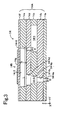
- the injection unit 14 as shown in Fig. 2 being its plan view and in Fig. 3 being a sectional view of the injection unit 14 taken along line 1-1 of Fig. 2, has a substantially rectangular parallelepiped shape whose sides extend in parallel with the corresponding orthogonal X, Y, and Z axes.
- the injection unit 14 includes a flow passage forming section 14A comprising a plurality of ceramics thin plates (laminates, hereinafter referred to as "ceramic sheets") 14a to 14f that are pressed (layered) and stuck by pressure, and a pressurizing section 14B comprising a piezoelectric/electrostrictive element 14g fixed onto an exterior surface (plane along an X-Y plane in Z axis positive direction) of the ceramic sheet 14f.
- a flow passage forming section 14A comprising a plurality of ceramics thin plates (laminates, hereinafter referred to as "ceramic sheets”) 14a to 14f that are pressed (layered) and stuck by pressure
- a pressurizing section 14B comprising a piezoelectric/electrostrictive element 14g fixed onto an exterior surface (plane along an X-Y plane in Z axis positive direction) of the ceramic sheet 14f.
- This injection unit 14 comprises therein a liquid supply passage 14-1, a plurality (herein seven) of chambers 14-2 being mutually independent, a plurality of liquid introduction holes 14-3 having each of the chambers 14-2 communicate with the liquid supply passage 14-1, a plurality of liquid ejection nozzles 14-4 (each one end of the nozzles is substantially exposed to the liquid injection space 21 via the eject pipe 15 in a way that each of the chambers 14-2 communicates with an outer portion of the injection unit 14), and a liquid fill port 14-5 to which the filter 13 is coupled.
- the liquid supply passage 14-1 is a cutout space whose shape is an elongated circle of which major and minor axes are in parallel with the X and Y axes, respectively, and which is defined by a cutout wall surface (a side wall surface) in the ceramic sheet 14c, an top (upper) surface of the ceramic sheet 14b, and an undersurface (a lower surface) of the ceramic sheet 14d.
- the liquid supply passage 14-1 communicates with the liquid storage tank 22 via the liquid fill port 14-5, the filter 13, the first liquid supply pipe 12, and the pressurizing pump 11.
- the liquid to be injected (sprayed) is supplied to the liquid supply passage 14-1 with being pressurized by the pressurizing pump 11.
- Each of the plurality of chambers 14-2 is a space having a longer axis and a shorter axis (a liquid flow passage portion having a elongated longitudinal axis), the space being defined by the side wall surface of a cutout space, formed in the ceramic sheet 14e, of which shape is an elongated circle whose major and minor axes are in parallel with Y axis direction and an X axis direction, respectively, an top surface (upper surface) of the ceramic sheet 14d, and an undersurface (lower surface) of the ceramic sheet 14f.
- One end of each of the chambers 14-2 in the Y positive direction extends up to an upper portion of the liquid supply passage 14-1.
- Each of the chambers 14-2 communicates with the liquid supply passage 14-1 by means of the liquid introduction hole 14-3 which is formed in the ceramic sheet 14d and has a hollow cylindrical shape having a diameter d.
- the diameter d will also be simply referred to as "introduction hole diameter d".
- the other end of each of the chambers 14-2 in the Y negative direction is connected to the other end of the liquid ejection nozzle 14-4. With this configuration, the liquid flows in the flow passage portion from the first liquid supply pipe 12 side to the liquid ejection nozzle 14-4 side.
- Each of the liquid ejection nozzles 14-4 is a hollow cylindrical through-hole.
- the liquid ejection nozzles 14-4 is formed and comprised of one end (a liquid injection opening (port), an opening or an opening portion exposed to the liquid injection space, ejection hole) 14-4a, having a diameter D, formed in the ceramic sheet 14a, which is substantially exposed to the liquid injection space 21, and hollow cylindrical communicating holes 14-4b to 14-4d that are formed in ceramic sheets 14b to 14d whose sizes (diameters) become larger in order from the liquid injection opening 14-4a to the chamber 14-2, respectively.
- the axis line of each of the liquid ejection nozzles 14-4 is in parallel with Z axis.
- the diameter D will also be simply referred to as "nozzle diameter D".
- each of the chambers 14-2 in each of the chambers 14-2, at their central portion (flow passage portion), the shape of a cross section of the flow passage taken along a plane which is orthogonal to (runs at right angles to) the flowing direction of the liquid is substantially quadrangle (rectangular).
- a major axis L (length along Y axis) and a minor axis W (length along X axis, i.e. length of one side of the quadrangle ) of the long-shape flow passage portion have lengths of 3.5 mm and 0.35 mm, respectively, and its height T (length along Z axis, i.e.
- This ratio (T/W) is preferably of a value of 0 or more and 1 or less.
- the diameter D of the end portion 14-4a of the liquid ejection nozzle and the diameter d of the liquid introduction hole 14-3 are 0.031 mm and 0.025 mm ,respectively.
- the cross section area S2 is preferably larger than the cross section area S3.
- Each of the piezoelectric/electrostrictive elements 14g is slightly smaller than each of the chambers 14-2 in a planar view (as viewed from a point on the Z axis positive direction), and is fixed (joined by burning) onto the top surface of the ceramic sheet 14f (i.e. the surface of the wall including one side of the quadrangle which is the section of the flow passage portion of the chamber 14-2) in such a manner as to be disposed within the chamber 14-2 in the planar view.
- Each of the piezoelectric/electrostrictive elements 14g operates (is driven) on the basis of the potential difference given by an electric control device (driving device, i.e., drive voltage signal generating means) ,not shown, between electrodes (not shown) disposed on an top surface and an undersurface of each of the piezoelectric/electrostrictive elements 14g ,to deform the ceramic sheets 14f (upper wall of the chamber 14-2) for changing a capacity of the chamber 14-2 by ⁇ V.
- driving device driving device, i.e., drive voltage signal generating means
- the piezoelectric/electrostrictive elements 14g sandwiched between electrodes are formed on an top surface that corresponds to a chamber part of the layer of the ceramic sheets which is formed according to above processes, to obtain the injection unit 14.
- the liquid injection apparatus 10 having configurations as above is applied to the internal combustion engine for injecting (spraying) gasoline into the suction pipe (the intake pipe) 20 to operate the internal combustion engine. That is, the gasoline pressurized by the pressurizing pump 11 is supplied to the injection unit 14 via the first liquid supply pipe 12 and the filter 13. Vibrations (vibration energy) caused by vibrating the piezoelectric/electrostrictive elements 14g at a predetermined period (i.e. with a predetermined driving frequency) are given to the gasoline flowing in the chamber 14-2 in the injection unit 14. The gasoline is injected from the liquid injection opening 14-4a of the liquid ejection nozzle 14-4 with being atomized (being formed into minute droplets)by the vibrations.
- Vibrations vibration energy caused by vibrating the piezoelectric/electrostrictive elements 14g at a predetermined period (i.e. with a predetermined driving frequency) are given to the gasoline flowing in the chamber 14-2 in the injection unit 14.
- the gasoline is injected from the liquid
- the strength of the vibrations given to the liquid changes depending upon the potential difference applied across the electrodes (not shown) disposed on the top surface and the undersurface of the piezoelectric/electrostrictive elements 14g (i.e., strength of an electric field added to the piezoelectric/electrostrictive elements 14g), and the thickness of the ceramic sheet 14f (upper wall of the chamber 14-2), and so on.
- the ceramic sheet 14f is deformed by the operation of the piezoelectric/electrostrictive elements 14g.
- the capacity variation ⁇ V of the chamber 14-2 thus obtained is expressed by using a ratio of the capacity V of the chamber 14-2 to the variation ⁇ V (V/ ⁇ V, i.e., chamber capacity/capacity variation), the ratio V/ ⁇ V is 1500. It is noted that ,preferably, this ratio V/ ⁇ V is two or more and 3000 or less, more preferably two or more and 1500 or less.
- the liquid droplets of the gasoline injected under such conditions described above are similarly sized (i.e. their sizes are uniform).
- the diameter of the droplets is 30 ⁇ m. Therefore, fuel consumption is improved and an amount of undesirable exhaust gas is reduced.
- a liquid injection apparatus 30 in accordance with a second embodiment of the present invention will then be described with reference to Fig. 4 that schematically shows the apparatus 30.
- This liquid injection apparatus 30 is different from the liquid injection apparatus 10 according to the first embodiment in that a pair of injection units 14 are connected to the suction pipe 20 on the right and left sides via each of the eject pipes 15, and that the injection apparatus 30 comprises a pair of electromagnetic open-close valves 31, a bypass pipe 32 having a check valve 33 therein, and a pressure sensor 34.
- each injection unit 14 The configuration (arrangement) of each injection unit 14 is the same as that of the first embodiment (shown in Fig. 1).
- Each of the first liquid supply pipes 12 is connected to each injection unit 14 that comprises a plurality of chambers, each chamber having at least a piezoelectric/electrostrictive element formed on its wall surface of each of the chambers and a plurality of liquid ejection nozzles, to form the injected liquid into fine particles, via each filter 13 for removing dust and foreign objects in the liquid.
- the electromagnetic open-close valve 31 is interposed in each of the first liquid supply pipe (first liquid supply passage) 12, and opens and closes each passage of the first liquid supply pipe 12 in response to an instruction signal from the electric control device (not shown).
- the bypass pipe 32 makes the liquid storage tank 22 communicate with the first liquid supply pipe 12 at between each of the electromagnetic open-close valves 31 of the first liquid supply pipe 12 and the ejection section 11b of the pressurizing pump 11, in parallel with the pressurizing pump 11.
- the bypass pipe 32 has the check valve (relief valve) 33 interposed therein.
- the check valve 33 allows the liquid to flow from the first liquid supply pipe 12 at between the electromagnetic open-close valves 31 and the ejection section 11b of the pressurizing pump 11 to the liquid storage tank 22.
- the pressure sensor 34 detects the pressure inside the suction pipe 20, and sends the signal indicative of the detected pressure to the electric control device not shown.
- the liquid injection apparatus 30 configured as above is applied to the internal combustion engine for injecting (spraying) gasoline into the suction pipe (the intake pipe) 20 to operate the internal combustion engine. That is, the gasoline pressurized by the pressurizing pump 11 is supplied to each of the injection units 14 via each of the first liquid supply pipes 12, each of the electromagnetic open-close valves 31, and each of the filters 13. Vibrations (vibration energy) caused by vibrating the piezoelectric/electrostrictive elements 14g at a predetermined period are given to the gasoline flowing in the chambers 14-2 in the injection units 14. With the vibrations, the gasoline is atomized (the gasoline is formed into minute droplets) and is injected from the liquid injection opening 14-4a of the liquid ejection nozzle 14-4.
- the liquid injection apparatus 30 can inject a greater amount of gasoline in parallel ,compared with the aforementioned liquid injection apparatus 10, by using two injection units 14, and can perform substantial ON/OFF operation of the injection (injection, and stop injecting) with using the electromagnetic open-close valves 31, thereby accomplishing more delicate control of the injection amount and injection timing.
- fuel consumption is improved more greatly and an amount of the undesirable exhaust gas is greatly decreased because of the above advantageous in precise control for the injection amount and injection timing together with the spray of fine (minute) droplets of the liquid according to the liquid injection apparatus 30 (i.e., the injection unit 14), similarly to the liquid injection apparatus 10.
- the output of the pressurizing pump 11 (a discharge amount from the pump 11) can be adjusted in accordance with the signal generated by the pressure sensor 34 which detects the pressure in the suction pipe 20; that is, when the pressure in the suction pipe 20 is higher than a predetermined value, the output of the pressurizing pump 11 can be increased to heighten the pressure of the liquid ejected from the ejection section 11b, and when the pressure in the suction pipe 20 is low (is lower than the predetermined value) , the output of the pressurizing pump 11 can be decreased to reduce the pressure of the liquid.
- the liquid injection apparatus 30 includes the bypass pipe 32 (bypass) in which the check valve 33 is interposed (disposed) in parallel with the pressurizing pump 11, the liquid in the liquid supply pipe 12 can be returned to the liquid storage tank 22 when the pressurizing pump 11 is driven while the electromagnetic open-close valve 31 closes the passage of the first liquid supply pipe 12, and when the pressure inside the liquid supply pipe 12 rises beyond the predetermined pressure. Therefore, it is possible to avoid breakage of the liquid injection apparatus 30, unnecessary liquid leakage and the like.
- a liquid injection apparatus 40 in accordance with a third embodiment of the present invention will then be described with reference to Fig. 5 that schematically shows the apparatus 40.
- This liquid injection apparatus 40 is different from the liquid injection apparatus 30 according to the second embodiment in that the apparatus 40 further comprises an injection valve (injector) 41, a second liquid supply pipe (second liquid supply passage) 42, a pressurizing pump 43 serving as pressurizing means being a high-pressure pump instead of the pressurizing pump 11, a third liquid supply pipe 44, a fuel pump (liquid supplying pump) 45, and a regulator 46.
- each of the injection units 14 is similar to that of the liquid injection apparatus 30 of the second embodiment shown in Fig. 4, and a pair of injection units 14 is set to the suction pipe 20 both on the right and left sides via each of the eject pipes 15.
- Each of the first liquid supply pipes 12 is coupled to each of the injection units 14 that comprises a plurality of chambers, each chamber having at least a piezoelectric/electrostrictive element formed on its wall surface of each of the chambers and a plurality of liquid ejection nozzles, to form the injected liquid into fine particles, via each filter 13 for removing dust and foreign objects in the liquid.
- the liquid injection apparatus 40 comprises only one electromagnetic open-close valve 31. This electromagnetic open-close valve 31 is interposed in the first liquid supply pipe 12 at a position before the pipe 12 branches towards each of the injection units 14 (i.e., confluent portion of the first liquid supply pipe 12).
- the injection valve 41 comprises a liquid injection opening 41a exposed to a proper place in the liquid injection space 21 formed by the suction pipe 20, a liquid passage 41b communicating with the liquid injection opening 41a, and an electromagnetic valve 41c for opening and closing the liquid passage 41b.
- the liquid passage 41b communicates with an ejection section 43b of a pressurizing pump 43 via a second liquid supply pipe 42. That is, in the third embodiment, the ejection section 43b of the pressurizing pump 43 is connected to the injection valve 41, comprising the electromagnetic valve 41c and the liquid injection opening 41a, via the second liquid supply pipe 42 which forms a course different from a course which is formed via the first liquid supply pipe 12.
- the liquid injection apparatus 40 includes additionally a structure in which what is called an electrically controlled fuel injection apparatus.
- a third liquid supply pipe (third liquid supply passage) 44 has the fuel pump 45 interposed therein.
- One end of the third liquid supply pipe 44 is connected to the liquid storage tank 22, and its the other end is connected to an introduction section 43a of the pressurizing pump 43.
- the fuel pump 45 supplies the liquid from the liquid storage tank 22 to the pressurizing pump 43.
- the fuel pump 45 is a low-pressure (type) pump.
- the pressurizing pump 43 pressurizes the fuel to a pressure which enables the fuel to be sprayed into the suction pipe 20.
- the liquid storage tank 22 is disposed away from the injection unit 14 just like ordinary vehicles, the fuel from the liquid storage tank 22 is supplied to the pressurizing pump 43 disposed in the vicinity of the injection unit 14 by the fuel pump 45. Adopting such arrangement and configuration, it is possible to avoid the pressure reduction of the liquid ejected from the pressurizing pump 43, and to inject the liquid efficiently and accurately.
- the regulator 46 is interposed between the electromagnetic open-close valve 31, which is interposed in the first liquid supplypipe 12, and the ejection section 43b of the pressurizing pump 43, for reducing the pressure of the liquid ejected from the pressurizing pump 43 to supply the depressurized liquid to each injection unit 14 via the electromagnetic open-close valve 31 or the like. Since the pressure generated by the pressurizing pump 43 is the pressure given to the conventional injection valve 41 (what is called the electrically controlled fuel injection apparatus) via the second liquid supply pipe 42 of the different system (course), the pressure must be a high pressure of several atmospheres or more to form the fuel to be injected from the injection valve 41 into fine particles. Therefore, the fuel whose pressure is adjusted (reduced) by the regulator 46 is supplied to the injection unit 14 (of the other fuel injection system). In this way, the two systems share the expensive pump that leads to increase costs of the apparatus, to reduce the cost of the apparatus.
- An electric control device 47 includes an microcomputer (not shown) as a main component, and is connected to an engine coolant temperature sensor 47a for detecting the temperature of engine cooling water, an engine rotation speed sensor 47b for detecting the rotation speed of the engine, an accelerator opening sensor 47c for detecting the accelerator opening, the aforementioned pressure sensor 34, and the pressurizing pump 43.
- the electric control device 47 inputs signals from these sensors and the like.
- the electric control device 47 is also connected to each of the injection units 14 (each of the piezoelectric/electrostrictive elements 14g of the injection units 14), the electromagnetic open-close valve 31, the injection valve 41 (the electromagnetic valve 41c), and the pressurizing pump 43 to output driving signals necessary for these.
- the liquid injection apparatus 40 configured as above is applied to the internal combustion engine for injecting (spraying) gasoline into the suction pipe (the intake pipe) 20 to operate the internal combustion engine. That is, the apparatus 40 injects the gasoline by generating driving signals for the injection units 14, the electromagnetic open-close valve 31, the injection valve 41 (what is called the electrically controlled fuel injection apparatus), and the pressurizing pump 43, from the electric control device 47 with monitoring the operating conditions of the internal combustion engine by using the various sensors 34, 47a to 47c and with referring to the signal from the pressurizing pump 43.
- the electromagnetic open-close valve 31, the two injection units 14, and the injection valve 41 can be selectively driven independently or together based on the required injection amount and the required particle diameter of the gasoline to be injected. Thereby, it becomes possible to accomplish more improvement of fuel consumption and a reduction of undesirable exhaust gas in a wide range from the start of operation of the internal combustion engine to the stationary state.
- the injection unit 14 was used, in which a length L of the major axis of the chamber 14-2 is 3.5 mm, a length W of one side of the section of the chamber 14-2 and a height T of another side of the section of the chamber 14-2 are 0.35 mm and 0.15 mm ,respectively, and gasoline is used as the ejected liquid.
- the state of injection (ejection) is regarded as good (indicated with a mark " ⁇ " in Table 1) when the size of the liquid droplets at a position 5 mm away from an end portion of the liquid injection opening 14-4a toward the side of the injection space is smaller than the nozzle diameter D, and the liquid droplets are ejected stably.
- the state of injection is regarded as poor (indicated with a mark " ⁇ " in Table 1), otherwise.
- Sample 1 0.031 0.005 6.200 ⁇ (unstable)
- Sample 2 0.031 0.007 4.429 ⁇
- Sample 3 0.031 0.025 1.240 ⁇
- Sample 4 0.025 0.031 0.806 ⁇ (unstable)
- Sample 5 0.031 0.031 1.000 ⁇ Sample 6 0.050 0.007 7.143 ⁇ Sample 7 0.050 0.025 2.000 ⁇
- the ratio (D/d) of the nozzle diameter D to the introduction hole diameter d is larger than 6.200, stable eject is not performed (see Sample 1). It is inferred that, if the introduction hole diameter d is too small with respect to the nozzle diameter D, flow passage resistance in the liquid introduction hole 14-3 becomes excessively large, and therefore the amount of the liquid flowing into the chamber 14-2 becomes insufficient. Accordingly, it is preferable that the ratio D/d be smaller than 6.200 (more preferably, 5.000 or less, and further preferably 4.429 or less (see Sample 2).
- Fig. 6A is a diagram showing a state where vibration energy of the piezoelectric/electrostrictive element 14g is properly (adequately) added to ejected liquid by the liquid injection apparatus in accordance with the present invention. In this way (as understood from Fig.
- Fig. 6B shows a state where the vibration energy by the piezoelectric/electrostrictive element 14g is not sufficiently added to the liquid being ejected because the introduction hole diameter d is too large with respect to the nozzle diameter D.
- the vibration energy by the piezoelectric/electrostrictive element 14g is not properly added to the liquid, the constriction is not made in the liquid being ejected, and the end portion of the liquid breaks away having size dependent only on its surface tension, so that the liquid in not atomized.
- the ratio D/d be larger than 1.000 (more preferably 1.240 or more). That is, it is preferably that the cross section area (cross section area of the liquid injection opening 14-4a) of one end of the liquid ejection nozzle 14-4 exposed to the liquid injection space, the area being determined by the nozzle diameter D, be larger than the cross section area of the liquid introduction hole 14-3, the area being determined by the introduction hole diameter d.
- the nozzle diameter D was desirably 0.1 mm or less, more preferably 0.02 to 0.04 mm. This is because, if the nozzle diameter D is larger than 0.1 mm, it is difficult to atomize the injected liquid droplets, and if the nozzle diameter D is smaller than 0.02 mm, dust contained in the liquid (such as fuel) easily clogs the liquid injection opening 14-4a, so that the practicability of the apparatus deteriorates.
- the ratio (D f /D 0 ) becomes maximum when the driving frequency f is in the vicinity of 50kHz.
- the frequency in the vicinity of 50kHz is substantially equal to the resonance frequency (inherent vibration frequency) of the injection unit.
- the resonance frequency of the injection unit can be determined by the structure of the chamber 14-2, the structure of the liquid ejection nozzle 14-4, the nozzle diameter D, the introduction hole diameter d, the shape of the portion that deforms the ceramic sheet 14f of the piezoelectric/electrostrictive element 14g, and the kind of liquid to be injected.
- the pressure of the liquid can be vibrated with less energy by providing the drive voltage signal having the driving frequency f in the vicinity of the resonance frequency of the injection unit 14 since it is possible to let the piezoelectric/electrostrictive element 14g make strong vibrations even if the amplitude of the drive voltage signal is kept unchanged.
- the driving frequency f of the piezoelectric/electrostrictive element 14g is preferably set at the frequency in the vicinity of the resonance frequency of the injection unit 14 (i.e. frequency 0.7 to 1.3 times as high as the resonance frequency, i.e., within ⁇ 30% of the resonance frequency).
- the resonance frequency is changed by trimming the upper electrode of the piezoelectric/electrostrictive element 14g, to make the resonance frequency substantially equal to the driving frequency f.
- Fig. 8A is a partially enlarged sectional view of the ceramic sheet 14f of the injection unit 14, and the piezoelectric/electrostrictive element 14g.
- Fig. 8B is a plan view of the piezoelectric/electrostrictive element 14g.
- a lower electrode 14g1 is formed on the ceramic sheet 14f extending from right to left in Figs. 8A, 8B, to be a thin plate (layer) having a shape of substantially rectangular in a plan view.
- the piezoelectric/electrostrictive element 14g is a thin plate (layer) of which shape is a substantially rectangular in a plan view, its outer circumferential portion is formed on the ceramic sheet 14f, and its central portion is formed on the lower electrode 14g1.
- An upper electrode 14g2 is thin plate (layer) having a shape of substantially rectangular in a plan view, and is formed on both the ceramic sheet 14f and the piezoelectric/electrostrictive element 14g.
- the upper electrode 14g2 extends from left to right in Figs. 8A, 8B, and is formed opposite to the lower electrode 14g1.
- the piezoelectric/electrostrictive element 14g is interposed between the upper electrode 14g2 and the lower electrode 14g1 in a region (a region with hatching in Fig. 8B) where the upper electrode 14g2 and the lower electrode 14g1 are overlapped in a plan view. An electric field by the drive voltage signal is added to this region, and therefore, this region generates force to deform the ceramic sheet 14f.
- Fig. 8C similar to Fig. 8A, which is a sectional view of the piezoelectric/electrostrictive element 14g and the like
- Fig.8D similar to Fig. 8B, which is a plan view of the piezoelectric/electrostrictive element 14g and the like
- part of the upper electrode 14g2 is cut off (removed, or trimmed) by a laser in the minor axis direction (i.e. in the direction straight orthogonal to the longitudinal direction) in order to adjust the resonance frequency.
- a laser in the minor axis direction i.e. in the direction straight orthogonal to the longitudinal direction
- the area of the region where the upper electrode 14g2 and the lower electrode 14gl are overlapped i.e., area of the region that generates the force to deform the ceramic sheet 14f by the drive voltage signal
- the resonance frequency becomes smaller than in the case of Fig. 8B, thus the resonance frequency changes.
- the resonance frequency is made equal to the driving frequency f by trimming the upper electrode 14g2 as described above.
- the injection unit 14 comprises a plurality of portions each of which includes the piezoelectric/electrostrictive element 14g and the chamber 14-2 and the like as shown in Fig. 3, it is possible to have the resonance frequency of each of the portions substantially equal to the driving frequency f of the single drive voltage generating circuit, by trimming the each of the upper electrodes 14g2 of the piezoelectric/electrostrictive elements 14g.
- the resonance frequency of each of the portions substantially equal to the driving frequency f of the single drive voltage generating circuit, by trimming the each of the upper electrodes 14g2 of the piezoelectric/electrostrictive elements 14g.
- Fig. 9A shows a typical waveform of the drive voltage signal given to the piezoelectric/electrostrictive element in a liquid droplet ejection device that does not comprise the pressurizing pumps 11, 43 similar to conventional ink jet devices.
- This drive voltage is increased to voltage V0 at a predetermined voltage change rate from the timing t1 to the timing t2, to pressurize the liquid in the chamber for ejecting the liquid from the liquid injection opening.
- the voltage is maintained at V0 from the timing t2 to the timing t3, and the voltage is gradually decreased at the predetermined voltage change rate from the timing t3 to the timing t4 to reduce the pressure in the chamber, thereby introducing the liquid into the chamber from the liquid supply passage via the liquid introduction hole.
- the liquid injection apparatus in accordance with the present invention comprises the pressurizing pump 11 or 43, a large amount of the flow in the liquid introduction hole 14-3 is ensured without generating the air bubbles even if the depressurizing rate is relatively high. Therefore, as shown from the timing t30 to the timing t40 in Fig. 9B, the voltage of the drive voltage signal is reduced at the voltage change rate (V0/(t40 - t30)) that makes it possible to obtain a higher depressurizing rate than the conventional depressurizing rate. This enables the period T of the drive voltage signal to be short, and the eject (injection) amount per unit time to be increased.
- the liquid injection apparatus in accordance with the present invention, if the voltage of the drive voltage signal starts decreasing (i.e, starts reducing the pressure of the liquid in the chamber) immediately after finishing pressurizing (immediately after the timing t20), the air bubbles might be generated inside the liquid introduction hole 14-3 and in its vicinities.
- the pressure of the liquid inside the liquid introduction hole 14-3 and in its vicinities is significantly increased due to both the pressure increase caused by the pressurization of the pressurizing pumps 11,43 and the pressure increase caused by the pressurization of the piezoelectric/electrostrictive element 14g, and therefore, the pressure change will be excessively large if the depressurization is started immediately after the liquid pressure there is increased to that large.
- the voltage of the drive voltage signal is increased between the timing t10 and the timing t20 to pressurize the liquid in the chamber 14-2, however, the voltage of the drive voltage signal is kept at the constant voltage V0 until the timing t30 when the pressure inside the liquid introduction hole 14-3 and in its vicinities returns to the pressure pressurized only by the pressurizing pumps 11 and 43, instead of starting to decrease the voltage of the drive voltage signal to compulsively reduce the pressure by the drive voltage signal at (from) the timing t20.
- This enables not only to prevent the air bubbles from being generated inside the liquid introduction hole 14-3 and in its vicinities, but also to have a considerable liquid injection amount per unit time.
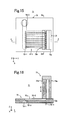
- a liquid injection apparatus in accordance with a fourth embodiment of the present invention will then be described with reference to Fig. 10 to Fig. 14.
- An injection unit 51 of this liquid injection apparatus is shown in a front view of Fig. 10, a plan view of Fig. 11, and a side view of Fig. 12.
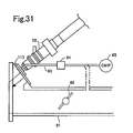
- the injection unit 51 as shown in a side view of Fig. 13 and a front view of Fig. 14, is fixed via an eject pipe 62 to a suction pipe 61 which forms an intake passage of the internal combustion engine and the liquid injection space.
- the injection unit 51 comprises a fuel injector 52 for injecting fuel and an injection unit 53 for forming liquid into fine particles using the piezoelectric/electrostrictive element.
- the fuel injector 52 for injecting fuel is a well known injector conventionally in wide use in the electrically controlled fuel injection apparatus, and herein functions as the electromagnetic open-close valve (electromagnetic open-close eject valve).
- the fuel injector 52 comprises a liquid introduction hole 52a, an liquid passage (not shown), an electromagnetic open-close needle valve (electromagnetic valve) for opening and closing the liquid passage, and a liquid eject port 52b.
- the liquid introduction hole 52a is supplied with the fuel from the liquid storage tank (not shown) by the pressurizing pump(not shown).
- This injector 52 ejects the liquid from the liquid eject port 52b when the electromagnetic open-close needle valve is opened by a valve open drive signal from the electric control device.
- the pressure of the fuel supplied to the liquid introduction hole 52a is kept at a constant value by an pressure regulator (not shown).
- the injection unit 53 for forming liquid into fine particles has the same configuration (arrangement, or composition) as those described with reference to Fig. 2 and Fig. 3.
- a plane on which the liquid injection openings 14-4a shown in Fig. 2 and Fig. 3 is formed is positioned to be orthogonal to the axial direction of the injector 52.
- the liquid fill port 14-5 shown in Fig. 2 is connected to the liquid eject port 52b of the fuel injector 52.
- this injection unit 51 is fixed to the suction pipe 61 in a manner that the main axis direction of the injection from the injection unit 53 via the eject pipe 62 crosses a line extending in a direction parallel to the axial line of the suction pipe 61 with an acute angle, and the injection unit 51 injects the atomized fuel (the fuel formed into fine particles) into the suction pipe 61.
- the liquid injection apparatus has the configuration (composition) that the injection unit 53 for forming fine particles is fixed (set) to the injector 52 which is the slightly modified conventional fuel injector, and therefore resulting in low costs and high reliability.
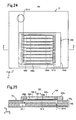
- FIG. 15 shows a plan view of the in jection unit 71
- Fig. 16 shows a sectional view of the injection unit 71 taken along line 2-2 of Fig. 15.
- This injection unit 71 comprises a flow passage forming section 72 and a pressurizing section 73.
- the flow passage forming section 72 has the same configuration (composition) as that of the flow passage forming section 14A of the injection unit 14 described above. That is, the flow passage forming section 72 comprises a liquid supply passage 72-1 inside, a plurality (herein nine) of chambers 72-2 being mutually independent, a plurality of liquid introduction holes 72-3 having each of the chambers 72-2 communicate with the liquid supply passage 72-1, a plurality of liquid ejection nozzles 72-4 having each of the chambers 72-2 communicate with an outer portion of the injection unit 71, and a liquid fill port 72-5.
- the flow passage forming section 72 is formed of zirconia ceramics, except for an upper wall (wall surface) 72a of the each chambers 72-2.
- the upper wall 72a forming the upper wall surface of the chambers 72-2 functions as a diaphragm similarly to the ceramic sheet 14f of the injection unit 14, and is made of stainless steel in this case.
- the upper wall 72a is bonded and fixed on the upper portion (surface) of the ceramic sheet portion 72b.
- the pressurizing section 73 comprises a fixing section 73a and a piezoelectric/electrostrictive element section 73b.
- the fixing section 73a is a rigid body having an inverted L sectional shape and its undersurface, being one end surface, is fixed on the top surface of the upper wall 72a of the flow passage forming section 72 in a position which is not right above the chamber 72-2.
- the fixing section 73a fixes and holds the piezoelectric/electrostrictive element section 73b at its upper portion (lower side surface of the upper portion).
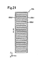
- the piezoelectric/electrostrictive element section 73b has a substantially rectangular parallelepiped shape whose sides extend in parallel with the corresponding orthogonal X, Y, and Z axes, and is a "layered piezoelectric actuator" which is formed by layering alternately a plurality of the layered piezoelectric/electrostrictive elements and a plurality of layered electrodes.
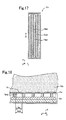
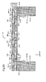
- the piezoelectric/electrostrictive element section 73b comprises a comb-tooth-like electrode 73b1, a comb-tooth-like electrode 73b2, and a plurality of layered piezoelectric/electrostrictive elements (piezoelectric/electrostrictive material) 73b3, as shown in Fig. 17 of a sectional view.
- Each of the comb-tooth-like electrodes 73b1 and 73b2 comprises a plurality of electrode fingers which extend along planes parallel to the X-Z plane with having equal intervals to each other.
- Each of the electrode fingers is connected to common electrode sections formed on planes parallel to the X-Y plane.
- the electrode fingers of the comb-tooth-like electrodes 73b1 and 73b2 are arranged alternately opposite to each other.
- Each of the layered piezoelectric/electrostrictive elements 73b3 is formed between the opposed electrode fingers.
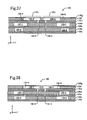
- the undersurface of the piezoelectric/electrostrictive element section 73b is bonded and fixed on the top surface of the upper wall (diaphragm) 72a by a layer comprising an adhesive (bonding layer) at the upper portion of the chamber 72-2, the upper portion being in the vicinity of the end portion of the fixing section 73a ( in the vicinity of right upper portion of the liquid ejection nozzles 72-4).
- the adhesive layer 74 is formed between the upper wall 72a of the chamber 72-2 and the undersurface of the piezoelectric/electrostrictive element section 73b, and the length (width Wa) of a side of each adhesive layer 74 extending along the X axis direction is slightly shorter than the length (width Wch) of a side of each chamber 72-2 extending along the X axis direction.
- the piezoelectric/electrostrictive element section 73b shrinks and expands in a direction (vertical direction, Z axis direction, direction parallel to the plane of the piezoelectric/electrostrictive element 73b3) indicated by arrows in Fig. 16 and Fig. 17.
- the piezoelectric/electrostrictive element section 73b is called a vertical effect type
- the capacity of the chamber 72-2 changes. This transmits the vibrations to the liquid in the chamber 72-2, and thus the liquid injected from the liquid ejection nozzle 72-4 is atomized (formed into fine particles).
- the liquid injection apparatus in accordance with the fifth embodiment has a structure that the undersurface of the piezoelectric/electrostrictive element section 73b of the pressurizing section 73 in the injection unit 71 is fixed by adhesion onto the upper wall 72a which is the diaphragm of the flow passage forming section 72, so that the upper wall 72a does not need to be ceramics that enables the piezoelectric/electrostrictive element section 73b to be integrated by burning. Therefore, the diaphragm 72a can be formed of a material, such as a metal (stainless steel in this example), that is appropriate in terms of tenacity for forming the liquid to be injected into fine particles by vibrations.
- the material forming the piezoelectric/electrostrictive element section 73b does not permeate (invade) into the upper wall 72a when burnt.
- the material forming the piezoelectric/electrostrictive element section 73b does not deteriorate characteristics such as tenacity of the upper wall 72a.
- the deforming force can also be made large by enlarging the piezoelectric/electrostrictive element section 73b in a vertical direction (Z axis direction).
- the upper wall 72a can be deformed as much as desired and the capacity variation ⁇ V of the chamber 72-2 can be large, even if the rigidity of the upper wall 72a becomes larger when the length of the major axis of the chamber 72-2 (length in the Y axis direction) and/or the length of the minor axis (length in the X axis direction) are/is reduced.
- This makes it possible to reduce the area of an injection surface of the injection unit 71 on which the eject ports of the liquid ejection nozzle 72-4 is formed (i.e. the area of the undersurface (X-Y plane) of the flow passage forming section 72).
- the injection surface from which the liquid (gasoline) is injected can be placed in a proper (desired) position of an introduction system (intake system) of the internal combustion engine, and high-density liquid droplets of gasoline atomized can be injected at a proper (desired) region of the introduction system of the engine.
- the force for deforming generated by the piezoelectric/electrostrictive element section 73b can be efficiently transmitted to the upper wall 72a functioning as the diaphragm of each chamber 72-2, since the length (width Wa) of the side in the X axis direction of each adhesive layer 74 is slightly shorter than the length (width Wch) of the side in the X axis direction of each chamber 72-2. Therefore, the upper wall 72a can certainly be deformed even with a little force, so that the capacity of each chamber 72-2 is certainly changed, thereby the atomization of the injected liquid can be certainly achieved.
- FIG. 19 shows a plan view of the injection unit 81
- Fig. 20 shows a sectional view of the injection unit 81 taken along line 4-4 of Fig. 19.
- the injection unit 81 comprises a flow passage forming section identical to the flow passage forming section 72 of the injection unit 71, and a pressurizing section 83.
- the pressurizing section 83 comprises a fixing section 83a identical to the fixing section 73a of the injection unit 71 and a piezoelectric/electrostrictive element section 83b. This means that the injection unit 81 is different from the injection unit 71 only in that the piezoelectric/electrostrictive element section 73b of the injection unit 71 is replaced with the piezoelectric/electrostrictive element section 83b. Therefore, hereinafter, the piezoelectric/electrostrictive element section 83b will be described in detail.
- the piezoelectric/electrostrictive element section 83b is a "multilayered piezoactuator of a horizontal effect type" which is formed by layering alternately a plurality of the layered piezoelectric/electrostrictive elements and a plurality of layered electrodes.
- the piezoelectric/electrostrictive element section 83b comprises a comb-tooth-like electrode 83b1, a comb-tooth-like electrode 83b2, and a plurality of layered piezoelectric/electrostrictive elements 83b3, as shown in Fig. 21 of a sectional view.
- Each of the comb-tooth-like electrodes 83b1 and 83b2 comprises a plurality of electrode fingers which extend along planes parallel to the X-Y plane with having equal intervals to each other. These fingers extend from common electrodes section formed on planes parallel to the X-Z plane.
- the electrode fingers of the comb-tooth-like electrodes 83b1 and 83b2 are arranged alternately opposite to each other.
- Each of the layered piezoelectric/electrostrictive elements 83b3 is formed between the opposed electrode fingers.
- the piezoelectric/electrostrictive element section 83b shrinks and expands in a direction (vertical direction, Z axis direction) indicated by arrows in Fig. 20 and Fig. 21, that is, in a direction orthogonal to the plane of the piezoelectric/electrostrictive element section 83b.
- the capacity of the chamber 72-2 changes. This transmits the vibrations to the liquid in the chamber 72-2, and thus the liquid injected from the liquid ejection nozzle 72-4 is atomized (formed into fine particles).
- the same effects can be obtained as that of the liquid injection apparatus of the fifth embodiment. That is, the undersurface of the piezoelectric/electrostrictive element section 83b of the pressurizing section 83 in the injection unit 81 is fixed by adhesion onto the upper wall 72a, so that the upper wall 72a can be formed of a material appropriate in terms of tenacity for forming the liquid to be injected into fine particles by vibrations.
- the piezoelectric/electrostrictive element section 83b is the "multilayered piezoactuator of a horizontal effect type"
- the force (deforming force, pressurizing force) to deform the upper wall 72a can be relatively large and the upper wall 72a can be greatly deformed, even if the voltage given across the comb-tooth-like electrodes 83b1 and 83b2 is relatively low, thereby power consumption by the liquid injection apparatus can be reduced.
- the deforming force can also be made large by enlarging the piezoelectric/electrostrictive element section 83b in a vertical direction (Z axis direction).
- the upper wall 72a can be deformed as much as desired and the capacity variation ⁇ V of the chamber 72-2 can be large, even if the rigidity of the upper wall 72a becomes larger when the length of the major axis of the chamber 72-2 (length in the Y axis direction) and/or the length of the minor axis (length in the X axis direction) are/is reduced. Therefore, for the same reason as that of the fifth embodiment, the area of the injection surface of the injection unit 81 can be reduced.
- FIG. 22 shows a plan view of the injection unit 91
- Fig. 23 shows a sectional view of the injection unit 91 taken along line 5-5 of Fig. 22.
- This injection unit 91 comprises a flow passage forming section identical to the flow passage forming section 14A of the injection unit 14, and a pressurizing section 92.
- the pressurizing section 92 is a piezoelectric/electrostrictive element section, and has a substantially rectangular parallelepiped shape whose sides extend in parallel with the corresponding orthogonal X, Y, and Z axes.
- the pressurizing section 92 is a "multilayered piezoactuator" which is formed by layering alternately a plurality of the layered piezoelectric/electrostrictive elements and a plurality of layered electrodes. That is, the pressurizing section 92 has the same structure as the one shown in Fig. 21 in which length in the Z axis direction of the piezoelectric/electrostrictive element section 83b is shortened and the length in the Y axis direction is elongated.
- the length in the Y axis direction of the pressurizing section 92 is much the same as or slightly shorter than the length in the Y axis direction of the chamber 14-2, and the length in the X axis direction is slightly longer than the distance between one chamber 14-2 positioned at an end portion in the X positive direction and one chamber 14-2 positioned at an end portion in the X negative direction.
- the undersurface of the pressurizing section 92 is integrally joined, at upper portion of the chamber 14-2, by burning onto the top surface of the ceramic sheet 14f serving as the upper wall of the chamber.
- the pressurizing section 92 operates in the same manner as the piezoelectric/electrostrictive element 14g of the injection unit 14 to deform the ceramic sheet 14f and changes the capacity of the chamber 14-2 by ⁇ V. This transmits the vibrations to the liquid in the chamber 14-2, and thus the liquid in jected from the liquid ejection nozzle 14-4 is atomized (formed into fine particles).
- the pressurizing section 92 is the multilayered piezoactuator, much displacement ( a large amount of change in capacity of the chamber) can be obtained with a low voltage as compared with the injection unit 14, thereby resulting in the lower power consumption of the liquid injection apparatus.
- the ceramic sheet 14f may be replaced with the upper wall 72a in the fifth embodiment, and the undersurface of the pressurizing section 92 may be joined by adhesion onto the top surface of the upper wall 72a.
- the upper wall 72a can be formed of a material such as a metal (stainless steel in this example) that is appropriate in terms of tenacity for forming the liquid into to be injected into fine particles by vibrations.
- the adhesive layer is provided only within the immediate upper portion of the chamber 14-2.
- FIG. 24 shows a plan view of the injection unit 101
- Fig. 25 shows a sectional view of the injection unit 101 taken along line 6-6 of Fig. 24.
- This injection unit 101 comprises a flow passage forming section identical to the flow passage forming section 72 of the injection unit 71, and a pressurizing section 102.
- the pressurizing section 102 comprises a fixing section 102a, a plurality of piezoelectric/electrostrictive element sections 102b, a piezoelectric/electrostrictive element holding section 102c, spacer section 102d and a cover section 102e.
- This injection unit 101 has a substantially rectangular parallelepiped shape whose sides extend in parallel with the corresponding orthogonal X, Y, and Z axes as a whole.
- the fixing section 102a is a rectangular frame of which outer circumferential shape and inner circumferential shape have sides extending along X axis and Y axis in a plan view, and its undersurface is bonded to the upper surface of the upper wall 72a.
- the length of one side along Y axis of the inner circumferential shape of the fixing section 102a is substantially equal to the length in the Y axis direction of the chamber 72-2 of the flow passage forming section 72, and the other side of length along X axis direction is slightly longer than the distance between one chamber 72-2 positioned at an end portion in the X positive direction and one chamber 72-2 positioned at an end portion in the X negative direction.
- the piezoelectric/electrostrictive element sections 102b is a thin plate (laminate) which has a rectangular shape in a plan view. Its width (length in the X axis direction) of the rectangular is almost the same as or slightly shorter than the width (length in the X axis direction) of the chamber 72-2, and its length (length in the Y axis direction) of the rectangular is slightly shorter than the length (length in the Y axis direction) of the chamber 72-2.
- the number of the piezoelectric/electrostrictive element sections 102b is the same as that of the chambers 72-2.
- the piezoelectric/electrostrictive element sections 102b are disposed in a manner that each of them overlaps each of the chambers 72-2 at a central portion in the Y axis direction of each chamber 72-2 and above each of the chamber (i.e., the piezoelectric/electrostrictive element sections 102b are disposed in such a manner that each of their major axes and each of the major axes of the chambers are substantially on the same line, in a plan view).
- the undersurface of the piezoelectric/electrostrictive element section 102b is bonded to the upper surface of the upper wall 72a of the flow passage forming section 72.
- the piezoelectric/electrostrictive element holding section 102c is a ceramic plate (zirconia board) having a rectangular shape in a plan view, and its outer circumferential shape is substantially the same as the inner circumferential shape of the fixing section 102a.
- This piezoelectric/electrostrictive element holding section 102c integrally joins, at its lower surface, the piezoelectric/electrostrictive element section 102b by burning.
- the piezoelectric/electrostrictive element holding section 102c does not need to be a rigid body, but has rigidity higher than the rigidity of the upper wall 72a of the flow passage forming section 72.
- the spacer section 102d is a rectangular frame of which outer circumferential shape and inner circumferential shape have sides extending along X axis and Y axis in a plan view.
- the outer circumferential shape of the spacer section 102d has the same shape as the inner circumferential shape of the fixing section 102a.
- the inner circumferential shape of the spacer 102d is larger than the shape of an outline of the piezoelectric/electrostrictive element section 102b in a plan view so that both shapes do not overlap.
- the spacer section 102d is disposed above the piezoelectric/electrostrictive element holding section 102c, and inside the fixing section 102a.
- the cover section 102e is a board having high rigidity of which outer circumferential shape is the same as the inner circumferential shape of the fixing section 102a in a plan view, and is positioned above the spacer 102d and inside the fixing section 102a.
- an air gap section 102-1 is formed which is defined by the piezoelectric/electrostrictive element holding section 102c, the spacer section 102d, and the cover section 102e.
- the ceramic plate which is the piezoelectric/electrostrictive element holding section 102c, is fixed immovably to the flow passage forming section 72 with a certain distance from the upper wall 72a of the chamber 72-2 when the upper wall 72a of the chamber 72-2 is not deformed.
- the piezoelectric/electrostrictive element section 102b is hermetically stuck and disposed between the ceramic plate 102c and the upper wall 72a.
- the cover section 102e is provided with a plurality of through-holes 102-2 so that air comes in and out of the air gap 102-1 when the capacity of the air gap 102-1 varies.
- the fixing section 102a, the piezoelectric/electrostrictive element holding section 102c, the spacer section 102d and the cover section 102e are formed of ceramics, and integrated by burning.
- the piezoelectric/electrostrictive element section 102b integrally joined by burning to the piezoelectric/electrostrictive element holding section 102c of the ceramic plate repeatedly presses the upper wall 72a of the chamber that functions as a diaphragm by means of piezoelectric/electrostrictive element section 102b. This changes the capacity of the chamber 72-2 to form the liquid to be injected into fine particles.
- parts that are substantially relating to the vibrations caused by the piezoelectric/electrostrictive element section 102b include the chamber 72-2, the upper wall 72a serving as the diaphragm, the piezoelectric/electrostrictive element section 102b and the piezoelectric/electrostrictive element holding section 102c, and the rigidity of the piezoelectric/electrostrictive element holding section 102c is higher than the rigidity of the upper wall 72a, the resonance frequency of the parts comprised of these parts relating to the vibrations is increased and become larger than the resonance frequency of the parts relating to the vibrations in the injection unit 14.
- the diaphragm 72a (upper wall surface to be deformed of the chamber 72-2) functioning as the diaphragm is vibrated at the frequency lower than the resonance frequency of the parts relating to the vibrations of the diaphragm 72a
- the diaphragm 72a is deformed only from a nodal line (line of intersection) of (between) the diaphragm 72a and other walls of the chamber 72-2.
- the diaphragm 72a is deformed from upper corner of the chamber 72-2 located at Z axis positive direction. That is, the diaphragm 72a is deformed in such a manner that it has a single abdomen.
- the vibrations necessary to inject the liquid in the chamber 72-2 as fine particles having a desired particle diameter can certainly be added to the liquid.
- the diaphragm 72a is vibrated at a frequency higher than the resonance frequency of the parts substantially relating to the vibrations, the diaphragm 72a is deformed in such a manner that it has a plurality of wave fronts, and it will be difficult to properly add to the liquid the vibrations for forming the injected liquid into the fine particles having a desired particle diameter.
- the resonance frequency of the parts substantially relating to the vibrations caused by the piezoelectric/electrostrictive element section 102b is raised, it is possible to certainly form the liquid into fine particles even if the upper wall 72a of the chamber 72-2 is vibrated at a higher frequency, thereby the particle diameter of the injected liquid can be made smaller.
- the pressure (ejecting pressure) generated by the pressurizing pump 11 serving as the pressurizing means is heightened to increase the injection amount per unit time, the liquid can certainly be atomized by vibrating the upper wall 72a of the chamber 72-2 at the higher frequency up to the heightened frequency mentioned above. Therefore, it becomes possible to supply a large amount of the liquid which is atomized, according to the present embodiment.
- the cover section 102e is provided, however, this cover section 102e may be omitted.
- the upper wall 72a and the piezoelectric/electrostrictive element section 102b are bonded. Therefore, unlike the injection unit that joins these by burning, the material forming the piezoelectric/electrostrictive element section 102b does not deteriorate characteristics such as tenacity of the upper wall 72a.
- the option of the material for the upper wall 72a is broadened (the material for the upper wall 72a is chosen from more variety of materials).
- the piezoelectric/electrostrictive element section 102b may be the multilayered piezoactuator.
- a liquid injection apparatus in accordance with a ninth embodiment of the present invention will then be described.
- This liquid injection apparatus adopts an injection unit 14' which is obtained by modifying the injection unit 14, in place of the injection unit 14 described above. Therefore, hereinafter, the difference from the injection unit 14 will be mainly described with reference to Fig. 26 to Fig. 28.
- the liquid ejection nozzle 14-4 comprises the liquid injection opening 14-4a and the hollow cylindrical communicating holes 14-4b to 14-4d that are formed in ceramic sheets 14b to 14d whose sizes (diameters) become larger in order from the liquid injection opening 14-4a to the chamber 14-2, respectively.
- the shape of the liquid injection opening 14-4a is circular.
- the liquid ejection nozzle 14-4' comprises (or is formed of) the hollow cylindrical communicating hole 14-4d provided in the ceramic sheet 14d, the hollow cylindrical communicating hole 14-4c provided in the ceramic sheet 14c that is coaxial with the communicating hole 14-4d and has a diameter smaller than that of the communicating hole 14-4d, a hollow columnar communicating hole 14-4b' that is coaxial with the communicating hole 14-4c and is provided in the ceramic sheet 14b, and a plurality (in this example, three rows times six lines equals 18 in total) of hollow columnar communicating holes 14-4a' ... 14-4a', each communicating with the communicating hole 14-4b'.
- the communicating hole 14-4b' has an oval section as shown in Fig. 27.
- Each cavity (chamber) 14-2 communicates with a plurality of liquid injection openings 14-4a'.
- the length of the minor axis of the communicating hole 14-4b' is equal to the diameter of the communicating hole 14-4c.
- the sectional shape of the communicating hole 14-4a' is elliptic,whose length of the major axis is LL and length of the minor axis is LS.
- the communicating hole 14-4a' having the elliptic sectional shape described above can be formed by an electron beam method, a punching method, a laser processing method or the like.
- the laser processing method is preferable as the focal point is easily adjusted and the targeted elliptic shape is certainly obtained.
- the shape of the liquid injection opening i.e. sectional shape of the communicating hole 14-4a'
- the average diameter of the injected liquid droplets (particles) becomes smaller, compared with the case where the shape of the liquid injection opening is a circular shape having about the same sectional area as the area of the elliptic shape.
- the shape of the liquid injection opening is made elliptic to have the same opening area as in the case where the shape of the liquid injection opening is a circle having the predetermined diameter D
- the minor axis LS of the ellipse is shorter than the diameter D of the circle, and therefore, the minimum diameter of the constriction of the ejected liquid caused by the vibrations added to the liquid in the chamber becomes smaller than that in the case where the shape of the liquid injection opening is circular.
- liquid has properties of becoming spherical by surface tension in space. Therefore, liquid ejected (injected) from the elliptic liquid injection opening separates more easily at (from) the minimum diameter portion (i.e. the constriction portion) that is smaller than the minimum diameter in the case where the shape of the liquid injection opening is circular, and becomes spherical fine particles having a diameter smaller than a diameter of particles obtained in the case where the shape of the liquid injection opening is circular.
- the ejected liquid volume i.e. injection amount per unit time
- the particle diameter of the ejected liquid is kept the same as or smaller than the particle diameter in the case where the shape of the liquid injection opening is circular.
- the minor axis length LS of the elliptic shape of the liquid injection opening can be almost equal to the diameter D. Accordingly, because the major length LL of the elliptic shape can be larger than the diameter D of the circular shape, the area of the liquid injection opening can be larger, and therefore, the volume of the injected liquid (eject flow volume) can be increased.
- a ratio (LL/LS) of the major axis length LL to the minor axis length LS when the liquid injection opening is elliptic is preferably 1.5 or more.
- the liquid injection opening in the unit used in this experiment has the elliptic shape whose major axis is 0.007 mm and whose minor axis is 0.005 mm.
- the shape of the liquid injection opening 14-4a' (the shape of the liquid injection opening of the liquid ejection nozzle 72-4) as viewed from the axial direction of the liquid ejection nozzle does not need to be elliptic, and may have an oval shape (or an elongated circle) having a major axis and a minor axis as shown in Fig. 29, and also may be rectangular having a major axis (a longer side) and a minor axis (a shorter side) as shown in Fig. 30.
- the area of the oval or the area of the rectangle can be made equal to the area of the circle while the minor axis of the oval or the short side (minor axis) of the rectangle is made shorter than the diameter of the circle. Therefore, by making the shape of the liquid injection opening 14-4a oval or rectangular, the minimum diameter of the constriction of the ejected liquid caused by the vibrations added to the liquid in the chamber 14-2 becomes smaller compared with the case where the shape of the liquid injection opening 14-4a is circular. Thus, it becomes easier to form the liquid into finer particles since the liquid separates at (from) such a constriction portion having the smaller minimum diameter.
- the shape of the liquid injection opening 14-4a (or the liquid injection opening of the liquid ejection nozzle 72-4) the shape having a minor axis and a major axis, such as the oval, an elongated circle, or the rectangle, the capacity variation ⁇ V of the chamber 14-2 (or the chamber 72-2) for forming the injected liquid into fine particles can be decreased, and thus, the displacement amount of the ceramic sheet 14f (or the upper wall 72a) serving as the diaphragm, the displacement being caused by the piezoelectric/electrostrictive element 14g (or the pressurizing sections 73, 83, 92 and 102), can be decreased.
- the liquid can be atomized (can be formed into fine particles as desired) even if the voltage of the drive voltage signal applied to the piezoelectric/electrostrictive element 14g (or the pressurizing sections 73, 83, 92 and 102) is low, and therefore the power consumption of the injection unit can be reduced.
- This liquid injection apparatus is fixed to the suction pipe 61 that is the intake passage of the internal combustion engine and forms the liquid injection space as shown in Fig. 31.
- This liquid injection apparatus comprises the fuel injector 52 for injecting fuel as described with reference to Fig. 10, an air pipe 63 forming an air passage, an electromagnetic open-close valve 64 interposed in the air pipe 63, a compressor 65, and an injection unit 110 for forming liquid into fine particles that uses the piezoelectric/electrostrictive element.
- the injector 52 comprises a needle valve for opening an internal fuel passage when an injector driving signal is turned "ON" (high level).
- This fuel passage is supplied with the fuel from the liquid storage tank (not shown). The pressure of the fuel supplied to the fuel passage is adjusted by the pressure regulator (not shown).
- the injection unit 110 not only injects atomized liquid (liquid fuel) into the liquid injection space 21, but also injects gas (air) into the liquid injection space 21.
- the liquid injection direction (main axis of the liquid injection direction) and the gas injection direction (main axis of the gas injection direction) are parallel to each other.
- this injection unit 110 has a substantially rectangular parallelepiped shape whose sides extend in parallel with the corresponding orthogonal X, Y, and Z axes.
- the injection unit 110 comprises a flow passage forming section made of a plurality of ceramic sheets 110a to 110e layered in order and stuck by pressure, and a pressurizing section made of piezoelectric/electrostrictive elements 110f fixed onto the exterior surface of the ceramic sheet 110f, as in Fig. 32 showing a plan view, and as in Fig. 33 showing a sectional view of the injection unit 110 taken along line 7-7 of Fig. 32.
- This injection unit 110 also comprises therein, as a liquid supply system, a liquid supply passage 110-1, a plurality of chambers 110-2 (herein, four lines, each of the lines including 9 chambers , resulting in 36 chambers in total) being mutually independent, a plurality of liquid introduction holes 110-3 having each of the chambers 110-2 communicate with the liquid supply passage 110-1, a plurality of liquid ejection nozzles 110-4 having each one end substantially exposed to the liquid injection space to have each of the chambers 110-2 communicate with the outer portion of the injection unit 110, and a liquid fill port 110-5 to which the liquid eject port of the injector 52 for injecting fuel is coupled.
- the liquid fill port 110-5 is provided at only one place in the central part in the Y axis direction.
- the liquid supply passage 110-1 communicating with the liquid fill port 110-5 extends to both sides in the Y axis direction and then branches out into four passages extending in the X axis direction.
- Each branch line extending in the X axis direction of the liquid supply passage 110-1 communicates with the nine chambers 110-2 via the nine liquid introduction holes 110-3.
- the capacity of the chambers 110-2 is varied by the operation of the piezoelectric/electrostrictive elements 110f.
- This injection unit 110 comprises therein, as a gas supply system, a pair of gas supply passages 110-6 provided at each of end portions in Y axis direction, a plurality of chambers 110-7 being mutually independent (herein, two lines are provided, one line having nine chambers, resulting in 18 in total), a plurality of gas introduction holes 110-8 having each of the chambers 110-7 communicate with each of the gas supply passages 110-6, a plurality of air flowing nozzles 110-9 having each one end substantially exposed to the liquid injection space 21 to have each of the chambers 110-7 communicate with the outer portion of the injection unit 110, and a pair of gas fill ports 110-10 to which one end of the air pipe 63 is coupled and each of which communicates with each of the pair of gas supply passages 110-6.
- the gas supply passage 110-6 has a structure similar to that of the liquid supply passage 110-1.
- the gas supply passage 110-6 is a space defined by side wall surfaces in the ceramic sheet 110b forming a cutout having an elongated circular shape whose major and minor axes extend in parallel with X and Y axes directions, respectively, an top surface (upper surface) of the ceramic sheet 110a, and an undersurface (lower surface) of the ceramic sheet 110c.
- the gas supply passage 110-6 communicates with the compressor 65 via the gas fill port 110-10 formed in ceramic sheets 110c to 110e and via the air pipe 63, and is supplied with the pressurized (compressed) air to be injected when the electromagnetic open-close valve 64 is opened.
- Each of the plurality of chambers 110-7 is a space having a longer axis and a shorter axis similar to the chambers 110-2, the space being defined by the side wall surface of a cutout space, formed in the ceramic sheet 110d, of which shape is an elongated circle whose major and minor axes are in parallel with Y axis direction and an X axis direction, respectively, an top surface (upper surface) of the ceramic sheet 110c, and an undersurface (lower surface) of the ceramic sheet 110e.
- One end of each of the chambers 110-7 extends up to an upper portion of the gas supply passage 110-6. and each of the chambers 110-7 communicate, at the one end, with the gas supply passage 110-6 by means of the hollow cylindrical gas introduction hole 110-8 which is formed in the ceramic sheet 110c.
- Each of the air nozzles 110-9 is a hollow cylindrical through-hole which is provided in the ceramic sheets 110a to 110c and has an axial line in the Z axis direction, and has a gas injection opening 110-9a at one end substantially exposed to the liquid injection space 21, thereby having the chamber 110-7 communicates with the liquid injection space.
- the injection unit 110 further comprises a pair of air current direction control wall sections 110-11 which is in the lower portion (Z axis negative direction) of the ceramic sheet 110a and at both ends in Y axis direction.
- Each of air current direction control wall sections 110-11 has a rectangular parallelepiped shape whose sides extends in parallel with the X, Y and Z axes directions, respectively and its top surface (surface parallel to the X-Y plane) is bonded to the undersurface of the ceramic sheet 110a.
- a pair of wall surfaces (air current direction control wall surface) 110-11a,110-11a, parallel to the X-Z plane, of the air current direction control walls 110-11 are opposed to each other.
- Each of the air current direction control wall surfaces 110-11a, 110-11a is built at the position outside in the Y axis direction apart from each of the gas injection openings 110-9a and 110-9a with a some distance, as in Fig. 35 showing enlarged view.
- the gas injection openings 110-9a and 110-9a are positioned at both ends in the Y direction of the injection unit 110.
- the injection unit 110 comprises nine liquid injection openings and nine gas injection openings per each line extending in the X axis direction on the undersurface (lower plane) of the injection unit 110.
- a line of gas injection openings, four lines of liquid injection openings and a line of gas injection openings are positioned in order from the end portion of the Y axis negative direction side to the Y axis positive direction side.
- an injector driving signal a piezoelectric/electrostrictive element driving signal and an electromagnetic open-close valve driving signal, shown in Fig. 34, are provided to the injector 52, each of the piezoelectric/electrostrictive elements 110f and the electromagnetic open-close valve 64, respectively, from the electric control device (not shown).
- the electric control device inputs engine operation states such as an engine rotation speed N and suction pipe pressure P to perform a necessary calculation, and outputs each of the driving signals mentioned above.
- the electric control device not only determines the injector driving signal (length of a high level signal) on the basis of the engine operation states such as the engine rotation speed N and the suction pipe pressure P, but also determines the timing (the timing t102 in Fig. 34) to output the injector driving signal.
- the electric control device starts giving (sending) the piezoelectric/electrostrictive element driving signal having a frequency f across the electrodes of the piezoelectric/electrostrictive elements 110f at the timing t101 prior to the timing t102 by predetermined time period, and changes the electromagnetic open-close valve driving signal from "OFF" to "ON" (high level).
- the electric control device then changes the injector driving signal from "OFF” to "ON” (high level) at the timing t102 slightly after the timing t101.
- the needle valve (not shown) of the injector 52 is moved, fuel starts being ejected and supplied to the liquid supply passage 110-1 via the liquid fill port 110-5 of the injection unit 110, and then starts flowing into the chamber 110-2 via the liquid introduction hole 110-3.
- the pressure of the fuel in the chamber 110-2 rises to an adequate pressure, the fuel is pressed out (injected) towards the liquid injection space in the suction pipe 61 from the liquid injection opening of the liquid ejection nozzle 110-4.
- the electric control device then changes the injector driving signal from "ON” to "OFF” (low level) at the timing t103.
- the electric control device stops giving the piezoelectric/electrostrictive element driving signal and changes the electromagnetic open-close valve driving signal for the electromagnetic open-close valve 64 from “ON” to "OFF” (low level) at the timing t104 which is slightly after the timing t103 to stop the air injection (gas injection) from the air flowing nozzles 110-9.
- the electric control device performs similar fuel injection control repeatedly as indicated from the timing t105 to t108 in Fig. 34.
- air injection from the gas injection opening is started at the timing t101 prior to the timing t102 when fuel injection is started, and the air injection is continued until the timing t104 later than the timing t103 when the fuel injection is stopped.
- Fig. 35 showing a partially enlarged view of the vicinities of the gas injection opening of the injection unit 110, it is possible to reduce the amount of liquid film EM remaining and sticking (adhering) on the wall surface (undersurface of the ceramic sheet 110a) in the vicinity of the liquid injection opening 110-4a at the timing of stopping the fuel injection, and moreover, the liquid film EM can be removed before next fuel injection since the liquid film EM can be atomized (removed) by the air current. As a result, it is possible to certainly form the fuel into fine particles when the fuel injection is started, and to avoid liquid droplets having a large particle diameter due to the liquid film EM. Thus, it is possible to reduce the amount of the undesirable exhaust gas from the internal combustion engine.
- the air current direction control wall surfaces 110-11a of the air current direction control wall sections 110-11 are provided, and air is injected from a position near the air current direction control wall surfaces 110-11a, so that the main components (current) of the air current can be brought into about the same direction (in this case, the air current proceeds mainly along Z axis negative direction). Therefore, it is possible to certainly transport the injected liquid droplets to the predetermined position (the desired region).
- FIG. 36 shows a plan view of the injection unit 130
- Fig. 37 to Fig. 39 show sectional views of the injection unit 130 taken along line 8-8, line 9-9 and line 10-10 of Fig. 36, respectively.
- This injection unit 130 injects air together with fuel, similarly to the injection unit 110.
- the injection unit 130 is different from the injection unit 110 in that the liquid injection opening and the gas injection opening are arranged alternately in one line (line along the X axis) on the undersurface of the injection unit 130.
- the injection unit 130 has a substantially rectangular parallelepiped shape whose sides extend in parallel with orthogonal X, Y and Z axes, and comprises a flow passage forming section made of a plurality of ceramic sheets 130a to 130g layered and stuck by pressure in order, and a pressurizing section made of piezoelectric/electrostrictive elements 130h fixed onto the exterior surface (plane parallel to the X-Y plane in the Z axis direction) of the ceramic sheet 130g.
- This injection unit 130 comprises therein, as a liquid supply system, a liquid supply passage 130-1, a plurality of liquid pressurizing chambers 130-2 (herein, two lines, each of the lines including five, resulting in 10 in total) being mutually independent, a plurality of liquid introduction holes 130-3 having each of the chambers 130-2 communicate with the liquid supply passage 130-1, a plurality of liquid ejection nozzles 130-4 having each one end substantially exposed to the liquid injection space to have each of the chambers 130-2 communicate with the outer portion of the injection unit 130, and a liquid fill port 130-5 to which the liquid eject port of the injector 52 for injecting fuel is coupled.
- the liquid supply passage 130-1 is a space defined by side walls forming hollow space in the ceramic sheet 130d, an undersurface of the ceramic sheet 130e, and an top surface of the ceramic sheet 130c.
- the chamber 130-2 is a space defined 130f, an undersurface of the ceramic sheet 130g and an top surface of the ceramic sheet 130e.
- the liquid introduction hole 130-3 is a hollow cylindrical space to penetrate the ceramic sheet 130e to have the liquid supply passage 130-1 communicate with the chambers 130-2.
- the liquid ejection nozzle 130-4 is a hollow cylindrical through-hole formed in the ceramic sheets 130a to 130e to have the chambers 130-2 communicate with the outside of the injection unit 130 via the liquid injection opening formed in the sheet 130a.
- only one liquid fill port 130-5 is provided at the central portion in the Y axis direction and in the vicinity of end portion of X axis negative direction.
- the liquid supply passage 130-1 communicating with the liquid fill port 130-5 extends to both outer directions along Y axis, and further extends in the X axis positive direction from the portion extending in the outer directions to form a pair (two lines) of liquid supply passages 130-1.
- Each of the five liquid pressurizing chambers 130-2 communicates with one line of the liquid supply passages 130-1 via the five liquid introduction holes 130-3. Further, the capacity of the chamber 130-2 is varied by the operation of the piezoelectric/electrostrictive elements 130h.
- This injection unit 130 comprises therein, as a gas supply system, a gas supply passage 130-6, a plurality of gas chambers 130-7 being mutually independent (herein, two lines are provided, one line having four chambers, resulting in eight in total), a plurality of gas introduction holes 130-8 having each of the chambers 130-7 communicate with each of the gas supply passages 130-6, a plurality of air nozzles (gas ejection nozzles) 130-9 having each one end substantially exposed to the liquid injection space to have each of the chambers 130-7 communicate with the outer portion of the injection unit 130, and a gas fill port 130-10 to which one end of the air pipe 63 shown in Fig. 31 is coupled and which communicates with the gas supply passage 130-6.
- the gas supply passage 130-6 is a space defined by side walls forming hollow space in the ceramic sheet 130b, an undersurface of the ceramic sheet 130c, and an top surface of the ceramic sheet 130a.
- the chamber 130-7 is a space by side walls of a hollow formed in the ceramic sheet 130f, an undersurface of the ceramic sheet 130g, and an top surface of the ceramic sheet 130e.
- the gas introduction hole 130-8 is a hollow cylindrical space to penetrate the ceramic sheets 130c to 130e for having the gas supply passage 130-6 communicate with the chambers 130-7.
- the air nozzle 130-9 is a hollow cylindrical through-hole formed in the ceramic sheets 130a to 130e and whose axial line extends in Z axis direction to have the chambers 130-7 communicate with the outside of the injection unit 130 via the gas injection opening formed in the sheet 130a.
- only one gas fill port 130-10 is provided at the central portion in the Y axis direction and in the vicinity of end portion of X axis positive direction.
- the gas supply passage 130-6 communicating with gas fill port 130-10 extends to both outer directions along Y axis, and further extends in the X axis negative direction from the portion extending in the outer directions to form a pair (two lines) of gas supply passages.
- Each of the four gas chambers 130-7 communicates with one line of the gas supply passages 130-6 via the four gas introduction holes 130-8.
- the injector driving signal, the piezoelectric/electrostrictive element driving signal and an electromagnetic open-close valve driving signal as shown in Fig. 34 are provided to the injector 52, each of the piezoelectric/electrostrictive elements 130h and the electromagnetic open-close valve 64, respectively, from the electric control device not shown.
- liquid droplets atomized by the capacity change of the chamber 130-2 and injected are transported on and by the air current to the predetermined position, because the fuel injection and the air injection are performed synchronously. This prevents the atomized liquid droplets from drifting (remaining) at the same position. Thus, it is possible to prevent the particle diameter of the liquid droplets from becoming larger. Accordingly, the amount of fuel sticking or adhering onto the wall surface of the suction pipe 61 decreases, thereby fuel consumption of the internal combustion engine can be improved and the amount of the undesirable exhaust gas from the internal combustion engine can be reduced more effectively.
- the air current is being generated before and after fuel injection, it is possible to reduce the amount of liquid film remaining and sticking (adhering) onto the wall surface (undersurface of the ceramic sheet 130a) in the vicinity of the liquid injection opening, and it is also possible to atomize and remove the liquid film by the air current before next fuel injection.
- the fuel can certainly be atomized when the fuel injection is started, and it is possible to avoid liquid droplets having a large particle diameter due to the liquid film.
- the liquid injection openings of the nozzle 130-4 and the gas injection openings of the nozzle 130-9 are arranged alternately, the injected liquid droplets can easily be transported by the air current, thereby it is possible to reduce the amount of recombining of the injected liquid. It is also possible to remove the liquid film in the vicinity of the liquid injection opening by the air current easily (because of the alternate arrangement of the liquid injection openings and the gas injection openings).
- the injection speed of air is designed to be higher than the injection speed of fuel. This can be accomplished by, for example, adjusting the compressive force of the air compressor. The reason why this is preferable is that, the injected air current can not overcome the air current generated by the injected liquid droplets, if the injection speed of air is lower than the injection speed of fuel, which makes it impossible to transport the liquid droplets to the desired place (region).
- the configuration may be such that, as indicated with dashed lines in Fig. 31, the other end of the air pipe 63 is made to communicate with the suction pipe 61 at upstream of a throttle valve 66 of the internal combustion engine, and air is injected from the injection units 110 and 130 by the differential pressure between upstream and downstream of the throttle valve 66.
- the electromagnetic open-close valve 64 may be omitted.
- the other end of the air pipe 63 is opened to the atmosphere so that the air is injected by the differential pressure between atmosphere pressure and negative pressure downstream of the throttle valve.
- the structure (air assist structure) of the injection units 110 and 130 described in the tenth embodiment and the eleventh embodiment is applicable not only to what is called a pressurizing method, in which the liquid (fuel) is pressurized by the pressurizing means such as the pressurizing pump 11 to be injected, but also to, for example, a liquid injection apparatus utilizing what is called "differential pressure control pipe method" as shown in Japanese Patent Application Laid-open No. 2000-15081, or to an ink jet type apparatus that generates pressure for injecting fuel only by the capacity change (displacement) of the chambers caused by the operation of the piezoelectric/electrostrictive element.
- liquid injection apparatus in accordance with each of the embodiments of the present invention, it is possible to stably inject liquid (gasoline) uniformly atomized, regardless of environment surrounding the liquid injection apparatus (e.g. the operation state of the engine). Further, according to the embodiments described above, it is possible to inject fuel with maintaining a favorable atomization state as required, regardless of the air flow velocity in the suction pipe (intake pipe), whereas, in conventional carburetors, the flow volume of fuel (liquid) is determined in accordance with air flow velocity in the space inside the suction pipe that is corresponding to the liquid droplet eject space, and the degree of atomization is changed depending upon the air flow velocity.
- liquid injection apparatus in accordance with the present invention does not require a compressor for supplying assist air, thereby making the apparatus inexpensive, unlike a conventional apparatuses that requires the compressor to supply assist air to a nozzle section of a injector for prompting atomization of the fuel.
- the liquid to be injected be petroleum carbon hydride such as gasoline or kerosene, or synthetic carbon hydride.
- the density of the liquid to be injected by the present liquid injection apparatus be 1 g/cm 3 or less, and its viscosity be from 0.5 to 1.0 mPa ⁇ s.
- the liquid to be injected is the liquid having such density mentioned above. Also because, if the injected liquid is the liquid having that viscosity, the ejected liquid can separate easily at its end portion as shown in Fig. 6A, and atomization can easily accomplished.
- the present invention is not limited to the above embodiments, and could variously be modified without departing from the scope and sprit of the present invention.
- one end of the second liquid supply pipe 42 is connected to the ejection section 43b of the pressurizing pump 43, however, this one end may be connected to the portion 12a of the first liquid supply pipe 12 between the ejection section 43b of the pressurizing pump 43 and the regulator 46, and the second liquid supply pipe 42 branches from this portion to be connected to the liquid passage 41b of the injection valve 41.
- the liquid injection apparatus in the above embodiments is applied to the internal combustion engine, it can be applied to other mechanical apparatuses that makes material with liquid droplets of liquid material atomized.
- the piezoelectric/electrostrictive element 17 may be a common element (single element) to a plurality of pressurizing chambers as long as it can increase the liquid pressure in the pressurizing chambers.
- a plurality of liquid injection openings (eject holes) 14-4a may be provided to one chamber 14-2.
- a liquid-repellent-treated layer may be provided to surround the liquid injection opening 14-4a.
- the liquid-repellent-treated layer can be made of a fluorocarbon resin or the like outside (undersurface side) the ceramic sheet 14a, and may be formed, for example, in a ring shape, to surround the liquid injection opening 14-4a (For more detail, refer to Patent Application No. 2000-185494 filed by the same applicant (assignee)).
- liquid is unlikely to remain in the vicinity of the liquid injection opening 14-4a at the end of the liquid injection, and it can be avoided for the remaining liquid to be ejected at the next start of the liquid injection, thereby making it possible to constantly keep the particle diameter of the injected liquid uniform.
Landscapes
- Engineering & Computer Science (AREA)
- Chemical & Material Sciences (AREA)
- Combustion & Propulsion (AREA)
- Mechanical Engineering (AREA)
- General Engineering & Computer Science (AREA)
- Physics & Mathematics (AREA)
- Electromagnetism (AREA)
- Fuel-Injection Apparatus (AREA)
- Special Spraying Apparatus (AREA)
Abstract
Description
for removing dust and foreign objects in the liquid; an injection unit (spray unit) 14 which communicates with one end of the first
via the liquid fill port 14-5, the
| Sample name | Nozzle diameter D(mm) | Introduction hole diameter d(mm) | Nozzle diameter/Introduction hole diameter (D/d) | Eject |
| Sample | ||||
| 1 | 0.031 | 0.005 | 6.200 | × (unstable) |
| | 0.031 | 0.007 | 4.429 | ○ |
| | 0.031 | 0.025 | 1.240 | ○ |
| | 0.025 | 0.031 | 0.806 | × (unstable) |
| | 0.031 | 0.031 | 1.000 | × |
| | 0.050 | 0.007 | 7.143 | × |
| Sample 7 | 0.050 | 0.025 | 2.000 | ○ |
| Shape and size of Liquid injection openings | Average particle diameter |
| Circular Diameter 0.007 mm | 0.012 mm |
| Elliptic Major axis LL = 0.008 mm Minor axis LS = 0.006 mm | 0.009 mm |
| Shape and size of Liquid injection openings | Flow volume |
| Circular Diameter 0.007 mm | 165 cc/minute |
| Elliptic Major axis LL = 0.008 mm Minor axis LS = 0.006 mm | 198 cc/minute |

Claims (27)
- A liquid injection apparatus comprising:wherein the injection unit comprises a plurality of the liquid ejection nozzles, the injection unit having a pressurizing section which includes a piezoelectric/electrostrictive element positioned at part of a wall surface of the chamber for changing the capacity of the chamber, the piezoelectric/electrostrictive element being actuated by the drive voltage signal from the drive voltage generating means to atomize the liquid injected from the liquid ejection nozzle.an injection unit which comprises a flow passage forming section, the flow passage forming section including a liquid ejection nozzle having one end exposed to a liquid injection space and a chamber which communicates with the other end of the liquid ejection nozzle and with one end of a first liquid supply pipe;drive voltage generating means for generating a drive voltage signal having a predetermined frequency; andpressurizing means having an ejection section to which is connected the other end of the first liquid supply pipe, the pressurizing means having an introduction section in communication with a liquid storage tank, the pressurizing means pressurizing liquid introduced through the introduction section from the liquid storage tank to eject the liquid from the ejection section, to thereby inject the liquid into the liquid injection space through the liquid ejection nozzle of the liquid injection unit;
- The liquid injection apparatus according to claim 1, further comprising:an injection valve including a liquid injection opening exposed to the liquid injection space, a liquid passage communicating with the liquid injection opening, and an electromagnetic valve for opening and closing the liquid passage; anda second liquid supply pipe for placing the liquid passage of the injection valve in communication with the ejection section of the pressurizing means.
- The liquid injection apparatus according to claim 2, further comprising:a regulator which is interposed in the first liquid supply pipe, for reducing the pressure of liquid generated by the pressurizing means.
- The liquid injection apparatus according to any one of the preceding claims, wherein
the ratio of the capacity of the chamber to the variation of the capacity of the chamber caused by the operation of the piezoelectric/electrostrictive element is a value ranging from 2 to 3000 inclusive. - The liquid injection apparatus according to any of the preceding claims, wherein
the chamber includes a flow passage section through which the liquid flows from the side of the first liquid supply pipe toward the side of the liquid ejection nozzle, the shape of a section of the flow passage section taken along a plane orthogonal to the direction of flow of the liquid is being substantially rectangular, and wherein
the piezoelectric/electrostrictive element is fixed in at least a part of the wall surface of the chamber that includes at least one side of the rectangle, with the ratio of the length of a side orthogonal to the one side to the length of the one side being less than 1. - The liquid injection apparatus according to any one of the preceding claims, wherein
the chamber includes:a flow passage section which communicates, at one end portion, with one end of the first liquid supply pipe via a liquid introduction hole, the flow passage section being connected, at the other end portion, to the other end of the liquid ejection nozzle, such that the liquid flows from the one end portion toward the other end portion, and whereinthe area of the section of the flow passage section taken along the plane orthogonal to the direction of flow of the liquid is larger than the cross section area of the liquid introduction hole and than the cross section area at one end exposed to the liquid injection space of the liquid ejection nozzle. - The liquid injection apparatus according to claim 6, wherein
the cross section area at one end exposed to the liquid injection space of the liquid ejection nozzle is larger than the cross section area of the liquid introduction hole. - The liquid injection apparatus according to any one of the preceding claims, wherein
the injection unit comprising an electromagnetic open-close valve having a liquid passage and an electromagnetic valve for opening and closing the liquid passage, the electromagnetic open-close valve being disposed to place one end of the first liquid supply pipe in communication with the chamber by way of the liquid passage; and wherein
the liquid is injected from the liquid ejection nozzle when the electromagnetic valve of the electromagnetic open-close valve is opened. - The liquid injection apparatus according to any one of claims 1 to 7, further comprising:an electromagnetic open-close valve which is interposed in the first liquid supply pipe, for opening and closing the flow passage of the fist liquid supply pipe; anda bypass pipe which provides communication the liquid storage tank with the fist liquid supply pipe at between the electromagnetic open-close valve of the fist liquid supply pipe and the ejection section of the pressurizing means, in parallel with the pressurizing means, the bypass pipe having a check valve interposed therein for permitting liquid to flow from the fist liquid supply pipe to the liquid storage tank, only when the pressure of the liquid in the fist liquid supply pipe at between the electromagnetic open-close valve and the ejection section of the pressurizing means is beyond a predetermined value.
- The liquid injection apparatus according to any one of the preceding claims, wherein
the flow passage forming section of the injection unit is formed of zirconia ceramics; and wherein
the flow passage forming section of the injection unit and the piezoelectric/electrostrictive element of the pressurizing section are integrally formed by burning. - The liquid injection apparatus according to any one of claims 1 to 9, wherein
the flow passage forming section and the pressurizing section are made as separate members, and the piezoelectric/electrostrictive element of the pressurizing section is bonded to the flow passage forming section. - The liquid injection apparatus according to claim 11, wherein
the pressurizing section presses the wall surface of the chamber in the flow passage forming section to change the capacity of the chamber. - The liquid injection apparatus according to claim 12, wherein
the pressurizing section includes a plate made of ceramics which has the rigidity higher than that of the chamber wall pressed by the pressurizing section and which is immovably fixed to the flow passage forming section apart a predetermined distance from the wall surface of the chambers; and wherein
the piezoelectric/electrostrictive element is formed in a shape of a thin plate, and at one surface, is integrally joined by burning to the ceramic plate, and at the other surface, is bonded to the chamber wall surface pressed by the pressurizing section. - The liquid injection apparatus according to any one of claims 10 to 13, wherein
the pressurizing section is comprised of a layer which includes a multiplicity of alternating laminal piezoelectric/electrostrictive elements and laminal electrodes. - The liquid injection apparatus according to any one of preceding claims, wherein
the chamber is connected to one end of the first liquid supply pipe via the liquid introduction hole; and wherein
the drive voltage generating means increases the voltage of the drive voltage signal up to a predetermined voltage to decrease the capacity of the chamber so that the pressure of liquid in the chamber and in the liquid introduction hole is increased, then maintains the voltage at the predetermined voltage until the pressure of the liquid in the liquid introduction hole substantially drops down to the pressure generated by the pressurizing means, and then decreases the voltage. - The liquid injection apparatus according to any one of the preceding claims, wherein
a frequency of the drive voltage signal is substantially equal to a resonance frequency of the injection unit. - The liquid injection apparatus according to any one of the preceding claims, wherein
the injection unit comprises a plurality of the chambers, at least one of the plurality of chambers comprising a plurality of liquid ejection nozzles. - The liquid injection apparatus according to any one of the preceding claims, wherein
the shape of the liquid injection opening which is one end of the liquid ejection nozzle exposed to the liquid injection space is a shape having a major axis and a minor axis including a substantial elliptical shape, a substantial oval shape, and a substantial rectangular shape. - The liquid injection apparatus according to any of the preceding claims, wherein
the injection unit comprises an air nozzle having its one end exposed to the liquid injection space, thereby the injection unit not only injecting liquid via the liquid ejection nozzle but also injecting air via the air nozzle. - The liquid injection apparatus according to claim 19, wherein
the one end exposed to the liquid injection space of the liquid ejection nozzle provides a liquid injection opening on the undersurface of the injection unit, the one end of the air nozzle providing a gas injection opening on the undersurface of the injection unit. - The liquid injection apparatus according to claim 20, wherein
the injection unit comprises a plurality of the liquid injection openings and a plurality of the gas injection openings, the liquid injection openings and the gas injection openings being alternately arranged. - The liquid injection apparatus according to any one of claims 19 to 21, further comprising:injection control means for starting gas injection via the air nozzle before the start of liquid injection via the liquid ejection nozzle, and for stopping the gas injection via the air nozzle after ending of the liquid injection via the liquid ejection nozzle.
- The liquid injection apparatus according to any one of claims 19 to 22, wherein
the injection unit comprises an air current direction control wall for controlling the direction of gas injection by way of the air nozzle. - The liquid injection apparatus according to claim 23, wherein
one end of the air nozzle is disposed between one end of the liquid ejection nozzle and the air current direction control wall. - The liquid injection apparatus according to any one of claims 19 to 24, wherein
the liquid ejection nozzle and the air nozzle inject respectively liquid and gas in parallel with each other. - The liquid injection apparatus according to any one of claims 19 to 25, wherein
the velocity of the injected liquid is lower than the velocity of the injected gas. - A method of adjusting the resonance frequency of an injection unit in a liquid injection apparatus, the liquid injection apparatus having
an injection unit including a liquid ejection nozzle one end of which is exposed to a liquid injection space, a chamber communicating with the other end of the liquid ejection nozzle and one end of a first liquid supply pipe, a lower electrode formed on a wall surface of the chamber, an upper electrode formed opposite to the lower electrode, and a piezoelectric/electrostrictive element formed between the lower electrode and the upper electrode,
drive voltage generating means for providing a drive voltage signal having a predetermined frequency across the upper electrode and the lower electrode to thereby give an electric field to the piezoelectric/electrostrictive element, for causing vibration of the wall of the chamber by actuating the piezoelectric/electrostrictive element, and
pressurizing means having an ejection section to which is connected the other end of the first liquid supply pipe and also having an introduction section communicating with a liquid storage tank, for pressurizing liquid in the liquid storage tank introduced from the introduction section to eject the liquid from the ejection section, to thereby inject the liquid into the liquid injection space via the liquid ejection nozzle of the injection unit,
wherein liquid injected from the liquid ejection nozzle is atomized by the operation of the piezoelectric/electrostrictive element,
characterized in that trimming part of the upper electrode to change a region of the piezoelectric/electrostrictive element to which the electric field is applied by the upper electrode and the lower electrode, and thereby adjusting the resonance frequency of the injection unit to be substantially equal to a frequency in the vicinity of the frequency of the drive voltage signal.
Applications Claiming Priority (8)
| Application Number | Priority Date | Filing Date | Title |
|---|---|---|---|
| JP2001306385 | 2001-10-02 | ||
| JP2001306385 | 2001-10-02 | ||
| JP2001352166 | 2001-11-16 | ||
| JP2001352166 | 2001-11-16 | ||
| JP2002067216 | 2002-03-12 | ||
| JP2002067216 | 2002-03-12 | ||
| JP2002209223 | 2002-07-18 | ||
| JP2002209223A JP2003334479A (en) | 2001-10-02 | 2002-07-18 | Liquid jetting apparatus |
Publications (2)
| Publication Number | Publication Date |
|---|---|
| EP1300586A2 true EP1300586A2 (en) | 2003-04-09 |
| EP1300586A3 EP1300586A3 (en) | 2003-12-03 |
Family
ID=27482603
Family Applications (1)
| Application Number | Title | Priority Date | Filing Date |
|---|---|---|---|
| EP02256849A Withdrawn EP1300586A3 (en) | 2001-10-02 | 2002-10-02 | Liquid injection apparatus |
Country Status (2)
| Country | Link |
|---|---|
| EP (1) | EP1300586A3 (en) |
| JP (1) | JP2003334479A (en) |
Cited By (4)
| Publication number | Priority date | Publication date | Assignee | Title |
|---|---|---|---|---|
| EP1382841A1 (en) * | 2002-07-18 | 2004-01-21 | Ngk Insulators, Ltd. | Liquid injection apparatus |
| EP1691427A1 (en) * | 2005-02-10 | 2006-08-16 | Seiko Epson Corporation | Piezoelectric vibrator, method for adjusting piezoelectric vibrator, piezoelectric actuator, timepiece, and electronic device |
| EP1750005A1 (en) * | 2005-08-04 | 2007-02-07 | Keihin Corporation | Gaseous fuel injection valve |
| EP2270892A4 (en) * | 2008-04-18 | 2013-08-28 | Ngk Insulators Ltd | Method for testing piezoelectric/electrostrictive device, testing apparatus, and method for adjusting piezoelectric/electrostrictive device |
Families Citing this family (8)
| Publication number | Priority date | Publication date | Assignee | Title |
|---|---|---|---|---|
| JP4566669B2 (en) * | 2004-09-21 | 2010-10-20 | 日本碍子株式会社 | Bubble jet device |
| JP2007325993A (en) * | 2006-06-06 | 2007-12-20 | Fuji Xerox Co Ltd | Functional material coating system and method |
| TWI693638B (en) | 2014-04-07 | 2020-05-11 | 美商蘭姆研究公司 | Configuration independent gas delivery system |
| US10557197B2 (en) * | 2014-10-17 | 2020-02-11 | Lam Research Corporation | Monolithic gas distribution manifold and various construction techniques and use cases therefor |
| US10022689B2 (en) | 2015-07-24 | 2018-07-17 | Lam Research Corporation | Fluid mixing hub for semiconductor processing tool |
| US10118263B2 (en) | 2015-09-02 | 2018-11-06 | Lam Researech Corporation | Monolithic manifold mask and substrate concepts |
| US9879795B2 (en) | 2016-01-15 | 2018-01-30 | Lam Research Corporation | Additively manufactured gas distribution manifold |
| US10215317B2 (en) | 2016-01-15 | 2019-02-26 | Lam Research Corporation | Additively manufactured gas distribution manifold |
Family Cites Families (8)
| Publication number | Priority date | Publication date | Assignee | Title |
|---|---|---|---|---|
| JPS58122359A (en) * | 1982-01-13 | 1983-07-21 | Hitachi Ltd | Porous type intermittent fuel supply device |
| JPS58155232A (en) * | 1982-03-10 | 1983-09-14 | Mitsubishi Electric Corp | fuel supply device |
| JPS6114468A (en) * | 1984-06-29 | 1986-01-22 | Mitsubishi Motors Corp | Fuel injector |
| DE3524701A1 (en) * | 1985-07-11 | 1987-01-15 | Bosch Gmbh Robert | ULTRASONIC SPRAYER NOZZLE |
| US5437255A (en) * | 1994-03-15 | 1995-08-01 | Sadley; Mark L. | Fuel injection sytem employing solid-state injectors for liquid fueled combustion engines |
| DE4409848A1 (en) * | 1994-03-22 | 1995-10-19 | Siemens Ag | Device for metering and atomizing fluids |
| DE4424785C2 (en) * | 1994-07-14 | 2003-06-12 | Kurt Uppenbrock | Fine atomization device |
| FR2762648B1 (en) * | 1997-04-25 | 1999-06-04 | Renault | FUEL INJECTION DEVICE FOR INTERNAL COMBUSTION ENGINE |
-
2002
- 2002-07-18 JP JP2002209223A patent/JP2003334479A/en not_active Ceased
- 2002-10-02 EP EP02256849A patent/EP1300586A3/en not_active Withdrawn
Cited By (10)
| Publication number | Priority date | Publication date | Assignee | Title |
|---|---|---|---|---|
| EP1382841A1 (en) * | 2002-07-18 | 2004-01-21 | Ngk Insulators, Ltd. | Liquid injection apparatus |
| EP1691427A1 (en) * | 2005-02-10 | 2006-08-16 | Seiko Epson Corporation | Piezoelectric vibrator, method for adjusting piezoelectric vibrator, piezoelectric actuator, timepiece, and electronic device |
| EP2063470A1 (en) * | 2005-02-10 | 2009-05-27 | Seiko Epson Corporation | Piezoelectric vibrator, method for adjusting piezoelectric vibrator, piezoelectric actuator, timepiece, and electronic device |
| US7671518B2 (en) | 2005-02-10 | 2010-03-02 | Seiko Epson Corporation | Piezoelectric vibrator, method for adjusting piezoelectric vibrator, piezoelectric actuator, timepiece, and electronic device |
| CN1819294B (en) * | 2005-02-10 | 2010-05-26 | 精工爱普生株式会社 | Piezoelectric vibrating body, adjustment method of piezoelectric vibrating body, piezoelectric actuator, clock, electronic device |
| EP1750005A1 (en) * | 2005-08-04 | 2007-02-07 | Keihin Corporation | Gaseous fuel injection valve |
| US7735757B2 (en) | 2005-08-04 | 2010-06-15 | Keihin Corporation | Gaseous fuel injection valve |
| EP2270892A4 (en) * | 2008-04-18 | 2013-08-28 | Ngk Insulators Ltd | Method for testing piezoelectric/electrostrictive device, testing apparatus, and method for adjusting piezoelectric/electrostrictive device |
| US8664828B2 (en) | 2008-04-18 | 2014-03-04 | Ngk Insulators, Ltd. | Testing apparatus for piezoelectric/electrostrictive device |
| US8680742B2 (en) | 2008-04-18 | 2014-03-25 | Ngk Insulators, Ltd. | Method for adjusting piezoelectric/electrostrictive device |
Also Published As
| Publication number | Publication date |
|---|---|
| EP1300586A3 (en) | 2003-12-03 |
| JP2003334479A (en) | 2003-11-25 |
Similar Documents
| Publication | Publication Date | Title |
|---|---|---|
| JP3673893B2 (en) | Droplet discharge device | |
| JP4609594B2 (en) | Liquid jet head | |
| EP1300586A2 (en) | Liquid injection apparatus | |
| JP5084744B2 (en) | Multilayer piezoelectric element, injection device including the same, and fuel injection system | |
| JPH04501153A (en) | Fuel injection nozzle with controllable fuel injection beam characteristics | |
| JP2011213094A (en) | Inkjet device | |
| US6739520B2 (en) | Liquid injection apparatus | |
| US20030116641A1 (en) | Liquid injection apparatus | |
| JPH0610461B2 (en) | Fuel injection valve for internal combustion engine | |
| US20090195606A1 (en) | Liquid ejecting head and liquid ejecting apparatus having same | |
| US20050069429A1 (en) | Liquid delivering device | |
| EP1312797A1 (en) | Liquid fuel injection system | |
| JP2004190653A (en) | Liquid injection apparatus | |
| US20130037634A1 (en) | Micronozzle atomizers and methods of manufacture and use | |
| JP2004052619A (en) | Liquid injection device | |
| JPWO2004085835A1 (en) | Liquid ejecting apparatus and manufacturing method thereof | |
| CN102473836A (en) | Multilayer piezoelectric element, and injection apparatus and fuel injection system using same | |
| WO2004106729A1 (en) | Liquid jetting system | |
| KR101026551B1 (en) | Piezoelectric Droplet Dispensing Head | |
| WO2004085833A1 (en) | Liquid-jetting device | |
| JP2005058933A (en) | Liquid jetting apparatus | |
| JP4207460B2 (en) | Piezoelectric element and electrostrictive actuator | |
| JP2004353584A (en) | Liquid injection device | |
| JPH04134176A (en) | Fuel injecting device for engine | |
| JP2003307163A (en) | Liquid jetting device |
Legal Events
| Date | Code | Title | Description |
|---|---|---|---|
| PUAI | Public reference made under article 153(3) epc to a published international application that has entered the european phase |
Free format text: ORIGINAL CODE: 0009012 |
|
| AK | Designated contracting states |
Kind code of ref document: A2 Designated state(s): AT BE BG CH CY CZ DE DK EE ES FI FR GB GR IE IT LI LU MC NL PT SE SK TR Designated state(s): AT BE BG CH CY CZ DE DK EE ES FI FR GB GR IE IT LI LU MC NL PT SE SK TR |
|
| AX | Request for extension of the european patent |
Extension state: AL LT LV MK RO SI |
|
| PUAL | Search report despatched |
Free format text: ORIGINAL CODE: 0009013 |
|
| AK | Designated contracting states |
Kind code of ref document: A3 Designated state(s): AT BE BG CH CY CZ DE DK EE ES FI FR GB GR IE IT LI LU MC NL PT SE SK TR |
|
| AX | Request for extension of the european patent |
Extension state: AL LT LV MK RO SI |
|
| RIC1 | Information provided on ipc code assigned before grant |
Ipc: 7F 02M 61/04 B Ipc: 7F 02M 61/18 B Ipc: 7F 02M 51/06 B Ipc: 7F 02M 69/04 A |
|
| 17P | Request for examination filed |
Effective date: 20040601 |
|
| AKX | Designation fees paid |
Designated state(s): DE FR GB IT SE |
|
| STAA | Information on the status of an ep patent application or granted ep patent |
Free format text: STATUS: THE APPLICATION HAS BEEN WITHDRAWN |
|
| 18W | Application withdrawn |
Effective date: 20050810 |