EP1300575A2 - Carburetor fuel pump - Google Patents
Carburetor fuel pump Download PDFInfo
- Publication number
- EP1300575A2 EP1300575A2 EP02022129A EP02022129A EP1300575A2 EP 1300575 A2 EP1300575 A2 EP 1300575A2 EP 02022129 A EP02022129 A EP 02022129A EP 02022129 A EP02022129 A EP 02022129A EP 1300575 A2 EP1300575 A2 EP 1300575A2
- Authority
- EP
- European Patent Office
- Prior art keywords
- carburetor
- segment
- fuel pump
- set forth
- valve
- Prior art date
- Legal status (The legal status is an assumption and is not a legal conclusion. Google has not performed a legal analysis and makes no representation as to the accuracy of the status listed.)
- Withdrawn
Links
- 239000000446 fuel Substances 0.000 title claims abstract description 69
- 238000002485 combustion reaction Methods 0.000 claims abstract description 5
- 238000007789 sealing Methods 0.000 claims 1
- 230000037452 priming Effects 0.000 abstract description 17
- 230000009977 dual effect Effects 0.000 description 24
- 239000002828 fuel tank Substances 0.000 description 7
- 230000000994 depressogenic effect Effects 0.000 description 4
- 238000002955 isolation Methods 0.000 description 4
- 239000007788 liquid Substances 0.000 description 4
- 230000002787 reinforcement Effects 0.000 description 3
- 241000405070 Percophidae Species 0.000 description 2
- 230000004323 axial length Effects 0.000 description 2
- 230000003247 decreasing effect Effects 0.000 description 2
- 230000000881 depressing effect Effects 0.000 description 2
- 239000000203 mixture Substances 0.000 description 2
- 235000001674 Agaricus brunnescens Nutrition 0.000 description 1
- 230000002708 enhancing effect Effects 0.000 description 1
- 238000012423 maintenance Methods 0.000 description 1
- 239000000463 material Substances 0.000 description 1
- 238000000034 method Methods 0.000 description 1
- 210000002445 nipple Anatomy 0.000 description 1
- 230000010355 oscillation Effects 0.000 description 1
- 239000004033 plastic Substances 0.000 description 1
- 229920003023 plastic Polymers 0.000 description 1
- 229920003225 polyurethane elastomer Polymers 0.000 description 1
- 230000003014 reinforcing effect Effects 0.000 description 1
- 239000012858 resilient material Substances 0.000 description 1
- 238000011144 upstream manufacturing Methods 0.000 description 1
Images

Classifications
-
- F—MECHANICAL ENGINEERING; LIGHTING; HEATING; WEAPONS; BLASTING
- F02—COMBUSTION ENGINES; HOT-GAS OR COMBUSTION-PRODUCT ENGINE PLANTS
- F02M—SUPPLYING COMBUSTION ENGINES IN GENERAL WITH COMBUSTIBLE MIXTURES OR CONSTITUENTS THEREOF
- F02M17/00—Carburettors having pertinent characteristics not provided for in, or of interest apart from, the apparatus of preceding main groups F02M1/00 - F02M15/00
- F02M17/02—Floatless carburettors
- F02M17/04—Floatless carburettors having fuel inlet valve controlled by diaphragm
-
- F—MECHANICAL ENGINEERING; LIGHTING; HEATING; WEAPONS; BLASTING
- F02—COMBUSTION ENGINES; HOT-GAS OR COMBUSTION-PRODUCT ENGINE PLANTS
- F02M—SUPPLYING COMBUSTION ENGINES IN GENERAL WITH COMBUSTIBLE MIXTURES OR CONSTITUENTS THEREOF
- F02M1/00—Carburettors with means for facilitating engine's starting or its idling below operational temperatures
- F02M1/16—Other means for enriching fuel-air mixture during starting; Priming cups; using different fuels for starting and normal operation
-
- F—MECHANICAL ENGINEERING; LIGHTING; HEATING; WEAPONS; BLASTING
- F16—ENGINEERING ELEMENTS AND UNITS; GENERAL MEASURES FOR PRODUCING AND MAINTAINING EFFECTIVE FUNCTIONING OF MACHINES OR INSTALLATIONS; THERMAL INSULATION IN GENERAL
- F16K—VALVES; TAPS; COCKS; ACTUATING-FLOATS; DEVICES FOR VENTING OR AERATING
- F16K15/00—Check valves
- F16K15/14—Check valves with flexible valve members
- F16K15/144—Check valves with flexible valve members the closure elements being fixed along all or a part of their periphery
- F16K15/1441—Check valves with flexible valve members the closure elements being fixed along all or a part of their periphery with biasing means in addition to material resiliency, e.g. spring
-
- F—MECHANICAL ENGINEERING; LIGHTING; HEATING; WEAPONS; BLASTING
- F16—ENGINEERING ELEMENTS AND UNITS; GENERAL MEASURES FOR PRODUCING AND MAINTAINING EFFECTIVE FUNCTIONING OF MACHINES OR INSTALLATIONS; THERMAL INSULATION IN GENERAL
- F16K—VALVES; TAPS; COCKS; ACTUATING-FLOATS; DEVICES FOR VENTING OR AERATING
- F16K15/00—Check valves
- F16K15/14—Check valves with flexible valve members
- F16K15/144—Check valves with flexible valve members the closure elements being fixed along all or a part of their periphery
- F16K15/147—Check valves with flexible valve members the closure elements being fixed along all or a part of their periphery the closure elements having specially formed slits or being of an elongated easily collapsible form
-
- Y—GENERAL TAGGING OF NEW TECHNOLOGICAL DEVELOPMENTS; GENERAL TAGGING OF CROSS-SECTIONAL TECHNOLOGIES SPANNING OVER SEVERAL SECTIONS OF THE IPC; TECHNICAL SUBJECTS COVERED BY FORMER USPC CROSS-REFERENCE ART COLLECTIONS [XRACs] AND DIGESTS
- Y10—TECHNICAL SUBJECTS COVERED BY FORMER USPC
- Y10S—TECHNICAL SUBJECTS COVERED BY FORMER USPC CROSS-REFERENCE ART COLLECTIONS [XRACs] AND DIGESTS
- Y10S261/00—Gas and liquid contact apparatus
- Y10S261/08—Carburetor primers
-
- Y—GENERAL TAGGING OF NEW TECHNOLOGICAL DEVELOPMENTS; GENERAL TAGGING OF CROSS-SECTIONAL TECHNOLOGIES SPANNING OVER SEVERAL SECTIONS OF THE IPC; TECHNICAL SUBJECTS COVERED BY FORMER USPC CROSS-REFERENCE ART COLLECTIONS [XRACs] AND DIGESTS
- Y10—TECHNICAL SUBJECTS COVERED BY FORMER USPC
- Y10T—TECHNICAL SUBJECTS COVERED BY FORMER US CLASSIFICATION
- Y10T137/00—Fluid handling
- Y10T137/7722—Line condition change responsive valves
- Y10T137/7837—Direct response valves [i.e., check valve type]
- Y10T137/7879—Resilient material valve
- Y10T137/788—Having expansible port
- Y10T137/7882—Having exit lip
- Y10T137/7883—With biasing means
Definitions
- This invention relates to a carburetor fuel pump for small combustion engines and more particularly to a carburetor fuel priming pump having a duckbill dual check valve.
- Carburetors for small combustion engines are known to have manual priming pumps which expel unwanted air from fuel passages and chambers within the carburetor so that the engine may be easily started.
- the fuel priming pumps utilize a manually depressable domed cap which defines a pump chamber and a dual check valve which controls fuel and air flow from the carburetor and into a fuel tank of a non-running engine.
- a manually depressable domed cap which defines a pump chamber and a dual check valve which controls fuel and air flow from the carburetor and into a fuel tank of a non-running engine.
- an orifice of the valve is compelled to open to discharge air, vapor and/or liquid fuel from the pump chamber and preferably into the fuel tank.
- the pump chamber is under vacuum causing the orifice within the outlet passage to close and a resilient annular member of the valve to flex outward to open an inlet passage.
- the inlet passage to the pump chamber preferably remains closed via the annular member, preventing unwanted recirculation of fuel from the carburetor to the fuel tank through the priming pump. It has been discovered that unfortunately, any vacuum or decrease in pressure created within the fuel tank during running conditions may cause the orifice of the dual check valve to oscillate open and closed. This oscillation can cause a decrease in the priming pump chamber pressure to a point where unwanted fuel leaks past the annular member from the inlet passage into the pump chamber and through the oscillating orifice. Such fuel leakage deprives the carburetor of needed fuel, causing erratic and unsteady running conditions of the engine.
- a carburetor for a small internal combustion engine has a fuel priming pump with a resilient dual check valve allowing fuel flow in a first direction and preventing fuel flow in a second direction.
- the resilient dual check valve is reinforced with longitudinally extending ribs to prevent recirculation of fuel through an orifice of the valve in a running engine.
- the orifice is defined by a distal end of a tubular portion of the valve press fitted and projecting into an outlet passage that communicates with a pump chamber defined by a resilient domed cap.
- the ribs project laterally outward from the tubular portion within the outlet passage.
- an annular isolation member is engaged to an opposite end of the resilient valve. The isolation member flexes outward to open an inlet passage to communicate with the pump chamber.
- the volume is decreased and pressure is increased within the pump chamber causing the rib reinforced orifice to open expelling air and fuel from the chamber into the outlet passage.
- the dome Upon release of the dome, it begins to return to its unflexed state which causes the chamber volume to increase thereby producing a vacuum draw or lower pressure relative to the pressure of the inlet passage. Consequently, the isolation member flexes outward during dome restoration and the orifice closes as a result of the rib bias and change in pressure differential. With the isolation member flexed outward, air, vapor and/or liquid fuel flows from the open inlet passage into the pump chamber. When the dome is fully extended, or in its unflexed natural state, the inlet passage and the outlet passage are closed and isolated from the pump chamber via the resilient dual check valve.
- any vacuum or sub-atmospheric pressure created within the fuel tank and communicated through the outlet passage will cause a small negative pressure differential between the outlet passage and the higher pressure in the pump chamber.
- the orifice will remain closed due to the bias of the reinforcement ribs preventing unwanted recirculation of air, vapor and fuel through pump chamber.
- Objects, features and advantages of this invention include providing a priming pump with a resilient dual check valve capable of preventing unwanted air, fuel vapor and fuel flow through the priming fuel pump of a carburetor during engine running conditions, enhancing stability of a running engine, reducing exhaust emissions, and providing a dual check valve of relatively simple design, extremely low cost when mass produced, and which is rugged, durable, reliable, requires no maintenance or adjustment, and in service has a long useful life.
- FIG. 1 illustrates a diaphragm carburetor 10 embodying the invention which is typically used for small two and four-cycle engine applications, however, the same principles can easily be applied in a float-type carburetor for either a two or four-stroke engine.
- Carburetor 10 has a fuel-and-air mixing passage 12 which is defined by and extends through a body 14 of the carburetor 10. Air at near atmospheric pressure flows through an inlet 16 of the passage 12 where it mixes with fuel from either an idle nozzle 17 located downstream from a throttle valve 22, or a main nozzle 18 located upstream from the throttle valve at a venturi 20 disposed within the passage 12 and defined by the body 14.
- the throttle valve 22 is positioned between an outlet 24 and the venturi 20 of the passage, and rotates therein to control the amount of a fuel-and-air mixture flowing to the engine through the outlet 24.
- the rate of fuel flow through the idle nozzle 17 is partially controlled by an idle or low speed flow control valve 25 during idle conditions and the fuel flow through the main nozzle 18 is controlled by a high speed flow control valve 27 during high engine speeds or high air flow conditions through the venturi 20.
- the reciprocating or flexing movement of diaphragm 34 pumps the fuel through a second outlet check valve 40, to a control valve 42, and into a fuel metering chamber 44.
- Chamber 44 is defined by the body 14 and a second diaphragm 46 which flexes in order to hold the pressure within the metering chamber 44 substantially constant.
- second diaphragm 46 In order to hold the metering chamber 44 to a constant pressure, the opposite or bottom side of second diaphragm 46 is exposed to a constant reference pressure, or atmospheric pressure.
- Protecting the diaphragm 46 is a cover plate 50 which engages the bottom end of the body 14 and surrounds the perimeter of the diaphragm 46 thereby forming an atmospheric chamber 48 there between which communicated with the atmosphere through a port 49.
- the fuel in metering chamber 44 is held at a substantially constant and near atmospheric pressure.
- Fuel is delivered from the metering chamber 44 to the main nozzle 18 via a main fuel channel 60 intersected by the high speed flow control valve 27.
- the fuel flow is created by the suction or difference between the pressure, typically at atmospheric, in the metering chamber and the sub-atmospheric pressure prevailing in the mixing passage 12 during normal operation when the throttle valve 22 is open.
- a manually operated suction or priming pump 62 is incorporated into the carburetor, to remove any air from the metering chamber 44 and/or the lower fuel chamber 32 of the fuel pump 26.
- the priming pump 62 has a domed cap 64 made of a resilient material such as, but not limited to polyurethane rubber which engages a valve seat 68 which is illustrated as an exterior surface of the carburetor body 14.
- the priming pump 62 can also be remotely mounted away from the carburetor body 14.
- the seat 68 and the domed cap 64 define a priming pump chamber 66 located generally there between and at the top of the body 14.
- Outlet and inlet passages 70, 71 communicate with the pump chamber 66 through respective outlet and inlet bores or ports 73, 74 defined in the seat 68.
- the outlet port 73 is disposed concentrically to the inlet port 74 which is substantially centered on the surface 68 within the pump chamber 66.
- Inlet port 74 is generally annular in shape having an outer perimeter defined by the seat 68 and an inner perimeter defined by an axial and radially-inward projecting end portion 75 of a seat ring 76 which is press fitted into the outlet port 73.
- Outlet port 73 is substantially enlarged with respect to the diameter of the remaining outlet passage 70.
- the seat ring 76 concentrically surrounds a semi-tubular portion 78 of a duckbill or mushroom shaped dual check valve 80.
- the tubular portion 78 is disposed within the outlet bore 73, projecting downward into the bore from a radially enlarged annular portion 82 of the valve 80 to a distal end 83 of the semi-tubular portion 78.
- Portion 78 has a tubular engaging segment 84 attached unitarily to the annular portion 82 at one axial end and stepping radially down or inward to a converging segment 85 of the semi-tubular portion 78 at the opposite axial end.
- the engaging segment 84 has a substantially cylindrical outward surface which defines an outer circumferential groove 86 that sealably receives the radially inward projecting annular end portion 75 of the seat ring 76.
- the seat ring 76 has a substantially tubular and cylindrical under portion 77 disposed concentrically and axially beneath the end portion 75. Under portion 77 is press fitted sealably into the outlet bore 73 and extends further into the outlet bore 73 than the more pliable engaging segment 84 of the dual check valve 80. The under portion 77 seals radially between the carburetor body 14 and a portion of the engaging segment 84 disposed beneath the groove 86.
- engagement of the seat ring 76, via an interference fit, to the carburetor body 14 requires a greater force than engagement of the dual check valve 80 to the seat ring 76 because more surface area of the seat ring 76 is in contact with the carburetor body 14 than in contact with the dual check valve 80, or because the seat ring 76 is made of a harder material (such as plastic) than the resilient dual check valve 80. This assures the seat ring 76 remains in place when the dual check valve 80 is press fitted into the seat ring 76.
- an inner diameter of the under portion 77 of the seat ring 76 is equal to, or slightly less than an outer diameter 89 of the engaging segment 84.
- a semi-annular space 79 is defined radially and substantially concentrically between the under portion 77 of the seat ring 76 and the converging segment 85.
- the axial cross-section of semi-annular space 79 is most narrow and forms a true annular shape when measured at or near the engaging segment 84, defined between the outer diameter 89 and a smaller diameter 88 of the converging segment 85.
- Two exterior, opposite facing, and slightly concave yet substantially planar faces 90 extend the axial length of the converging segment 85 and converge toward one-another from the engaging segment 84 to the distal end 83.
- the distal end 83 has an orifice or slit 92 disposed substantially parallel to the faces 90. Slit 92 is biased closed, but will open against the resilient force of the converging segment 85 when the pressure in the pump chamber 66 is adequately greater than the pressure within the outlet passage 70.
- Rib 93 has a distal edge 94 wherein the distance between the distal edges 94 of the two ribs 93 is substantially equal to diameter 88.
- the subsequent space 79 between the distal edge 94 of the longitudinal rib 93 and the seat ring 76 permits the diametrically opposed ribs to flex radially outward as the slit 92 opens against the resilient force of the ribs 93 due to an adequate pressure differential created across the converging segment 85 of the dual check valve 80 as the resilient domed cap 64 is manually depressed.
- the reinforcement longitudinal ribs 93 prevent unwanted fuel recirculation flow through the slit 92 due to minor pressure differentials created by changing pressure, or a vacuum, in the remote fuel tank.
- a head 96 of the dual check valve 80 is engaged to the annular portion 82 of the tubular portion 78 and projects laterally or radially outward to encircle and cover or isolate the inlet port 74. Since the inlet port 74 is annular in shape and surrounds the outlet port 73, as previously discussed, the head 96 is preferably annular in shape and extends radially outward from the annular portion 82 to an outer perimeter edge 98 of the head 96 to operably cover and encircle the annular inlet port 74. As the head projects radially outward, it bends approximately ninety degrees so that the outer perimeter edge 98 faces and seals to the seat 68 when the pump chamber 66 pressure is greater than the inlet passage 71 pressure.
- the head 96 pivots or flexes outward away from the seat 68 causing the outer perimeter edge 98 to lift away from the seat 68 when the pump chamber 66 pressure is less than the inlet passage 71 pressure.
- This differential pressure condition exists after the depressed dome cap 64 has been released and is in the process of restoring itself to its unflexed natural domed state.
- the dual check valve 80 of the priming pump 62 allows fuel flow in a first direction, as depicted by the arrows in Figure 1, and prevents fuel flow in the reverse direction.
- the resilient dome cap 66 When the resilient dome cap 66 is depressed, air, vapor and/or liquid fuel is expelled through the center and slit 92 of the check valve 80 and through the outlet passage 70.
- the resilient domed cap 64 By depressing the resilient domed cap 64, the volume of the pump chamber 66 is decreased and pressure is increased causing the rib reinforced slit 92 to open expelling air, vapor and/or fuel from the chamber 66 into the outlet passage 70.
- the chamber 66 volume begins to increase causing a vacuum, draw, or low pressure relative to the pressure of the inlet passage 71. Consequently, the head 96 flexes outward during domed cap 64 restoration and the slit 92 closes as a result of the rib 93 bias and pressure differential. With the head 96 flexed outward, the inlet passage 71 is open causing air, vapor and/or fuel to flow from the metering chamber 44, through the inlet passage 71, and into the pump chamber 66, thereby removing any air or fuel vapor from the metering chamber 44 and the chamber 32 of the diaphragm pump. When the domed cap 64 is fully extended, or in its unflexed natural state, the inlet passage 71 and the outlet passage 70 are closed and isolated from the pump chamber 66 via the resilient dual check valve 80.
- any vacuum or sub-atmospheric pressure created within the fuel tank and communicated through the outlet passage 70 will cause a pressure differential between the outlet passage 70 and the higher pressure in the pump chamber 66.
- the orifice 92 will remain closed due to the bias and resistance to flexing of the reinforcement ribs 93 preventing unwanted air fuel/air mixture and /or liquid fuel flow into the pump chamber 66 from the jets 17, 18 and/or fuel metering chamber 44.
- the primary pump 62 including the dual check valve 80 can be remotely located from the carburetor with utilization of tubing or hoses to extend the necessary passages. It is not intended herein to mention all the possible equivalent forms or ramification of the invention. It is understood that terms used herein are merely descriptive, rather than limiting, and that various changes may be made without departing from the spirit or scope of the invention.
Landscapes
- Engineering & Computer Science (AREA)
- General Engineering & Computer Science (AREA)
- Mechanical Engineering (AREA)
- Chemical & Material Sciences (AREA)
- Combustion & Propulsion (AREA)
- Means For Warming Up And Starting Carburetors (AREA)
Abstract
A carburetor for a small internal combustion engine has a manual priming
fuel pump with a resilient valve for allowing fuel flow in a first direction and for
preventing fuel flow in a second direction. The resilient valve is reinforced with
longitudinally extending ribs to prevent recirculation of fuel through an outlet orifice of
the valve in a running engine. The outlet orifice is defined by a distal end of a tubular
portion of the valve press fitted and projecting into an outlet passage that communicates
with a pump chamber defined by a resilient domed cap. The ribs project laterally
outward from the tubular portion within the outlet passage. Integral with an opposite end
of the resilient valve is a head which flexes outward to open an inlet passage which then
communicates with the pump chamber.
Description
This invention relates to a carburetor fuel pump for small combustion
engines and more particularly to a carburetor fuel priming pump having a duckbill dual
check valve.
Carburetors for small combustion engines are known to have manual
priming pumps which expel unwanted air from fuel passages and chambers within the
carburetor so that the engine may be easily started. The fuel priming pumps utilize a
manually depressable domed cap which defines a pump chamber and a dual check valve
which controls fuel and air flow from the carburetor and into a fuel tank of a non-running
engine. When the dome is depressed against its own resilient force, an orifice of the
valve is compelled to open to discharge air, vapor and/or liquid fuel from the pump
chamber and preferably into the fuel tank. As the domed cap returns to its initial or
unflexed natural state, the pump chamber is under vacuum causing the orifice within the
outlet passage to close and a resilient annular member of the valve to flex outward to
open an inlet passage.
When the engine is running, the inlet passage to the pump chamber
preferably remains closed via the annular member, preventing unwanted recirculation of
fuel from the carburetor to the fuel tank through the priming pump. It has been
discovered that unfortunately, any vacuum or decrease in pressure created within the fuel
tank during running conditions may cause the orifice of the dual check valve to oscillate
open and closed. This oscillation can cause a decrease in the priming pump chamber
pressure to a point where unwanted fuel leaks past the annular member from the inlet
passage into the pump chamber and through the oscillating orifice. Such fuel leakage
deprives the carburetor of needed fuel, causing erratic and unsteady running conditions
of the engine.
A carburetor for a small internal combustion engine has a fuel priming
pump with a resilient dual check valve allowing fuel flow in a first direction and
preventing fuel flow in a second direction. The resilient dual check valve is reinforced
with longitudinally extending ribs to prevent recirculation of fuel through an orifice of
the valve in a running engine. The orifice is defined by a distal end of a tubular portion
of the valve press fitted and projecting into an outlet passage that communicates with a
pump chamber defined by a resilient domed cap. The ribs project laterally outward from
the tubular portion within the outlet passage. Preferably an annular isolation member is
engaged to an opposite end of the resilient valve. The isolation member flexes outward
to open an inlet passage to communicate with the pump chamber.
By depressing a resilient domed cap, the volume is decreased and
pressure is increased within the pump chamber causing the rib reinforced orifice to open
expelling air and fuel from the chamber into the outlet passage. Upon release of the
dome, it begins to return to its unflexed state which causes the chamber volume to
increase thereby producing a vacuum draw or lower pressure relative to the pressure of
the inlet passage. Consequently, the isolation member flexes outward during dome
restoration and the orifice closes as a result of the rib bias and change in pressure
differential. With the isolation member flexed outward, air, vapor and/or liquid fuel
flows from the open inlet passage into the pump chamber. When the dome is fully
extended, or in its unflexed natural state, the inlet passage and the outlet passage are
closed and isolated from the pump chamber via the resilient dual check valve.
During engine running conditions, any vacuum or sub-atmospheric
pressure created within the fuel tank and communicated through the outlet passage will
cause a small negative pressure differential between the outlet passage and the higher
pressure in the pump chamber. The orifice, however, will remain closed due to the bias
of the reinforcement ribs preventing unwanted recirculation of air, vapor and fuel
through pump chamber.
Objects, features and advantages of this invention include providing a
priming pump with a resilient dual check valve capable of preventing unwanted air, fuel
vapor and fuel flow through the priming fuel pump of a carburetor during engine running
conditions, enhancing stability of a running engine, reducing exhaust emissions, and
providing a dual check valve of relatively simple design, extremely low cost when mass
produced, and which is rugged, durable, reliable, requires no maintenance or adjustment,
and in service has a long useful life.
These and other objects, features and advantages of this invention will be
apparent from the following detailed description, appended claims, and accompanying
drawings in which:
FIG. 1 illustrates a diaphragm carburetor 10 embodying the invention
which is typically used for small two and four-cycle engine applications, however, the
same principles can easily be applied in a float-type carburetor for either a two or four-stroke
engine. Carburetor 10 has a fuel-and-air mixing passage 12 which is defined by
and extends through a body 14 of the carburetor 10. Air at near atmospheric pressure
flows through an inlet 16 of the passage 12 where it mixes with fuel from either an idle
nozzle 17 located downstream from a throttle valve 22, or a main nozzle 18 located
upstream from the throttle valve at a venturi 20 disposed within the passage 12 and
defined by the body 14. The throttle valve 22 is positioned between an outlet 24 and the
venturi 20 of the passage, and rotates therein to control the amount of a fuel-and-air
mixture flowing to the engine through the outlet 24. The rate of fuel flow through the
idle nozzle 17 is partially controlled by an idle or low speed flow control valve 25 during
idle conditions and the fuel flow through the main nozzle 18 is controlled by a high
speed flow control valve 27 during high engine speeds or high air flow conditions
through the venturi 20.
A diaphragm type fuel pump 26, configured integrally within the body 14,
receives fuel from a remote fuel reservoir or tank (not shown) which is connected to a
fuel inlet nipple 28 projecting rigidly outward from the body 14. Fuel then flows
through a check valve 30 within the body 14 and into a lower chamber 32 directly
beneath a diaphragm 34 of the pump 26. The diaphragm 34 is compelled to flex into and
out of the lower chamber 32 via pressure pulses generated by the engine and sent to an
air chamber 36 of the pump 26 disposed directly above the diaphragm 34. Air chamber
36 is defined by the body 14 and receives the pressure pulses through a pulse inlet 38.
Typically these pressure pulses are from the engine crankcase or the carburetor mixing
passage 12.
The reciprocating or flexing movement of diaphragm 34 pumps the fuel
through a second outlet check valve 40, to a control valve 42, and into a fuel metering
chamber 44. Chamber 44 is defined by the body 14 and a second diaphragm 46 which
flexes in order to hold the pressure within the metering chamber 44 substantially
constant. In order to hold the metering chamber 44 to a constant pressure, the opposite
or bottom side of second diaphragm 46 is exposed to a constant reference pressure, or
atmospheric pressure. Protecting the diaphragm 46 is a cover plate 50 which engages the
bottom end of the body 14 and surrounds the perimeter of the diaphragm 46 thereby
forming an atmospheric chamber 48 there between which communicated with the
atmosphere through a port 49.
In operation, fuel flows from the metering chamber 44 into the sub-atmospheric
fuel-and-air mixing passage 12, the diaphragm 46 moves upward into the
chamber 44 causing a first end 56 of a pivot arm 52, located within the metering chamber
44, to also move upward. The pivot arm 52 thereby pivots about a pivot point 54 causing
an opposite second end 58 of the pivot arm 52, which is engaged pivotally to the flow
control valve 42, to move downward thereby opening the valve. Fuel then flows into the
metering chamber 44 until the diaphragm 46 lowers, essentially enlarging the fuel
metering chamber 44, which in turn pivots the arm 52 and closes the valve 42. In this
way, the fuel in metering chamber 44 is held at a substantially constant and near
atmospheric pressure. Fuel is delivered from the metering chamber 44 to the main
nozzle 18 via a main fuel channel 60 intersected by the high speed flow control valve 27.
The fuel flow is created by the suction or difference between the pressure, typically at
atmospheric, in the metering chamber and the sub-atmospheric pressure prevailing in the
mixing passage 12 during normal operation when the throttle valve 22 is open.
Without cranking or running of the engine, the diaphragm pump 26 is
deprived of the engine pressure pulses necessary to supply fuel from the reservoir into
the metering chamber 44. Therefore, a manually operated suction or priming pump 62 is
incorporated into the carburetor, to remove any air from the metering chamber 44 and/or
the lower fuel chamber 32 of the fuel pump 26. The priming pump 62 has a domed cap
64 made of a resilient material such as, but not limited to polyurethane rubber which
engages a valve seat 68 which is illustrated as an exterior surface of the carburetor body
14. However, the priming pump 62 can also be remotely mounted away from the
carburetor body 14. The seat 68 and the domed cap 64 define a priming pump chamber
66 located generally there between and at the top of the body 14. Outlet and inlet
passages 70, 71 communicate with the pump chamber 66 through respective outlet and
inlet bores or ports 73, 74 defined in the seat 68. The outlet port 73 is disposed
concentrically to the inlet port 74 which is substantially centered on the surface 68 within
the pump chamber 66. Inlet port 74 is generally annular in shape having an outer
perimeter defined by the seat 68 and an inner perimeter defined by an axial and radially-inward
projecting end portion 75 of a seat ring 76 which is press fitted into the outlet port
73. Outlet port 73 is substantially enlarged with respect to the diameter of the remaining
outlet passage 70.
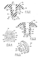
Referring to FIGS. 1-5, the seat ring 76 concentrically surrounds a semi-tubular
portion 78 of a duckbill or mushroom shaped dual check valve 80. The tubular
portion 78 is disposed within the outlet bore 73, projecting downward into the bore from
a radially enlarged annular portion 82 of the valve 80 to a distal end 83 of the semi-tubular
portion 78. Portion 78 has a tubular engaging segment 84 attached unitarily to
the annular portion 82 at one axial end and stepping radially down or inward to a
converging segment 85 of the semi-tubular portion 78 at the opposite axial end. The
engaging segment 84 has a substantially cylindrical outward surface which defines an
outer circumferential groove 86 that sealably receives the radially inward projecting
annular end portion 75 of the seat ring 76.
The seat ring 76 has a substantially tubular and cylindrical under portion
77 disposed concentrically and axially beneath the end portion 75. Under portion 77 is
press fitted sealably into the outlet bore 73 and extends further into the outlet bore 73
than the more pliable engaging segment 84 of the dual check valve 80. The under
portion 77 seals radially between the carburetor body 14 and a portion of the engaging
segment 84 disposed beneath the groove 86. During assembly, engagement of the seat
ring 76, via an interference fit, to the carburetor body 14 requires a greater force than
engagement of the dual check valve 80 to the seat ring 76 because more surface area of
the seat ring 76 is in contact with the carburetor body 14 than in contact with the dual
check valve 80, or because the seat ring 76 is made of a harder material (such as plastic)
than the resilient dual check valve 80. This assures the seat ring 76 remains in place
when the dual check valve 80 is press fitted into the seat ring 76.
Referring to FIGS. 1 and 3-5, to achieve a seal, an inner diameter of the
under portion 77 of the seat ring 76 is equal to, or slightly less than an outer diameter 89
of the engaging segment 84. To allow for radial expansion of the converging segment 85
when the dual check valve 80 opens, a semi-annular space 79 is defined radially and
substantially concentrically between the under portion 77 of the seat ring 76 and the
converging segment 85. The axial cross-section of semi-annular space 79 is most narrow
and forms a true annular shape when measured at or near the engaging segment 84,
defined between the outer diameter 89 and a smaller diameter 88 of the converging
segment 85.
Two exterior, opposite facing, and slightly concave yet substantially
planar faces 90 extend the axial length of the converging segment 85 and converge
toward one-another from the engaging segment 84 to the distal end 83. The distal end 83
has an orifice or slit 92 disposed substantially parallel to the faces 90. Slit 92 is biased
closed, but will open against the resilient force of the converging segment 85 when the
pressure in the pump chamber 66 is adequately greater than the pressure within the outlet
passage 70.
Reinforcing the converging segment 85 of the tubular portion 78 and
projecting radially or laterally outward along the entire axial length of each face 90 is a
longitudinal rib 93. Rib 93 has a distal edge 94 wherein the distance between the distal
edges 94 of the two ribs 93 is substantially equal to diameter 88. The subsequent space
79 between the distal edge 94 of the longitudinal rib 93 and the seat ring 76 permits the
diametrically opposed ribs to flex radially outward as the slit 92 opens against the
resilient force of the ribs 93 due to an adequate pressure differential created across the
converging segment 85 of the dual check valve 80 as the resilient domed cap 64 is
manually depressed. The reinforcement longitudinal ribs 93 prevent unwanted fuel
recirculation flow through the slit 92 due to minor pressure differentials created by
changing pressure, or a vacuum, in the remote fuel tank.
A head 96 of the dual check valve 80 is engaged to the annular portion 82
of the tubular portion 78 and projects laterally or radially outward to encircle and cover
or isolate the inlet port 74. Since the inlet port 74 is annular in shape and surrounds the
outlet port 73, as previously discussed, the head 96 is preferably annular in shape and
extends radially outward from the annular portion 82 to an outer perimeter edge 98 of the
head 96 to operably cover and encircle the annular inlet port 74. As the head projects
radially outward, it bends approximately ninety degrees so that the outer perimeter edge
98 faces and seals to the seat 68 when the pump chamber 66 pressure is greater than the
inlet passage 71 pressure. The head 96 pivots or flexes outward away from the seat 68
causing the outer perimeter edge 98 to lift away from the seat 68 when the pump
chamber 66 pressure is less than the inlet passage 71 pressure. This differential pressure
condition exists after the depressed dome cap 64 has been released and is in the process
of restoring itself to its unflexed natural domed state.
During manual operation of the priming pump 62, the dual check valve 80
of the priming pump 62 allows fuel flow in a first direction, as depicted by the arrows in
Figure 1, and prevents fuel flow in the reverse direction. When the resilient dome cap 66
is depressed, air, vapor and/or liquid fuel is expelled through the center and slit 92 of the
check valve 80 and through the outlet passage 70. By depressing the resilient domed cap
64, the volume of the pump chamber 66 is decreased and pressure is increased causing
the rib reinforced slit 92 to open expelling air, vapor and/or fuel from the chamber 66
into the outlet passage 70. Upon release of the flexed domed cap 64, the chamber 66
volume begins to increase causing a vacuum, draw, or low pressure relative to the
pressure of the inlet passage 71. Consequently, the head 96 flexes outward during
domed cap 64 restoration and the slit 92 closes as a result of the rib 93 bias and pressure
differential. With the head 96 flexed outward, the inlet passage 71 is open causing air,
vapor and/or fuel to flow from the metering chamber 44, through the inlet passage 71,
and into the pump chamber 66, thereby removing any air or fuel vapor from the metering
chamber 44 and the chamber 32 of the diaphragm pump. When the domed cap 64 is
fully extended, or in its unflexed natural state, the inlet passage 71 and the outlet passage
70 are closed and isolated from the pump chamber 66 via the resilient dual check valve
80.
During operation or running of the engine, any vacuum or sub-atmospheric
pressure created within the fuel tank and communicated through the outlet
passage 70 will cause a pressure differential between the outlet passage 70 and the higher
pressure in the pump chamber 66. The orifice 92, however, will remain closed due to the
bias and resistance to flexing of the reinforcement ribs 93 preventing unwanted air
fuel/air mixture and /or liquid fuel flow into the pump chamber 66 from the jets 17, 18
and/or fuel metering chamber 44.
While the forms of the invention herein disclosed constitute a presently
preferred embodiment, many others are possible. For instance, the primary pump 62
including the dual check valve 80 can be remotely located from the carburetor with
utilization of tubing or hoses to extend the necessary passages. It is not intended herein
to mention all the possible equivalent forms or ramification of the invention. It is
understood that terms used herein are merely descriptive, rather than limiting, and that
various changes may be made without departing from the spirit or scope of the invention.
Claims (13)
- A carburetor primer fuel pump for an internal combustion engine comprising:a resilient valve having a head and an integral tubular portion having an engaging segment and a converging segment having a rib and a distal end having a self sealing orifice, the converging segment projecting and converging from the engaging segment to the distal end, the distal end defining the orifice, the rib extending longitudinally along and projecting laterally outward from the converging segment, and the head encircling and projecting radially outward of the tubular portion;a seat body having an outlet port and an inlet port, the converging segment and distal end of the valve disposed in the outlet port, the engaging segment engaged sealably to the seat, and the head encircling the inlet passage; anda resilient domed cap defining a pump chamber, the head and engaging segment of the valve disposed within the pump chamber, the inlet and outlet ports being in communication with the pump chamber through the valve.
- The carburetor fule pump set forth in claim 1 further comprising:a carburetor body having the seat;an outlet passage carried by the carburetor body and communicating with the outlet port; andan inlet passage carried by the carburetor body and communicating with the inlet port.
- The carburetor fuel pump set forth in claim 2 wherein the engaging segment is disposed between the head and the converging segment.
- The carburetor fuel pump set forth in claim 3 wherein the engagement segment is sealably engaged to the carburetor body within the outlet port, and the converging segment is disposed within the outlet port.
- The carburetor fuel pump set forth in claim 4 wherein the orifice is a linear slit and the rib is one of two opposing ribs both extending laterally outward in opposite directions.
- The carburetor fuel pump set forth in claim 5 wherein the two opposing ribs each have a longitudinally extending distal edge spaced away from the carburetor body within the outlet port.
- The carburetor fuel pump set forth in claim 2 further comprising
the seat being an exterior surface of the carburetor body, the domed cap engaged to the surface; and
the resilient head projecting laterally outward from the engaging segment of the valve, the head having an outer perimeter edge constructed and arranged to normally engage the surface and flex away from the surface when the inlet passage pressure is greater than the chamber pressure, the inlet port of the inlet passage being normally encompassed by the perimeter edge. - The carburetor fuel pump set forth in claim 7 further comprising a seat ring engaged directly to the carburetor body within the outlet port, the seat ring projecting axially outward from the outlet port.
- The carburetor fuel pump set forth in claim 8 wherein the inlet port is annular in shape and concentrically disposed about the outlet port, the inlet port being defined radially inwardly by the projecting seat ring and outwardly by the carburetor body.
- The carburetor fuel pump set forth in claim 9 wherein the head is annular in shape and is disposed concentrically about the engaging segment of the tubular portion, the outer perimeter of the head being in sealable contact with the surface of the carburetor body radially outward from the inlet port.
- The carburetor fuel pump set forth in claim 10 wherein the seat ring has a radially inward projecting end portion received sealably in a groove defined by the engaging portion of the valve.
- The carburetor fuel pump set forth in claim 1 wherein the orifice is a linear slit and the rib is one of two opposing ribs both extending laterally outward in opposite directions.
- The carburetor fuel pump set forth in claim 12 wherein the converging segment has two opposite faces converging inwardly from the engaging segment to the distal end, and wherein one of the two opposing ribs project transversely from each face.
Applications Claiming Priority (2)
| Application Number | Priority Date | Filing Date | Title |
|---|---|---|---|
| US971839 | 2001-10-05 | ||
| US09/971,839 US6533254B1 (en) | 2001-10-05 | 2001-10-05 | Carburetor fuel pump |
Publications (1)
| Publication Number | Publication Date |
|---|---|
| EP1300575A2 true EP1300575A2 (en) | 2003-04-09 |
Family
ID=25518857
Family Applications (1)
| Application Number | Title | Priority Date | Filing Date |
|---|---|---|---|
| EP02022129A Withdrawn EP1300575A2 (en) | 2001-10-05 | 2002-10-02 | Carburetor fuel pump |
Country Status (3)
| Country | Link |
|---|---|
| US (1) | US6533254B1 (en) |
| EP (1) | EP1300575A2 (en) |
| JP (1) | JP4149225B2 (en) |
Cited By (2)
| Publication number | Priority date | Publication date | Assignee | Title |
|---|---|---|---|---|
| CN102410116A (en) * | 2011-12-19 | 2012-04-11 | 芜湖盛力制动有限责任公司 | Manual fuel delivery pump of diesel engine fuel system of commercial vehicle |
| CN104653367A (en) * | 2013-11-19 | 2015-05-27 | 安德烈·斯蒂尔股份两合公司 | Handheld work apparatus having a pump, said pump and pump bellows therefor |
Families Citing this family (19)
| Publication number | Priority date | Publication date | Assignee | Title |
|---|---|---|---|---|
| US6799545B2 (en) * | 2002-06-03 | 2004-10-05 | Zama Japan | Carburetor start pump circuit |
| US7243676B2 (en) * | 2004-05-19 | 2007-07-17 | Vernay Laboratories, Inc. | Combination umbrella and inverted bi-directional valve |
| JP4955199B2 (en) * | 2004-09-17 | 2012-06-20 | 株式会社ニッキ | Diaphragm pump |
| US7467785B2 (en) * | 2006-09-08 | 2008-12-23 | Walbro Engine Management, L.L.C. | Auxiliary fuel and air supply in a carburetor |
| US7690342B2 (en) * | 2007-01-05 | 2010-04-06 | Walbro Engine Management, L.L.C. | Priming circuit for a fuel system |
| US8739842B2 (en) * | 2009-10-19 | 2014-06-03 | Veeder-Root Company | Method for adjusting air to liquid ratio in vapor recovery system |
| JP2011236743A (en) * | 2010-04-30 | 2011-11-24 | Hitachi Koki Co Ltd | Engine and engine operating machine including the same |
| JP5666855B2 (en) * | 2010-09-03 | 2015-02-12 | ザマ・ジャパン株式会社 | Starter and vaporizer using the same |
| WO2012141633A1 (en) | 2011-04-15 | 2012-10-18 | Husqvarna Ab | A carburetor system for a carburetor engine |
| US9062630B2 (en) | 2011-11-15 | 2015-06-23 | Walbro Engine Management, L.L.C. | Carburetor fuel supply system |
| US9062629B2 (en) | 2011-11-15 | 2015-06-23 | Walbro Engine Management, L. L.C. | Carburetor fuel supply system |
| WO2014052385A1 (en) * | 2012-09-28 | 2014-04-03 | Walbro Engine Management, L.L.C. | Carburetor supplemental fuel supply |
| CN103527368B (en) * | 2013-09-18 | 2016-06-08 | 浙江亚特电器有限公司 | A kind of engine pump oil machine structure |
| US9599066B2 (en) * | 2014-02-28 | 2017-03-21 | Walbro Llc | Carburetor with low flow rate fluid passage |
| US10562579B2 (en) | 2015-07-09 | 2020-02-18 | Polaris Industries Inc. | Pressure compensator for meter housing |
| US10175068B2 (en) * | 2015-07-09 | 2019-01-08 | Polaris Industries Inc. | Pressure compensator for meter housing |
| US20190024614A1 (en) * | 2016-01-08 | 2019-01-24 | Tti (Macao Commercial Offshore) Limited | Carburetor with maintenance port |
| US10228067B2 (en) * | 2016-01-21 | 2019-03-12 | Übertüb Inc. | Valve assembly for inflatable bodies |
| CN106555708B (en) * | 2016-09-30 | 2020-01-07 | 浙江瑞星化油器制造有限公司 | Simple starting device and starting method for oil-rich gasifier |
Family Cites Families (14)
| Publication number | Priority date | Publication date | Assignee | Title |
|---|---|---|---|---|
| US1952437A (en) * | 1932-08-05 | 1934-03-27 | Ward I Huber | Dispensing device for liquid containers |
| US3275305A (en) * | 1965-05-03 | 1966-09-27 | Tillotson Mfg Co | Fuel feed and charge forming apparatus with priming device |
| US3983857A (en) * | 1975-02-26 | 1976-10-05 | Walbro Corporation | Combination primer and pump for internal combustion engines |
| US4341239A (en) * | 1980-07-14 | 1982-07-27 | Vernay Laboratories, Inc. | Combination check-overpressure relief valve |
| US4436519A (en) * | 1981-05-28 | 1984-03-13 | Argon Medical Corp. | Removable hemostasis valve |
| US4612960A (en) * | 1985-02-21 | 1986-09-23 | Vernay Laboratories, Inc. | Valve assembly |
| JP2527983B2 (en) * | 1987-12-04 | 1996-08-28 | 株式会社ウオルブローフアーイースト | Vaporizer starting fuel supply device |
| US4824613A (en) * | 1988-01-25 | 1989-04-25 | Tillotson, Ltd. | Vapor return primer for carburetors of internal combustion engines |
| US4926808A (en) * | 1989-06-08 | 1990-05-22 | Tecumseh Products Company | Primer bulb check valve system for an internally vented bowl primer carburetor |
| US5010925A (en) | 1990-04-09 | 1991-04-30 | Vernay Laboratories, Inc. | Normally closed duckbill valve assembly |
| US5301707A (en) | 1993-04-12 | 1994-04-12 | Vernay Laboratories, Inc. | Anti-whistling duckbill valve |
| US5507318A (en) | 1994-10-04 | 1996-04-16 | Walbro Corporation | Umbrella check valves |
| US5711901A (en) | 1996-06-05 | 1998-01-27 | Walbro Corporation | Carburetor having temperature-compensated purge/primer |
| US6374810B1 (en) * | 2000-01-13 | 2002-04-23 | Walbro Corporation | Fuel and air purge system for diaphragm carburetors |
-
2001
- 2001-10-05 US US09/971,839 patent/US6533254B1/en not_active Expired - Lifetime
-
2002
- 2002-10-02 EP EP02022129A patent/EP1300575A2/en not_active Withdrawn
- 2002-10-02 JP JP2002289651A patent/JP4149225B2/en not_active Expired - Fee Related
Cited By (3)
| Publication number | Priority date | Publication date | Assignee | Title |
|---|---|---|---|---|
| CN102410116A (en) * | 2011-12-19 | 2012-04-11 | 芜湖盛力制动有限责任公司 | Manual fuel delivery pump of diesel engine fuel system of commercial vehicle |
| CN104653367A (en) * | 2013-11-19 | 2015-05-27 | 安德烈·斯蒂尔股份两合公司 | Handheld work apparatus having a pump, said pump and pump bellows therefor |
| CN104653367B (en) * | 2013-11-19 | 2018-10-23 | 安德烈·斯蒂尔股份两合公司 | Hand-held power tool, pump with pump and pump retractable sack |
Also Published As
| Publication number | Publication date |
|---|---|
| JP2003120421A (en) | 2003-04-23 |
| US6533254B1 (en) | 2003-03-18 |
| JP4149225B2 (en) | 2008-09-10 |
Similar Documents
| Publication | Publication Date | Title |
|---|---|---|
| US6533254B1 (en) | Carburetor fuel pump | |
| US5507318A (en) | Umbrella check valves | |
| US4447370A (en) | Supplementary fuel supply mechanism for internal combustion engines | |
| CN101139957A (en) | Supplies auxiliary fuel and air in the carburetor | |
| US6715737B2 (en) | Fuel metering system for a carburetor | |
| US6561495B2 (en) | Carburetor fuel priming pump with integral fuel bowl drain | |
| EP0247276B1 (en) | Carburation system for an internal combustion engine | |
| US6000369A (en) | Starting system for diaphragm carburetor | |
| US6536747B2 (en) | Carburetor vent control | |
| EP1026389A2 (en) | Carburetor with accelerating device | |
| US4168288A (en) | Combined carburetor and impulse fuel pump | |
| EP1094215A2 (en) | Acceleration device for a two-cycle engine | |
| US4104994A (en) | Charge forming method and apparatus with accelerating system | |
| EP0401480B1 (en) | Primer bulb check valve system for an internally vented bowl primer carburetor | |
| US5843345A (en) | Pneumatic accelerator for low emission charge forming devices | |
| EP0478330B1 (en) | Floatless carburetor with integral primer system | |
| EP1045134B1 (en) | Carburetor with vapor purge pump | |
| CA2270786C (en) | Carburetor having extended prime | |
| AU2001296759B2 (en) | Priming system for an engine carburetor | |
| AU2001296759A1 (en) | Priming system for an engine carburetor | |
| US7287743B1 (en) | Carburetor with an air bleed passage | |
| US3235238A (en) | Carburetor | |
| US7172178B1 (en) | Carburetor with acceleration fuel pump | |
| US12123374B2 (en) | Fuel supply device with injector and vapor management | |
| JPS60195365A (en) | Diaphragm type carburettor |
Legal Events
| Date | Code | Title | Description |
|---|---|---|---|
| PUAI | Public reference made under article 153(3) epc to a published international application that has entered the european phase |
Free format text: ORIGINAL CODE: 0009012 |
|
| AK | Designated contracting states |
Kind code of ref document: A2 Designated state(s): AT BE BG CH CY CZ DE DK EE ES FI FR GB GR IE IT LI LU MC NL PT SE SK TR Designated state(s): AT BE BG CH CY CZ DE DK EE ES FI FR GB GR IE IT LI LU MC NL PT SE SK TR |
|
| AX | Request for extension of the european patent |
Extension state: AL LT LV MK RO SI |
|
| STAA | Information on the status of an ep patent application or granted ep patent |
Free format text: STATUS: THE APPLICATION IS DEEMED TO BE WITHDRAWN |
|
| 18D | Application deemed to be withdrawn |
Effective date: 20050501 |