EP1300229A1 - Connected fastening members and process for production of resin molded article with fastening member - Google Patents
Connected fastening members and process for production of resin molded article with fastening member Download PDFInfo
- Publication number
- EP1300229A1 EP1300229A1 EP02021693A EP02021693A EP1300229A1 EP 1300229 A1 EP1300229 A1 EP 1300229A1 EP 02021693 A EP02021693 A EP 02021693A EP 02021693 A EP02021693 A EP 02021693A EP 1300229 A1 EP1300229 A1 EP 1300229A1
- Authority
- EP
- European Patent Office
- Prior art keywords
- fastening members
- mold
- fastening
- recess
- resin
- Prior art date
- Legal status (The legal status is an assumption and is not a legal conclusion. Google has not performed a legal analysis and makes no representation as to the accuracy of the status listed.)
- Granted
Links
Images


Classifications
-
- B—PERFORMING OPERATIONS; TRANSPORTING
- B29—WORKING OF PLASTICS; WORKING OF SUBSTANCES IN A PLASTIC STATE IN GENERAL
- B29C—SHAPING OR JOINING OF PLASTICS; SHAPING OF MATERIAL IN A PLASTIC STATE, NOT OTHERWISE PROVIDED FOR; AFTER-TREATMENT OF THE SHAPED PRODUCTS, e.g. REPAIRING
- B29C39/00—Shaping by casting, i.e. introducing the moulding material into a mould or between confining surfaces without significant moulding pressure; Apparatus therefor
- B29C39/02—Shaping by casting, i.e. introducing the moulding material into a mould or between confining surfaces without significant moulding pressure; Apparatus therefor for making articles of definite length, i.e. discrete articles
- B29C39/10—Shaping by casting, i.e. introducing the moulding material into a mould or between confining surfaces without significant moulding pressure; Apparatus therefor for making articles of definite length, i.e. discrete articles incorporating preformed parts or layers, e.g. casting around inserts or for coating articles
-
- B—PERFORMING OPERATIONS; TRANSPORTING
- B29—WORKING OF PLASTICS; WORKING OF SUBSTANCES IN A PLASTIC STATE IN GENERAL
- B29C—SHAPING OR JOINING OF PLASTICS; SHAPING OF MATERIAL IN A PLASTIC STATE, NOT OTHERWISE PROVIDED FOR; AFTER-TREATMENT OF THE SHAPED PRODUCTS, e.g. REPAIRING
- B29C33/00—Moulds or cores; Details thereof or accessories therefor
- B29C33/12—Moulds or cores; Details thereof or accessories therefor with incorporated means for positioning inserts, e.g. labels
- B29C33/14—Moulds or cores; Details thereof or accessories therefor with incorporated means for positioning inserts, e.g. labels against the mould wall
- B29C33/16—Moulds or cores; Details thereof or accessories therefor with incorporated means for positioning inserts, e.g. labels against the mould wall using magnetic means
-
- B—PERFORMING OPERATIONS; TRANSPORTING
- B29—WORKING OF PLASTICS; WORKING OF SUBSTANCES IN A PLASTIC STATE IN GENERAL
- B29C—SHAPING OR JOINING OF PLASTICS; SHAPING OF MATERIAL IN A PLASTIC STATE, NOT OTHERWISE PROVIDED FOR; AFTER-TREATMENT OF THE SHAPED PRODUCTS, e.g. REPAIRING
- B29C44/00—Shaping by internal pressure generated in the material, e.g. swelling or foaming ; Producing porous or cellular expanded plastics articles
- B29C44/02—Shaping by internal pressure generated in the material, e.g. swelling or foaming ; Producing porous or cellular expanded plastics articles for articles of definite length, i.e. discrete articles
- B29C44/12—Incorporating or moulding on preformed parts, e.g. inserts or reinforcements
- B29C44/1261—Avoiding impregnation of a preformed part
-
- B—PERFORMING OPERATIONS; TRANSPORTING
- B29—WORKING OF PLASTICS; WORKING OF SUBSTANCES IN A PLASTIC STATE IN GENERAL
- B29C—SHAPING OR JOINING OF PLASTICS; SHAPING OF MATERIAL IN A PLASTIC STATE, NOT OTHERWISE PROVIDED FOR; AFTER-TREATMENT OF THE SHAPED PRODUCTS, e.g. REPAIRING
- B29C45/00—Injection moulding, i.e. forcing the required volume of moulding material through a nozzle into a closed mould; Apparatus therefor
- B29C45/14—Injection moulding, i.e. forcing the required volume of moulding material through a nozzle into a closed mould; Apparatus therefor incorporating preformed parts or layers, e.g. injection moulding around inserts or for coating articles
- B29C45/14467—Joining articles or parts of a single article
-
- B—PERFORMING OPERATIONS; TRANSPORTING
- B29—WORKING OF PLASTICS; WORKING OF SUBSTANCES IN A PLASTIC STATE IN GENERAL
- B29L—INDEXING SCHEME ASSOCIATED WITH SUBCLASS B29C, RELATING TO PARTICULAR ARTICLES
- B29L2031/00—Other particular articles
- B29L2031/727—Fastening elements
- B29L2031/729—Hook and loop-type fasteners
-
- Y—GENERAL TAGGING OF NEW TECHNOLOGICAL DEVELOPMENTS; GENERAL TAGGING OF CROSS-SECTIONAL TECHNOLOGIES SPANNING OVER SEVERAL SECTIONS OF THE IPC; TECHNICAL SUBJECTS COVERED BY FORMER USPC CROSS-REFERENCE ART COLLECTIONS [XRACs] AND DIGESTS
- Y10—TECHNICAL SUBJECTS COVERED BY FORMER USPC
- Y10S—TECHNICAL SUBJECTS COVERED BY FORMER USPC CROSS-REFERENCE ART COLLECTIONS [XRACs] AND DIGESTS
- Y10S428/00—Stock material or miscellaneous articles
- Y10S428/90—Magnetic feature
-
- Y—GENERAL TAGGING OF NEW TECHNOLOGICAL DEVELOPMENTS; GENERAL TAGGING OF CROSS-SECTIONAL TECHNOLOGIES SPANNING OVER SEVERAL SECTIONS OF THE IPC; TECHNICAL SUBJECTS COVERED BY FORMER USPC CROSS-REFERENCE ART COLLECTIONS [XRACs] AND DIGESTS
- Y10—TECHNICAL SUBJECTS COVERED BY FORMER USPC
- Y10T—TECHNICAL SUBJECTS COVERED BY FORMER US CLASSIFICATION
- Y10T24/00—Buckles, buttons, clasps, etc.
- Y10T24/27—Buckles, buttons, clasps, etc. including readily dissociable fastener having numerous, protruding, unitary filaments randomly interlocking with, and simultaneously moving towards, mating structure [e.g., hook-loop type fastener]
-
- Y—GENERAL TAGGING OF NEW TECHNOLOGICAL DEVELOPMENTS; GENERAL TAGGING OF CROSS-SECTIONAL TECHNOLOGIES SPANNING OVER SEVERAL SECTIONS OF THE IPC; TECHNICAL SUBJECTS COVERED BY FORMER USPC CROSS-REFERENCE ART COLLECTIONS [XRACs] AND DIGESTS
- Y10—TECHNICAL SUBJECTS COVERED BY FORMER USPC
- Y10T—TECHNICAL SUBJECTS COVERED BY FORMER US CLASSIFICATION
- Y10T24/00—Buckles, buttons, clasps, etc.
- Y10T24/32—Buckles, buttons, clasps, etc. having magnetic fastener
-
- Y—GENERAL TAGGING OF NEW TECHNOLOGICAL DEVELOPMENTS; GENERAL TAGGING OF CROSS-SECTIONAL TECHNOLOGIES SPANNING OVER SEVERAL SECTIONS OF THE IPC; TECHNICAL SUBJECTS COVERED BY FORMER USPC CROSS-REFERENCE ART COLLECTIONS [XRACs] AND DIGESTS
- Y10—TECHNICAL SUBJECTS COVERED BY FORMER USPC
- Y10T—TECHNICAL SUBJECTS COVERED BY FORMER US CLASSIFICATION
- Y10T24/00—Buckles, buttons, clasps, etc.
- Y10T24/33—Buckles, buttons, clasps, etc. having adhesive fastener
-
- Y—GENERAL TAGGING OF NEW TECHNOLOGICAL DEVELOPMENTS; GENERAL TAGGING OF CROSS-SECTIONAL TECHNOLOGIES SPANNING OVER SEVERAL SECTIONS OF THE IPC; TECHNICAL SUBJECTS COVERED BY FORMER USPC CROSS-REFERENCE ART COLLECTIONS [XRACs] AND DIGESTS
- Y10—TECHNICAL SUBJECTS COVERED BY FORMER USPC
- Y10T—TECHNICAL SUBJECTS COVERED BY FORMER US CLASSIFICATION
- Y10T428/00—Stock material or miscellaneous articles
- Y10T428/19—Sheets or webs edge spliced or joined
- Y10T428/192—Sheets or webs coplanar
- Y10T428/197—Sheets or webs coplanar with noncoplanar reinforcement
-
- Y—GENERAL TAGGING OF NEW TECHNOLOGICAL DEVELOPMENTS; GENERAL TAGGING OF CROSS-SECTIONAL TECHNOLOGIES SPANNING OVER SEVERAL SECTIONS OF THE IPC; TECHNICAL SUBJECTS COVERED BY FORMER USPC CROSS-REFERENCE ART COLLECTIONS [XRACs] AND DIGESTS
- Y10—TECHNICAL SUBJECTS COVERED BY FORMER USPC
- Y10T—TECHNICAL SUBJECTS COVERED BY FORMER US CLASSIFICATION
- Y10T428/00—Stock material or miscellaneous articles
- Y10T428/24—Structurally defined web or sheet [e.g., overall dimension, etc.]
- Y10T428/24008—Structurally defined web or sheet [e.g., overall dimension, etc.] including fastener for attaching to external surface
- Y10T428/24017—Hook or barb
-
- Y—GENERAL TAGGING OF NEW TECHNOLOGICAL DEVELOPMENTS; GENERAL TAGGING OF CROSS-SECTIONAL TECHNOLOGIES SPANNING OVER SEVERAL SECTIONS OF THE IPC; TECHNICAL SUBJECTS COVERED BY FORMER USPC CROSS-REFERENCE ART COLLECTIONS [XRACs] AND DIGESTS
- Y10—TECHNICAL SUBJECTS COVERED BY FORMER USPC
- Y10T—TECHNICAL SUBJECTS COVERED BY FORMER US CLASSIFICATION
- Y10T428/00—Stock material or miscellaneous articles
- Y10T428/24—Structurally defined web or sheet [e.g., overall dimension, etc.]
- Y10T428/24479—Structurally defined web or sheet [e.g., overall dimension, etc.] including variation in thickness
- Y10T428/24521—Structurally defined web or sheet [e.g., overall dimension, etc.] including variation in thickness with component conforming to contour of nonplanar surface
- Y10T428/24537—Parallel ribs and/or grooves
Definitions
- the present invention relates to a mold-in fastening member to be embedded in the surface of a molded resin article such as automotive seat cushions and office chair cushions.
- the fastening member embedded in the cushion is useful to manufacture automotive seats or office chairs by fixing an upholstery material such as cloth to the cushion.
- An automotive seat or office chair seat is generally produced by covering the surface of a cushion made of foamed polyurethane or the like with a seat cover (upholstery material).
- a so-called Hogring method has been employed, in which a cushion having molded-in wires is produced by embedding wires retained in a recess of a mold into the cushion, and the seat cover is attached to the cushion by means of a large number of metal fixing members which engage the molded-in wires with the seat cover.
- the procedure of the Hogring method is accomplished by the aid of an electric tool.
- An object of the present invention is to provide connected fastening members which enable to simultaneously fit a plurality of fastening members to corresponding recessed portions of a mold in a single operation.
- the present invention provides connected fastening members comprising a plurality of mold-in fastening members each comprising a substrate, a front surface having a number of engaging elements, and a back surface with no engaging element; and a flexible connecting means for connecting the mold-in fastening members, the mold-in fastening members being arranged in juxtaposition, and the flexible connecting means being disposed so as to cover at least a part of the back surface of each mold-in fastening member.
- the mold-in fastening members are disposed with their lengthwise ends spaced from each other at predetermined intervals, or disposed substantially in close contact with each other without leaving space between the lengthwise ends.
- the connecting means preferably comprises a resin molded article, or a porous material.
- the present invention also provides a process for producing a molded article with fastening members, comprising (1) fitting each fastening member of the connected fastening members mentioned above to a corresponding recess formed in a mold with the engaging elements facing a bottom surface of the recess; (2) injecting a resin into the mold; and (3) curing the resin.
- a process for producing a molded article with fastening members comprising (1) fitting each fastening member of the connected fastening members mentioned above to a corresponding recess formed in a mold with the engaging elements facing a bottom surface of the recess; (2) injecting a resin into the mold; and (3) curing the resin.
- the mold-in fastening members are disposed with their lengthwise ends spaced from each other at predetermined intervals, or disposed substantially in close contact with each other without leaving space between the lengthwise ends.
- Fig. 1 illustrates a plan view showing an arrangement of a plurality of recessed portions at an inner bottom of a mold.
- five recessed portions 2 through 6 are arranged in H shape on the inner bottom 1 of the mold.
- Tape-like fastening members are fit to the respective recessed portions, with the front surface (engaging surface) down.
- the arrangement shown in Fig. 1 is for receiving connected fastening members comprising a plurality of mold-in fastening members that are disposed with their lengthwise ends spaced from each other at predetermined distances and connected together by a flexible connecting means at back surfaces.
- Connected fastening members for this arrangement have two paralleled long fastening members and a fastening member corresponding to the recessed portion 3 which is interposed between and closely to the mid portions of the long fastening members in a shunt configuration. Namely, in the connected fastening members for this recess arrangement, two fastening members are connected at one connecting portion.
- Fig. 2 illustrates a plan view showing a fastening member to be connected.
- Fig. 3 illustrates a sectional view of the fastening member taken along the line A-A' of Fig. 2.
- the fastening member used in the present invention comprises a substrate 7 and a number of engaging elements 9, 9' provided on a front surface 8 of the substrate. Each engaging element has a bulged head portion of a mushroom-shape, an arrowhead-shape or a hook-shape.
- the engaging elements on the surface of the fastening member engage with loop elements formed on a back surface of an upholstery material mentioned below to closely secure the upholstery material onto the molded article.
- a back surface 10 of the substrate may be flat as shown in Fig. 3.
- continuous ridges (not shown) which serve as anchoring elements for the resin molded article may be formed on the back surface. With the anchoring elements on the back surface, the fastening members can be firmly bonded to the resin molded article.
- a continuous groove (shown by B in Figs. 2 and 3) may be formed along lateral sides so as to allow the lateral side portions to bend flexibly against the substrate body. By providing such continuous grooves, the lateral side portions can closely contact the shoulder of the recessed portion of a mold.
- the continuous groove may be formed on either of the front and back surfaces.
- the substrate may be provided on the front or back surface thereof with a ferrite-containing resin layer so as to easily fit the connected fastening members to a mold by magnetic attraction of magnets embedded in the bottom of corresponding recessed portions of the mold.
- This modification is also effective for preventing a liquid resin from penetrating into the recessed portion.
- the fastening member of the present invention may be made of thermoplastic resins such as polyolefin resins, polyester resins and polyamide resins.
- thermoplastic resins such as polyolefin resins, polyester resins and polyamide resins.
- the polyolefin resins typically polypropylene, are preferred in view of moldability and flexibility.
- the detailed structure of the fastening member may be selected depending on its applications.
- the fastening member when applied to automotive seats, the fastening member usually has a width of 5 to 50 mm, preferably 10 to 30 mm, and a length of 10 to 100 cm, preferably 15 to 70 cm.
- the thickness of the substrate is preferably 0.2 to 1.0 mm, more preferably 0.3 to 0.7 mm.
- the height of each engaging element is not particularly restricted, and preferably 1 to 10 mm, more preferably 1.5 to 6 mm.
- the engaging elements may be arranged in a single row or in a plurality of rows depending on the width of the substrate.
- the density of the engaging elements is preferably 30 to 100 per cm 2 .
- the anchoring elements in the form of continuous ridges may be arranged in a single row or in a plurality of rows on the back surface of the substrate.
- the fastening member may be produced by melt-extruding the above thermoplastic resin through a nozzle with suitable slits to form a tape provided on its front surface with a row of continuous ridges; making a number of cuts along each continuous ridge at small intervals; and then drawing the tape in the lengthwise direction to form a number of engaging elements on the front surface.
- the fastening member may be produced in the same manner as above except for forming continuous ridges for the anchoring elements using a nozzle having slits corresponding to each anchoring element.
- Fig. 4 illustrates a plan view showing an embodiment of the connected fastening members according to the present invention as viewed from the back surface (from the side opposite to the surface with engaging elements).
- Five fastening members 11-15 arranged in H-shape are connected together by connecting members 16 and 17 at portions where lengthwise ends of the fastening members are gathered together.
- Two of the fastening members are connected at the lateral edge of one and the lengthwise end of the other, or connected at the butting lengthwise ends of two.
- all the five fastening members are connected together at the lengthwise ends thereof.
- Two or more fastening members are connected together by a single connecting means.
- three or four fastening members are connected together by a single connecting means.
- two or three fastening members are connected together by a single connecting means.
- two or three fastening members are connected together by a single connecting means.
- the fastening members may be connected leaving no gap therebetween.
- a plurality of fastening members are disposed such that the lengthwise ends thereof are spaced from each other at predetermined intervals.
- the fastening members are imbricately disposed, for example, disposed one on another without leaving a space, there occurs the difference in level. Therefore, care must be taken during the mold-in forming to prevent undesired penetration of a liquid resin to the surface of the substrate with engaging elements. By connecting the fastening members butting at each other without leaving a gap, the difference in level can be avoided.
- FIG. 5 is a plan view showing an embodiment of the connected fastening members of the present invention as viewed from the front surface with engaging elements.
- Five fastening members 21-25 are connected together by two connecting means 26, 27. More specifically, two fastening members 21, 23 vertically aligned are connected with the transversely arranged fastening member 22 without leaving gap therebetween and without making difference in level between the substrate surfaces.
- Each of the fastening members is provided on the front surface thereof with a number of engaging elements (hook-like elements) 28, 29.
- the fastening members shown in Figs. 5, 7 and 9 are also preferably provided, as described above, at each of the opposite lateral side portions with a groove (not shown) continuously extending along the longitudinal direction for rendering the lateral side portion flexible against the substrate body.
- the groove at the boundary between the lateral side portion and the substrate extremely reduce the thickness of the substrate to allow the lateral side portion to easily bend against the substrate body.
- the lateral side portion closely contacts the shoulder of the recessed portion of a mold to effectively prevent a liquid resin from penetrating into the recessed portion through gaps.
- the grooves may be formed on either or both of the front and back surfaces of the substrate.
- the depth of the groove (total depth of front and back grooves when formed on both the surfaces) is preferably about 40 to 80% of the thickness of the substrate.
- a connecting means 26 is fitted to the back surfaces of the fastening members 21, 22 and 23.
- the other two fastening members 24, 25 aligned vertically and the transversely arranged fastening member 22 are connected by a connecting means 27.
- porous seal members 30, 31 made of fibrous material or foamed resin are provided to allow a liquid molding resin to partially penetrate thereinto through the lengthwise ends.
- the vertically arranged fastening members 21, 23, 24, 25 are similarly provided at their free lengthwise ends with porous seal members 32, 33, 34, 35.
- the liquid resin penetrated into the seal members from the lengthwise ends is foamed and cured therein, thereby preventing the liquid resin from penetrating beyond the seal members.
- the seal members preferably have such a size as can be received in the recessed portion of a mold.
- the connected fastening members shown in Fig. 5 are fit to the recessed portion of a mold as shown in Fig. 6.
- the recessed portion shown in Fig. 6 comprises five recesses 36-40 so configured as to receive the corresponding fastening members 21-25.
- Each recess has a depth enough to receive the fastening member and two shoulders 41, 42 defining the recess.
- each fastening member is fit to the corresponding recess with its both lateral side portions on the shoulders such that the lateral side portions closely contact the shoulders, thereby preventing the liquid molding resin from penetrating into the recess through the gap between the lateral side portions and the shoulders and burying the engaging elements with the resin.
- the thickness of the lateral side portions may be reduced to render the lateral side portions flexible relative to the substrate body.
- This method may also be practically usable as alternative for the formation of the grooves as mentioned above.
- the lengthwise ends 43-48 of the recesses are open ends.
- the opposite lateral side portions of each fastening member are brought into close contact with the shoulders of the corresponding recess.
- the seal members 30, 31 provided at the opposite lengthwise ends of the transversely arranged fastening member 22 prevent the liquid molding resin from penetrating into the recess through the lengthwise ends 44, 47.
- the lengthwise ends of the vertically arranged fastening members 21, 23, 24, 25 are also sealed with seal members 32-35 to prevent the liquid resin from penetrating into the recess through the open ends 43, 45, 46, 48. Further, the fitting of the fastening members to the recesses and the close contact therebetween may be facilitated and ensured by a magnetic attraction between a magnet embedded in the bottom of the recessed portion of a mold and a ferrite-containing layer formed on the fastening members.
- the fastening members may be provided with both the ferrite-containing layer and the grooves.
- the ferrite-containing layer is preferably formed between rows of the engaging elements.
- Fig. 7 illustrates a plan view of another embodiment of the connected fastening members according to the present invention as viewed from the surface having the hook-like engaging elements.
- the fastening members shown in Fig. 7 are connected together in the same manner as in the connected fastening members of Fig. 5 except that the structure of the lengthwise ends of the fastening members is different from that of Fig. 5. Namely, a flat portion is formed at the lengthwise end of each fastening member by partially cutting away the engaging elements from the substrate.
- flat portions 49, 50 are provided, and flat portions 51-54 are provided at the lengthwise ends of the vertically arranged fastening members.
- the other parts of the structure are similar to those shown in Fig. 5.
- Fig. 8 illustrates a recessed portion of a mold for receiving the connected fastening members of Fig. 7, which comprises five recesses integrally and continuously formed.
- the shoulders 41 and 42 of the recess continuously extend along its entire periphery, with no open end.
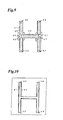
- Fig. 9 illustrates a plan view of a still another embodiment of the connected fastening members according to the present invention as viewed from the surface having the hook-like engaging elements.
- the transversely arranged fastening member 22 is provided at its opposite lengthwise ends with flat portions 56, 57 having no engaging elements.
- a vertically arranged fastening member 21 is connected with the transversely arranged fastening member 22 such that the outer lateral side 55 of the fastening member 21 and the outer left side of the flat portion 56 of the fastening member 22 are continuously aligned in a straight line. This continuous linear alignment is important to fit the connected fastening members to the recessed portion of a mold without leaving a gap.
- the vertically arranged fastening member 21 and the transversely arranged fastening member 22 are connected together by the connecting means 26 so as to be present on the same plane without leaving a gap.
- the connecting portion at right side is similarly formed.
- seal members 32-35 are provided at each lengthwise end of the vertically arranged fastening members. It is sufficient for the present invention that the transversely arranged fastening member is connected with the vertically arranged fastening members at the connecting portion such that the outer side of the flat portion and the outer lateral side of the flexible lateral end portion (lateral end portion that is made flexible by forming the grooves or reducing its thickness) are aligned in a nearly straight line.
- the transversely arranged fastening member may transversely project slightly beyond the outer lateral side of the vertically arranged fastening member.
- the penetration of a liquid resin into the recess can be effectively prevented, for example, in a manner described below.
- the engaging elements in a portion to be brought into butting against the outer shoulder of the recess are removed.
- a magnetic layer is provided so as to bring the both ends of the fastening member and the both outer shoulders of the recess to close contact without leaving a gap by magnetic attraction with magnets disposed on a mold at the portions corresponding to the projecting portions.
- Fig. 10 illustrates a plan view of a recessed portion of a mold for receiving the connected fastening members shown in Fig. 9.
- the recessed portion comprises a continuous H-shaped groove and shoulders 41, 42.
- Two vertical recesses have four open ends 43, 45, 46, 48 at their lengthwise ends.
- the connecting portion between the vertically arranged fastening member and the transversely arranged fastening member the formation of a gap between the fastening member and the shoulder of the recess can be avoided, because the outer lateral side portion of the vertically arranged fastening member 55 and the flat portion 56 at the lengthwise end of the transversely arranged fastening member are continuously connected in the same plane to ensure the close contact between the shoulder of the recess and the outer lateral side portion.
- the other connecting portion has the same structure.
- the open ends 43, 45, 46, 48 of the recess are sealed by the seal members 32-35 at four lengthwise ends of the vertically arranged fastening members.
- Connecting means 26 and 27 are provided to hold the fastening members connected to each other.
- the fastening members shown in Fig. 9 may be provided thereon with ferrite-containing layers to ensure the close contact between the fastening members and the recessed portion by magnetic attraction with magnets disposed in the recessed portion of Fig. 10.
- magnetic attraction it is preferred to make the both lateral side portions flexible by providing grooves as described above between the lateral side portions and the substrate body. Since the lengthwise ends of the recess are open ends, each fastening members of the connected fastening members shown in Fig. 9 is easily fit to the corresponding recess shown in Fig. 10.
- the above three kinds of structures for the connected fastening members and the recessed portion of a mold may be appropriately combined according to the requirements.
- the fastening members are connected with each other by the connecting means attached to their back surfaces with no engaging elements, and as a result thereof, a plurality of connected fastening members are simultaneously fit to a plurality of corresponding recesses of a mold as shown in Fig. 1 in a single operation. Since the connected fastening members are independent and discontinuous from each other, the respective fastening members are fit to the independent recesses of a mold while maintaining a good sealing between the recess and the fastening members. With this structure, since a molding resin being injected into the mold is prevented from penetrating into the recess, i.e., reaching the surface with engaging elements, a problem of burying the engaging elements can be avoided.
- the connecting means used in the present invention is constituted by a molded article or a porous body each made of a flexible resin. A size enough to connect or cover the lengthwise ends of fastening members to be connected is sufficient.
- the shape may be rectangular, circular or elliptical. A shape that fits the contours of the fastening members to be connected is also usable.
- Specific examples of the connecting means are plastic sheets, cloth, non-woven fabric and foamed resin.
- the connected fastening members are fit to the recessed portion of a mold while delicately adjusting relative positions of the fastening members and the recesses. Therefore, the connecting means is required to be flexible. If not flexible, the delicate positioning becomes difficult.
- the connecting element may be a molded article made of a substantially transparent resin to visually monitor the relative positions of the recesses and the fastening members. The fuse bonding between the connecting means and the fastening members can be enhanced by making the both from the same kind of material.
- the connecting means is preferred to have a suitable rigidity.
- the connecting means is bonded to the fastening members by an adhesive, a pressure-sensitive adhesive, or fusion bonding.
- a cloth tape coated with a pressure-sensitive adhesive is a preferred example for the connecting means.
- the bonding is preferably made by an ultrasonic fusion bonding or an induction fusion bonding.
- the back surface of the fastening members is preferred to be substantially flat at the lengthwise ends to be interconnected to the connecting means. If the anchoring elements are formed on the back surface of the substrate, the substrate ends to be connected are made flat by removing the anchoring elements, or by applying heat during the connecting operation.
- the resin molded article with fastening members according to the present invention is produced by fitting the connected fastening members to the recessed portion of a mold; injecting a liquid molding resin such as polyurethane into the mold; and foaming or curing the resin to embed the fastening members in a surface of the resulting molded article while allowing the engaging elements to be laid bare on the surface. It is important to prevent the liquid resin from penetrating into the recess by closely contacting the fastening members and the recess so as to leave no gap therebetween, because the liquid resin penetrating into the recess through a gap buries the engaging elements on the substrate to reduce the engaging function of the engaging elements with the upholstery material covering the molded article.
- a liquid molding resin such as polyurethane
- Prevention of the resin from penetrating into the recess can be attained by known structures, for example, by continuous sealing ridges formed on the front surface of the fastening member along its lateral sides, which are brought into close contact with the longitudinal shoulders of the recess; or by continuous sealing projections outwardly projecting from the back surface of both lateral side portions of the substrate, which are brought into close contact with the inner surface of the recess when the fastening members are fit to the recess.
- the prevention can be further attained by forming grooves on the substrate of the fastening member along the lateral sides to render the lateral side portions flexible relative to the substrate body, and providing ferrite-containing layers on the front or back surface of the fastening member.
- a weir may be provided to the recess at position corresponding to slightly inside the lengthwise end of the fastening member, or a weir may be provided at the lengthwise end of the fastening member.
- the connecting means of the present invention preferably has a structure capable of being firmly bonded to the molding resin since it is embedded therein.
- the connecting means is a plastic molded article
- suitable protrusions serving as anchoring elements against the resin may be provided on the back surface opposite to the surface to which the fastening members are bonded.
- Such protrusions may also serve as grips for handling, resulting in improving the workability for fitting the connected fastening members to the recessed portion of a mold.
- the connecting means is a cloth, a non-woven fabric or a resin foamed body, preferred is a porous structure allowing a liquid molding resin to be partially impregnated thereinto. The impregnated resin is then cured to strongly bond the connecting means to the resin molded article.
- the resin molded article provided at its surface with the fastening members is covered with an upholstery material upon use.
- the upholstery material may be made of cloth, non-woven fabric, artificial leather or the like.
- loop elements are provided on the back surface of the upholstery material, i.e., the surface facing the engaging elements of the fastening members.
- the loop elements are not particularly restricted as long as they are engageable with the bulged head portions of the fastening members, and include, for example, fibrous loops obtained by knitting or weaving multi-filaments, fibrous material having crimped and raised fibers on the surface thereof, or the like.
- the connected fastening members arranged in H shape are explained above, the connected fastening members used in the present invention may be arranged in other suitable shapes such as V shape, L shape, T shape, Y shape, K shape, E shape, N shape, M shape, X shape, + shape, ⁇ shape, shape, square shape, + shape and modified shapes thereof.
- Fastening members comprising a substrate of 11 mm wide and 0.5 mm thick, and three rows of engaging elements extending along the longitudinal direction of the substrate were used.
- the engaging elements were raised uprightly from the surface of the substrate and each had a height of 2.5 mm and a width of 0.2 mm in the longitudinal direction of the substrate, and were present at a density of 60 elements per cm 2 .
- the engaging elements had a mushroom-shaped tip end spreading in the width direction of the substrate.
- Two grooves were provided along the lateral sides of the substrate to define two marginal portions of 3 mm wide and 0.5 mm thick. Ferrite-containing layer was formed only the substrate surface near the foots of the engaging elements.
- the fastening members including the marginal portions, were integrally formed from a polypropylene-based resin.
- seal elements for absorbing the liquid composition were provided at the lengthwise ends of the fastening members.
- Five fastening members corresponding to those of the recesses as shown in Fig. 1 were used, one having a length of 40 cm, and the other four having a length of 50 cm.
- the fastening members were arranged with their back surface up, as shown Fig. 4.
- connecting means in the form of polypropylene sheets of 30 mm long, 20 mm wide and 0.5 mm thick were put on the fastening members as shown in Fig.
- the connected fastening members prepared above were fit to a mold for forming a seat cushion having H-shaped recessed portion as shown in Fig. 1, with the surface having the engaging elements facing the bottom surface of the H-shaped recessed portion.
- a polyurethane resin was poured into the mold, and foamed. Incidentally, magnets were embedded in the bottom surface of the recessed portion.
- the molded cushion was taken out from the mold. The obtained molded cushion had the connected fastening members integrally and firmly embedded in a surface thereof.
- the time required for fitting the connected fastening members to the recessed portion was 3.5 sec in average. The working efficiency was extremely high, and substantially no resin penetrated into the surface with the engaging elements.
- Example 2 The same procedure as in Example 1 was repeated to obtain a molded cushion except for using, as the connecting means, a porous cloth tape coated with an adhesive.
- the time required for fitting the connected fastening members to the recessed portion was 5 sec in average.
- Example 2 The same procedure as in Example 1 was repeated to obtain a molded cushion except for manually and separately fitting the respective five fastening members to the recessed portion without using the connecting means.
- the time required for fitting all the fastening members was 10 sec in average, resulting in deteriorated working efficiency.
- the connected fastening members in which fastening members are connected with each other through a connecting means are fit to the recessed portion of a mold.
Landscapes
- Engineering & Computer Science (AREA)
- Mechanical Engineering (AREA)
- Manufacturing & Machinery (AREA)
- Slide Fasteners, Snap Fasteners, And Hook Fasteners (AREA)
- Casting Or Compression Moulding Of Plastics Or The Like (AREA)
Abstract
Description
In a preferred embodiment, the mold-in fastening members are disposed with their lengthwise ends spaced from each other at predetermined intervals, or disposed substantially in close contact with each other without leaving space between the lengthwise ends. The connecting means preferably comprises a resin molded article, or a porous material.
In a preferred embodiment of the above process, is used connected fastening members wherein the mold-in fastening members are disposed with their lengthwise ends spaced from each other at predetermined intervals, or disposed substantially in close contact with each other without leaving space between the lengthwise ends.
Fig. 1 illustrates a plan view showing an arrangement of a plurality of recessed portions at an inner bottom of a mold. As shown in Fig. 1, five recessed
The height of each engaging element is not particularly restricted, and preferably 1 to 10 mm, more preferably 1.5 to 6 mm. The engaging elements may be arranged in a single row or in a plurality of rows depending on the width of the substrate. The density of the engaging elements is preferably 30 to 100 per cm2. The anchoring elements in the form of continuous ridges may be arranged in a single row or in a plurality of rows on the back surface of the substrate.
Two of the fastening members are connected at the lateral edge of one and the lengthwise end of the other, or connected at the butting lengthwise ends of two. In Fig. 4, all the five fastening members are connected together at the lengthwise ends thereof. Two or more fastening members are connected together by a single connecting means. In the case of connecting at butting lengthwise ends, three or four fastening members are connected together by a single connecting means. In the case of connecting between the lateral edge and the lengthwise end, two or three fastening members are connected together by a single connecting means. As described below, the fastening members may be connected leaving no gap therebetween.
Fig. 5 is a plan view showing an embodiment of the connected fastening members of the present invention as viewed from the front surface with engaging elements. Five fastening members 21-25 are connected together by two connecting
On the surface with engaging elements at opposite lengthwise ends of the transversely arranged fastening
The fastening members are connected with each other by the connecting means attached to their back surfaces with no engaging elements, and as a result thereof, a plurality of connected fastening members are simultaneously fit to a plurality of corresponding recesses of a mold as shown in Fig. 1 in a single operation. Since the connected fastening members are independent and discontinuous from each other, the respective fastening members are fit to the independent recesses of a mold while maintaining a good sealing between the recess and the fastening members. With this structure, since a molding resin being injected into the mold is prevented from penetrating into the recess, i.e., reaching the surface with engaging elements, a problem of burying the engaging elements can be avoided.
Claims (5)
- Connected fastening members comprising:a plurality of mold-in fastening members (11-15; 21-25) each comprising a substrate (7), a front surface (8) having a number of engaging elements (9, 9', 28, 29), and a back surface (10) with no engaging element; anda flexible connecting means (16, 17; 26, 27) for connecting the mold-in fastening members (11-15; 21-25),the mold-in fastening members (11-15; 21-25) being arranged in juxtaposition, and the flexible connecting means (16, 17; 26, 27) being disposed so as to cover at least a part of the back surface of each fastening member (11-15; 21-25).
- The connected fastening members according to claim 1, wherein the mold-in fastening members (11-15; 21-25) are disposed with their lengthwise ends spaced from each other at predetermined intervals, or disposed substantially in close contact with each other without leaving space between the lengthwise ends.
- The connected fastening members according to claim 1, wherein the connecting means (16, 17; 26, 27) is made of a porous material.
- A process for producing a molded article with fastening members, comprising:a step for fitting each fastening member (11-15; 21-25) of the connected fastening members as defined in any one of claims 1 to 3 to a corresponding recess (2-6; 36-40) formed in a mold with the engaging elements facing a bottom surface of the recess such that a lateral side portion of each fastening member comes into close contact with shoulders of the recess;a step for injecting a resin into the mold; anda step for curing the resin.
- The process according to claim 5, wherein the mold-in fastening members (11-15; 21-25) are disposed with their lengthwise ends spaced from each other at predetermined intervals, or disposed substantially in close contact with each other without leaving space between the lengthwise ends.
Applications Claiming Priority (4)
| Application Number | Priority Date | Filing Date | Title |
|---|---|---|---|
| JP2001308141 | 2001-10-04 | ||
| JP2001308141 | 2001-10-04 | ||
| JP2001320207 | 2001-10-18 | ||
| JP2001320207A JP2003174907A (en) | 2001-10-04 | 2001-10-18 | Connector of locking member and manufacturing method for resin compact |
Publications (2)
| Publication Number | Publication Date |
|---|---|
| EP1300229A1 true EP1300229A1 (en) | 2003-04-09 |
| EP1300229B1 EP1300229B1 (en) | 2007-11-07 |
Family
ID=26623679
Family Applications (1)
| Application Number | Title | Priority Date | Filing Date |
|---|---|---|---|
| EP02021693A Expired - Lifetime EP1300229B1 (en) | 2001-10-04 | 2002-09-27 | Connected fastening members and process for production of resin molded article with fastening member |
Country Status (7)
| Country | Link |
|---|---|
| US (1) | US6828004B2 (en) |
| EP (1) | EP1300229B1 (en) |
| JP (1) | JP2003174907A (en) |
| KR (1) | KR100522274B1 (en) |
| CN (1) | CN1206092C (en) |
| CA (1) | CA2405271A1 (en) |
| DE (1) | DE60223327T2 (en) |
Cited By (6)
| Publication number | Priority date | Publication date | Assignee | Title |
|---|---|---|---|---|
| WO2008037453A1 (en) * | 2006-09-27 | 2008-04-03 | Toscana Gomma S.P.A. | Anchoring system for attaching a sheet material to a mould-formed body and manufacturing method therefor |
| US7487575B2 (en) | 2005-07-13 | 2009-02-10 | Lyle J Smith | System for attaching trim covers to a flexible substrate |
| EP2208596A3 (en) * | 2009-01-14 | 2011-03-23 | YKK Corporation | Systems and methods of installing hook fastener elements in a mold assembly |
| US8091184B2 (en) | 2007-04-19 | 2012-01-10 | Hope Global, Division Of Nfa Corp. | Festooned trim clip system and method for attaching festooned clips to a substrate |
| US8099837B2 (en) | 2007-09-07 | 2012-01-24 | Hope Global, Division Of Nfa Corporation | Low-profile upholstery clip for attaching a bead to a foam substrate |
| US9834431B2 (en) | 2015-08-28 | 2017-12-05 | Hope Global, Division Of Nfa Corp. | Listing bead for upholstery clips |
Families Citing this family (6)
| Publication number | Priority date | Publication date | Assignee | Title |
|---|---|---|---|---|
| JP2002165617A (en) * | 2000-11-28 | 2002-06-11 | Three M Innovative Properties Co | Fastener positioning member and fastener with positioning function |
| AU2005212356B2 (en) * | 2004-02-10 | 2010-04-15 | Avery Dennison Corporation | Fastening member for a molded article |
| JP2011143711A (en) * | 2009-12-16 | 2011-07-28 | Hitachi Cable Ltd | Insert molding method and insert molded product |
| USD697726S1 (en) | 2012-09-20 | 2014-01-21 | Steelcase Inc. | Chair |
| JP6342259B2 (en) * | 2014-08-06 | 2018-06-13 | 東洋ゴム工業株式会社 | Seat pad |
| DE102018109253A1 (en) * | 2018-04-18 | 2019-10-24 | Hans-Joachim Kleeberg | Fastening device for fastening a mattress |
Citations (4)
| Publication number | Priority date | Publication date | Assignee | Title |
|---|---|---|---|---|
| US4470857A (en) * | 1982-06-25 | 1984-09-11 | R. A. Casalou, Inc. | Method of making foam plastic article |
| JPH05192939A (en) * | 1992-01-17 | 1993-08-03 | Kuraray Co Ltd | Molded object and production thereof |
| EP0904707A1 (en) * | 1997-09-30 | 1999-03-31 | Aplix Société Anonyme | Fastener assembly with mechanical end seals for being molded into a foamed structutre |
| EP1116450A2 (en) * | 2000-01-12 | 2001-07-18 | Kuraray Co., Ltd. | Mold-in fastening member and production of molded resin article having mold-in fastening member |
Family Cites Families (4)
| Publication number | Priority date | Publication date | Assignee | Title |
|---|---|---|---|---|
| US4842916A (en) * | 1987-01-19 | 1989-06-27 | Kuraray Company Ltd. | Separable fastener component & moldings attached with such fastener component |
| JPS649708A (en) * | 1987-07-01 | 1989-01-13 | Inoue Mtp Kk | Molding method for cushion body |
| KR940006314B1 (en) * | 1987-12-15 | 1994-07-16 | 가부시끼가이샤 구라레 | Fastener component |
| JP3404100B2 (en) * | 1993-11-29 | 2003-05-06 | 株式会社クラレ | Locking member for mold-in molding |
-
2001
- 2001-10-18 JP JP2001320207A patent/JP2003174907A/en active Pending
-
2002
- 2002-09-25 CA CA002405271A patent/CA2405271A1/en not_active Abandoned
- 2002-09-27 DE DE60223327T patent/DE60223327T2/en not_active Expired - Fee Related
- 2002-09-27 EP EP02021693A patent/EP1300229B1/en not_active Expired - Lifetime
- 2002-09-30 KR KR10-2002-0059281A patent/KR100522274B1/en not_active IP Right Cessation
- 2002-10-04 US US10/263,777 patent/US6828004B2/en not_active Expired - Fee Related
- 2002-10-04 CN CNB021514755A patent/CN1206092C/en not_active Expired - Fee Related
Patent Citations (4)
| Publication number | Priority date | Publication date | Assignee | Title |
|---|---|---|---|---|
| US4470857A (en) * | 1982-06-25 | 1984-09-11 | R. A. Casalou, Inc. | Method of making foam plastic article |
| JPH05192939A (en) * | 1992-01-17 | 1993-08-03 | Kuraray Co Ltd | Molded object and production thereof |
| EP0904707A1 (en) * | 1997-09-30 | 1999-03-31 | Aplix Société Anonyme | Fastener assembly with mechanical end seals for being molded into a foamed structutre |
| EP1116450A2 (en) * | 2000-01-12 | 2001-07-18 | Kuraray Co., Ltd. | Mold-in fastening member and production of molded resin article having mold-in fastening member |
Non-Patent Citations (2)
| Title |
|---|
| DATABASE WPI Week 199335, Derwent World Patents Index; AN 1993-277760, XP002226981 * |
| PATENT ABSTRACTS OF JAPAN vol. 17, no. 623 (M - 1511) 17 November 1993 (1993-11-17) * |
Cited By (9)
| Publication number | Priority date | Publication date | Assignee | Title |
|---|---|---|---|---|
| US7487575B2 (en) | 2005-07-13 | 2009-02-10 | Lyle J Smith | System for attaching trim covers to a flexible substrate |
| US7752720B2 (en) | 2005-07-13 | 2010-07-13 | Smith Lyle J | System for attaching trim covers to a flexible substrate |
| WO2008037453A1 (en) * | 2006-09-27 | 2008-04-03 | Toscana Gomma S.P.A. | Anchoring system for attaching a sheet material to a mould-formed body and manufacturing method therefor |
| US8091184B2 (en) | 2007-04-19 | 2012-01-10 | Hope Global, Division Of Nfa Corp. | Festooned trim clip system and method for attaching festooned clips to a substrate |
| US8099837B2 (en) | 2007-09-07 | 2012-01-24 | Hope Global, Division Of Nfa Corporation | Low-profile upholstery clip for attaching a bead to a foam substrate |
| EP2208596A3 (en) * | 2009-01-14 | 2011-03-23 | YKK Corporation | Systems and methods of installing hook fastener elements in a mold assembly |
| CN101822449B (en) * | 2009-01-14 | 2012-07-11 | Ykk株式会社 | Systems and methods of installing hook fastener elements in a mold assembly and foam material |
| US9834431B2 (en) | 2015-08-28 | 2017-12-05 | Hope Global, Division Of Nfa Corp. | Listing bead for upholstery clips |
| US10508019B2 (en) | 2015-08-28 | 2019-12-17 | Hope Global, Division Of Nfa Corp. | Listing bead for upholstery clips |
Also Published As
| Publication number | Publication date |
|---|---|
| KR100522274B1 (en) | 2005-10-18 |
| CA2405271A1 (en) | 2003-04-04 |
| US20030072912A1 (en) | 2003-04-17 |
| DE60223327T2 (en) | 2008-02-14 |
| JP2003174907A (en) | 2003-06-24 |
| EP1300229B1 (en) | 2007-11-07 |
| CN1206092C (en) | 2005-06-15 |
| KR20030029017A (en) | 2003-04-11 |
| DE60223327D1 (en) | 2007-12-20 |
| US6828004B2 (en) | 2004-12-07 |
| CN1410243A (en) | 2003-04-16 |
Similar Documents
| Publication | Publication Date | Title |
|---|---|---|
| EP1116450B1 (en) | Mold-in fastening member and production of molded resin article having mold-in fastening member | |
| US8399086B2 (en) | Hooking member for in-mold molding | |
| JP4769245B2 (en) | Hook fastener parts | |
| EP1300229B1 (en) | Connected fastening members and process for production of resin molded article with fastening member | |
| US7488527B2 (en) | Molded touch fasteners | |
| KR100469562B1 (en) | A separable fastener component and method for embedding a separable fastener component into a molded article | |
| JP3886971B2 (en) | Cushion body molded and integrated with the same surface fastener | |
| US20050153097A1 (en) | Interface tape | |
| KR100546426B1 (en) | Mold-in fastening member and process for producing molded resin article having the same | |
| GB2468869A (en) | Fastener strip for use with cushion body | |
| JP6492364B2 (en) | Interior material for automobile and manufacturing method thereof | |
| KR102063224B1 (en) | Curved Fastener Tape its manufacturing method | |
| JP7292817B2 (en) | Hook-and-loop fastener and method for manufacturing hook-and-loop fastener | |
| JP3128444B2 (en) | Locking member for mold-in molding and method for manufacturing resin molded body using the same | |
| JP4108319B2 (en) | Locking member for mold-in and method for producing resin molded body | |
| JP4368473B2 (en) | Locking member for mold-in molding | |
| JP2001138335A (en) | Mold for in-mold holding and method for producing resin molding using the mold | |
| JP2003071861A (en) | Locking member for in-mold molding and method for manufacturing resin molded body |
Legal Events
| Date | Code | Title | Description |
|---|---|---|---|
| PUAI | Public reference made under article 153(3) epc to a published international application that has entered the european phase |
Free format text: ORIGINAL CODE: 0009012 |
|
| AK | Designated contracting states |
Kind code of ref document: A1 Designated state(s): AT BE BG CH CY CZ DE DK EE ES FI FR GB GR IE IT LI LU MC NL PT SE SK TR Designated state(s): AT BE BG CH CY CZ DE DK EE ES FI FR GB GR IE IT LI LU MC NL PT SE SK TR |
|
| AX | Request for extension of the european patent |
Extension state: AL LT LV MK RO SI |
|
| 17P | Request for examination filed |
Effective date: 20031008 |
|
| AKX | Designation fees paid |
Designated state(s): DE FR GB IT |
|
| GRAP | Despatch of communication of intention to grant a patent |
Free format text: ORIGINAL CODE: EPIDOSNIGR1 |
|
| GRAS | Grant fee paid |
Free format text: ORIGINAL CODE: EPIDOSNIGR3 |
|
| GRAA | (expected) grant |
Free format text: ORIGINAL CODE: 0009210 |
|
| AK | Designated contracting states |
Kind code of ref document: B1 Designated state(s): DE FR GB IT |
|
| REG | Reference to a national code |
Ref country code: GB Ref legal event code: FG4D |
|
| REF | Corresponds to: |
Ref document number: 60223327 Country of ref document: DE Date of ref document: 20071220 Kind code of ref document: P |
|
| ET | Fr: translation filed | ||
| PLBE | No opposition filed within time limit |
Free format text: ORIGINAL CODE: 0009261 |
|
| STAA | Information on the status of an ep patent application or granted ep patent |
Free format text: STATUS: NO OPPOSITION FILED WITHIN TIME LIMIT |
|
| 26N | No opposition filed |
Effective date: 20080808 |
|
| PGFP | Annual fee paid to national office [announced via postgrant information from national office to epo] |
Ref country code: FR Payment date: 20080915 Year of fee payment: 7 |
|
| PGFP | Annual fee paid to national office [announced via postgrant information from national office to epo] |
Ref country code: DE Payment date: 20081002 Year of fee payment: 7 |
|
| GBPC | Gb: european patent ceased through non-payment of renewal fee |
Effective date: 20080927 |
|
| PG25 | Lapsed in a contracting state [announced via postgrant information from national office to epo] |
Ref country code: GB Free format text: LAPSE BECAUSE OF NON-PAYMENT OF DUE FEES Effective date: 20080927 |
|
| REG | Reference to a national code |
Ref country code: FR Ref legal event code: ST Effective date: 20100531 |
|
| PG25 | Lapsed in a contracting state [announced via postgrant information from national office to epo] |
Ref country code: FR Free format text: LAPSE BECAUSE OF NON-PAYMENT OF DUE FEES Effective date: 20090930 Ref country code: DE Free format text: LAPSE BECAUSE OF NON-PAYMENT OF DUE FEES Effective date: 20100401 |
|
| PG25 | Lapsed in a contracting state [announced via postgrant information from national office to epo] |
Ref country code: IT Free format text: LAPSE BECAUSE OF NON-PAYMENT OF DUE FEES Effective date: 20080930 |