EP1300189A2 - Air drive system - Google Patents
Air drive system Download PDFInfo
- Publication number
- EP1300189A2 EP1300189A2 EP02018972A EP02018972A EP1300189A2 EP 1300189 A2 EP1300189 A2 EP 1300189A2 EP 02018972 A EP02018972 A EP 02018972A EP 02018972 A EP02018972 A EP 02018972A EP 1300189 A2 EP1300189 A2 EP 1300189A2
- Authority
- EP
- European Patent Office
- Prior art keywords
- air
- drive motor
- adhesive
- metering pumps
- metering
- Prior art date
- Legal status (The legal status is an assumption and is not a legal conclusion. Google has not performed a legal analysis and makes no representation as to the accuracy of the status listed.)
- Withdrawn
Links
- 239000000203 mixture Substances 0.000 claims description 14
- 239000012530 fluid Substances 0.000 claims description 8
- 230000001105 regulatory effect Effects 0.000 claims description 7
- 230000004913 activation Effects 0.000 claims description 5
- 230000001276 controlling effect Effects 0.000 claims description 2
- 230000001419 dependent effect Effects 0.000 claims 1
- 239000000853 adhesive Substances 0.000 abstract description 126
- 230000001070 adhesive effect Effects 0.000 abstract description 126
- 239000012190 activator Substances 0.000 abstract description 88
- 239000011347 resin Substances 0.000 abstract description 51
- 229920005989 resin Polymers 0.000 abstract description 51
- 239000000463 material Substances 0.000 abstract description 36
- 230000008859 change Effects 0.000 abstract description 3
- 238000012546 transfer Methods 0.000 description 30
- 238000012423 maintenance Methods 0.000 description 4
- 230000004075 alteration Effects 0.000 description 3
- 238000004519 manufacturing process Methods 0.000 description 3
- 238000010586 diagram Methods 0.000 description 2
- 238000000034 method Methods 0.000 description 2
- CERQOIWHTDAKMF-UHFFFAOYSA-M Methacrylate Chemical compound CC(=C)C([O-])=O CERQOIWHTDAKMF-UHFFFAOYSA-M 0.000 description 1
- NIXOWILDQLNWCW-UHFFFAOYSA-N acrylic acid group Chemical group C(C=C)(=O)O NIXOWILDQLNWCW-UHFFFAOYSA-N 0.000 description 1
- 230000000712 assembly Effects 0.000 description 1
- 238000000429 assembly Methods 0.000 description 1
- 238000004880 explosion Methods 0.000 description 1
- 238000001914 filtration Methods 0.000 description 1
- 231100001261 hazardous Toxicity 0.000 description 1
- 230000007246 mechanism Effects 0.000 description 1
- 238000012986 modification Methods 0.000 description 1
- 230000004048 modification Effects 0.000 description 1
- 230000008569 process Effects 0.000 description 1
- 238000005086 pumping Methods 0.000 description 1
- 238000010926 purge Methods 0.000 description 1
- 230000009467 reduction Effects 0.000 description 1
- 230000008439 repair process Effects 0.000 description 1
- 238000012360 testing method Methods 0.000 description 1
- 150000003673 urethanes Chemical class 0.000 description 1
- 239000002699 waste material Substances 0.000 description 1
Images


Classifications
-
- F—MECHANICAL ENGINEERING; LIGHTING; HEATING; WEAPONS; BLASTING
- F04—POSITIVE - DISPLACEMENT MACHINES FOR LIQUIDS; PUMPS FOR LIQUIDS OR ELASTIC FLUIDS
- F04B—POSITIVE-DISPLACEMENT MACHINES FOR LIQUIDS; PUMPS
- F04B13/00—Pumps specially modified to deliver fixed or variable measured quantities
- F04B13/02—Pumps specially modified to deliver fixed or variable measured quantities of two or more fluids at the same time
-
- B—PERFORMING OPERATIONS; TRANSPORTING
- B01—PHYSICAL OR CHEMICAL PROCESSES OR APPARATUS IN GENERAL
- B01F—MIXING, e.g. DISSOLVING, EMULSIFYING OR DISPERSING
- B01F35/00—Accessories for mixers; Auxiliary operations or auxiliary devices; Parts or details of general application
- B01F35/80—Forming a predetermined ratio of the substances to be mixed
- B01F35/83—Forming a predetermined ratio of the substances to be mixed by controlling the ratio of two or more flows, e.g. using flow sensing or flow controlling devices
- B01F35/831—Forming a predetermined ratio of the substances to be mixed by controlling the ratio of two or more flows, e.g. using flow sensing or flow controlling devices using one or more pump or other dispensing mechanisms for feeding the flows in predetermined proportion, e.g. one of the pumps being driven by one of the flows
- B01F35/8311—Forming a predetermined ratio of the substances to be mixed by controlling the ratio of two or more flows, e.g. using flow sensing or flow controlling devices using one or more pump or other dispensing mechanisms for feeding the flows in predetermined proportion, e.g. one of the pumps being driven by one of the flows with means for controlling the motor driving the pumps or the other dispensing mechanisms
-
- B—PERFORMING OPERATIONS; TRANSPORTING
- B01—PHYSICAL OR CHEMICAL PROCESSES OR APPARATUS IN GENERAL
- B01F—MIXING, e.g. DISSOLVING, EMULSIFYING OR DISPERSING
- B01F35/00—Accessories for mixers; Auxiliary operations or auxiliary devices; Parts or details of general application
- B01F35/80—Forming a predetermined ratio of the substances to be mixed
- B01F35/88—Forming a predetermined ratio of the substances to be mixed by feeding the materials batchwise
- B01F35/882—Forming a predetermined ratio of the substances to be mixed by feeding the materials batchwise using measuring chambers, e.g. volumetric pumps, for feeding the substances
-
- B—PERFORMING OPERATIONS; TRANSPORTING
- B05—SPRAYING OR ATOMISING IN GENERAL; APPLYING FLUENT MATERIALS TO SURFACES, IN GENERAL
- B05C—APPARATUS FOR APPLYING FLUENT MATERIALS TO SURFACES, IN GENERAL
- B05C11/00—Component parts, details or accessories not specifically provided for in groups B05C1/00 - B05C9/00
- B05C11/10—Storage, supply or control of liquid or other fluent material; Recovery of excess liquid or other fluent material
- B05C11/1002—Means for controlling supply, i.e. flow or pressure, of liquid or other fluent material to the applying apparatus, e.g. valves
-
- B—PERFORMING OPERATIONS; TRANSPORTING
- B05—SPRAYING OR ATOMISING IN GENERAL; APPLYING FLUENT MATERIALS TO SURFACES, IN GENERAL
- B05C—APPARATUS FOR APPLYING FLUENT MATERIALS TO SURFACES, IN GENERAL
- B05C11/00—Component parts, details or accessories not specifically provided for in groups B05C1/00 - B05C9/00
- B05C11/10—Storage, supply or control of liquid or other fluent material; Recovery of excess liquid or other fluent material
- B05C11/1036—Means for supplying a selected one of a plurality of liquids or other fluent materials, or several in selected proportions, to the applying apparatus
-
- B—PERFORMING OPERATIONS; TRANSPORTING
- B29—WORKING OF PLASTICS; WORKING OF SUBSTANCES IN A PLASTIC STATE IN GENERAL
- B29B—PREPARATION OR PRETREATMENT OF THE MATERIAL TO BE SHAPED; MAKING GRANULES OR PREFORMS; RECOVERY OF PLASTICS OR OTHER CONSTITUENTS OF WASTE MATERIAL CONTAINING PLASTICS
- B29B7/00—Mixing; Kneading
- B29B7/74—Mixing; Kneading using other mixers or combinations of mixers, e.g. of dissimilar mixers ; Plant
- B29B7/7438—Mixing guns, i.e. hand-held mixing units having dispensing means
- B29B7/7447—Mixing guns, i.e. hand-held mixing units having dispensing means including means for feeding the components
-
- B—PERFORMING OPERATIONS; TRANSPORTING
- B29—WORKING OF PLASTICS; WORKING OF SUBSTANCES IN A PLASTIC STATE IN GENERAL
- B29B—PREPARATION OR PRETREATMENT OF THE MATERIAL TO BE SHAPED; MAKING GRANULES OR PREFORMS; RECOVERY OF PLASTICS OR OTHER CONSTITUENTS OF WASTE MATERIAL CONTAINING PLASTICS
- B29B7/00—Mixing; Kneading
- B29B7/74—Mixing; Kneading using other mixers or combinations of mixers, e.g. of dissimilar mixers ; Plant
- B29B7/76—Mixers with stream-impingement mixing head
- B29B7/7615—Mixers with stream-impingement mixing head characterised by arrangements for controlling, measuring or regulating, e.g. for feeding or proportioning the components
-
- F—MECHANICAL ENGINEERING; LIGHTING; HEATING; WEAPONS; BLASTING
- F04—POSITIVE - DISPLACEMENT MACHINES FOR LIQUIDS; PUMPS FOR LIQUIDS OR ELASTIC FLUIDS
- F04B—POSITIVE-DISPLACEMENT MACHINES FOR LIQUIDS; PUMPS
- F04B17/00—Pumps characterised by combination with, or adaptation to, specific driving engines or motors
- F04B17/06—Mobile combinations
-
- F—MECHANICAL ENGINEERING; LIGHTING; HEATING; WEAPONS; BLASTING
- F04—POSITIVE - DISPLACEMENT MACHINES FOR LIQUIDS; PUMPS FOR LIQUIDS OR ELASTIC FLUIDS
- F04B—POSITIVE-DISPLACEMENT MACHINES FOR LIQUIDS; PUMPS
- F04B23/00—Pumping installations or systems
- F04B23/04—Combinations of two or more pumps
- F04B23/06—Combinations of two or more pumps the pumps being all of reciprocating positive-displacement type
-
- B—PERFORMING OPERATIONS; TRANSPORTING
- B01—PHYSICAL OR CHEMICAL PROCESSES OR APPARATUS IN GENERAL
- B01F—MIXING, e.g. DISSOLVING, EMULSIFYING OR DISPERSING
- B01F2101/00—Mixing characterised by the nature of the mixed materials or by the application field
- B01F2101/36—Mixing of ingredients for adhesives or glues; Mixing adhesives and gas
-
- B—PERFORMING OPERATIONS; TRANSPORTING
- B01—PHYSICAL OR CHEMICAL PROCESSES OR APPARATUS IN GENERAL
- B01F—MIXING, e.g. DISSOLVING, EMULSIFYING OR DISPERSING
- B01F35/00—Accessories for mixers; Auxiliary operations or auxiliary devices; Parts or details of general application
- B01F35/30—Driving arrangements; Transmissions; Couplings; Brakes
- B01F35/32—Driving arrangements
- B01F35/32005—Type of drive
- B01F35/32045—Hydraulically driven
-
- B—PERFORMING OPERATIONS; TRANSPORTING
- B01—PHYSICAL OR CHEMICAL PROCESSES OR APPARATUS IN GENERAL
- B01F—MIXING, e.g. DISSOLVING, EMULSIFYING OR DISPERSING
- B01F35/00—Accessories for mixers; Auxiliary operations or auxiliary devices; Parts or details of general application
- B01F35/30—Driving arrangements; Transmissions; Couplings; Brakes
- B01F35/32—Driving arrangements
- B01F35/321—Disposition of the drive
Definitions
- the present invention relates generally to resin or adhesive dispensing systems, and more particularly to an air powered resin or adhesive dispensing system wherein the relative amount of a resin or an adhesive and activator material to be dispensed can be readily and easily changed by varying the output of an air drive motor where a desired ratio of resin or adhesive with respect to its associated activator is also being achieved based on an operating relationship of the material pumping equipment and the air drive motor.
- Equipment for dispensing high viscosity adhesives has been a challenge for the users of structural adhesives for many years.
- the available options for accomplishing this task were supplied by standard equipment manufacturers producing machines that were designed to pump a wide range of products.
- the equipment consisted of slave arm piston pumps, or piston pump hydraulic systems with metering pumps that were belt or electric driven.
- the disadvantage of the slave arm piston pump for 10:1 products was their inability to reliably supply adhesive and activation at the correct ratios.
- the machines driven by electric motors produced more consistent mix ratios, but the electric motor, which was typically not explosion proof, could not be used in facilities where flammables were used.
- most of the known multi-component dispensing systems comprise a drive motor operatively connected to a pair of metering pumps which serve to dispense, for example, an adhesive material and an associated activator.
- the metering pumps are usually driven by means of a driving gear mounted upon the drive motor.
- the size of the drive motor driving gear, or the size of the metering pump driven gears enmeshed with the drive motor driving gear cannot be readily changed or altered because the drive motor and metering pumps are mounted at relatively fixed positions with respect to each other. Accordingly, changing the size of the various driving or driven gears alters the center-to-center distances defined between the driving and driven gears which cannot be physically accommodated within the system.
- the metering pumps are operatively driven by the drive motor through means of a suitable chain drive mechanism or system.
- a suitable chain drive mechanism or system in order to alter or change the output drive of the metering pumps, the various sprocket components, chains, idlers, and the like need to be changed which is quite time-consuming and results in a substantially expensive amount of system down-time.
- the resin or adhesive metering pump and the activator metering pump be able to be separately or independently operated or driven by means of the drive motor.
- the drive motor it is important to operate the metering pumps separately or independently in order to properly calibrate or test the pumps so as to ensure, for example, that each pump is dispensing the desired amount of material.
- the driving arrangement is such that the drive motor is operatively connected to a first one of the metering pumps so as to drive such metering pump, and such first metering pump is then in turn operatively connected to the second metering pump.
- both metering pumps are not directly driven by the drive motor but, to the contrary, the second metering pump is driven by the first metering pump, both metering pumps are not able to be separately or independently driven by the drive motor. If the second metering pump is to be driven or operated, then the first metering pump must also be driven or operated.
- a resin or adhesive dispensing system which comprises a hydraulic drive motor, an adhesive metering pump disposed upon a first side of the drive motor, and an activator metering pump disposed upon a second side of the drive motor.
- the drive motor and metering pumps comprise sprocket members such that the chain drives respectively interconnecting the drive motor sprocket and the metering pump driven sprockets enable the hydraulic drive motor to independently drive the adhesive and activator metering pumps.
- a further object of the present invention is to provide a new and improved resin or adhesive dispensing system which effectively overcomes the various operational disadvantages or drawbacks characteristic of the prior art or conventional dispensing systems.
- a still further object of the present invention is to provide a new and improved resin or adhesive metering system in which the amount of resin or adhesive dispensed may be adjusted during operation.
- a still further object of the present invention is to provide a new and improved resin or adhesive dispensing system wherein the relative amount of a resin or an adhesive to be dispensed, with respect to its associated activator, can be readily and easily changed or altered depending upon the particular resin or adhesive being dispensed, the operating or ambient temperature conditions, or the like, such that a predeterminedly desired ratio of resin or adhesive with respect to its associated activator is achieved.
- a still further object of the present invention is to provide a new and improved resin or adhesive dispensing system wherein the adhesive or resin and activator metering pumps are capable of being separately and independently driven by means of the drive motor such that one of the metering pumps can be separately and independently calibrated, serviced, and maintained without operating the other metering pump such that resin, adhesive, or activator materials are not needlessly wasted.
- a still further object of the present invention is to provide an improved resin or adhesive dispensing system with reduced maintenance and repair requirements.
- a new and improved resin or adhesive dispensing system which comprises a low to high output air-powered motor with adjustable settings, an adhesive metering pump disposed upon a first side of the drive motor, and an activator metering pump disposed upon a second side of the drive motor.
- This arrangement makes it easy to dispense adhesive or activator material independently while purging the machine with new product or during product changeover.
- the drive motor and metering pumps comprise sprocket members such that chain drives respectively interconnecting the drive motor drive sprocket and the metering pump driven sprockets enable the air drive motor to independently drive the adhesive and activator metering pumps.
- the drive motor and metering pumps are mounted upon mounting brackets which are mounted upon a support platform of a portable cart so as to be laterally adjustable. In this manner, utilization of the laterally adjustable mounting brackets permit differentially sized sprocket members to be mounted, for example, upon the activator metering pump so as to alter the discharge or output amount of the activator pump relative to the output or discharge of the adhesive metering pump whereby the ratio of the activator with respect to the adhesive is able to be readily achieved.
- a two-component mixture dispensing system comprising a first metering pump for dispensing a first component of a two-component mixture; a second metering pump for dispensing a second component of said two-component mixture; an air drive motor for driving said first and second metering pumps; an air regulator operatively coupled to said air drive motor so as to vary the output of said air drive motor by regulating an air pressure to said air drive motor.
- the system further comprises a source of high-pressure air comprising a pneumatic fluid supply conduit fluidically connecting said source of high-pressure air to said air regulator for supplying pneumatic air from said source of high-pressure air to said air drive motor.
- said air regulator is disposed within said pneumatic fluid conduit so as to regulate an amount of high-pressure air driving said air drive motor by said high-pressure air transmitted by said source, said air drive motor operatively connected to said first and second metering pumps so as to, in turn, drive said first and second metering pumps when said air drive motor is operatively driven by said high-pressure air transmitted through said pneumatic fluid conduit such that an output of said first and second metering pumps is based on said regulated amount.
- the system further comprises a dispensing gun; and a pneumatic switch mounted upon said dispensing gun for opening and closing said pneumatic fluid supply conduit so as to terminate operation of said air drive motor as a result of activation of said air regulator where said air regulator is moved from an OPENED state to a CLOSED state, and to initiate operation of said air drive motor as a result of activation of said air regulator where said air regulator is moved from a CLOSED state to an OPEN state.
- the system further comprises drive chains operatively interconnecting said air drive motor to said first and second metering pumps for directly driving both of said first and second metering pumps by said air drive motor and for driving each one of said first and second metering pumps by said air drive motor separately and independently with respect to the other one of said first and second metering pumps; wherein a pair of axially spaced sprocket members are mounted upon said air drive motor; a first sprocket member is mounted upon said first metering pump; a second sprocket member is mounted upon said second metering pump; and said drive chains comprise a first drive chain operatively interconnecting a first one of said pair of axially spaced sprocket members mounted upon said air drive motor and said first sprocket member mounted upon said first metering pump, and a second drive chain operatively interconnecting a second one of said pair of axially spaced sprocket members mounted upon said air drive motor and said second sprocket member mounted upon
- said first and second metering pumps are mounted upon opposite lateral sides of said air drive motor.
- the system further comprises means for adjustably mounting at least one of said first and second metering pumps with respect to said air drive motor so as to accommodate different drive means for said at least one of said first and second metering pumps with respect to said air drive motor whereby different amounts of a first one of said first and second components of said two-component mixture, with respect to the second one of said first and second components of said two-component mixture, may be dispensed by said first and second metering pumps.
- said adjustable mounting means comprises a support platform; and at least one mounting bracket, upon which said at least one of said first and second metering pumps is mounted, movably mounted upon said support platform.
- the system further comprises at least one slot defined within said at least one mounting bracket; and at least one fastener disposed within said slot and engaged with said support platform for permitting said at least one mounting bracket to be moved to a selected position when said at least one fastener is disposed in a loosened state with respect to said support platform, and for fixing said at least one mounting bracket at said selected position when said at least one fastener is disposed in a tightened state with respect to said support platform.
- said air regulator is configured for controlling a speed of said air drive motor such that an output of said air drive motor can be varied for driving said first and second metering pumps.
- the resin or adhesive dispensing system 10 comprises a manually-operated dispensing gun 12; however, the resin or adhesive dispensing system may also be interfaced with robotic dispensing systems.
- Activator and resin or adhesive components of the material mixture to be dispensed are respectively supplied to the dispensing gun 12 through means of activator conduit 14 and adhesive conduit 16 which are fluidically connected to output ports of an activator metering pump 18 and an adhesive metering pump 20.
- All of the components of the dispensing system 10 are adapted to be supported or mounted upon a portable wheeled cart 22 such that the entire dispensing system 10 is rendered portable for use in various locations as may be desired or required.
- adhesive transfer pump 30 powered by compressed air is mounted upon a first support platform 26.
- the adhesive transfer pump 30 can pump or supply adhesive from a five-gallon pail or fifty-five gallon drum to the resin or adhesive metering pump 20 through means of adhesive transfer conduit 32.
- the adhesive transfer pump 30 comprises an air-driven ball-check piston pump.
- adhesive transfer pump 30 is mounted on a single post ram.
- adhesive transfer pump 30 is mounted on a double-post ram. Due to the high viscosity of adhesive, the adhesive needs assistance to be dispensed by the adhesive transfer pump 30.
- the single post ram for the five-gallon pail and the double post ram for the fifty-five gallon drum apply pressure via a plate helping the adhesive to be fed through adhesive transfer pump 30.
- a pressure setting between 40-50 psi is recommended for smooth transfer.
- Air pressure controls 34 are mounted upon adhesive transfer pump 30, for possible operation from an operator console.
- a supply tank 36 for supplying the activator material to the activator material metering pump 18, is mounted upon the upper support surface 28 of the portable wheeled cart 22 and an activator transfer pump 38 is operatively associated with the supply tank 36.
- the activator transfer pump 38 can pump or supply activator material from the supply tank 36 to the activator metering pump 18 through means of an activator transfer conduit 40.
- Air pressure controls 42 are also disclosed as being operatively associated with the activator transfer pump 38, and as was the case with the adhesive transfer pump 30, the activator transfer pump 38 comprises an air-driven ball-check piston pump. Further details of such transfer pumps are therefore omitted herefrom as not being necessary for the appreciation and understanding of the invention.
- the activator metering pump 18 and the adhesive metering pump 20 are adapted to be driven by means of an air drive motor 44.
- the high torque air drive motor 44 is powered by compressed air from an outside air manifold (shown in Figure 12), or any other suitable pressurized air source, with the speed of air drive motor 44 regulated by adjustment of air regulator 45. Changing the air pressure changes the amount of final adhesive output from dispensing gun 12.
- the attachment of air drive motor 44 allows interchangeability between low or high output motors.
- the air drive motor 44 is interposed between the activator metering pump 18 and the adhesive metering pump 20 such that both the activator metering pump 18 and the adhesive metering pump 20 are turned directly by the air drive motor 44 through a chain device.
- the activator metering pump 18, the air drive motor 44, and the adhesive metering pump 20 are respectively mounted upon mounting brackets 46, 48, 50 which have substantially L-shaped cross-sectional configurations as best seen in Figures 5, 7, and 10.
- the air drive motor 44 has a pair of axially spaced, externally toothed sprocket members 52,54 mounted thereon, and the activator metering pump 18 is likewise provided with an externally toothed sprocket member 56 while the adhesive metering pump 20 is similarly provided with an externally toothed sprocket member 58.
- Drive chains 60,62 are also provided for respectively interconnecting the activator metering pump sprocket member 56 and the adhesive metering pump sprocket member 58 to the air drive motor sprocket members 52 and 54.
- either one or both of the activator material or the resin or adhesive material metering pumps 18,20 can be separately or independently driven, or driven together, by means of the air drive motor 44 as a result of the selective connection or disconnection of the drive chains 60,62 between the sprocket members 56,58 of the activator and adhesive metering pumps 18,20 and the sprocket members 52,54 of the air drive motor 44.
- another primary feature characteristic of the present invention resides in the fact that as a result of the particular aforenoted arrangement or disposition of the activator and adhesive metering pumps 18,20 with respect to the air drive motor 44, if it should be desired to alter the particular ratio of the activator material with respect to the resin or adhesive material, such an alteration, adjustment, or the like is readily achievable by changing, for example, the sprocket member 56 mounted upon the activator metering pump 18.
- a particular activator metering pump sprocket member 56 has a predetermined number of teeth integrally formed thereon, and it may be replaced by or exchanged with another sprocket member which has a different predetermined number of teeth integrally formed thereon.
- the activator and adhesive metering pump sprocket members 56,58 are rotated by means of the air drive motor sprocket members 52,54 through means of the drive chains 60,62, the rotational output of activator metering pump sprocket member 56 will have been altered or changed, as a result of the different number of external teeth integrally formed thereon, whereby the material dispensing output of the activator metering pump 18 will have been correspondingly altered or changed.
- the mounting brackets 46,48,50 respectively mounting the activator metering pump 18, the air-powered drive motor 44, and the adhesive metering pump 20, are mounted upon a second support platform 64 so as to be laterally adjustable thereon.
- the second support platform 64 is affixed to the portable wheeled cart 22 by means of suitable bolt fasteners or the like 66, as best seen in Figure 2, and the mounting brackets 46,48,50 are mounted upon the second support platform 64 so as to be slidably adjustable thereon in opposite lateral directions.
- each one of the mounting brackets 46,48,50 has a substantially L-shaped configuration in cross-section comprising a vertically disposed leg or section and a horizontally disposed leg or section.
- the vertically disposed leg or section 68 of the mounting bracket 48 is provided with a central bore 70 through which projects an output shaft 72 of the air drive motor 44, and the rear face 74 of the vertical leg or section 68 is provided with a counterbored portion 76 concentrically disposed about the central bore 70 for mounting the front face of the air drive motor 44.
- the sprocket members 52,54 are mounted upon the forward end of the output shaft 72 of the air drive motor 44 so as to be disposed forwardly of the vertically disposed leg or section 68 of the mounting bracket 48.
- Apertures 78 are also provided upon the vertical leg or section 68 of the mounting bracket 48 for receiving suitable fasteners, not shown, by means of which the air drive motor 44 is fixedly secured upon the vertical leg or section 68 of the mounting bracket 48.
- the air drive motor mounting bracket 48 further comprises a horizontally disposed leg or section 80 within which a pair of laterally disposed slots 82,82 are defined.
- Suitable fasteners 84 as seen in Figure 2, are adapted to pass through the slots 82,82 and into threaded bores, not shown, defined within the support platform 64 such that when the fasteners 84 are loosened, the lateral disposition of the air drive motor mounting bracket 48 may be laterally adjusted whereas when the fasteners 84 are tightened, the lateral disposition of the air drive motor mounting bracket 48 is fixed with respect to the support platform 64.
- a pair of triangular shaped weldments 86,86 are respectively affixed to the rear face 74 of the vertically disposed leg or section 68 of the mounting bracket 48 as well as to the upper surface 88 of the horizontally disposed leg or section 80 of the mounting bracket 48 so as to provide the requisite rigidity and strength to the mounting bracket 48.
- the mounting bracket 46 for the activator metering pump 18 is shown and it is seen that the mounting bracket 46 is quite similar to the mounting bracket 48 for the air drive motor 44 with the major exceptions being the fact that the mounting bracket 46 for the activator metering pump 18 is not provided with a counterbored region as is the air drive motor mounting bracket 48, and the fact that a relatively large aperture 90 is defined within the vertically disposed leg or section 92 of the mounting bracket 46 so as to permit the rotary shaft 94 of the activator metering pump 18 to extend therethrough.
- the sprocket member 56 is mounted upon a forward region of the rotary shaft 94 of the activator metering pump 18 so as to be disposed forwardly of the vertically disposed leg or section 92 of the mounting bracket 46.
- apertures 94 are also provided upon the vertically disposed leg or section 92 of the mounting bracket 46 for receiving suitable fasteners, not shown, by means of which the activator metering pump 18 is fixedly secured upon the vertically disposed leg or section 92 of the mounting bracket 46.
- the activator metering pump mounting bracket 46 further comprises a horizontally disposed leg or section 96 within which a pair of laterally disposed slots 98,98 are defined.
- Suitable fasteners 100 are adapted to pass through the slots 98,98 and into threaded bores, not shown, defined within the support platform 64 such that when the fasteners 100 are loosened, the activator metering pump mounting bracket 46 may be laterally adjusted, whereas when the fasteners 100 are tightened, the lateral disposition of the activator metering pump mounting bracket 46 is fixed with respect to the support platform 64.
- a pair of triangular shaped weldments 102,102 are respectively affixed to the rear face 104 of the vertically disposed leg or section 92 of the mounting bracket 46 as well as to the upper surface 106 of the horizontally disposed leg or section 96 of the mounting bracket 46 so as to provide the requisite rigidity and strength to the mounting bracket 46.
- the adhesive metering pump mounting bracket 50 is illustrated and shown therein, and it will be appreciated that the adhesive metering pump mounting bracket 50 is essentially or substantially the same as the activator metering pump mounting bracket 46 except for the precise sizes or dimensions of the various components thereof. More particularly, therefore, it is seen that a relatively large aperture 108 is defined within the vertically disposed leg or section 110 of the mounting bracket 50 so as to permit the rotary shaft 112 of the adhesive material metering pump 20 to extend therethrough.
- the sprocket member 58 is mounted upon a forward region of the rotary shaft 112 of the adhesive metering pump 20 so as to be disposed forwardly of the vertically disposed leg or section 110 of the mounting bracket 50.
- apertures 114 are also provided upon the vertically disposed leg or section 110 of the mounting bracket 50 for receiving suitable fasteners, not shown, by means of which the adhesive metering pump 20 is fixedly secured upon the vertically disposed leg or section 110 of the mounting bracket 50.
- the adhesive metering pump mounting bracket 50 further comprises a horizontally disposed leg or section 116 within which a pair of laterally disposed slots 118,118 are defined.
- Suitable fasteners 120 are adapted to pass through the slots 118,118 and into threaded bores, not shown, defined within the support platform 64 such that when the fasteners 120 are loosened, the resin or adhesive material metering pump mounting bracket 50 may be laterally adjusted, whereas when the fasteners 120 are tightened, the lateral disposition of the adhesive metering pump mounting bracket 50 is fixed with respect to the support platform 64.
- a pair of triangular shaped weldments 122,122 are respectively affixed to the rear face 124 of the vertically disposed leg or section 110 of the mounting bracket 50 as well as to the upper surface 126 of the horizontally disposed leg or section 116 of the mounting bracket 50 so as to provide the requisite rigidity and strength to the mounting bracket 50.
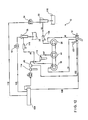
- FIG 12 there is disclosed a fluidic circuit and equipment diagram which discloses and illustrates still another primary feature characteristic of the resin or adhesive dispensing system 10 characteristic of the present invention. More particularly, it will be appreciated that in accordance with the arrangement and utilization of the particular components parts comprising the new and improved adhesive dispensing system 10, the various powered components of the system 10 are pneumatic. This enables the use of manufacturing plant air, which is readily available and plentiful as a source of power, and eliminates the use of hydraulic components which normally requires a substantial amount of components for a hydraulic powered resin or adhesive dispensing system and eliminates the need for electrically powered motor drive components which can sometimes have the potential to explode and are hazardous to use within plant environments.
- the resin or adhesive dispensing system 10 of the present invention is seen to comprise an air drive motor 44.
- Air drive motor 44 is operatively coupled to the activator metering pump 18 and the adhesive metering pump 20.
- trigger valve 100 of dispensing gun 12 is opened, an air signal through air signal conduit 102 is sent to air regulator 45.
- Pressurized air for the air signal is provided via dispensing gun 12 by air manifold 104 or an external pressurized air source through conduit 106.
- Adjusting the flow of adhesive can be accomplished by adjusting air regulator 45, with the adjustment reflected in the opening and closing of air regulator 45 caused by the air signal.
- air regulator 45 Upon receiving the air signal, air regulator 45 opens completely to allow pressurized air from air manifold 104 or an alternative exterior air source through conduit 107 to activate air drive motor 44. Air drive motor 44 in a simultaneous manner then drives activator metering pump 18 and adhesive metering pump 20.
- Activator metering pump 18 then pumps a proper amount of activator material for mixing with adhesive or resin material to dispensing gun 12 by activator conduit 14.
- Activator metering pump 18 is supplied with activator material through activator transfer conduit 40 by activator transfer pump 38.
- Activator transfer pump 38 draws its activator material supply from supply tank 36.
- the output of activator transfer pump 38 is regulated by air pressure controls 42 which control the amount of pressurized air through conduit 108 from air manifold 104 or an external pressurized air source to drive the activator transfer pump 38.
- Adhesive metering pump 20 acts simultaneous with activator metering pump 18.
- Adhesive metering pump 20 pumps a proper amount of PLEXIS methacrylate adhesive or suitable equivalent for mixing with activator material to dispensing gun 12 through adhesive conduit 16.
- Adhesive metering pump 20 is supplied with adhesive or resin material through adhesive transfer conduit 32 by adhesive transfer pump 30.
- Adhesive transfer pump 30, depending on the model of pump used, draws its supply from either a five-gallon or a fifty-five gallon container 110.
- the output of adhesive transfer pump 30 is regulated by air pressure controls 34 at a localized operator station. Air pressure controls 34 regulate the amount of pressurized air through air conduit 112 to drive adhesive transfer pump 30.
- Auxiliary items such as filter elements 114 and strainers 116 are provided for the filtration of adhesive or resin material, activator material and/or pressurized air before such material or air enters operating equipment of the adhesive or resin dispensing system.
- a new and improved resin or adhesive material dispensing system has been provided and disclosed.
- the new and improved resin or adhesive dispensing system enables the activator and adhesive metering pumps to be separately or independently driven by or from the air drive motor with varying output which is important for calibration, servicing, and maintenance operations as well as versatility during dispensing operations.
- the activator and adhesive metering pumps, as well as the air drive motor, are mounted upon laterally adjustable mounting brackets so as to facilitate the exchange or replacement of different sized sprocket members operatively mounted upon the rotary shafts of the metering pumps and the air drive motor whereby different mixture ratios of the activator material with respect to the resin or adhesive material may be readily and simply achieved; and the air drive motor is driven by means by compressed air readily available in the manufacturing plant or facility such that electrically or hydraulically powered motor drives are rendered unnecessary and are eliminated.
Landscapes
- Engineering & Computer Science (AREA)
- Mechanical Engineering (AREA)
- General Engineering & Computer Science (AREA)
- Chemical & Material Sciences (AREA)
- Chemical Kinetics & Catalysis (AREA)
- Coating Apparatus (AREA)
Abstract
Description
Claims (11)
- A two-component mixture dispensing system, comprising:a first metering pump for dispensing a first component of a two-component mixture;a second metering pump for dispensing a second component of said two-component mixture;an air drive motor for driving said first and second metering pumps;an air regulator operatively coupled to said air drive motor so as to vary the output of said air drive motor by regulating an air pressure to said air drive motor.
- A system according to Claim 1, further comprising:a source of high-pressure air comprising a pneumatic fluid supply conduit fluidically connecting said source of high-pressure air to said air regulator for supplying pneumatic air from said source of high-pressure air to said air drive motor.
- A system according to Claim 2, wherein said air regulator is disposed within said pneumatic fluid conduit so as to regulate an amount of high-pressure air driving said air drive motor by said high-pressure air transmitted by said source, said air drive motor operatively connected to said first and second metering pumps so as to, in turn, drive said first and second metering pumps when said air drive motor is operatively driven by said high-pressure air transmitted through said pneumatic fluid conduit such that an output of said first and second metering pumps is based on said regulated amount.
- A system according to Claim 2 or Claim 3, further comprising:a dispensing gun; anda pneumatic switch mounted upon said dispensing gun for opening and closing said pneumatic fluid supply conduit so as to terminate operation of said air drive motor as a result of activation of said air regulator where said air regulator is moved from an OPENED state to a CLOSED state, and to initiate operation of said air drive motor as a result of activation of said air regulator where said air regulator is moved from a CLOSED state to an OPEN state.
- A system according to any preceding claim, further comprising drive chains operatively interconnecting said air drive motor to said first and second metering pumps for directly driving both of said first and second metering pumps by said air drive motor and for driving each one of said first and second metering pumps by said air drive motor separately and independently with respect to the other one of said first and second metering pumps; wherein
a pair of axially spaced sprocket members are mounted upon said air drive motor;
a first sprocket member is mounted upon said first metering pump;
a second sprocket member is mounted upon said second metering pump; and
said drive chains comprise a first drive chain operatively interconnecting a first one of said pair of axially spaced sprocket members mounted upon said air drive motor and said first sprocket member mounted upon said first metering pump, and a second drive chain operatively interconnecting a second one of said pair of axially spaced sprocket members mounted upon said air drive motor and said second sprocket member mounted upon said second metering pump. - A system according to any preceding claim, wherein:said first and second metering pumps are mounted upon opposite lateral sides of said air drive motor.
- A system according to any preceding claim, further comprising:means for adjustably mounting at least one of said first and second metering pumps with respect to said air drive motor so as to accommodate different drive means for said at least one of said first and second metering pumps with respect to said air drive motor whereby different amounts of a first one of said first and second components of said two-component mixture, with respect to the second one of said first and second components of said two-component mixture, may be dispensed by said first and second metering pumps.
- A system according to Claim 7 as dependent upon Claim 5, wherein said means for adjustably mounting at least one of said first and second metering pumps with respect to said air drive motor to accommodate different said sprocket members as said drive means.
- A system as according to Claim 7 or 8, wherein said adjustable mounting means comprises:a support platform; andat least one mounting bracket, upon which said at least one of said first and second metering pumps is mounted, movably mounted upon said support platform.
- A system according to Claim 9, further comprising:at least one slot defined within said at least one mounting bracket; andat least one fastener disposed within said slot and engaged with said support platform for permitting said at least one mounting bracket to be moved to a selected position when said at least one fastener is disposed in a loosened state with respect to said support platform, and for fixing said at least one mounting bracket at said selected position when said at least one fastener is disposed in a tightened state with respect to said support platform.
- A system according to any preceding claim, wherein said air regulator is configured for controlling a speed of said air drive motor such that an output of said air drive motor can be varied for driving said first and second metering pumps.
Applications Claiming Priority (2)
| Application Number | Priority Date | Filing Date | Title |
|---|---|---|---|
| US09/969,356 US6607099B2 (en) | 1999-12-17 | 2001-10-02 | Air drive system |
| US969356 | 2001-10-02 |
Publications (2)
| Publication Number | Publication Date |
|---|---|
| EP1300189A2 true EP1300189A2 (en) | 2003-04-09 |
| EP1300189A3 EP1300189A3 (en) | 2004-05-19 |
Family
ID=25515466
Family Applications (1)
| Application Number | Title | Priority Date | Filing Date |
|---|---|---|---|
| EP02018972A Withdrawn EP1300189A3 (en) | 2001-10-02 | 2002-08-26 | Air drive system |
Country Status (2)
| Country | Link |
|---|---|
| US (1) | US6607099B2 (en) |
| EP (1) | EP1300189A3 (en) |
Cited By (1)
| Publication number | Priority date | Publication date | Assignee | Title |
|---|---|---|---|---|
| NL1023987C2 (en) * | 2003-07-24 | 2005-01-25 | Handelsmij D Bonsink B V | Device and method for manufacturing filler, and vehicle provided with such a device. |
Families Citing this family (2)
| Publication number | Priority date | Publication date | Assignee | Title |
|---|---|---|---|---|
| US20060027598A1 (en) * | 2004-05-21 | 2006-02-09 | Pepsico, Inc. | Integrated beverage and ice dispenser assembly |
| US10751748B1 (en) | 2017-07-19 | 2020-08-25 | 4 C's Spray Equipment Rental, LLC | Adhesive dispensing system and method |
Family Cites Families (8)
| Publication number | Priority date | Publication date | Assignee | Title |
|---|---|---|---|---|
| US3236419A (en) * | 1964-02-10 | 1966-02-22 | Continental Aviat & Eng Corp | Foam dispenser |
| US3818930A (en) * | 1973-04-20 | 1974-06-25 | Nordson Corp | Control system for an adhesive gun |
| US4516700A (en) * | 1982-03-31 | 1985-05-14 | Pyles Division | Hot melt anti-surge dispensing system |
| US4634024A (en) * | 1984-01-16 | 1987-01-06 | Technical Innovations, Inc. | Automatic resin dispensing apparatus |
| US4778631A (en) * | 1985-10-02 | 1988-10-18 | Nordson Corporation | Method and apparatus for foaming high viscosity polymer materials |
| US5388761A (en) * | 1993-10-01 | 1995-02-14 | Langeman; Gary D. | Plural component delivery system |
| IT235104Y1 (en) * | 1994-08-08 | 2000-03-31 | Bruno Moretti | PUMP DRIVING DEVICE IN A PLANT FOR POLYURETHANE FOAMING |
| US6321946B1 (en) * | 1999-12-17 | 2001-11-27 | Illinois Tool Works Inc. | Fusionmate two part adhesive dispensing system |
-
2001
- 2001-10-02 US US09/969,356 patent/US6607099B2/en not_active Expired - Fee Related
-
2002
- 2002-08-26 EP EP02018972A patent/EP1300189A3/en not_active Withdrawn
Cited By (2)
| Publication number | Priority date | Publication date | Assignee | Title |
|---|---|---|---|---|
| NL1023987C2 (en) * | 2003-07-24 | 2005-01-25 | Handelsmij D Bonsink B V | Device and method for manufacturing filler, and vehicle provided with such a device. |
| WO2005009600A1 (en) * | 2003-07-24 | 2005-02-03 | Handelsmaatschappij D.Bonsink B.V. | Device and method for manufacturing filler, and vehicle provided with such a device |
Also Published As
| Publication number | Publication date |
|---|---|
| EP1300189A3 (en) | 2004-05-19 |
| US6607099B2 (en) | 2003-08-19 |
| US20020079328A1 (en) | 2002-06-27 |
Similar Documents
| Publication | Publication Date | Title |
|---|---|---|
| US4278205A (en) | Constant flow rate fluid supply device, particularly for a spray gun | |
| JP5775575B2 (en) | Dual pump type fluid mixing device with adjustable motor position | |
| US4090262A (en) | Mixing and proportioning apparatus for multi-component plastics materials | |
| CN102639873B (en) | For the system and method for control linear pumping system | |
| AU3540995A (en) | Modular dispenser for multiple fluids | |
| EP2366297B1 (en) | Cloth bonding apparatus | |
| US6607099B2 (en) | Air drive system | |
| KR20160034342A (en) | Pump changeover algorithm for spray system | |
| US6321946B1 (en) | Fusionmate two part adhesive dispensing system | |
| CN116213565A (en) | Automatic riveting equipment for washing machine box body and using method thereof | |
| US20080078782A1 (en) | Rotary pump plural component applicator | |
| FI75214B (en) | PNEUMATIC STYRD TRYCKOMVANDLARE FOER DRIFT AV ETT HYDRAULISKT ARBETSORGAN. | |
| KR101905868B1 (en) | Selection type painting device having multi supply lines | |
| US5634574A (en) | Bakery mix dispenser | |
| CA2222927C (en) | Apparatus and method for dispensing fluid material | |
| CA2155066C (en) | Dispensing apparatus | |
| EP2459304B1 (en) | Variable flow control using linear pumps | |
| CA2597357A1 (en) | Foaming method and apparatus therefor | |
| CN107234035B (en) | A kind of functional steel plate surface automation glue sprayer | |
| EP2255955B1 (en) | Cloth bonding apparatus | |
| EP2233277A1 (en) | Cloth bonding apparatus | |
| CN220636739U (en) | Solder paste dispensing equipment | |
| JP3701181B2 (en) | Multi-component mixed pressure feeder | |
| KR101771072B1 (en) | Hybrid vehicle for painting line | |
| JPH08131921A (en) | Liquid mixing and discharging device |
Legal Events
| Date | Code | Title | Description |
|---|---|---|---|
| PUAI | Public reference made under article 153(3) epc to a published international application that has entered the european phase |
Free format text: ORIGINAL CODE: 0009012 |
|
| AK | Designated contracting states |
Kind code of ref document: A2 Designated state(s): AT BE BG CH CY CZ DE DK EE ES FI FR GB GR IE IT LI LU MC NL PT SE SK TR Designated state(s): AT BE BG CH CY CZ DE DK EE ES FI FR GB GR IE IT LI LU MC NL PT SE SK TR |
|
| AX | Request for extension of the european patent |
Extension state: AL LT LV MK RO SI |
|
| PUAL | Search report despatched |
Free format text: ORIGINAL CODE: 0009013 |
|
| AK | Designated contracting states |
Kind code of ref document: A3 Designated state(s): AT BE BG CH CY CZ DE DK EE ES FI FR GB GR IE IT LI LU MC NL PT SE SK TR |
|
| AX | Request for extension of the european patent |
Extension state: AL LT LV MK RO SI |
|
| 17P | Request for examination filed |
Effective date: 20041111 |
|
| AKX | Designation fees paid |
Designated state(s): AT BE BG CH CY CZ DE DK EE ES FI FR GB GR IE IT LI LU MC NL PT SE SK TR |
|
| GRAP | Despatch of communication of intention to grant a patent |
Free format text: ORIGINAL CODE: EPIDOSNIGR1 |
|
| STAA | Information on the status of an ep patent application or granted ep patent |
Free format text: STATUS: THE APPLICATION IS DEEMED TO BE WITHDRAWN |
|
| 18D | Application deemed to be withdrawn |
Effective date: 20070908 |