EP1300170B1 - Verbessertes Gerät und Methode der Entfernung einer Nadel von einer Spritze - Google Patents
Verbessertes Gerät und Methode der Entfernung einer Nadel von einer Spritze Download PDFInfo
- Publication number
- EP1300170B1 EP1300170B1 EP02256917A EP02256917A EP1300170B1 EP 1300170 B1 EP1300170 B1 EP 1300170B1 EP 02256917 A EP02256917 A EP 02256917A EP 02256917 A EP02256917 A EP 02256917A EP 1300170 B1 EP1300170 B1 EP 1300170B1
- Authority
- EP
- European Patent Office
- Prior art keywords
- needle
- needle cartridge
- cartridge
- housing
- contact
- Prior art date
- Legal status (The legal status is an assumption and is not a legal conclusion. Google has not performed a legal analysis and makes no representation as to the accuracy of the status listed.)
- Expired - Lifetime
Links
- 238000000034 method Methods 0.000 title claims abstract description 8
- 230000004044 response Effects 0.000 claims description 9
- 239000002699 waste material Substances 0.000 claims description 9
- 239000004020 conductor Substances 0.000 claims description 3
- 238000002844 melting Methods 0.000 abstract description 9
- 230000008018 melting Effects 0.000 abstract description 8
- 244000005700 microbiome Species 0.000 abstract description 6
- 208000015181 infectious disease Diseases 0.000 abstract description 5
- 230000001954 sterilising effect Effects 0.000 abstract description 3
- 241000894006 Bacteria Species 0.000 abstract description 2
- 240000004808 Saccharomyces cerevisiae Species 0.000 abstract description 2
- 241000700605 Viruses Species 0.000 abstract description 2
- 238000010438 heat treatment Methods 0.000 abstract description 2
- 239000000463 material Substances 0.000 description 12
- 239000002184 metal Substances 0.000 description 9
- 239000004033 plastic Substances 0.000 description 6
- 230000006835 compression Effects 0.000 description 5
- 238000007906 compression Methods 0.000 description 5
- 230000009970 fire resistant effect Effects 0.000 description 5
- 230000002458 infectious effect Effects 0.000 description 3
- 230000013011 mating Effects 0.000 description 3
- 230000004048 modification Effects 0.000 description 3
- 238000012986 modification Methods 0.000 description 3
- 229910000831 Steel Inorganic materials 0.000 description 2
- 230000000994 depressogenic effect Effects 0.000 description 2
- 238000010008 shearing Methods 0.000 description 2
- 239000010959 steel Substances 0.000 description 2
- 208000030507 AIDS Diseases 0.000 description 1
- 208000035473 Communicable disease Diseases 0.000 description 1
- 239000004593 Epoxy Substances 0.000 description 1
- 229920000784 Nomex Polymers 0.000 description 1
- 238000005452 bending Methods 0.000 description 1
- 230000000903 blocking effect Effects 0.000 description 1
- 238000004140 cleaning Methods 0.000 description 1
- 239000011248 coating agent Substances 0.000 description 1
- 238000000576 coating method Methods 0.000 description 1
- 238000010586 diagram Methods 0.000 description 1
- 201000010099 disease Diseases 0.000 description 1
- 208000037265 diseases, disorders, signs and symptoms Diseases 0.000 description 1
- 239000000835 fiber Substances 0.000 description 1
- 239000003063 flame retardant Substances 0.000 description 1
- 239000012530 fluid Substances 0.000 description 1
- 208000002672 hepatitis B Diseases 0.000 description 1
- 230000000415 inactivating effect Effects 0.000 description 1
- 238000003780 insertion Methods 0.000 description 1
- 230000037431 insertion Effects 0.000 description 1
- 238000002955 isolation Methods 0.000 description 1
- 239000004763 nomex Substances 0.000 description 1
- 238000003825 pressing Methods 0.000 description 1
- 230000002035 prolonged effect Effects 0.000 description 1
- 230000000717 retained effect Effects 0.000 description 1
- 229910001220 stainless steel Inorganic materials 0.000 description 1
- 239000010935 stainless steel Substances 0.000 description 1
Images


Classifications
-
- A—HUMAN NECESSITIES
- A61—MEDICAL OR VETERINARY SCIENCE; HYGIENE
- A61M—DEVICES FOR INTRODUCING MEDIA INTO, OR ONTO, THE BODY; DEVICES FOR TRANSDUCING BODY MEDIA OR FOR TAKING MEDIA FROM THE BODY; DEVICES FOR PRODUCING OR ENDING SLEEP OR STUPOR
- A61M5/00—Devices for bringing media into the body in a subcutaneous, intra-vascular or intramuscular way; Accessories therefor, e.g. filling or cleaning devices, arm-rests
- A61M5/178—Syringes
- A61M5/31—Details
- A61M5/32—Needles; Details of needles pertaining to their connection with syringe or hub; Accessories for bringing the needle into, or holding the needle on, the body; Devices for protection of needles
- A61M5/3205—Apparatus for removing or disposing of used needles or syringes, e.g. containers; Means for protection against accidental injuries from used needles
- A61M5/3278—Apparatus for destroying used needles or syringes
-
- A—HUMAN NECESSITIES
- A61—MEDICAL OR VETERINARY SCIENCE; HYGIENE
- A61M—DEVICES FOR INTRODUCING MEDIA INTO, OR ONTO, THE BODY; DEVICES FOR TRANSDUCING BODY MEDIA OR FOR TAKING MEDIA FROM THE BODY; DEVICES FOR PRODUCING OR ENDING SLEEP OR STUPOR
- A61M5/00—Devices for bringing media into the body in a subcutaneous, intra-vascular or intramuscular way; Accessories therefor, e.g. filling or cleaning devices, arm-rests
- A61M5/178—Syringes
- A61M5/31—Details
- A61M5/32—Needles; Details of needles pertaining to their connection with syringe or hub; Accessories for bringing the needle into, or holding the needle on, the body; Devices for protection of needles
- A61M5/3205—Apparatus for removing or disposing of used needles or syringes, e.g. containers; Means for protection against accidental injuries from used needles
- A61M5/3278—Apparatus for destroying used needles or syringes
- A61M2005/3283—Apparatus for destroying used needles or syringes using electric current between electrodes
-
- Y—GENERAL TAGGING OF NEW TECHNOLOGICAL DEVELOPMENTS; GENERAL TAGGING OF CROSS-SECTIONAL TECHNOLOGIES SPANNING OVER SEVERAL SECTIONS OF THE IPC; TECHNICAL SUBJECTS COVERED BY FORMER USPC CROSS-REFERENCE ART COLLECTIONS [XRACs] AND DIGESTS
- Y10—TECHNICAL SUBJECTS COVERED BY FORMER USPC
- Y10S—TECHNICAL SUBJECTS COVERED BY FORMER USPC CROSS-REFERENCE ART COLLECTIONS [XRACs] AND DIGESTS
- Y10S83/00—Cutting
- Y10S83/929—Particular nature of work or product
- Y10S83/944—Syringe needle
Definitions
- This invention relates to a method and apparatus for destroying the needle portion of a syringe.
- the present invention relates to a method and apparatus that heats, sterilizes and severs the needle portion of a syringe after the needle has been used on a patient.
- U.S. Patent No. 4,877,934 discloses a needle destroying apparatus using converging electrodes to destroy the needle.
- the burnt needle tends to bend and lose contact with an electrode during operation, and the burnt needles tend to collect on the bottom electrode of that apparatus.
- U.S. Patent No. 5,736,706 discloses apparatus for removing syringe needles using a needle carriage that must be rotated from a loading position to a cut-off position to sever and remove the needle from the syringe.
- the document GB-A-2300339 is acknowledged as prior art to the present invention. It discloses an apparatus for disposing of hypodermic needles comprising a main housing and a disposable cartridge releasably secured to the housing.
- What is needed is an improved needle removal apparatus that is easy to operate and will reliably remove and contain the needle without risk of sticking. What is further needed is an apparatus that can be used in a clinical environment for long periods of time without requiring disassembly for servicing or cleaning.
- the present invention is an apparatus and method for destroying a syringe needle by heating the needle to the melting temperature and simultaneously severing the needle from the plastic syringe. More particularly, the invention comprises a housing and a needle cartridge that receives a needle in a loading position. When a needle is inserted into the housing, the needle cartridge is retracted to a cut-off position. At the cutoff position, two opposing contact surfaces pinch the needle and electrically connect the needle to an electrical power source such as a battery. Current flows through the contact surfaces and the needle, thereby melting a portion of the needle.
- an electrical power source such as a battery
- the apparatus preferably includes a layer of fire-retardant material that the needle penetrates to engage the needle cartridge, to prevent sparks from escaping the apparatus as the needle is melted and severed.
- the needle cartridge is removable from the housing for suitable disposal after destroying a predetermined number of needles.
- the severed needle portions remain within the needle cartridge during and after such removal, and thus are not exposed to contact by the waste handlers.
- the replacement needle cartridge includes new contact surfaces for pinching and melting needles, so that the contact surfaces should not require servicing during normal operation.
- an object of the present invention to provide a safe, low cost, efficient and easy-to-use device for sterilizing and destroying the metal needle of a hypodermic syringe, thereby killing any infectious microorganism that may be present in or on the needle.
- an apparatus for removing the needle portion of a syringe comprising a housing and a needle cartridge as stated above.
- the present invention is a method and apparatus for removing and safely discarding the needle portion of a hypodermic syringe.
- the present invention is, in part, an apparatus that is capable of simultaneously sterilizing and removing the needle portion of a hypodermic syringe and hereby eliminating the risk of infection by a microorganism that may be present in or on the needle.
- a portion of the needle adjacent the plastic barrel of the syringe is heated to a temperature of at least 1,750° C. This temperature is capable of inactivating any virus, bacteria, yeast, or other microorganism remaining on or within the needle.
- the needle metal is sheared at the melted region so that the needle is removed from the remaining portion of the syringe.
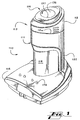
- 110 denotes generally a needle removal and disposal apparatus according to the present invention, and including a housing 111 and a needle cartridge 112 removably received within the open upper end 111a of the housing.
- the housing and cartridge are made of any suitable material such as metal, plastic or the like, so long as that material is capable of maintaining structural integrity if exposed to sparks caused by the melting needle as described below.
- the needle cartridge 112 is made so that it can be withdrawn from the open upper end of the housing 111 and disposed of at the end of its useful lifetime. Because the needle cartridge of the disclosed embodiment is meant to be disposable in normal use, it is preferred that the materials of that cartridge be chosen with the cost of replacement in mind.
- the housing preferably includes a base 116 having a substantially flat bottom surface, thus allowing the apparatus to be placed upright on a table, counter top, or other similar surface.
- the base also may be adapted for mounting on a wall.
- the housing has a front wall 118, a rear wall 120, and side walls 122 defining a generally hollow interior 126 open at the upper end 111a to receive the needle cartridge 112, which is removably received within the hollow interior of the housing.
- the needle cartridge 112 includes a collar 113 that rests on the upper end of the housing 111, and a needle removal unit 114 retained within the collar for vertical movement relative to the collar and the housing.
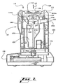
- the needle removal unit is located within the housing 111 on top of a compression return spring 140, Fig. 2.
- a waste compartment 128 generally comprising a hollow chamber, is located within a lower portion of the needle removal assembly. The upper portion of the waste compartment is open to receive cut-off needles, as described below.
- a dish 136 for receiving a needle to be removed is provided in the upper end 134 of the needle removal assembly 114.
- the dish 136 is in the shape of a cone, having a wide upper end to accept the needle end of a hypodermic syringe and tapering down to a small opening 137, Fig. 6, dimensioned to receive only the metal needle portion of a hypodermic syringe.
- a needle contact and cutting assembly 140 Secured within the needle removal unit 114, immediately below the opening 137 at the lower end of the of the dish 136, is a needle contact and cutting assembly 140 best seen in Figs. 4 and 5. That assembly has a pair of contact blades 142 and 144, each being formed of electrically conductive material such as steel. Each blade 142 and 144 is mounted at first ends of paired L-shaped levers forming yokes 146 and 148. The yokes are pivotably supported by axles 150 and 152, each mounted within the needle removal unit 114 so as to move up and down with the needle removal unit.
- the second ends 154 and 156 of the yokes 146 and 148 are engaged by fingers 154 and 156 of the yoke key 158, located below the yokes.
- the yoke key 158 is within the needle removal unit 114 but has an extension 159 protruding through a slot in the side of that unit to fit within a mating recess 160 formed on the inside wall of the collar 113.
- the yoke key 158 thus remains stationary and pivots the yokes 146 and 148 on their axes 150 and 152 when the needle removal unit 114 moves within the collar.
- Sharpened inner edges 162 and 164 on the contact blades 142 and 144 extend directly under and on opposite sides of the opening 137 in the dish 136, and those inner edges may be notched at the point of contact with a needle placed between the contact blades.
- Electrical connector tabs 165a, 165b on the ends of the contact blades opposite the inner edges are electrically connected by wires 166a, 166b (Fig. 7) to a power connector 167 located on a lower portion of the needle cartridge 112 so as to contact mating terminals of a connector 168 within the housing 111.
- the connectors 167 and 168 are housed within the power connection 170, Fig. 2, for physical isolation from other components when the needle cartridge is inserted within the upper end of the housing.
- the power connector 168 is connected to a power source such as the rechargeable battery 172 located in the base 116 of the housing 111.
- the battery 172 is charged by plug connection to an external transformer 174 through a control circuit 176 within the base.
- a circuit breaker is incorporated in the electric circuit including the battery and the control blades. The circuit breaker will trip to open the power circuit in response to a current exceeding a normal amount for the brief duration required to melt the needle of a syringe. Such excessive current might be caused, for example, by insertion through the opening 137 of a metal object more durable than the conventional needle.
- a reset control for the circuit breaker is located on the base of the housing.
- a fuse in the power circuit to the power connector provides added protection against prolonged excess current.
- the control circuit 176 also connects to a fusible link 181 in the needle removal unit 112, by a second pair of mating connectors 183 on a lower portion of the needle cartridge and within the housing 111.
- the fusible link 181 is selected to blow in response to a relatively low-power signal current, which the fusible link receives from the control circuit 176 when a fresh needle cartridge is inserted into the housing 111.
- the momentary current flow through the circuit including the fusible link operates a logic circuit within the control circuit, signifying to that logic circuit that the needle removal apparatus 110 has a fresh needle cartridge, whereupon the logic circuit resets a counter within the control circuit that keeps track of the number of times the previous needle cartridge drew a needle-melting current from the battery. Because the control circuit looks for an intact fusible link 181 when a needle cartridge is installed, the apparatus 110 will not operate if a needle cartridge is removed and later reinstalled within the apparatus.
- the control circuit 176 is connected to operate four LEDs 178 on the base 116. Those LEDs indicate functions of the control circuit, which by way of example are: a green LED, indicating the unit is charged and ready to function; a yellow LED indicating the battery 172 is low and requires connection to the charger; a red LED indicating the apparatus is turned off and will not cut needles (for example, because the battery is too low or the cartridge 117 is full and needs replacing); and an orange LED that commences flashing at a predetermined number of cuts, indicating the needle cartridge is nearing capacity. The orange LED will stop flashing and the red LED turns on when the counter of the control circuit 176 registers maximum capacity. When the needle cartridge 112 is replaced with a fresh cartridge containing an intact fusible link 181, the control circuit turns off the red and orange LEDs and turns on the green LED, indicating the unit is again ready to cut needles.
- a green LED indicating the unit is charged and ready to function
- a yellow LED indicating the battery 172 is low and requires connection to the
- a layer of fire-resistant material 180 (Figs. 4 and 5) easily penetrated by a needle is located between the opening 137 of the dish 136 and the first contact blade 142.
- the material 24 preferably is woven so as to be repeatedly penetrable by needles without cutting or otherwise damaging the material.
- a fire-resistant fiber such as Nomex® or the like is used for the material 24, in a preferred embodiment of the invention.
- a hypodermic syringe is inserted, needle first, into the dish 136 in the needle cartridge with the needle cartridge in the loading position as shown in Figs. 2 and 5.
- the needle 182 is fully inserted through the opening 137 at the bottom of the dish until the neck and shoulder portions of the syringe contact the bottom of the dish 136 and can be inserted no further.
- the hypodermic needle 182 When the hypodermic needle 182 is fully inserted, the needle penetrates the layer of material 180 to extend beyond and between the sharpened inner edges 162 and 164 of the first and second contact blades 142 and 144.
- the syringe With the needle remaining fully inserted, the syringe is pushed down against the dish 136 in order to depress the needle removal unit 114 into the cut-off position.
- the introduction of downward force exerted on the needle removal unit 114 overcomes the resistance force of the compression spring 140, so that the needle removal unit moves downwardly within the collar 113 and housing 111.
- the yoke key 158 pivots the yokes 146 and 148 on the axles 150 and 152, causing the inner edges 162 and 164 of the contact blades to engage opposite sides of the needle 182 immediately below the fire-resistant layer 180 beneath the bottom of the dish 136.
- the axle 152 of the yoke 148 is mounted slightly below the corresponding axle 150 of the other yoke 146, as best seen in Fig. 5.
- the edge 164 of the contact blade 144 contacts the needle 182 at a small offset from the edge 162 of the other blade 142.
- the sharpened edges of the first and second contact blades pinch the melted needle between the contact blades, shearing the melted needle at the pinch point so that the severed portion of the needle falls downwardly into the waste compartment 128, Fig. 2.
- the baffle plate 179 in the needle cartridge helps guide the severed needles into that compartment.
- the electrical circuit is interrupted when the needle is melted and severed at the pinch point, and the hypodermic syringe may then be removed from the dish 136 and placed elsewhere for appropriate disposal. Removing the syringe from the dish 136 removes the downward force on the needle removal unit 114 so that the compression spring 140 returns the needle removal unit to the loading position.
- the diameter of the opening 137 in the dish 136 can be sized to accept any conventional gauge stainless steel needles therethrough while blocking entry of the plastic barrel portion of the syringe.
- the remaining stump of the melted and severed needle typically extends only about 1/8 inch below the barrel portion and lacks a sharp point, thus presenting no needle-sticking hazard.
- the high temperature reached to melt the steel needle should render harmless any infectious organisms that may have been present on or within the needle.
- the layer of fire-resistant material 180 prevents sparks or flames from entering the dish 136 through the opening 137 as the contact blades engage the needle.
- the needle cartridge 112 and its components are intended to be disposable upon removal from the housing.
- the needle cartridge 112 thus will be periodically removed for disposal and replaced with a fresh cartridge.
- the severed needles remain enclosed within the removed needle cartridge, as that cartridge is disposed in an appropriate manner.
- the blades must be replaced after a number of needle-removal operations so as to maintain effective operation of the apparatus.
- the blades are replaced by removing and disposing of the entire needle cartridge 112, which also disposes of the removed needles accumulated in the waste compartment 128.
- the counter within the control circuit 176 increments a count in response to each time the contact blades establish current flow through a needle.
- the switch 177 associated with the control is opened so as to prevent further operation of the apparatus until the needle cartridge is replaced.
- the control circuit at that time illuminates the red LED on the base 116, indicating that the apparatus will not operate until the needle cartridge is replaced. Merely removing and reinstalling the used needle cartridge will not reset the counter or reactivate the apparatus, because the fusible link 181 in that needle cartridge now lacks an intact fusible link 181 required to tell the control circuit that a fresh needle cartridge has been installed.
- the apparatus is inactivated in response to 200 needle removals.
- the orange LED commences flashing when 180 needle removals occur, indicating the needle cartridge will soon require replacement. It should be understood that these counts are not critical aspects of the invention.
- Figs. 8 and 9 show an alternative embodiment of apparatus according to the present invention, in which the needle contact and cutting assembly 210 uses a single movable contact blade 212 and a fixed contact blade 214 instead of the first and second movable blades in the previously-described embodiment.
- the fixed contact blade 214 is secured within the needle cartridge, immediately below the opening 137 at the bottom of the dish 136.
- the fixed contact blade 214 is formed of electrically conductive material and has an annular shape surrounding the opening 137.
- a sharpened inner edge 216 of the fixed contact blade extends directly under the smaller opening 137, and a tab 218 on the fixed contact blade is electrically connected by a wire to a first terminal of the battery or other suitable power supply as previously described.
- the layer of fire-resistant material 180 is disposed between the opening 137 of the dish 136 and the fixed contact blade 214.
- the movable contact blade 212 is located at one end of a yoke 224 pivotably supported on the axle 226. That movable contact blade is connected by a wire to a second terminal of the battery or other power supply and has an outer sharpened edge 220 located immediately below the fixed contact blade 214.
- the other end of the yoke 224 has a finger 248 extending for engagement with a fixed element of the housing within which the needle cartridge containing the assembly 210 is received, in the manner of the extension 159 of the yoke key 158 in the embodiment described above.
- the finger 248 contacts a fixed element of the housing, pivoting the yoke 224 on the axle 226 and causing the sharpened inner edge 220 of the second contact blade 212 to engage the needle and displace the needle into contact with the sharpened inner edge 216 of the fixed contact blade 214.
- an electrical circuit is formed including the first and second contact blades and the needle portion between the contact blades, and an electrical current flows through the circuit to melt that portion of the needle.
- the sharpened edges of the first and second contact blades pinch the melted needle between the contact blades, shearing the needle at the pinched point so that the severed portion of the needle falls downwardly into the waste compartment as previously described.
Landscapes
- Health & Medical Sciences (AREA)
- Engineering & Computer Science (AREA)
- Heart & Thoracic Surgery (AREA)
- Vascular Medicine (AREA)
- Anesthesiology (AREA)
- Biomedical Technology (AREA)
- Environmental & Geological Engineering (AREA)
- Hematology (AREA)
- Life Sciences & Earth Sciences (AREA)
- Animal Behavior & Ethology (AREA)
- General Health & Medical Sciences (AREA)
- Public Health (AREA)
- Veterinary Medicine (AREA)
- Infusion, Injection, And Reservoir Apparatuses (AREA)
- Accommodation For Nursing Or Treatment Tables (AREA)
Claims (24)
- Nadelpatrone für eine Vorrichtung zur Entfernung eines Nadelteils einer Spritze, wobei die Nadelpatrone aufweist:wobei die Kontaktelemente (162, 163) in einander gegenüberstehender Zuordnung und, ebenso wie der zweite Teil, in der Ladestellung entlang des Eintrittswegs in einer vorbestimmten Ausrichtung angeordnet sind;einen ersten Teil (115) zur Aufnahme in stationärer Zuordnung zu dem Gehäuse (111) der Vorrichtung, und einen zweiten Teil (114), der wahlweise zwischen einer Ladestellung und einer Abschneidestellung relativ zu dem ersten Teil und zu dem Gehäuse (111) bewegbar ist;eine Aufnahmeöffnung (136, 137), die dem zweiten Teil (114) zur Aufnahme eines Nadelteils einer Spritze entlang eines vorherbestimmten Eintrittswegs unter Vermeidung des Eintritts eines Zylinderteils, von dem aus sich der Nadelteil erstreckt, zugeordnet ist;ein Paar von Kontaktelementen (162, 164), die der Nadelpatrone (112) auf einer Seite der Aufnahmeöffnung (136, 137) zugeordnet sind;
elektrische Leitungen, die sich von den Kontaktelementen (162,164) aus zu einer Verbindung zur Herstellung eines elektrischen Kontakts mit einer Stromquelle erstrecken, die dem Gehäuse (111) zugeordnet ist, in dem die Nadelpatrone (112) aufgenommen werden soll;
wobei die Nadelpatrone außerdem Mittel (146, 148, 154, 156, 159, 160) aufweist, die auf eine Bewegung des zweiten Teils der Nadelpatrone (112) in die Abschneidestellung ansprechen, um wenigstens ein Kontaktelement (162, 164) in Kontakt mit einer Nadel zu drücken, die den Eintrittsweg derart besetzt, dass die Kontaktelemente (162, 164) einen Stromfluss durch einen Nadelteil (112) bewirken, der groß genug ist, um den Nadelteil zu schmelzen,
woraufhin die Kontaktelemente (162, 164) die Nadel von dem Zylinderteil der Spritze trennen. - Nadelpatrone (112) nach Anspruch 1, wobei die Kontaktelemente (162, 164) entlang des Eintrittswegs der Nadel um einen derartigen Abstand gegeneinander versetzt sind, dass der Strom entlang dieses Abstands durch die Nadel fließt.
- Nadelpatrone nach Anspruch 1 oder 2, die außerdem folgende Teile aufweist:wobei die Stelleinrichtung (140) dieses wenigstens eine Kontaktelement (162, 164) abhängig von der Bewegung des zweiten Teils der Abschneidestellung gegen den Eintrittspfad der Nadel bewegt.eine Stelleinrichtung (140), die dem wenigstens einen Kontaktelement (162,164) in dem zweiten Teil der Nadelpatrone (112) zugeordnet ist und ein Stellglied aufweist, das mit dem ersten Teil der Nadelpatrone (112) in Eingriff steht;
- Nadelpatrone nach Anspruch 3, bei der beide Kontaktelemente (162, 164) relativ zu dem Nadeleintrittspfad in Reaktion auf die Stelleinrichtung (140) bewegbar sind.
- Nadelpatrone nach Anspruch 3 oder 4, bei der jedes Kontaktelement (162, 164) auf einem besonderen Hebel (146, 148) angeordnet ist; und
jeder dieser Hebel (146, 148) abhängig von der Stelleinrichtung (140) derart bewegbar ist, dass sich beide Kontaktelemente (162, 164) relativ zu dem Eintrittspfad der Nadel bewegen. - Nadelpatrone nach irgendeinem der Ansprüche 1 bis 5, die weiter folgende Teile aufweist:ein Speicherelement, das einen ersten Zustand aufweist, der einem Nichtbetriebszustand der Nadelpatrone (112) entspricht, und das in einen zweiten Zustand überzuwechseln vermag, bei dem die Nadelpatrone in Betrieb ist; undMittel, die den Zustand des Speicherelements zu einem Steuerungselement (176) übertragen, das dem Gehäuse (111) zugeordnet ist, in dem die Nadelpatrone (112) aufgenommen ist.
- Nadelpatrone (112) nach Anspruch 6, bei der das Speicherelement ein schmelzbares Zwischenstück (181) in der Nadelpatrone (112) und Schaltungsmittel aufweist, die dieses schmelzbare Zwischenstück mit Steuerungsmitteln (176) verbinden können, die dem Gehäuse zugeordnet sind, in dem die Nadelpatrone aufgenommen ist.
- Vorrichtung zur Entfernung des Nadelteils an einer Spritze, wobei die Vorrichtung folgende Teile aufweist:ein Gehäuse (111); undeine Nadelpatrone (112) gemäß irgendeinem der Ansprüche 1 bis 7.
- Vorrichtung nach Anspruch 8, bei der sich die ersten und die zweiten Kontaktflächen (162, 164) bewegen, um einen Teil der Nadel abzutrennen, wenn die Nadelpatrone (112) in die Abschneidestellung bewegt wird.
- Vorrichtung nach Anspruch 9, die weiter einen Abfallraum (128) aufweist, der innerhalb der Nadelpatrone (112) angeordnet ist und den abgetrennten Teil der Nadel aufnimmt, wobei der Abfallraum (128) einen oberen Teil mit einer Öffnung aufweist, die allgemein zwischen den Kontaktflächen (162, 164) angeordnet ist.
- Vorrichtung nach irgendeinem der Ansprüche 8 bis 10, die außerdem ein elektrisches Netzteil (172) aufweist, das mit den Kontaktflächen (162, 164) verbunden ist und das genügend Strom liefern kann, um einen Teil der Nadel so zu schmelzen, wenn die Nadelpatrone (112) in der Abschneidestellung ist, die Kontaktflächen (162, 164) den geschmolzenen Teil abtrennen können.
- Vorrichtung nach irgendeinem der Ansprüche 8 bis 11, die weiter eine Feder (140) aufweist, die dem Gehäuse (111) zugeordnet ist und mit diesem zusammenwirkt und die Nadelpatrone (112) bei Abwesenheit einer äußeren auf die Nadelpatrone (112) einwirkenden Kraft in die Ladestellung so drückt, dass eine von außen und gegen die Nadelpatrone (112) ausgeübte Kraft die Feder (140) zusammendrückt und bewirkt, dass die Nadelpatrone (112) von der Ladestellung in die Abschneidestellung bewegt wird.
- Vorrichtung nach Anspruch 12, bei der die Nadelpatrone außerdem folgende Teile aufweist:Ein flammhemmendes Bauteil (180), das zwischen der Aufnahmeöffnung (136, 137) und den Kontaktflächen (162, 164) derart angeordnet ist, dass Funken daran gehindert werden, aus der Aufnahmeöffnung (136, 137) auszutreten, wenn die Nadel geschmolzen und von dem Zylinderteil abgetrennt wird.
- Vorrichtung nach irgendeinem der Ansprüche 8 bis 13, bei der die Kontaktflächen (162, 164) entlang dem Eintrittspfad der Nadel derart um einen Abstand gegeneinander versetzt sind, dass der Strom entlang dieses Abstands durch die Nadel fließt.
- Vorrichtung nach irgendeinem der Ansprüche 8 bis 14, bei dem
das Gehäuse (111) zur Aufnahme der Nadelpatrone (112) innerhalb des Gehäuses (111) am oberen Ende offen ist;
dass die Nadelaufnahmeöffnung (136, 137) an einem oberen Ende der Nadelpatrone (112) so angeordnet ist, dass sie die Nadeln entlang einem im wesentlichen vertikalen Eingangspfad einschließlich der Aufnahmeöffnungen (136, 137) aufnehmen kann; und
dass die Nadelpatrone (112) von einer Ladestellung entlang einem im wesentlichen vertikalen Weg in die Abschneidestellung so bewegbar ist, dass die Nadeln in die Aufnahmeöffnung (136, 137) ohne Rücksicht auf ihre Winkelstellung um den Eintrittspfad eingeführt werden können. - Vorrichtung nach in irgendeinem der Ansprüche 8 bis 15, bei der die Quelle für den elektrischen Strom (172) in dem Gehäuse (111) angeordnet ist, wobei die Vorrichtung ferner aufweist:eine Steuerungseinrichtung, die auf die elektrische Schaltung anspricht und zählt, wie oft durch die Nadelpatrone (112) eine Nadel entfernt wurde.
- Vorrichtung nach Anspruch 16, die weiter folgende Teile enthält:Mittel (176), die auf eine vorherbestimmte Anzahl von abgezählten Nadelentfernungen einer Nadelpatrone (112) ansprechen und die Vorrichtung abstellen, bis die Nadelpatrone (12) ausgewechselt ist.
- Vorrichtung nach Anspruch 16 oder 17, bei der
die Nadelpatrone ein Speicherelement umfasst, das einen ersten Zustand aufweist, der den nicht in Betrieb befindlichen Zustand anzeigt, und das in einen zweiten Zustand überwechseln kann, wobei dieses auf das Einsetzen der Nadelpatrone in das Gehäuse (11) anspricht. - Vorrichtung nach Anspruch 18, bei der das Steuerungselement (176) auf den zweiten Zustand des Speicherelements anspricht und den Betrieb der Vorrichtung abschaltet, wenn eine Nadelpatrone (112) dann, wenn sich das Speicherelement in dem zweiten Zustand befindet, in das Gehäuse (111) eingesetzt wird.
- Vorrichtung nach Anspruch 18 oder 19, bei der das Steuerungselement (176) auf den ersten Zustand des Speicherelements in einer in dem Gehäuse eingesetzten Nadelpatrone anspricht, um den Zustand dieses Speicherelements in den zweiten Zustand so umzuschalten, dass die Nadelpatrone (112) danach als gebraucht identifizierbar ist.
- Vorrichtung nach Anspruch 20, bei der das Speicherelement ein schmelzbares Zwischenstück (181) in der Nadelpatrone (112) sowie Schaltungsmittel aufweist, die dieses schmelzbare Zwischenstück mit der Steuerungseinrichtung (176) verbinden, wenn die Nadelpatrone (112) in das Gehäuse eingesetzt wird.
- Vorrichtung nach Anspruch 17, bei der die Nadelpatrone (112) ein Speicherelement einschließt, das einen ersten Zustand aufweist, der einer nicht in Gebrauch befindlichen Arbeitsbedingung entspricht und der in einen zweiten Zustand umschalten kann, der einer in Gebrauch befindlichen Arbeitsbedingung entspricht; und
dass das Steuerungsmittel (176) auf den ersten Zustand des Speicherelements in einer in einem Gehäuse eingesetzten Nadelpatrone anspricht, um die Zähleinrichtung derart zurückzustellen, dass das Arbeiten mit dieser Nadelpatrone möglicht ist, und um den Zustand des Speicherelements in den zweiten Zustand derart umzuschalten, dass die Nadelpatrone (112) nicht länger ungenutzt ist. - Verfahren zur Entfernung eines Nadelteils an einer Spritze, wobei das Verfahren folgende Schritte aufweist:Einsetzen einer Nadel in eine Nadelpatrone (112) entsprechend irgendeinem der Ansprüche 1 bis 7 in einer Ladestellung, wobei die Nadelpatrone einem Gehäuse (111) beweglich zugeordnet ist;Bewegen der Nadelpatrone (112) von der Beladestellung in eine Abschneidestellung;Veranlassen, dass eine erste Kontaktfläche (162) und eine zweite Kontaktfläche (164) der Nadelpatrone (112) mit der Nadel in Berührung kommen, wenn die Nadelpatrone in der Abschneidestellung ist;Veranlassen, dass ein elektrischer Strom durch die erste Kontaktfläche (162) und die zweite Kontaktfläche (164) fließt, der groß genug ist, um einen Teil der mit der Fläche in Berührung stehenden Nadel zu schmelzen; undTrennen der Nadel an dem geschmolzenen Teil von der ersten und zweiten Kontaktfläche (162, 164).
- Verfahren nach Anspruch 23, wobei der Schritt, bei dem die Nadel eingesetzt wird, beinhaltet, dass die Nadel in eine Aufnahmeöffnung (136,137) in der Nadelpatrone (112) derart eingesetzt wird, dass der Kragen- und der Schulterteil dieser Spritze die Aufnahmeöffnung kontaktieren; und dass dann eine nach unten gerichtete Kraft über den Kragen- und Schulterteil dieser Spritze auf diese Nadelpatrone so ausgeübt wird, dass die Nadelpatrone (112) relativ zu dem Gehäuse (111) bewegt wird.
Applications Claiming Priority (2)
| Application Number | Priority Date | Filing Date | Title |
|---|---|---|---|
| US971302 | 2001-10-04 | ||
| US09/971,302 US6545242B1 (en) | 2001-10-04 | 2001-10-04 | Apparatus and method for removing a needle from a syringe |
Publications (3)
| Publication Number | Publication Date |
|---|---|
| EP1300170A2 EP1300170A2 (de) | 2003-04-09 |
| EP1300170A3 EP1300170A3 (de) | 2003-05-21 |
| EP1300170B1 true EP1300170B1 (de) | 2005-12-28 |
Family
ID=25518183
Family Applications (2)
| Application Number | Title | Priority Date | Filing Date |
|---|---|---|---|
| EP02773720A Withdrawn EP1450982A4 (de) | 2001-10-04 | 2002-10-04 | Spritzennadelzerstörer mit nadelpatrone |
| EP02256917A Expired - Lifetime EP1300170B1 (de) | 2001-10-04 | 2002-10-04 | Verbessertes Gerät und Methode der Entfernung einer Nadel von einer Spritze |
Family Applications Before (1)
| Application Number | Title | Priority Date | Filing Date |
|---|---|---|---|
| EP02773720A Withdrawn EP1450982A4 (de) | 2001-10-04 | 2002-10-04 | Spritzennadelzerstörer mit nadelpatrone |
Country Status (6)
| Country | Link |
|---|---|
| US (1) | US6545242B1 (de) |
| EP (2) | EP1450982A4 (de) |
| AT (1) | ATE314107T1 (de) |
| CA (1) | CA2469771C (de) |
| DE (1) | DE60208284T2 (de) |
| WO (1) | WO2003028937A1 (de) |
Cited By (1)
| Publication number | Priority date | Publication date | Assignee | Title |
|---|---|---|---|---|
| US9579469B2 (en) | 2011-06-08 | 2017-02-28 | Becton, Dickinson And Company | Medical needle removal and storage device |
Families Citing this family (19)
| Publication number | Priority date | Publication date | Assignee | Title |
|---|---|---|---|---|
| GB0115191D0 (en) * | 2001-06-21 | 2001-08-15 | Hypoguard Ltd | Needle cutting device |
| KR100628075B1 (ko) * | 2004-04-23 | 2006-09-26 | 차은종 | 채혈침 안전폐기 기구 |
| US8522974B2 (en) * | 2004-11-15 | 2013-09-03 | Becton, Dickinson And Company | Sharps container |
| US7984805B2 (en) * | 2005-08-31 | 2011-07-26 | Griff Industries Inc | Medical sharps retardation apparatus and a method of retarding medical sharps from future use |
| JP4994775B2 (ja) | 2006-10-12 | 2012-08-08 | 日本コヴィディエン株式会社 | 針先保護具 |
| EP2559401B1 (de) * | 2009-12-01 | 2016-05-04 | Altura Medical, Inc. | Modulare Endograft-Vorrichtungen |
| US8994358B2 (en) | 2010-06-10 | 2015-03-31 | Stryker Combo L.L.C. | Method and apparatus for automating the counting of sharps using RFID tags |
| BRMU9001764Y1 (pt) * | 2010-10-15 | 2018-02-06 | Moltran Desenvolvimento De Projetos Industriais Ltda Me | Disposição construtiva aplicada em extrator de agulhas de seringas descartáveis |
| US8486024B2 (en) | 2011-04-27 | 2013-07-16 | Covidien Lp | Safety IV catheter assemblies |
| EP2717947B1 (de) | 2011-06-08 | 2015-04-15 | Becton Dickinson and Company | Medizinische nadelentfernungs- und aufbewahrungsvorrichtung |
| WO2013039502A1 (en) * | 2011-09-15 | 2013-03-21 | Jackson Kenneth A | Needle disabling device |
| WO2013048975A1 (en) | 2011-09-26 | 2013-04-04 | Covidien Lp | Safety catheter |
| WO2013048768A1 (en) | 2011-09-26 | 2013-04-04 | Covidien Lp | Safety iv catheter and needle assembly |
| US8834422B2 (en) | 2011-10-14 | 2014-09-16 | Covidien Lp | Vascular access assembly and safety device |
| CN209575438U (zh) * | 2017-07-07 | 2019-11-05 | 贝克顿·迪金森公司 | 医用装置 |
| WO2019010017A1 (en) | 2017-07-07 | 2019-01-10 | Becton, Dickinson And Company | MEDICAL DEVICE FOR REMOVING AND STORING MEDICAL DEVICES |
| CN112156282B (zh) * | 2020-10-15 | 2022-04-08 | 南华大学 | 一次性注射器快速毁形机及其应用方法 |
| US20240009404A1 (en) * | 2020-12-30 | 2024-01-11 | Blexx Technology, Llc | Devices and methods for sharps disposal |
| CN114632227B (zh) * | 2022-03-25 | 2023-11-24 | 刘国增 | 一种麻醉科针头收集处理器 |
Family Cites Families (15)
| Publication number | Priority date | Publication date | Assignee | Title |
|---|---|---|---|---|
| US4417460A (en) * | 1981-03-09 | 1983-11-29 | Moriconi Dario J | Hypodermic syringe destruction device |
| US4628169A (en) | 1983-11-16 | 1986-12-09 | Ch Ing Lung Hsieh | Mini electrical syringe needle destroyer |
| US4786280A (en) * | 1987-05-12 | 1988-11-22 | Taichi Maeda | Destruction apparatus for syringe |
| US4877934A (en) | 1988-12-18 | 1989-10-31 | Robert P. Spinello | Hypodermic syringe needle destroying and sterlizing apparatus and method |
| US5067223A (en) * | 1989-10-19 | 1991-11-26 | John Bruno | Method for detaching a hypodermic needle threadably engaged to a syringe |
| US5091621A (en) | 1990-06-01 | 1992-02-25 | Butler William F | Method and apparatus for destroying a syringe needle |
| US5268549A (en) | 1990-06-01 | 1993-12-07 | Butler William F | Method and apparatus for destroying a syringe needle |
| IT1255451B (it) * | 1992-07-01 | 1995-10-31 | Dispositivo per la distruzione di strumenti chirurgici, in particolareaghi ipodermici e bisturi | |
| US5288964A (en) * | 1992-12-08 | 1994-02-22 | Walker Robert M | Electrical apparatus for destroying a medical instrument |
| GB2294855B (en) * | 1994-09-16 | 1996-11-13 | Advanced Medical Ltd | Electrical needle destroyer and an electrode structure for destroying needles |
| GB9508516D0 (en) * | 1995-04-26 | 1995-06-14 | Constable Nicholas | Aparatus for disposing of hypodermic needles |
| US5761975A (en) * | 1995-09-06 | 1998-06-09 | Waluda; Casey E. | Method and apparatus for disposing of used syringe needles |
| US5736706A (en) | 1995-11-13 | 1998-04-07 | Q Care International, Llc | Method and apparatus for electrically destroying a syringe needle |
| US5852267A (en) * | 1995-11-30 | 1998-12-22 | Taiyo Elecs Co., Ltd. | Injection needle safety disposal apparatus |
| US6036671A (en) * | 1997-07-17 | 2000-03-14 | Frey; William J. | Breakaway syringe and disposal apparatus |
-
2001
- 2001-10-04 US US09/971,302 patent/US6545242B1/en not_active Expired - Lifetime
-
2002
- 2002-10-04 AT AT02256917T patent/ATE314107T1/de not_active IP Right Cessation
- 2002-10-04 DE DE60208284T patent/DE60208284T2/de not_active Expired - Lifetime
- 2002-10-04 CA CA002469771A patent/CA2469771C/en not_active Expired - Fee Related
- 2002-10-04 WO PCT/US2002/031898 patent/WO2003028937A1/en not_active Ceased
- 2002-10-04 EP EP02773720A patent/EP1450982A4/de not_active Withdrawn
- 2002-10-04 EP EP02256917A patent/EP1300170B1/de not_active Expired - Lifetime
Cited By (3)
| Publication number | Priority date | Publication date | Assignee | Title |
|---|---|---|---|---|
| US9579469B2 (en) | 2011-06-08 | 2017-02-28 | Becton, Dickinson And Company | Medical needle removal and storage device |
| US9802006B2 (en) | 2011-06-08 | 2017-10-31 | Becton, Dickinson And Company | Medical needle removal and storage method |
| US10238811B2 (en) | 2011-06-08 | 2019-03-26 | Becton, Dickinson And Company | Medical needle removal and storage device |
Also Published As
| Publication number | Publication date |
|---|---|
| DE60208284T2 (de) | 2006-09-21 |
| EP1450982A4 (de) | 2004-10-27 |
| CA2469771A1 (en) | 2003-04-10 |
| CA2469771C (en) | 2009-12-22 |
| DE60208284D1 (de) | 2006-02-02 |
| EP1300170A3 (de) | 2003-05-21 |
| EP1300170A2 (de) | 2003-04-09 |
| EP1450982A1 (de) | 2004-09-01 |
| US6545242B1 (en) | 2003-04-08 |
| WO2003028937A1 (en) | 2003-04-10 |
| ATE314107T1 (de) | 2006-01-15 |
Similar Documents
| Publication | Publication Date | Title |
|---|---|---|
| CA2469771C (en) | Syringe needle destroyer with needle cartridge | |
| US5091621A (en) | Method and apparatus for destroying a syringe needle | |
| EP0571505B1 (de) | Verfahren und anlage zur vernichtung von spritzennadeln | |
| CA2237402C (en) | Method and apparatus for electrically destroying a syringe needle | |
| US9138547B2 (en) | Method and apparatus for electrically destroying a syringe needle of a pen-type hypodermic syringe | |
| EP0597063B1 (de) | Vorrichtung und verfahren zum vernichten von spritzennadeln | |
| US5329087A (en) | Syringe needle destruction method and apparatus | |
| EP0644783B1 (de) | Vorrichtung für die entsorgung von scharfen gegenständen | |
| US9327085B2 (en) | Needle disabling device using electric current | |
| EP0703769B1 (de) | Methode und gerät zum zerstören von spritznadeln | |
| AU707987C (en) | Method and apparatus for electrically destroying a syringe needle | |
| JPH08112349A (ja) | 使用済み注射針の切断処理装置 | |
| CA2061839C (en) | Method and apparatus for destroying a syringe needle | |
| US6580047B1 (en) | Apparatus for destroying syringe-type needles by electrical current | |
| AU4296593A (en) | Apparatus for the disposal of sharps |
Legal Events
| Date | Code | Title | Description |
|---|---|---|---|
| PUAI | Public reference made under article 153(3) epc to a published international application that has entered the european phase |
Free format text: ORIGINAL CODE: 0009012 |
|
| PUAL | Search report despatched |
Free format text: ORIGINAL CODE: 0009013 |
|
| AK | Designated contracting states |
Kind code of ref document: A2 Designated state(s): AT BE BG CH CY CZ DE DK EE ES FI FR GB GR IE IT LI LU MC NL PT SE SK TR Designated state(s): AT BE BG CH CY CZ DE DK EE ES FI FR GB GR IE IT LI LU MC NL PT SE SK TR |
|
| AX | Request for extension of the european patent |
Extension state: AL LT LV MK RO SI |
|
| AK | Designated contracting states |
Designated state(s): AT BE BG CH CY CZ DE DK EE ES FI FR GB GR IE IT LI LU MC NL PT SE SK TR |
|
| AX | Request for extension of the european patent |
Extension state: AL LT LV MK RO SI |
|
| AKX | Designation fees paid | ||
| 17P | Request for examination filed |
Effective date: 20031121 |
|
| RBV | Designated contracting states (corrected) |
Designated state(s): AT BE BG CH CY CZ DE DK EE ES FI FR GB GR IE IT LI LU MC NL PT SE SK TR |
|
| REG | Reference to a national code |
Ref country code: DE Ref legal event code: 8566 |
|
| 17Q | First examination report despatched |
Effective date: 20040312 |
|
| GRAP | Despatch of communication of intention to grant a patent |
Free format text: ORIGINAL CODE: EPIDOSNIGR1 |
|
| GRAS | Grant fee paid |
Free format text: ORIGINAL CODE: EPIDOSNIGR3 |
|
| RTI1 | Title (correction) |
Free format text: IMPROVED APPARATUS AND METHOD FOR REMOVING A NEEDLE FROM A SYRINGE |
|
| RTI1 | Title (correction) |
Free format text: IMPROVED APPARATUS AND METHOD OF REMOVING A NEEDLE FROM A SYRINGE |
|
| GRAA | (expected) grant |
Free format text: ORIGINAL CODE: 0009210 |
|
| AK | Designated contracting states |
Kind code of ref document: B1 Designated state(s): AT BE BG CH CY CZ DE DK EE ES FI FR GB GR IE IT LI LU MC NL PT SE SK TR |
|
| PG25 | Lapsed in a contracting state [announced via postgrant information from national office to epo] |
Ref country code: SK Free format text: LAPSE BECAUSE OF FAILURE TO SUBMIT A TRANSLATION OF THE DESCRIPTION OR TO PAY THE FEE WITHIN THE PRESCRIBED TIME-LIMIT Effective date: 20051228 Ref country code: NL Free format text: LAPSE BECAUSE OF FAILURE TO SUBMIT A TRANSLATION OF THE DESCRIPTION OR TO PAY THE FEE WITHIN THE PRESCRIBED TIME-LIMIT Effective date: 20051228 Ref country code: LI Free format text: LAPSE BECAUSE OF FAILURE TO SUBMIT A TRANSLATION OF THE DESCRIPTION OR TO PAY THE FEE WITHIN THE PRESCRIBED TIME-LIMIT Effective date: 20051228 Ref country code: IT Free format text: LAPSE BECAUSE OF FAILURE TO SUBMIT A TRANSLATION OF THE DESCRIPTION OR TO PAY THE FEE WITHIN THE PRESCRIBED TIME-LIMIT;WARNING: LAPSES OF ITALIAN PATENTS WITH EFFECTIVE DATE BEFORE 2007 MAY HAVE OCCURRED AT ANY TIME BEFORE 2007. THE CORRECT EFFECTIVE DATE MAY BE DIFFERENT FROM THE ONE RECORDED. Effective date: 20051228 Ref country code: FI Free format text: LAPSE BECAUSE OF FAILURE TO SUBMIT A TRANSLATION OF THE DESCRIPTION OR TO PAY THE FEE WITHIN THE PRESCRIBED TIME-LIMIT Effective date: 20051228 Ref country code: CZ Free format text: LAPSE BECAUSE OF FAILURE TO SUBMIT A TRANSLATION OF THE DESCRIPTION OR TO PAY THE FEE WITHIN THE PRESCRIBED TIME-LIMIT Effective date: 20051228 Ref country code: CH Free format text: LAPSE BECAUSE OF FAILURE TO SUBMIT A TRANSLATION OF THE DESCRIPTION OR TO PAY THE FEE WITHIN THE PRESCRIBED TIME-LIMIT Effective date: 20051228 Ref country code: BE Free format text: LAPSE BECAUSE OF FAILURE TO SUBMIT A TRANSLATION OF THE DESCRIPTION OR TO PAY THE FEE WITHIN THE PRESCRIBED TIME-LIMIT Effective date: 20051228 Ref country code: AT Free format text: LAPSE BECAUSE OF FAILURE TO SUBMIT A TRANSLATION OF THE DESCRIPTION OR TO PAY THE FEE WITHIN THE PRESCRIBED TIME-LIMIT Effective date: 20051228 |
|
| REG | Reference to a national code |
Ref country code: GB Ref legal event code: FG4D |
|
| REG | Reference to a national code |
Ref country code: CH Ref legal event code: EP |
|
| REG | Reference to a national code |
Ref country code: IE Ref legal event code: FG4D |
|
| REF | Corresponds to: |
Ref document number: 60208284 Country of ref document: DE Date of ref document: 20060202 Kind code of ref document: P |
|
| PG25 | Lapsed in a contracting state [announced via postgrant information from national office to epo] |
Ref country code: SE Free format text: LAPSE BECAUSE OF FAILURE TO SUBMIT A TRANSLATION OF THE DESCRIPTION OR TO PAY THE FEE WITHIN THE PRESCRIBED TIME-LIMIT Effective date: 20060328 Ref country code: GR Free format text: LAPSE BECAUSE OF FAILURE TO SUBMIT A TRANSLATION OF THE DESCRIPTION OR TO PAY THE FEE WITHIN THE PRESCRIBED TIME-LIMIT Effective date: 20060328 Ref country code: DK Free format text: LAPSE BECAUSE OF FAILURE TO SUBMIT A TRANSLATION OF THE DESCRIPTION OR TO PAY THE FEE WITHIN THE PRESCRIBED TIME-LIMIT Effective date: 20060328 Ref country code: BG Free format text: LAPSE BECAUSE OF FAILURE TO SUBMIT A TRANSLATION OF THE DESCRIPTION OR TO PAY THE FEE WITHIN THE PRESCRIBED TIME-LIMIT Effective date: 20060328 |
|
| PG25 | Lapsed in a contracting state [announced via postgrant information from national office to epo] |
Ref country code: ES Free format text: LAPSE BECAUSE OF FAILURE TO SUBMIT A TRANSLATION OF THE DESCRIPTION OR TO PAY THE FEE WITHIN THE PRESCRIBED TIME-LIMIT Effective date: 20060408 |
|
| PG25 | Lapsed in a contracting state [announced via postgrant information from national office to epo] |
Ref country code: PT Free format text: LAPSE BECAUSE OF FAILURE TO SUBMIT A TRANSLATION OF THE DESCRIPTION OR TO PAY THE FEE WITHIN THE PRESCRIBED TIME-LIMIT Effective date: 20060529 |
|
| NLV1 | Nl: lapsed or annulled due to failure to fulfill the requirements of art. 29p and 29m of the patents act | ||
| ET | Fr: translation filed | ||
| REG | Reference to a national code |
Ref country code: CH Ref legal event code: PL |
|
| PG25 | Lapsed in a contracting state [announced via postgrant information from national office to epo] |
Ref country code: IE Free format text: LAPSE BECAUSE OF NON-PAYMENT OF DUE FEES Effective date: 20061004 |
|
| PG25 | Lapsed in a contracting state [announced via postgrant information from national office to epo] |
Ref country code: MC Free format text: LAPSE BECAUSE OF NON-PAYMENT OF DUE FEES Effective date: 20061031 |
|
| PLBE | No opposition filed within time limit |
Free format text: ORIGINAL CODE: 0009261 |
|
| STAA | Information on the status of an ep patent application or granted ep patent |
Free format text: STATUS: NO OPPOSITION FILED WITHIN TIME LIMIT |
|
| 26N | No opposition filed |
Effective date: 20060929 |
|
| REG | Reference to a national code |
Ref country code: IE Ref legal event code: MM4A |
|
| PG25 | Lapsed in a contracting state [announced via postgrant information from national office to epo] |
Ref country code: EE Free format text: LAPSE BECAUSE OF FAILURE TO SUBMIT A TRANSLATION OF THE DESCRIPTION OR TO PAY THE FEE WITHIN THE PRESCRIBED TIME-LIMIT Effective date: 20051228 |
|
| PG25 | Lapsed in a contracting state [announced via postgrant information from national office to epo] |
Ref country code: TR Free format text: LAPSE BECAUSE OF FAILURE TO SUBMIT A TRANSLATION OF THE DESCRIPTION OR TO PAY THE FEE WITHIN THE PRESCRIBED TIME-LIMIT Effective date: 20051228 Ref country code: LU Free format text: LAPSE BECAUSE OF NON-PAYMENT OF DUE FEES Effective date: 20061004 |
|
| PG25 | Lapsed in a contracting state [announced via postgrant information from national office to epo] |
Ref country code: CY Free format text: LAPSE BECAUSE OF FAILURE TO SUBMIT A TRANSLATION OF THE DESCRIPTION OR TO PAY THE FEE WITHIN THE PRESCRIBED TIME-LIMIT Effective date: 20051228 |
|
| PGFP | Annual fee paid to national office [announced via postgrant information from national office to epo] |
Ref country code: FR Payment date: 20131017 Year of fee payment: 12 Ref country code: GB Payment date: 20131028 Year of fee payment: 12 Ref country code: DE Payment date: 20131029 Year of fee payment: 12 |
|
| REG | Reference to a national code |
Ref country code: DE Ref legal event code: R119 Ref document number: 60208284 Country of ref document: DE |
|
| GBPC | Gb: european patent ceased through non-payment of renewal fee |
Effective date: 20141004 |
|
| PG25 | Lapsed in a contracting state [announced via postgrant information from national office to epo] |
Ref country code: DE Free format text: LAPSE BECAUSE OF NON-PAYMENT OF DUE FEES Effective date: 20150501 Ref country code: GB Free format text: LAPSE BECAUSE OF NON-PAYMENT OF DUE FEES Effective date: 20141004 |
|
| REG | Reference to a national code |
Ref country code: FR Ref legal event code: ST Effective date: 20150630 |
|
| PG25 | Lapsed in a contracting state [announced via postgrant information from national office to epo] |
Ref country code: FR Free format text: LAPSE BECAUSE OF NON-PAYMENT OF DUE FEES Effective date: 20141031 |