EP1298938A2 - Generalized reference decoder for image or video processing - Google Patents
Generalized reference decoder for image or video processing Download PDFInfo
- Publication number
- EP1298938A2 EP1298938A2 EP02019056A EP02019056A EP1298938A2 EP 1298938 A2 EP1298938 A2 EP 1298938A2 EP 02019056 A EP02019056 A EP 02019056A EP 02019056 A EP02019056 A EP 02019056A EP 1298938 A2 EP1298938 A2 EP 1298938A2
- Authority
- EP
- European Patent Office
- Prior art keywords
- buffer
- sets
- decoder
- parameters
- rate
- Prior art date
- Legal status (The legal status is an assumption and is not a legal conclusion. Google has not performed a legal analysis and makes no representation as to the accuracy of the status listed.)
- Granted
Links
Images


Classifications
-
- G—PHYSICS
- G06—COMPUTING; CALCULATING OR COUNTING
- G06T—IMAGE DATA PROCESSING OR GENERATION, IN GENERAL
- G06T1/00—General purpose image data processing
-
- H—ELECTRICITY
- H04—ELECTRIC COMMUNICATION TECHNIQUE
- H04N—PICTORIAL COMMUNICATION, e.g. TELEVISION
- H04N19/00—Methods or arrangements for coding, decoding, compressing or decompressing digital video signals
- H04N19/44—Decoders specially adapted therefor, e.g. video decoders which are asymmetric with respect to the encoder
-
- H—ELECTRICITY
- H04—ELECTRIC COMMUNICATION TECHNIQUE
- H04N—PICTORIAL COMMUNICATION, e.g. TELEVISION
- H04N19/00—Methods or arrangements for coding, decoding, compressing or decompressing digital video signals
- H04N19/10—Methods or arrangements for coding, decoding, compressing or decompressing digital video signals using adaptive coding
- H04N19/102—Methods or arrangements for coding, decoding, compressing or decompressing digital video signals using adaptive coding characterised by the element, parameter or selection affected or controlled by the adaptive coding
- H04N19/115—Selection of the code volume for a coding unit prior to coding
-
- H—ELECTRICITY
- H04—ELECTRIC COMMUNICATION TECHNIQUE
- H04N—PICTORIAL COMMUNICATION, e.g. TELEVISION
- H04N19/00—Methods or arrangements for coding, decoding, compressing or decompressing digital video signals
- H04N19/10—Methods or arrangements for coding, decoding, compressing or decompressing digital video signals using adaptive coding
- H04N19/134—Methods or arrangements for coding, decoding, compressing or decompressing digital video signals using adaptive coding characterised by the element, parameter or criterion affecting or controlling the adaptive coding
- H04N19/146—Data rate or code amount at the encoder output
- H04N19/149—Data rate or code amount at the encoder output by estimating the code amount by means of a model, e.g. mathematical model or statistical model
-
- H—ELECTRICITY
- H04—ELECTRIC COMMUNICATION TECHNIQUE
- H04N—PICTORIAL COMMUNICATION, e.g. TELEVISION
- H04N19/00—Methods or arrangements for coding, decoding, compressing or decompressing digital video signals
- H04N19/10—Methods or arrangements for coding, decoding, compressing or decompressing digital video signals using adaptive coding
- H04N19/134—Methods or arrangements for coding, decoding, compressing or decompressing digital video signals using adaptive coding characterised by the element, parameter or criterion affecting or controlling the adaptive coding
- H04N19/146—Data rate or code amount at the encoder output
- H04N19/152—Data rate or code amount at the encoder output by measuring the fullness of the transmission buffer
-
- H—ELECTRICITY
- H04—ELECTRIC COMMUNICATION TECHNIQUE
- H04N—PICTORIAL COMMUNICATION, e.g. TELEVISION
- H04N19/00—Methods or arrangements for coding, decoding, compressing or decompressing digital video signals
- H04N19/10—Methods or arrangements for coding, decoding, compressing or decompressing digital video signals using adaptive coding
- H04N19/169—Methods or arrangements for coding, decoding, compressing or decompressing digital video signals using adaptive coding characterised by the coding unit, i.e. the structural portion or semantic portion of the video signal being the object or the subject of the adaptive coding
- H04N19/17—Methods or arrangements for coding, decoding, compressing or decompressing digital video signals using adaptive coding characterised by the coding unit, i.e. the structural portion or semantic portion of the video signal being the object or the subject of the adaptive coding the unit being an image region, e.g. an object
- H04N19/172—Methods or arrangements for coding, decoding, compressing or decompressing digital video signals using adaptive coding characterised by the coding unit, i.e. the structural portion or semantic portion of the video signal being the object or the subject of the adaptive coding the unit being an image region, e.g. an object the region being a picture, frame or field
-
- H—ELECTRICITY
- H04—ELECTRIC COMMUNICATION TECHNIQUE
- H04N—PICTORIAL COMMUNICATION, e.g. TELEVISION
- H04N19/00—Methods or arrangements for coding, decoding, compressing or decompressing digital video signals
- H04N19/60—Methods or arrangements for coding, decoding, compressing or decompressing digital video signals using transform coding
- H04N19/61—Methods or arrangements for coding, decoding, compressing or decompressing digital video signals using transform coding in combination with predictive coding
Definitions
- the present invention relates to the decoding of image and video signals, as well as other time varying signals such as speech and audio.
- a bit stream is compliant if it can be decoded, at least conceptually, by a mathematical model of a decoder that is connected to the output of an encoder.
- a model decoder is known as the hypothetical reference decoder (HRD) in the H.263 coding standard, and the video buffering verifier (VBV) in the MPEG coding standard.
- HRD hypothetical reference decoder
- VBV video buffering verifier
- a real decoder device or terminal
- a decoder buffer or terminal
- a real decoder device is constructed according to the mathematical model of the decoder, and a compliant bit stream is transmitted to the device under specific conditions, then the decoder buffer will not overflow or underflow, and decoding will be performed correctly.
- the video bit stream is received at a given constant bit rate, (usually the average rate in bits per second of the stream), and is stored in the decoder buffer until the buffer reaches some desired level of fullness. For example, at least the data corresponding to one initial frame of video information is needed before decoding can reconstruct an output frame therefrom. This desired level is denoted as the initial decoder buffer fullness, and at a constant bit rate is directly proportional to the transmission or start-up (buffer) delay.
- the decoder instantaneously (in essence) removes the bits for the first video frame of the sequence, and decodes the bits to display the frame. The bits for the following frames are also removed, decoded, and displayed instantaneously at subsequent time intervals.
- Such a reference decoder operates at a fixed bit rate, buffer size, and initial delay.
- the peak bandwidth varies according to the network path. For example, the peak bandwidth differs based on whether the connection to the network is by modem, ISDN, DSL, cable and so forth.
- the peak bandwidth may also fluctuate in time according to network conditions, e.g., based on network congestion, the number of users connected, and other known factors.
- video bit streams are delivered to a variety of devices with different buffer capabilities, including hand-sets, Personal Digital Assistants (PDAs), PCs, pocket-sized computing devices, television set-top boxes, DVD-like players, and the like, and are created for scenarios with different delay requirements, e.g., low-delay streaming, progressive download, and the like.
- PDAs Personal Digital Assistants
- PCs Personal Digital Assistants
- pocket-sized computing devices e.g., pocket-sized computing devices, television set-top boxes, DVD-like players, and the like
- delay requirements e.g., low-delay streaming, progressive download, and the like.
- the present invention provides an improved generalized reference decoder that operates according to any number of sets of rate and buffer parameters for a given bit stream.
- Each set characterizes what is referred to as a leaky bucket model, or parameter set, and contains three values (R, B, F), where R is the transmission bit rate, B is the buffer size, and F is the initial decoder buffer fullness.
- R is the transmission bit rate
- B is the buffer size
- F is the initial decoder buffer fullness.
- F/R is the start-up or initial buffer delay.
- An encoder creates a video bit stream that is contained by some desired number N of leaky buckets, or the encoder can simply compute the N sets of parameters after the bit stream has been generated.
- the encoder passes the number to the decoder (at least) once, with a corresponding number of (R, B, F) sets in some way, such as in an initial stream header or out-of-band.
- the generalized reference decoder selects one or interpolates between the leaky bucket parameters, and can thereby operate at any desired peak bit rate, buffer size or delay. More particularly, given a desired peak transmission rate R', which is known at the decoder end, the generalized reference decoder selects the smallest buffer size and delay (according to the available (R, B, F) sets whether by selection of one, interpolation between two or more, or by extrapolation) that will be able to decode the bit stream without suffering from buffer underflow or overflow. Alternatively, for a given decoder buffer size B', the hypothetical decoder will select and operate at the minimum required peak transmission rate.
- Benefits of the generalized reference decoder include that a content provider can create a bit stream once, and a server can deliver it to multiple devices of different capabilities, using a variety of channels of different peak transmission rates.
- a server and a terminal can negotiate the best leaky bucket parameters for the given networking conditions, e.g., the one that will produce the lowest start-up (buffer) delay, or the one that will require the lowest peak transmission rate for the given buffer size of the device.
- the buffer size and the delay for some terminals can be reduced by an order of magnitude, or the peak transmission rate can be reduced by a significant factor (e.g., four times), and/or the signal-to-noise ratio (SNR) can increase perhaps by several dB without increasing the average bit rate, except for a negligible amount of additional bits to communicate the leaky bucket information.
- SNR signal-to-noise ratio
- FIGURE 1 illustrates an example of a suitable operating environment 120 in which the invention may be implemented, particularly for decoding image and/or video data.
- the operating environment 120 is only one example of a suitable operating environment and is not intended to suggest any limitation as to the scope of use or functionality of the invention.
- Other well known computing systems, environments, and/or configurations that may be suitable for use with the invention include, but are not limited to, personal computers, server computers, hand-held or laptop devices, multiprocessor systems, microprocessor-based systems, programmable consumer electronics, network PCs, minicomputers, mainframe computers, distributed computing environments that include any of the above systems or devices, and the like.
- Computer-executable instructions such as program modules, executed by one or more computers or other devices.
- program modules include routines, programs, objects, components, data structures and so forth that perform particular tasks or implement particular abstract data types.
- functionality of the program modules may be combined or distributed as desired in various embodiments.
- Computing device 120 typically includes at least some form of computer readable media.
- Computer-readable media can be any available media that can be accessed by the computing device 120.
- Computer readable media may comprise computer storage media and communication media.
- Computer storage media includes volatile and nonvolatile, removable and non-removable media implemented in any method or technology for storage of information such as computer readable instructions, data structures, program modules or other data.
- Computer storage media includes, but is not limited to, RAM, ROM, EEPROM, flash memory or other memory technology, CD-ROM, digital versatile disks (DVD) or other optical storage, magnetic cassettes, magnetic tape, magnetic disk storage or other magnetic storage devices, or any other medium which can be used to store the desired information and which can accessed by the computing device 120.
- Communication media typically embodies computer readable instructions, data structures, program modules or other data in a modulated data signal such as a carrier wave or other transport mechanism and includes any information delivery media.
- modulated data signal means a signal that has one or more of its characteristics set or changed in such a manner as to encode information in the signal.
- communication media includes wired media such as a wired network or direct-wired connection, and wireless media such as acoustic, RF, infrared and other wireless media. Combinations of the any of the above should also be included within the scope of computer readable media.
- FIG. 1 shows functional components of one such handheld computing device 120, including a processor 122, a memory 124, a display 126, and a keyboard 128 (which may be a physical or virtual keyboard).
- the memory 124 generally includes both volatile memory (e.g., RAM) and non-volatile memory (e.g., ROM, PCMCIA cards, and so forth).
- An operating system 130 is resident in the memory 124 and executes on the processor 122, such as the Windows® CE operating system from Microsoft® Corporation, or another operating system.
- One or more application programs 132 are loaded into memory 124 and run on the operating system 130. Examples of applications include email programs, scheduling programs, PIM (personal information management) programs, word processing programs, spreadsheet programs, Internet browser programs, and so forth.
- the handheld personal computer 120 may also include a notification manager 134 loaded in the memory 124, which executes on the processor 122. The notification manager 134 handles notification requests, e.g., from the application programs 132.
- the handheld personal computer 120 has a power supply 136, which is implemented as one or more batteries.
- the power supply 136 may further include an external power source that overrides or recharges the built-in batteries, such as an AC adapter or a powered docking cradle.
- the exemplary handheld personal computer 120 represented in FIG. 1 is shown with three types of external notification mechanisms: one or more light emitting diodes (LEDs) 140 and an audio generator 144. These devices may be directly coupled to the power supply 136 so that when activated, they remain on for a duration dictated by a notification mechanism even though the handheld personal computer processor 122 and other components might shut down to conserve battery power.
- the LED 140 preferably remains on indefinitely until the user takes action.
- contemporary versions of the audio generator 144 use too much power for today's handheld personal computer batteries, and so it is configured to turn off when the rest of the system does or at some finite duration after activation.
- a leaky bucket is a conceptual model of the state (or fullness) of an encoder or decoder buffer as a function of time.
- FIG. 2 shows this concept, wherein input data 200 is fed to an enhanced encoder 202 (described below) which encodes the data into an encoder buffer 204.
- the encoded data is transmitted through some transmission medium (pipe) 206 to a decoder buffer 208, which is then decoded by a decoder 210 into output data 212, such as an image or video frame.
- the decoder buffer 208 will be primarily described herein, because the fullness of the encoder and decoder buffers are conceptually complements of each other, i.e., the more data in the decoder buffer, the less in the encoder buffer, and vice-versa.
- a leaky bucket model is characterized by a set of three parameters, R, B, and F, where R is the peak bit rate (in bits per second) at which bits enter the decoder buffer 208.
- R is often the channel bit rate and the average bit rate of the video or audio clip, and conceptually can be thought of as corresponding to the width of the pipe 206.
- B is the size of the bucket or decoder buffer 208 (in bits) which smoothes the video bit rate fluctuations. This buffer size cannot be larger than the physical buffer of the decoding device.
- the bits enter the decoder buffer 208 at rate R until the level of fullness is F (i.e., for D seconds), and then the bits needed for the first frame, b 0 are removed (instantaneously in the present example).
- the bits keep entering the buffer at rate R, and the decoder removes b 1 , b 2 , ..., b n-1 bits for the following frames at some given time instants, typically (but not necessarily) every 1/M seconds, where M is the frame rate of the video.
- FIG. 3 is a graph illustrating the decoder buffer fullness over time for a bit stream that is contained in a leaky bucket of parameters (R, B, F), as described above, wherein the number of bits for the ith frame is b i .
- the coded video frames are removed from the buffer (typically according to the video frame rate), as shown by the drops in buffer fullness.
- B i be the decoder buffer fullness immediately before removing b i bits at time t i .
- a leaky bucket model with parameters (R, B, F) contains a bit stream if there is no underflow of the decoder buffer 208 (FIG. 2). Because the encoder and decoder buffer fullness are complements of each other, this is equivalent to no overflow of the encoder buffer 204. However, the encoder buffer 204 (the leaky bucket) is allowed to become empty, or equivalently the decoder buffer 208 may become full, at which point no further bits are transmitted from the encoder buffer 204 to the decoder buffer 208. Thus, the decoder buffer 208 stops receiving bits when it is full, which is why the min operator is used in the second equation above. Because they are complements, a full decoder buffer 208 means that the encoder buffer 204 is empty, as described below with respect to variable bit rate (VBR) streams.
- VBR variable bit rate
- a given video stream may be contained in various leaky bucket configurations. For example, if a video stream is contained in a leaky bucket with parameters (R, B, F), it will also be contained in a leaky bucket with a larger buffer (R, B', F), where B' is greater than B, or in a leaky bucket with a higher peak transmission rate (R', B, F), where R' is greater than R. Further, for any bit rate R', there is a buffer size that will contain the (time-limited) video bit stream. In the worst case, namely R' approaches zero, the buffer size will need to be as large as the bit stream itself. In other words, a video bit stream can be transmitted at any rate (regardless of the average bit rate of the clip) as long as the buffer size is large enough.
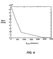
- FIG. 4 is a graph of minimum buffer size B min against peak bit rate R min for a given bit stream, using the second equation above, where the desired initial buffer fullness is set at a constant fraction of the total buffer size.
- the curve in FIG. 4 indicates that in order to transmit the stream at a peak bit rate r, the decoder needs to buffer at least B min (r) bits. Further, as is understood from the graph, higher peak rates require smaller buffer sizes, and hence shorter start-up buffer delays.
- the graph indicates that if the size of the decoder buffer is b, the minimum peak rate required for transmitting the bit stream is the associated R min (b).
- the curve of (R min , B min ) pairs for any bit stream (such as the one in FIG. 4) is piecewise linear and convex.
- the generalized reference decoder 210 can select one point, or linearly interpolate between points, or extrapolate the points to arrive at some points (R interp , B interp ) that are slightly but safely larger than (R min , B min ).
- the buffer size may be safely reduced, in many instances by approximately an order of magnitude relative to a single leaky bucket containing the bit stream at its average rate, whereby the delay is likewise reduced.
- the peak transmission rate may be reduced by a factor of (possibly) four, or the signal to noise ratio (SNR) improved by (possibly) several dB.
- the encoder 202 is enhanced by being arranged to generate at least two sets of leaky bucket parameters 214, e.g., (R 1 ,B 1 ,F 1 ), (R 2 ,B 2 ,F 2 ), ..., (R N ,B N ,F N ), corresponding to at least two points on the Rate-Buffer curve that are useful (e.g., reasonably separated with respect to the range of R and/or B) for the given video or image clip.
- the enhanced encoder 202 then provides these leaky bucket parameter sets, along with the number N thereof, to the generalized reference decoder 210, such as by inserting them in an initial stream header, or alternatively in some out-of-band manner.
- N e.g., dozens of buckets, whereas two-to-four would normally suffice to reasonably represent an R-B curve
- the amount of extra bytes necessary to provide this information e.g., one byte for N, plus eight bytes per leaky bucket model, or parameter set
- the amount of extra bytes necessary to provide this information is negligible when compared to typical video or image data.
- leaky bucket models may be provided for fifteen minute intervals, such that the decoder may change its operating conditions (e.g., its buffer size or the rate) as desired by re-selecting, re-interpolating or re-extrapolating at appropriate times.
- the encoder can choose to pre-select the leaky bucket values and encode the bit stream with a rate control that makes sure that the leaky bucket constraints are met, encode the bit stream and then use the equation described above to compute sets of leaky bucket parameters containing the bit stream at N different values of R, or do both.
- the first approach can be applied to live or on-demand transmission, while the others apply to on-demand.
- the decoder 210 can determine which leaky bucket it wishes to use, knowing the peak bit rate available to it and/or its physical buffer size. Alternatively, the generalized reference decoder 210 may linearly interpolate between or linearly extrapolate from these points to find a suitable set of parameters for a given configuration.
- FIG. 5 shows two leaky bucket parameters sets and their linearly interpolated (R, B) values. For reference, the calculated R-B curve is represented as the finely broken line, while the R and B values provided in the leaky bucket models (R x , B x ) and (R y , B y ) are represented by asterisks.
- the solid line from (R x , B x ) to (R y , B y ) represents the interpolated values. Any R or B pairing chosen on this solid line will properly maintain (e.g., not overflow or underflow) the decoder buffer 208. Leaky bucket parameters can also be extrapolated from these points, represented by the coarsely broken lines in FIG. 5, and again, any R or B pairing chosen on this solid line will properly maintain the decoder buffer 208.
- the decoder need not select, interpolate or extrapolate the leaky bucket parameters, but rather another entity can select the parameters for sending a single set to the decoder, which will then use that one set. For example, given some information such as a decoder's requirements, a server can determine (through selection, interpolation or extrapolation) an appropriate set of leaky bucket parameters to send to a decoder, and then the decoder can decode using only a single set of parameters. A proxy for the server or decoder could also do the selection, interpolation or extrapolation of the leaky bucket information, without the decoder ever seeing more than one leaky bucket.
- the server can decide, possibly with the server and client decoder negotiating the parameters.
- some determination of an appropriate leaky bucket model takes place, either in advance or dynamically, based on at least two leaky bucket models.
- the values of the R-B curve for a given bit stream can be computed from the times at which the highest and lowest fullness values occur in the decoder buffer plot, such as those illustrated in FIG. 3. More particularly, consider two times (tM, tm), of the highest and lowest values of decoder buffer fullness, respectively, for a bit stream contained in a leaky bucket of parameters (R, B, F). The highest and lowest values of fullness may be reached on several occasions, but consider the pair (tM, tm) of largest values such that tM ⁇ tm.
- B is the minimum buffer size that contains the bit stream for the values R, F, then where b(t) is the number of bits for the frame at time t and M is the frame rate in frames/sec.
- n is the number of frames between times tM and tm, and c is the sum of the bits for those frames.
- bit rate range r ⁇ [R-r1, R+r2] such that the largest pair of values tM and tm will remain the same, whereby the above equation corresponds to a straight line that defines the minimum buffer size B associated to the bit rate r.
- bit rate r is outside of the range above, at least one of the values tM and/or tm will change, whereby if r > R+r2, the time distance between tM and tm will be smaller and the value of n in the new straight line defining B(r) will also be smaller, and the slope of the respective line will be larger (less negative). If r ⁇ R-r1, the time distance between tM and tm will be larger and the value of n in the straight line defining B(r) will also be larger. The slope of the line will then be smaller (more negative).
- the values of the pairs (tM, tm) for a range of bit rates (or the associated values of n) and some values of c (at least one for a given pair) may be stored in the header of a bit stream, and thus the piece-wise linear B(r) curve could be obtained using the above equation.
- this equation may be used to simplify the computation of leaky bucket model parameters after an encoder has generated a bit stream.
- the bit stream in FIG. 5 was produced, yielding an average bit rate of 797 Kbps.
- the decoder would need a buffer size of about 18,000 Kbits (R x , B x ). With an initial decoder buffer fullness equal to 18,000 Kbits, the start-up delay would be about 22.5 seconds.
- this encoding (produced with no rate control) shifts bits by up to 22.5 seconds in order to achieve essentially best possible quality for its overall encoded length.
- FIG. 5 also shows that at a peak transmission rate of 2,500 Kbps (e.g., the video bit rate portion of a 2x CD), the decoder would need a buffer size of only 2,272 Kbits, (R y ,B y ), which is reasonable for a consumer hardware device. With an initial buffer fullness equal to 2,272 Kbits, the start-up delay would be only about 0.9 seconds.
- This first leaky bucket parameter set would permit transmission of the video over a constant bit rate channel, with a delay of about 22.5 seconds. While this delay may be too large for many scenarios, it is probably acceptable for internet streaming of movies, for example.
- the second set of leaky bucket parameters would permit transmission of the video over a shared network with peak rate 2,500 Kbps, or would permit local playback from a 2x CD, with a delay of about 0.9 seconds. This sub-second delay is acceptable for random access playback with VCR (video cassette recorder)-like functionality.
- the decoder can linearly interpolate between them (using the above interpolation formulas), for any bit rate R between 797 Kbps and 2,500 Kbps, thereby achieving near-minimal buffer size and delay at any given rate.
- Extrapolation (represented in FIG. 5 by the coarsely broken line) is also more efficient both below 797 Kbps and above 2,500 Kbps, compared to extrapolation with only a single leaky bucket anywhere between 797 Kbps and 2,500 Kbps, inclusive.
- even just two sets of leaky bucket parameters can provide an order of magnitude reduction in buffer size (e.g., 223,662 to 18,000 Kbits in one case, and 18,000 to 2,272 Kbits in another), and an order of magnitude reduction in delay (e.g., 281 to 22.5 seconds in one case and 7.2 to 0.9 seconds in another) at a given peak transmission rate.
- buffer size e.g., 223,662 to 18,000 Kbits in one case, and 18,000 to 2,272 Kbits in another
- an order of magnitude reduction in delay e.g., 281 to 22.5 seconds in one case and 7.2 to 0.9 seconds in another
- the peak transmission rate for a given decoder buffer size it is also possible to reduce the peak transmission rate for a given decoder buffer size. Indeed, as is clear from FIG. 5, if the R-B curve can be obtained by interpolating and/or extrapolating multiple leaky buckets, then it is possible for a decoder with a fixed physical buffer size to choose the minimum peak transmission rate needed to safely decode the bit stream without decoder buffer underflow. For example, if the decoder had a fixed buffer of size 18,000 Kbits, then the peak transmission rate for the encoding can be as low as 797 Kbps.
- using just two leaky buckets reduces the peak transmission rate by a factor of four, for the same decoder buffer size.
- the delay increases from 0.9 to 7.2 seconds at 2,500 Kbps.
- specifying a second leaky bucket can increase the SNR by possibly several dB, with no change in the average bit rate, except for the negligible amount of additional bits per clip to specify the second leaky bucket. This increase in SNR will be visible on playback for every peak transmission rate.
- Buffer capacities of playback devices also vary significantly, from desktop computers with gigabytes of buffer space to small consumer electronic devices with buffer space that is smaller by several orders of magnitude.
- the multiple leaky buckets and the proposed generalized reference decoder of the present invention make it possible for the same bit stream to be transmitted over a variety of channels with the minimum startup delay, minimum decoder buffer requirements, and maximum possible quality. This applies not only to video that is encoded off-line, but also to live video that is broadcast simultaneously through different channels to different devices.
- the proposed generalized reference decoder adds significant flexibility to existing bit streams.
- the generalized reference decoder requires only a small amount of information from the encoder (e.g., at the header of the bit stream) to provide much higher flexibility for bit stream delivery through contemporary networks where bandwidth is variable bandwidth and/or terminals have a variety of bit rate and buffering capabilities.
- the reference decoder of the present invention enables these new scenarios, while reducing the transmission delay to a minimum for the available bandwidth, and in addition, virtually minimizes the channel bit rate requirement for delivery to devices with given physical buffer size limitations.
Abstract
Description

Claims (36)
- A computer implemented method, comprising,
using at least two of sets of parameters comprising rate data and buffer size data to determine an operating condition by selecting:and1) a buffer size based on the rate data; or2) a rate based on the buffer size;
at a time-varying-signal decoder, maintaining encoded data in a buffer in accordance with the operating condition and decoding the encoded data from the buffer. - The method of claim 1 further comprising, receiving the at least two sets of parameters at the time-varying-signal decoder, wherein the time-varying-signal decoder determines the operating condition.
- The method of claim 2 wherein each set of parameters also includes fullness data received at the time-varying-signal decoder.
- The method of claim 2 wherein the at least two sets of parameters are determined by an encoder.
- The method of claim 4 wherein the at least two sets of parameters are received in a stream header along with information indicating a total number of the sets.
- The method of claim 1 wherein using at least two of sets of parameters to determine an operating condition includes selecting one of the sets.
- The method of claim 1 wherein using at least two of sets of parameters to determine an operating condition includes interpolating between data points in at least two of the sets.
- The method of claim 1 wherein using at least two of sets of parameters to determine an operating condition includes extrapolating from data points in at least two of the sets.
- The method of claim 1 wherein selecting a buffer size based on the rate data comprises determining a buffer size that will approach a minimum loading delay.
- The method of claim 1 wherein selecting a rate based on the buffer size comprises determining a minimum required peak transmission rate based on the buffer size.
- The method of claim 1 wherein the operating condition changes at least once during communication of the encoded data to the buffer.
- A computer implemented method, comprising,
at a time-varying-signal decoder, receiving at least two sets of parameters comprising rate and buffer size data;
using at least two of the sets of parameters to determine an operating condition by selecting:maintaining encoded data in a buffer in accordance with the operating condition; and1) a buffer size based on the rate data; or2) a rate based on the buffer size;
decoding the encoded data from the buffer. - The method of claim 12 further comprising providing fullness data to the time-varying-signal decoder.
- The method of claim 12 further comprising, determining the at least two sets of parameters and providing them to the time-varying-signal decoder.
- The method of claim 14 wherein the at least two sets of parameters are determined by an encoder.
- The method of claim 15 wherein the at least two sets of parameters are received in a stream header along with information indicating a total number of the sets.
- The method of claim 12 wherein using at least two of sets of parameters to determine an operating condition includes selecting one of the sets.
- The method of claim 12 wherein using at least two of sets of parameters to determine an operating condition includes interpolating between data points in at least two of the sets.
- The method of claim 12 wherein using at least two of sets of parameters to determine an operating condition includes extrapolating from data points in at least two of the sets.
- The method of claim 12 wherein selecting a buffer size based on the rate data comprises determining a buffer size that will approach a minimum loading delay.
- The method of claim 12 wherein selecting a rate based on the buffer size comprises determining a minimum required peak transmission rate based on the buffer size.
- The method of claim 12 wherein the operating condition changes at least once during communication of the encoded data to the buffer.
- A system for providing time varying signals, comprising:an encoder that provides time-varying signals;an encoder buffer and a decoder buffer that maintain the time-varying signals, the encoder buffer connected to the decoder buffer by a transmission medium;a decoder that removes the time-varying signals from the decoder; anda first mechanism that determines at least two of sets of parameters comprising rate data and buffer size data for maintaining the decoder buffer such that it does not overflow or underflow, anda second mechanism that determines a size of the decoder buffer based on the rate data, or determines a rate of transferring data from the encoder buffer to the decoder buffer based on the buffer size data.
- The system of claim 23 wherein the first mechanism that determines at least two of sets of parameters is incorporated in the encoder.
- The system of claim 23 wherein the second mechanism is incorporated in the decoder.
- The system of claim 23 wherein the first mechanism that determines at least two of sets of parameters is incorporated in the encoder, the second mechanism is incorporated in the decoder, and wherein the encoder communicates the sets of parameters to the decoder.
- The system of claim 26 wherein the encoder communicates the sets of parameters to the decoder via a stream header.
- The system of claim 26 wherein the encoder identifies a total number of the sets of parameters.
- The system of claim 23 wherein each set of parameters also includes fullness data received at the decoder.
- The system of claim 23 wherein the second mechanism determines the size of the decoder buffer based on the rate data, or determines the rate of transferring data, by selecting one of the sets.
- The system of claim 23 wherein the second mechanism determines the size of the decoder buffer based on the rate data, or determines the rate of transferring data, by interpolating between data points in at least two of the sets.
- The system of claim 23 wherein the second mechanism determines the size of the decoder buffer based on the rate data, or determines the rate of transferring data, by extrapolating from data points in at least two of the sets.
- The system of claim 23 wherein the second mechanism determines the size of the decoder buffer by determining a buffer size that will approach a minimum loading delay.
- The system of claim 23 wherein the second mechanism determines the rate data by determining a minimum required peak transmission rate corresponding to a predetermined buffer size.
- The system of claim 23 wherein the second mechanism determines a new size of the decoder buffer based on the rate data and time information.
- The system of claim 23 wherein the second mechanism determines a new rate of transferring data based on the buffer size data size and time information.
Priority Applications (2)
| Application Number | Priority Date | Filing Date | Title |
|---|---|---|---|
| EP06006864.0A EP1753248B1 (en) | 2001-09-19 | 2002-08-27 | Generating and providing parameters for video generalized reference decoder |
| EP06022341.9A EP1746844B1 (en) | 2001-09-19 | 2002-08-27 | Video generalized reference decoder |
Applications Claiming Priority (2)
| Application Number | Priority Date | Filing Date | Title |
|---|---|---|---|
| US955731 | 2001-09-19 | ||
| US09/955,731 US7646816B2 (en) | 2001-09-19 | 2001-09-19 | Generalized reference decoder for image or video processing |
Related Child Applications (4)
| Application Number | Title | Priority Date | Filing Date |
|---|---|---|---|
| EP06006864.0A Division EP1753248B1 (en) | 2001-09-19 | 2002-08-27 | Generating and providing parameters for video generalized reference decoder |
| EP06006864.0A Division-Into EP1753248B1 (en) | 2001-09-19 | 2002-08-27 | Generating and providing parameters for video generalized reference decoder |
| EP06022341.9A Division EP1746844B1 (en) | 2001-09-19 | 2002-08-27 | Video generalized reference decoder |
| EP06022341.9A Division-Into EP1746844B1 (en) | 2001-09-19 | 2002-08-27 | Video generalized reference decoder |
Publications (3)
| Publication Number | Publication Date |
|---|---|
| EP1298938A2 true EP1298938A2 (en) | 2003-04-02 |
| EP1298938A3 EP1298938A3 (en) | 2003-09-24 |
| EP1298938B1 EP1298938B1 (en) | 2017-02-15 |
Family
ID=25497261
Family Applications (3)
| Application Number | Title | Priority Date | Filing Date |
|---|---|---|---|
| EP02019056.7A Expired - Lifetime EP1298938B1 (en) | 2001-09-19 | 2002-08-27 | Generalized reference decoder for image or video processing |
| EP06006864.0A Expired - Lifetime EP1753248B1 (en) | 2001-09-19 | 2002-08-27 | Generating and providing parameters for video generalized reference decoder |
| EP06022341.9A Expired - Lifetime EP1746844B1 (en) | 2001-09-19 | 2002-08-27 | Video generalized reference decoder |
Family Applications After (2)
| Application Number | Title | Priority Date | Filing Date |
|---|---|---|---|
| EP06006864.0A Expired - Lifetime EP1753248B1 (en) | 2001-09-19 | 2002-08-27 | Generating and providing parameters for video generalized reference decoder |
| EP06022341.9A Expired - Lifetime EP1746844B1 (en) | 2001-09-19 | 2002-08-27 | Video generalized reference decoder |
Country Status (9)
| Country | Link |
|---|---|
| US (2) | US7646816B2 (en) |
| EP (3) | EP1298938B1 (en) |
| JP (2) | JP4199973B2 (en) |
| KR (2) | KR100947162B1 (en) |
| CN (2) | CN1848964B (en) |
| DE (1) | DE20222026U1 (en) |
| ES (3) | ES2570190T3 (en) |
| HK (1) | HK1053034B (en) |
| TW (1) | TW574831B (en) |
Cited By (6)
| Publication number | Priority date | Publication date | Assignee | Title |
|---|---|---|---|---|
| EP1501309A1 (en) * | 2002-04-26 | 2005-01-26 | Sony Corporation | Encoding device and method, decoding device and method, edition device and method, recording medium, and program |
| KR100947162B1 (en) * | 2001-09-19 | 2010-03-12 | 마이크로소프트 코포레이션 | Generalized reference decoder for image or video processing |
| WO2010114685A1 (en) * | 2009-03-31 | 2010-10-07 | Alcatel-Lucent Usa Inc. | Compressed video decoding delay reducer |
| CN102572411A (en) * | 2010-12-28 | 2012-07-11 | 索尼公司 | Transmitting apparatus, transmitting method and program |
| EP2457167A4 (en) * | 2009-07-24 | 2015-09-02 | Netflix Inc | Adaptive streaming for digital content distribution |
| US9521354B2 (en) | 2009-07-24 | 2016-12-13 | Netflix, Inc. | Adaptive streaming for digital content distribution |
Families Citing this family (57)
| Publication number | Priority date | Publication date | Assignee | Title |
|---|---|---|---|---|
| EP2027816B1 (en) * | 2000-07-19 | 2012-06-20 | Innovamédica S.A. de C.V. | Catheter for ischemic mucosal damage monitoring in hollow viscous organs |
| WO2003090063A2 (en) * | 2002-04-19 | 2003-10-30 | Koninklijke Philips Electronics N.V. | Output rate change |
| GB0306973D0 (en) * | 2003-03-26 | 2003-04-30 | British Telecomm | Transmitting video |
| US7266147B2 (en) | 2003-03-31 | 2007-09-04 | Sharp Laboratories Of America, Inc. | Hypothetical reference decoder |
| US7380028B2 (en) * | 2003-06-13 | 2008-05-27 | Microsoft Corporation | Robust delivery of video data |
| US7353284B2 (en) * | 2003-06-13 | 2008-04-01 | Apple Inc. | Synchronized transmission of audio and video data from a computer to a client via an interface |
| US7477605B2 (en) * | 2003-06-30 | 2009-01-13 | Alcatel-Lucent Usa Inc. | Methods providing variable granularity for data flow control using a leaky bucket |
| US20050004997A1 (en) * | 2003-07-01 | 2005-01-06 | Nokia Corporation | Progressive downloading of timed multimedia content |
| US7924921B2 (en) * | 2003-09-07 | 2011-04-12 | Microsoft Corporation | Signaling coding and display options in entry point headers |
| US7839930B2 (en) | 2003-11-13 | 2010-11-23 | Microsoft Corporation | Signaling valid entry points in a video stream |
| US7852919B2 (en) * | 2003-09-07 | 2010-12-14 | Microsoft Corporation | Field start code for entry point frames with predicted first field |
| US8213779B2 (en) * | 2003-09-07 | 2012-07-03 | Microsoft Corporation | Trick mode elementary stream and receiver system |
| US7724827B2 (en) * | 2003-09-07 | 2010-05-25 | Microsoft Corporation | Multi-layer run level encoding and decoding |
| US8107531B2 (en) * | 2003-09-07 | 2012-01-31 | Microsoft Corporation | Signaling and repeat padding for skip frames |
| US7961786B2 (en) * | 2003-09-07 | 2011-06-14 | Microsoft Corporation | Signaling field type information |
| US8582659B2 (en) * | 2003-09-07 | 2013-11-12 | Microsoft Corporation | Determining a decoding time stamp from buffer fullness |
| US8345754B2 (en) | 2003-09-07 | 2013-01-01 | Microsoft Corporation | Signaling buffer fullness |
| US7609762B2 (en) * | 2003-09-07 | 2009-10-27 | Microsoft Corporation | Signaling for entry point frames with predicted first field |
| SE0302778D0 (en) | 2003-10-17 | 2003-10-17 | Ericsson Telefon Ab L M | Container format for multimedia presentations |
| US7979886B2 (en) | 2003-10-17 | 2011-07-12 | Telefonaktiebolaget Lm Ericsson (Publ) | Container format for multimedia presentations |
| US7016409B2 (en) * | 2003-11-12 | 2006-03-21 | Sony Corporation | Apparatus and method for use in providing dynamic bit rate encoding |
| GB0406901D0 (en) * | 2004-03-26 | 2004-04-28 | British Telecomm | Transmitting recorded material |
| JP2005333478A (en) * | 2004-05-20 | 2005-12-02 | Mitsumi Electric Co Ltd | Streaming content reproduction method and internet connecting device using the same |
| CN100351869C (en) * | 2004-09-15 | 2007-11-28 | 致伸科技股份有限公司 | Interpolation processing method for digital image |
| US20060104212A1 (en) * | 2004-11-12 | 2006-05-18 | Mao-Hsiung Lee | Method of dynamically determining optimum size of buffer |
| US8218439B2 (en) * | 2004-11-24 | 2012-07-10 | Sharp Laboratories Of America, Inc. | Method and apparatus for adaptive buffering |
| US7543073B2 (en) * | 2004-12-10 | 2009-06-02 | Microsoft Corporation | System and process for performing an exponentially weighted moving average on streaming data to establish a moving average bit rate |
| JP2006174309A (en) * | 2004-12-17 | 2006-06-29 | Ricoh Co Ltd | Animation reproducing apparatus, program, and record medium |
| US20060133494A1 (en) * | 2004-12-17 | 2006-06-22 | Rahul Saxena | Image decoder with context-based parameter buffer |
| US20090222873A1 (en) * | 2005-03-07 | 2009-09-03 | Einarsson Torbjoern | Multimedia Channel Switching |
| JP4066268B2 (en) * | 2005-03-25 | 2008-03-26 | 船井電機株式会社 | Data transmission system |
| US7974193B2 (en) * | 2005-04-08 | 2011-07-05 | Qualcomm Incorporated | Methods and systems for resizing multimedia content based on quality and rate information |
| US8582905B2 (en) * | 2006-01-31 | 2013-11-12 | Qualcomm Incorporated | Methods and systems for rate control within an encoding device |
| BRPI0720702A2 (en) * | 2007-01-05 | 2014-02-18 | Thomson Licensing | REFERENCE HYPOTHETICAL DECODER FOR SCALABLE VIDEO CODING |
| US7656318B2 (en) * | 2007-01-29 | 2010-02-02 | Ntt Docomo, Inc. | Optimized content-based and royalty-based encoding and distribution of media data |
| CN101415078B (en) * | 2007-10-18 | 2010-08-18 | 深圳Tcl新技术有限公司 | Method and apparatus for reducing video recursive noise based on film |
| US8345774B2 (en) * | 2008-01-11 | 2013-01-01 | Apple Inc. | Hypothetical reference decoder |
| EP2101503A1 (en) * | 2008-03-11 | 2009-09-16 | British Telecommunications Public Limited Company | Video coding |
| US9167007B2 (en) * | 2008-06-06 | 2015-10-20 | Amazon Technologies, Inc. | Stream complexity mapping |
| US9047236B2 (en) * | 2008-06-06 | 2015-06-02 | Amazon Technologies, Inc. | Client side stream switching |
| JP5171413B2 (en) * | 2008-06-16 | 2013-03-27 | 三菱電機株式会社 | Content transmission device, content reception device, and content transmission method |
| JP2010028633A (en) * | 2008-07-23 | 2010-02-04 | Nec Personal Products Co Ltd | Digital broadcasting receiver and program |
| EP2200319A1 (en) | 2008-12-10 | 2010-06-23 | BRITISH TELECOMMUNICATIONS public limited company | Multiplexed video streaming |
| EP2219342A1 (en) | 2009-02-12 | 2010-08-18 | BRITISH TELECOMMUNICATIONS public limited company | Bandwidth allocation control in multiple video streaming |
| JP5072893B2 (en) * | 2009-03-25 | 2012-11-14 | 株式会社東芝 | Image encoding method and image decoding method |
| CN101557512B (en) * | 2009-05-19 | 2011-07-20 | 武汉长江通信产业集团股份有限公司 | Method for processing time delay when video terminal receives video data |
| US9521178B1 (en) | 2009-12-21 | 2016-12-13 | Amazon Technologies, Inc. | Dynamic bandwidth thresholds |
| JP5706771B2 (en) | 2010-07-30 | 2015-04-22 | キヤノン株式会社 | Moving picture predictive coding apparatus, control method therefor, and computer program |
| EP2490447A1 (en) * | 2011-02-16 | 2012-08-22 | British Telecommunications Public Limited Company | Compact cumulative bit curves |
| JP5787135B2 (en) * | 2011-04-06 | 2015-09-30 | ソニー株式会社 | Image processing apparatus and method, program, and recording medium |
| US20130208809A1 (en) * | 2012-02-14 | 2013-08-15 | Microsoft Corporation | Multi-layer rate control |
| US10306206B2 (en) * | 2013-07-23 | 2019-05-28 | The Regents Of The University Of California | 3-D motion estimation and online temporal calibration for camera-IMU systems |
| US10283091B2 (en) * | 2014-10-13 | 2019-05-07 | Microsoft Technology Licensing, Llc | Buffer optimization |
| US10404986B2 (en) * | 2015-03-30 | 2019-09-03 | Netflix, Inc. | Techniques for optimizing bitrates and resolutions during encoding |
| US9866596B2 (en) * | 2015-05-04 | 2018-01-09 | Qualcomm Incorporated | Methods and systems for virtual conference system using personal communication devices |
| US9906572B2 (en) | 2015-08-06 | 2018-02-27 | Qualcomm Incorporated | Methods and systems for virtual conference system using personal communication devices |
| US10015216B2 (en) | 2015-08-06 | 2018-07-03 | Qualcomm Incorporated | Methods and systems for virtual conference system using personal communication devices |
Citations (2)
| Publication number | Priority date | Publication date | Assignee | Title |
|---|---|---|---|---|
| EP0515101A2 (en) * | 1991-05-23 | 1992-11-25 | AT&T Corp. | Buffer control for variable bit-rate channel |
| EP0852445A2 (en) * | 1997-01-03 | 1998-07-08 | Ncr International Inc. | Method of optimizing bandwidth for transmitting compressed video data streams |
Family Cites Families (39)
| Publication number | Priority date | Publication date | Assignee | Title |
|---|---|---|---|---|
| US4706260A (en) | 1986-11-07 | 1987-11-10 | Rca Corporation | DPCM system with rate-of-fill control of buffer occupancy |
| CA2000156C (en) | 1989-02-14 | 1995-05-02 | Kohtaro Asai | Picture signal encoding and decoding apparatus |
| JP2787599B2 (en) | 1989-11-06 | 1998-08-20 | 富士通株式会社 | Image signal coding control method |
| GB9012538D0 (en) | 1990-06-05 | 1990-07-25 | Philips Nv | Coding of video signals |
| JPH04297179A (en) | 1991-03-15 | 1992-10-21 | Mitsubishi Electric Corp | Data communication system |
| EP0514663A3 (en) | 1991-05-24 | 1993-07-14 | International Business Machines Corporation | An apparatus and method for motion video encoding employing an adaptive quantizer |
| US5291486A (en) | 1991-08-19 | 1994-03-01 | Sony Corporation | Data multiplexing apparatus and multiplexed data demultiplexing apparatus |
| US5365552A (en) | 1992-11-16 | 1994-11-15 | Intel Corporation | Buffer fullness indicator |
| US5566208A (en) | 1994-03-17 | 1996-10-15 | Philips Electronics North America Corp. | Encoder buffer having an effective size which varies automatically with the channel bit-rate |
| US5541852A (en) * | 1994-04-14 | 1996-07-30 | Motorola, Inc. | Device, method and system for variable bit-rate packet video communications |
| US5933451A (en) * | 1994-04-22 | 1999-08-03 | Thomson Consumer Electronics, Inc. | Complexity determining apparatus |
| JP3674072B2 (en) | 1995-02-16 | 2005-07-20 | 富士ゼロックス株式会社 | Facsimile communication method and facsimile apparatus |
| US5825929A (en) | 1995-10-05 | 1998-10-20 | Microsoft Corporation | Transformation block optimization method |
| FI101332B1 (en) * | 1995-12-18 | 1998-05-29 | Nokia Telecommunications Oy | Discontinuous transmission in a multi-channel high-speed data transmission |
| US6957350B1 (en) | 1996-01-30 | 2005-10-18 | Dolby Laboratories Licensing Corporation | Encrypted and watermarked temporal and resolution layering in advanced television |
| JPH09261266A (en) * | 1996-03-26 | 1997-10-03 | Matsushita Electric Ind Co Ltd | Service information communication system |
| US5952943A (en) | 1996-10-11 | 1999-09-14 | Intel Corporation | Encoding image data for decode rate control |
| JP3709721B2 (en) | 1997-10-03 | 2005-10-26 | ソニー株式会社 | Encoded stream splicing device, encoded stream splicing method, encoded stream generating device, encoded stream generating method, and information processing device and method |
| SG116400A1 (en) | 1997-10-24 | 2005-11-28 | Matsushita Electric Ind Co Ltd | A method for computational graceful degradation inan audiovisual compression system. |
| US6060997A (en) * | 1997-10-27 | 2000-05-09 | Motorola, Inc. | Selective call device and method for providing a stream of information |
| US6775840B1 (en) | 1997-12-19 | 2004-08-10 | Cisco Technology, Inc. | Method and apparatus for using a spectrum analyzer for locating ingress noise gaps |
| JP2002510947A (en) * | 1998-04-02 | 2002-04-09 | サーノフ コーポレイション | Burst data transmission of compressed video data |
| US6629318B1 (en) * | 1998-11-18 | 2003-09-30 | Koninklijke Philips Electronics N.V. | Decoder buffer for streaming video receiver and method of operation |
| US6233226B1 (en) * | 1998-12-14 | 2001-05-15 | Verizon Laboratories Inc. | System and method for analyzing and transmitting video over a switched network |
| KR100584394B1 (en) * | 1998-12-30 | 2006-08-30 | 삼성전자주식회사 | Vocoder parameter control method by real time network monitoring |
| WO2000046989A1 (en) | 1999-02-05 | 2000-08-10 | Sony Corporation | Encoding device, encoding method, decoding device, decoding method, coding system and coding method |
| JP2000286865A (en) * | 1999-03-31 | 2000-10-13 | Toshiba Corp | Continuous media data transmission system |
| KR100390115B1 (en) * | 1999-04-12 | 2003-07-04 | 마츠시타 덴끼 산교 가부시키가이샤 | Image processing method, image processing apparatus and data storage media |
| JP4283950B2 (en) * | 1999-10-06 | 2009-06-24 | パナソニック株式会社 | Network management system |
| KR100636110B1 (en) | 1999-10-29 | 2006-10-18 | 삼성전자주식회사 | Terminal supporting signaling for MPEG-4 tranceiving |
| GB9930788D0 (en) * | 1999-12-30 | 2000-02-16 | Koninkl Philips Electronics Nv | Method and apparatus for converting data streams |
| CN1322759C (en) | 2000-04-27 | 2007-06-20 | 三菱电机株式会社 | Coding apparatus and coding method |
| CA2415299C (en) | 2000-07-25 | 2012-01-24 | Agilevision, L.L.C. | Splicing compressed, local video segments into fixed time slots in a network feed |
| US7454222B2 (en) | 2000-11-22 | 2008-11-18 | Dragonwave, Inc. | Apparatus and method for controlling wireless communication signals |
| US7675994B2 (en) | 2001-04-02 | 2010-03-09 | Koninklijke Philips Electronics N.V. | Packet identification mechanism at the transmitter and receiver for an enhanced ATSC 8-VSB system |
| EP1391065A4 (en) | 2001-05-02 | 2009-11-18 | Strix Systems Inc | Method and system for indicating link quality among neighboring wireless base stations |
| US7646816B2 (en) * | 2001-09-19 | 2010-01-12 | Microsoft Corporation | Generalized reference decoder for image or video processing |
| US8345754B2 (en) | 2003-09-07 | 2013-01-01 | Microsoft Corporation | Signaling buffer fullness |
| US20060143678A1 (en) | 2004-12-10 | 2006-06-29 | Microsoft Corporation | System and process for controlling the coding bit rate of streaming media data employing a linear quadratic control technique and leaky bucket model |
-
2001
- 2001-09-19 US US09/955,731 patent/US7646816B2/en not_active Expired - Lifetime
-
2002
- 2002-08-27 ES ES06006864T patent/ES2570190T3/en not_active Expired - Lifetime
- 2002-08-27 ES ES06022341T patent/ES2570604T3/en not_active Expired - Lifetime
- 2002-08-27 EP EP02019056.7A patent/EP1298938B1/en not_active Expired - Lifetime
- 2002-08-27 EP EP06006864.0A patent/EP1753248B1/en not_active Expired - Lifetime
- 2002-08-27 DE DE20222026U patent/DE20222026U1/en not_active Expired - Lifetime
- 2002-08-27 EP EP06022341.9A patent/EP1746844B1/en not_active Expired - Lifetime
- 2002-08-27 ES ES02019056.7T patent/ES2623635T3/en not_active Expired - Lifetime
- 2002-09-16 KR KR1020020056115A patent/KR100947162B1/en active IP Right Grant
- 2002-09-19 JP JP2002273882A patent/JP4199973B2/en not_active Expired - Lifetime
- 2002-09-19 TW TW91121528A patent/TW574831B/en not_active IP Right Cessation
- 2002-09-19 CN CN2006100799306A patent/CN1848964B/en not_active Expired - Lifetime
- 2002-09-19 CN CNB021432139A patent/CN100461858C/en not_active Expired - Lifetime
-
2003
- 2003-07-22 HK HK03105291.2A patent/HK1053034B/en not_active IP Right Cessation
-
2006
- 2006-05-04 US US11/418,995 patent/US7593466B2/en not_active Expired - Lifetime
-
2007
- 2007-07-23 JP JP2007191483A patent/JP4489794B2/en not_active Expired - Lifetime
- 2007-08-07 KR KR1020070079066A patent/KR100999311B1/en active IP Right Grant
Patent Citations (2)
| Publication number | Priority date | Publication date | Assignee | Title |
|---|---|---|---|---|
| EP0515101A2 (en) * | 1991-05-23 | 1992-11-25 | AT&T Corp. | Buffer control for variable bit-rate channel |
| EP0852445A2 (en) * | 1997-01-03 | 1998-07-08 | Ncr International Inc. | Method of optimizing bandwidth for transmitting compressed video data streams |
Non-Patent Citations (4)
| Title |
|---|
| HSU C-Y ET AL: "JOINT SELECTION OF SOURCE AND CHANNEL RATE FOR VBR VIDEO TRANSMISSION UNDER ATM POLICING CONSTRAINTS" IEEE JOURNAL ON SELECTED AREAS IN COMMUNICATIONS, IEEE INC. NEW YORK, US, vol. 15, no. 6, 1 August 1997 (1997-08-01), pages 1016-1028, XP000694451 ISSN: 0733-8716 * |
| ITU : "Annex B - Hypothetical Reference Decoder (HRD)" ITU-T RECOMMENDATION H.263, February 1998 (1998-02), pages 49-50, XP002248657 * |
| ITU: "Annex C - Video Buffering Verifier (VBV)" ITU-T RECOMMENDATION H.262, February 2000 (2000-02), pages 138-142, XP002248658 * |
| REIBMAN A R ET AL: "CONSTRAINTS ON VARIABLE BIT-RATE VIDEO FOR ATM NETWORKS" IEEE TRANSACTIONS ON CIRCUITS AND SYSTEMS FOR VIDEO TECHNOLOGY, IEEE INC. NEW YORK, US, vol. 2, no. 4, 1 December 1992 (1992-12-01), pages 361-372, XP000323661 ISSN: 1051-8215 * |
Cited By (24)
| Publication number | Priority date | Publication date | Assignee | Title |
|---|---|---|---|---|
| KR100947162B1 (en) * | 2001-09-19 | 2010-03-12 | 마이크로소프트 코포레이션 | Generalized reference decoder for image or video processing |
| US8767837B2 (en) | 2002-04-26 | 2014-07-01 | Sony Corporation | Encoding device and method, decoding device and method, editing device and method, recording medium, and program |
| US10477270B2 (en) | 2002-04-26 | 2019-11-12 | Sony Corporation | Encoding device and method, decoding device and method, editing device and method, recording medium, and program |
| US8571115B2 (en) | 2002-04-26 | 2013-10-29 | Sony Corporation | Encoding device and method, decoding device and method, edition device and method, recording medium, and program |
| EP2403262A3 (en) * | 2002-04-26 | 2012-01-25 | Sony Corporation | Encoding device and method, decoding device and method, editing device and method, recoding medium, and program |
| EP2403264A3 (en) * | 2002-04-26 | 2012-01-25 | Sony Corporation | Encoding device and method, decoding device and method, editing device and method, recoding medium, and program |
| EP2403263A3 (en) * | 2002-04-26 | 2012-01-25 | Sony Corporation | Encoding device and method, decoding device and method, editing device and method, recoding medium, and program |
| EP1501309A1 (en) * | 2002-04-26 | 2005-01-26 | Sony Corporation | Encoding device and method, decoding device and method, edition device and method, recording medium, and program |
| US8315313B2 (en) | 2002-04-26 | 2012-11-20 | Sony Corporation | Encoding device and method, decoding device and method, edition device and method, recording medium, and program |
| US8401088B2 (en) | 2002-04-26 | 2013-03-19 | Sony Corporation | Encoding device and method, decoding device and method, edition device and method, recording medium, and program |
| US10609445B2 (en) | 2002-04-26 | 2020-03-31 | Sony Corporation | Encoding device and method, decoding device and method, editing device and method, recording medium, and program |
| EP1501309A4 (en) * | 2002-04-26 | 2010-11-03 | Sony Corp | Encoding device and method, decoding device and method, edition device and method, recording medium, and program |
| US10659839B2 (en) | 2002-04-26 | 2020-05-19 | Sony Corporation | Encoding device and method, decoding device and method, editing device and method, recording medium, and program |
| US8537902B2 (en) | 2002-04-26 | 2013-09-17 | Sony Corporation | Encoding device and method, decoding device and method, edition device and method, recording medium, and program |
| US10602218B2 (en) | 2002-04-26 | 2020-03-24 | Sony Corporation | Encoding device and method, decoding device and method, editing device and method, recording medium, and program |
| US10602219B2 (en) | 2002-04-26 | 2020-03-24 | Sony Corporation | Encoding device and method, decoding device and method, editing device and method, recording medium, and program |
| US10602220B2 (en) | 2002-04-26 | 2020-03-24 | Sony Corporation | Encoding device and method, decoding device and method, editing device and method, recording medium, and program |
| US10595081B2 (en) | 2002-04-26 | 2020-03-17 | Sony Corporation | Encoding device and method, decoding device and method, editing device and method, recording medium, and program |
| WO2010114685A1 (en) * | 2009-03-31 | 2010-10-07 | Alcatel-Lucent Usa Inc. | Compressed video decoding delay reducer |
| US9769505B2 (en) | 2009-07-24 | 2017-09-19 | Netflix, Inc. | Adaptive streaming for digital content distribution |
| US9648385B2 (en) | 2009-07-24 | 2017-05-09 | Netflix, Inc. | Adaptive streaming for digital content distribution |
| US9521354B2 (en) | 2009-07-24 | 2016-12-13 | Netflix, Inc. | Adaptive streaming for digital content distribution |
| EP2457167A4 (en) * | 2009-07-24 | 2015-09-02 | Netflix Inc | Adaptive streaming for digital content distribution |
| CN102572411A (en) * | 2010-12-28 | 2012-07-11 | 索尼公司 | Transmitting apparatus, transmitting method and program |
Also Published As
| Publication number | Publication date |
|---|---|
| ES2570604T3 (en) | 2016-05-19 |
| EP1746844A3 (en) | 2007-04-18 |
| EP1746844A2 (en) | 2007-01-24 |
| DE20222026U1 (en) | 2011-12-28 |
| JP4199973B2 (en) | 2008-12-24 |
| EP1298938A3 (en) | 2003-09-24 |
| HK1053034B (en) | 2018-01-19 |
| CN1426235A (en) | 2003-06-25 |
| JP2003179665A (en) | 2003-06-27 |
| JP2007329953A (en) | 2007-12-20 |
| KR100947162B1 (en) | 2010-03-12 |
| KR20030025186A (en) | 2003-03-28 |
| ES2623635T3 (en) | 2017-07-11 |
| EP1753248A3 (en) | 2007-04-18 |
| US20060198446A1 (en) | 2006-09-07 |
| CN1848964B (en) | 2011-11-09 |
| JP4489794B2 (en) | 2010-06-23 |
| US20030053416A1 (en) | 2003-03-20 |
| US7593466B2 (en) | 2009-09-22 |
| CN1848964A (en) | 2006-10-18 |
| EP1746844B1 (en) | 2016-03-30 |
| KR20070097375A (en) | 2007-10-04 |
| KR100999311B1 (en) | 2010-12-08 |
| US7646816B2 (en) | 2010-01-12 |
| TW574831B (en) | 2004-02-01 |
| EP1753248A2 (en) | 2007-02-14 |
| EP1298938B1 (en) | 2017-02-15 |
| CN100461858C (en) | 2009-02-11 |
| EP1753248B1 (en) | 2016-03-30 |
| ES2570190T3 (en) | 2016-05-17 |
Similar Documents
| Publication | Publication Date | Title |
|---|---|---|
| US7593466B2 (en) | Generalized reference decoder for image or video processing | |
| USRE48953E1 (en) | Hypothetical reference decoder | |
| Ramanujan et al. | Adaptive streaming of MPEG video over IP networks | |
| US20020131496A1 (en) | System and method for adjusting bit rate and cost of delivery of digital data | |
| CA2505853A1 (en) | Transmission of video | |
| WO2012161652A1 (en) | Methods for transmitting and receiving a digital signal, transmitter and receiver | |
| CN1765103B (en) | Transmitting over a network | |
| US20070110168A1 (en) | Method for generating high quality, low delay video streaming | |
| CN115767149A (en) | Video data transmission method and device | |
| Ribas-Corbera et al. | A flexible decoder buffer model for JVT video coding |
Legal Events
| Date | Code | Title | Description |
|---|---|---|---|
| PUAI | Public reference made under article 153(3) epc to a published international application that has entered the european phase |
Free format text: ORIGINAL CODE: 0009012 |
|
| AK | Designated contracting states |
Kind code of ref document: A2 Designated state(s): AT BE BG CH CY CZ DE DK EE ES FI FR GB GR IE IT LI LU MC NL PT SE SK TR Designated state(s): AT BE BG CH CY CZ DE DK EE ES FI FR GB GR IE IT LI LU MC NL PT SE SK TR |
|
| AX | Request for extension of the european patent |
Extension state: AL LT LV MK RO SI |
|
| PUAL | Search report despatched |
Free format text: ORIGINAL CODE: 0009013 |
|
| RIC1 | Information provided on ipc code assigned before grant |
Ipc: 7H 04N 7/24 B Ipc: 7H 04N 7/50 A |
|
| AK | Designated contracting states |
Kind code of ref document: A3 Designated state(s): AT BE BG CH CY CZ DE DK EE ES FI FR GB GR IE IT LI LU MC NL PT SE SK TR |
|
| AX | Request for extension of the european patent |
Extension state: AL LT LV MK RO SI |
|
| 17P | Request for examination filed |
Effective date: 20040127 |
|
| AKX | Designation fees paid |
Designated state(s): AT BE BG CH CY CZ DE DK EE ES FI FR GB GR IE IT LI LU MC NL PT SE SK TR |
|
| 17Q | First examination report despatched |
Effective date: 20040510 |
|
| RAP1 | Party data changed (applicant data changed or rights of an application transferred) |
Owner name: MICROSOFT TECHNOLOGY LICENSING, LLC |
|
| REG | Reference to a national code |
Ref country code: DE Ref legal event code: R079 Ref document number: 60248666 Country of ref document: DE Free format text: PREVIOUS MAIN CLASS: H04N0007500000 Ipc: H04N0019440000 |
|
| GRAP | Despatch of communication of intention to grant a patent |
Free format text: ORIGINAL CODE: EPIDOSNIGR1 |
|
| RIC1 | Information provided on ipc code assigned before grant |
Ipc: H04N 19/44 20140101AFI20160314BHEP Ipc: H04N 19/46 20140101ALI20160314BHEP Ipc: H04N 19/149 20140101ALI20160314BHEP |
|
| INTG | Intention to grant announced |
Effective date: 20160331 |
|
| GRAJ | Information related to disapproval of communication of intention to grant by the applicant or resumption of examination proceedings by the epo deleted |
Free format text: ORIGINAL CODE: EPIDOSDIGR1 |
|
| GRAP | Despatch of communication of intention to grant a patent |
Free format text: ORIGINAL CODE: EPIDOSNIGR1 |
|
| INTG | Intention to grant announced |
Effective date: 20160824 |
|
| GRAS | Grant fee paid |
Free format text: ORIGINAL CODE: EPIDOSNIGR3 |
|
| GRAA | (expected) grant |
Free format text: ORIGINAL CODE: 0009210 |
|
| AK | Designated contracting states |
Kind code of ref document: B1 Designated state(s): AT BE BG CH CY CZ DE DK EE ES FI FR GB GR IE IT LI LU MC NL PT SE SK TR |
|
| REG | Reference to a national code |
Ref country code: CH Ref legal event code: EP Ref country code: GB Ref legal event code: FG4D |
|
| REG | Reference to a national code |
Ref country code: IE Ref legal event code: FG4D |
|
| REG | Reference to a national code |
Ref country code: AT Ref legal event code: REF Ref document number: 868491 Country of ref document: AT Kind code of ref document: T Effective date: 20170315 |
|
| REG | Reference to a national code |
Ref country code: DE Ref legal event code: R096 Ref document number: 60248666 Country of ref document: DE |
|
| REG | Reference to a national code |
Ref country code: DE Ref legal event code: R082 Ref document number: 60248666 Country of ref document: DE Representative=s name: GRUENECKER PATENT- UND RECHTSANWAELTE PARTG MB, DE |
|
| REG | Reference to a national code |
Ref country code: NL Ref legal event code: FP |
|
| REG | Reference to a national code |
Ref country code: ES Ref legal event code: FG2A Ref document number: 2623635 Country of ref document: ES Kind code of ref document: T3 Effective date: 20170711 |
|
| REG | Reference to a national code |
Ref country code: FR Ref legal event code: PLFP Year of fee payment: 16 |
|
| REG | Reference to a national code |
Ref country code: AT Ref legal event code: MK05 Ref document number: 868491 Country of ref document: AT Kind code of ref document: T Effective date: 20170215 |
|
| PG25 | Lapsed in a contracting state [announced via postgrant information from national office to epo] |
Ref country code: FI Free format text: LAPSE BECAUSE OF FAILURE TO SUBMIT A TRANSLATION OF THE DESCRIPTION OR TO PAY THE FEE WITHIN THE PRESCRIBED TIME-LIMIT Effective date: 20170215 Ref country code: GR Free format text: LAPSE BECAUSE OF FAILURE TO SUBMIT A TRANSLATION OF THE DESCRIPTION OR TO PAY THE FEE WITHIN THE PRESCRIBED TIME-LIMIT Effective date: 20170516 |
|
| PG25 | Lapsed in a contracting state [announced via postgrant information from national office to epo] |
Ref country code: SE Free format text: LAPSE BECAUSE OF FAILURE TO SUBMIT A TRANSLATION OF THE DESCRIPTION OR TO PAY THE FEE WITHIN THE PRESCRIBED TIME-LIMIT Effective date: 20170215 Ref country code: PT Free format text: LAPSE BECAUSE OF FAILURE TO SUBMIT A TRANSLATION OF THE DESCRIPTION OR TO PAY THE FEE WITHIN THE PRESCRIBED TIME-LIMIT Effective date: 20170615 Ref country code: AT Free format text: LAPSE BECAUSE OF FAILURE TO SUBMIT A TRANSLATION OF THE DESCRIPTION OR TO PAY THE FEE WITHIN THE PRESCRIBED TIME-LIMIT Effective date: 20170215 Ref country code: BG Free format text: LAPSE BECAUSE OF FAILURE TO SUBMIT A TRANSLATION OF THE DESCRIPTION OR TO PAY THE FEE WITHIN THE PRESCRIBED TIME-LIMIT Effective date: 20170515 |
|
| PG25 | Lapsed in a contracting state [announced via postgrant information from national office to epo] |
Ref country code: SK Free format text: LAPSE BECAUSE OF FAILURE TO SUBMIT A TRANSLATION OF THE DESCRIPTION OR TO PAY THE FEE WITHIN THE PRESCRIBED TIME-LIMIT Effective date: 20170215 Ref country code: EE Free format text: LAPSE BECAUSE OF FAILURE TO SUBMIT A TRANSLATION OF THE DESCRIPTION OR TO PAY THE FEE WITHIN THE PRESCRIBED TIME-LIMIT Effective date: 20170215 Ref country code: CZ Free format text: LAPSE BECAUSE OF FAILURE TO SUBMIT A TRANSLATION OF THE DESCRIPTION OR TO PAY THE FEE WITHIN THE PRESCRIBED TIME-LIMIT Effective date: 20170215 |
|
| REG | Reference to a national code |
Ref country code: DE Ref legal event code: R097 Ref document number: 60248666 Country of ref document: DE |
|
| PG25 | Lapsed in a contracting state [announced via postgrant information from national office to epo] |
Ref country code: DK Free format text: LAPSE BECAUSE OF FAILURE TO SUBMIT A TRANSLATION OF THE DESCRIPTION OR TO PAY THE FEE WITHIN THE PRESCRIBED TIME-LIMIT Effective date: 20170215 |
|
| PLBE | No opposition filed within time limit |
Free format text: ORIGINAL CODE: 0009261 |
|
| STAA | Information on the status of an ep patent application or granted ep patent |
Free format text: STATUS: NO OPPOSITION FILED WITHIN TIME LIMIT |
|
| REG | Reference to a national code |
Ref country code: HK Ref legal event code: GR Ref document number: 1053034 Country of ref document: HK |
|
| 26N | No opposition filed |
Effective date: 20171116 |
|
| REG | Reference to a national code |
Ref country code: CH Ref legal event code: PL |
|
| PG25 | Lapsed in a contracting state [announced via postgrant information from national office to epo] |
Ref country code: MC Free format text: LAPSE BECAUSE OF FAILURE TO SUBMIT A TRANSLATION OF THE DESCRIPTION OR TO PAY THE FEE WITHIN THE PRESCRIBED TIME-LIMIT Effective date: 20170215 |
|
| PG25 | Lapsed in a contracting state [announced via postgrant information from national office to epo] |
Ref country code: CH Free format text: LAPSE BECAUSE OF NON-PAYMENT OF DUE FEES Effective date: 20170831 Ref country code: LI Free format text: LAPSE BECAUSE OF NON-PAYMENT OF DUE FEES Effective date: 20170831 |
|
| REG | Reference to a national code |
Ref country code: IE Ref legal event code: MM4A |
|
| REG | Reference to a national code |
Ref country code: BE Ref legal event code: MM Effective date: 20170831 |
|
| PG25 | Lapsed in a contracting state [announced via postgrant information from national office to epo] |
Ref country code: LU Free format text: LAPSE BECAUSE OF NON-PAYMENT OF DUE FEES Effective date: 20170827 |
|
| REG | Reference to a national code |
Ref country code: FR Ref legal event code: PLFP Year of fee payment: 17 |
|
| PG25 | Lapsed in a contracting state [announced via postgrant information from national office to epo] |
Ref country code: IE Free format text: LAPSE BECAUSE OF NON-PAYMENT OF DUE FEES Effective date: 20170827 |
|
| PG25 | Lapsed in a contracting state [announced via postgrant information from national office to epo] |
Ref country code: BE Free format text: LAPSE BECAUSE OF NON-PAYMENT OF DUE FEES Effective date: 20170831 |
|
| PG25 | Lapsed in a contracting state [announced via postgrant information from national office to epo] |
Ref country code: CY Free format text: LAPSE BECAUSE OF NON-PAYMENT OF DUE FEES Effective date: 20170215 |
|
| PG25 | Lapsed in a contracting state [announced via postgrant information from national office to epo] |
Ref country code: TR Free format text: LAPSE BECAUSE OF FAILURE TO SUBMIT A TRANSLATION OF THE DESCRIPTION OR TO PAY THE FEE WITHIN THE PRESCRIBED TIME-LIMIT Effective date: 20170215 |
|
| PGFP | Annual fee paid to national office [announced via postgrant information from national office to epo] |
Ref country code: NL Payment date: 20210623 Year of fee payment: 20 |
|
| PGFP | Annual fee paid to national office [announced via postgrant information from national office to epo] |
Ref country code: GB Payment date: 20210625 Year of fee payment: 20 |
|
| PGFP | Annual fee paid to national office [announced via postgrant information from national office to epo] |
Ref country code: FR Payment date: 20210714 Year of fee payment: 20 Ref country code: IT Payment date: 20210712 Year of fee payment: 20 |
|
| PGFP | Annual fee paid to national office [announced via postgrant information from national office to epo] |
Ref country code: ES Payment date: 20210903 Year of fee payment: 20 Ref country code: DE Payment date: 20210622 Year of fee payment: 20 |
|
| REG | Reference to a national code |
Ref country code: DE Ref legal event code: R071 Ref document number: 60248666 Country of ref document: DE |
|
| REG | Reference to a national code |
Ref country code: NL Ref legal event code: MK Effective date: 20220826 |
|
| REG | Reference to a national code |
Ref country code: ES Ref legal event code: FD2A Effective date: 20220902 |
|
| REG | Reference to a national code |
Ref country code: GB Ref legal event code: PE20 Expiry date: 20220826 |
|
| PG25 | Lapsed in a contracting state [announced via postgrant information from national office to epo] |
Ref country code: GB Free format text: LAPSE BECAUSE OF EXPIRATION OF PROTECTION Effective date: 20220826 Ref country code: ES Free format text: LAPSE BECAUSE OF EXPIRATION OF PROTECTION Effective date: 20220828 |
|
| P01 | Opt-out of the competence of the unified patent court (upc) registered |
Effective date: 20230522 |