EP1298537B1 - Verfahren und Vorrichtung zur Aktualisierung des Cachespeichers - Google Patents
Verfahren und Vorrichtung zur Aktualisierung des Cachespeichers Download PDFInfo
- Publication number
- EP1298537B1 EP1298537B1 EP01123095A EP01123095A EP1298537B1 EP 1298537 B1 EP1298537 B1 EP 1298537B1 EP 01123095 A EP01123095 A EP 01123095A EP 01123095 A EP01123095 A EP 01123095A EP 1298537 B1 EP1298537 B1 EP 1298537B1
- Authority
- EP
- European Patent Office
- Prior art keywords
- computer
- cache
- journal
- journal entry
- digest
- Prior art date
- Legal status (The legal status is an assumption and is not a legal conclusion. Google has not performed a legal analysis and makes no representation as to the accuracy of the status listed.)
- Expired - Lifetime
Links
Images



Classifications
-
- G—PHYSICS
- G06—COMPUTING OR CALCULATING; COUNTING
- G06F—ELECTRIC DIGITAL DATA PROCESSING
- G06F16/00—Information retrieval; Database structures therefor; File system structures therefor
- G06F16/90—Details of database functions independent of the retrieved data types
- G06F16/95—Retrieval from the web
- G06F16/957—Browsing optimisation, e.g. caching or content distillation
- G06F16/9574—Browsing optimisation, e.g. caching or content distillation of access to content, e.g. by caching
Definitions
- the present invention generally relates to electronic data processing, and more particularly, relates to method, computer program product and system for adjusting caches in a network.
- Scalability of a computer system means that system performance can be improved by adding more hardware in a linear way. System performance can be measured by the time the system needs to respond to an user interaction (response time of the system).
- An example for a client-server system is the SAP R/3TM system, where one database server stores all application data.
- the database server can be accessed substantially simultaneously by a plurality of application users using a plurality of client computers. Each client computer accesses at least an application server.
- a plurality of application servers accesses the database server.
- Application servers handle the application logic, thus taking away load from the database server.
- the application servers store copies of original database objects in a so-called buffer area (cache) of their memories to reduce the number of accesses to the original database objects.
- internet applications With the extension of internal corporate networks through internet applications the number of users in a corporate network becomes much larger than the number of users in an internal client-server system. Further, internet applications do not have exactly one source of objects, such as application data, as it is the case in client-server systems, where all objects are stored on one database server.
- Cache Digests Computer Networks and ISDN Systems, Vol. 30, No. 22-23, November 1998 refers to cache digests for cooperative Web caching. Cache digests allow proxies to make information abut their cache contents available to peers in a compact form.
- the present invention provides computer-implemented method, computer program product and computer system to solve the technical problem of fast access to objects that are distributed in a computer network, such as the internet, wherein the access can occur substantially simultaneously from multiple computers in the network by a deliberate number of users.
- the idea of the present invention is to overcome this problem by removing a bottleneck that exists in prior art systems, because data, which have to be shared between several computers, only can reside on one single central location (e.g. a specific database server computer) in the network.
- the present invention takes advantage of the fact that most objects are not needed in an absolutely temporal precise manner but still have to be consistent within a certain time interval.
- objects having a static character such as master data of an application system
- "Buffer” stands for storing a copy of the object intermediately in a cache memory portion of the network computer.
- a further technical problem is consistency of multiple copies of the same object in multiple caches to prevent a computer user from working with an old version of the object.
- substantially simultaneous access to an object by a large number of users is achieved by storing buffered copies of the object in the caches of a plurality of network computers.
- Each buffered copy of the object should be identical with the original object that is stored somewhere in a database of a network computer.
- the inventive method, computer system and computer program products adjust the caches of multiple network computers at a predefined synchronization frequency by deleting obsolete copies of objects from the caches.
- the synchronization frequency is defined as the reciprocal value of one synchronization interval.
- the synchronization interval is the time between two consecutive cache adjustments of two computers. It is not necessary that the synchronization frequency is constant over time.
- the present invention guarantees validity of buffered object copies within two synchronization intervals. Thereby, it is not important for the invention that both synchronization intervals have the same length.
- a consistent copy of the object is provided at a network computer where the object is needed, rather than retrieving the original object each time when a user tries to access.
- the present invention solves the aforementioned problem of consistency of multiple copies of the same object in multiple caches through the features of a computer-implemented cache adjustment mechanism that is described as computer-implemented method as claimed in claim 1, computer system as claimed in claim 11 and corresponding computer program products according to claims 4 and 5.
- This cache adjustment mechanism has the advantage that two C-computers have journals that are adjusted after the inventive method has been applied to the C-computers.
- a predefined maximum time interval defines how far into the past journal entries are considered in the synchronization mechanism.
- this C-computer when going online again, re-synchronizes with the journal entries of the other C-computers within the maximum time interval.
- the predefined synchronization topology can be disturbed.
- a C-computer that wants to synchronize with an offline C-computer can find an online C-computer via a random generator and continue with the synchronization.
- the first method optionally comprises the further step i): Synchronizing the first digest matrix with the second digest matrix.
- step i) is performed after the updating step.
- C-computers Multiple buffered copies of the object become available at multiple locations (C-computers), thus eliminating the bottleneck of a single content source (e.g. a single database server).
- a single content source e.g. a single database server.
- the retrieval of the object from a cache memory is much faster than the retrieval directly from a database.
- Computers 903-902 are coupled via inter-computer network 990.
- Computer 903 comprises processor 910, memory 920, bus 930, and, optionally, input device 940 and output device 950 (I/O devices, user interface 960).
- the invention is present by computer program product 100 (CPP), program carrier 970 and program signal 980, collectively "program”.
- computer 904/902 is sometimes referred to as "remote computer", computer 904/902 is, for example, a server, a router, a peer device or other common network node, and typically comprises many or all of the elements described relative to computer 903.
- Computer 903 is a conventional personal computer (PC), a desktop and hand-held device, a multiprocessor computer, a pen computer, a microprocessor-based or programmable consumer electronics, a minicomputer, a mainframe computer, a personal mobile computing device, a mobile phone, a portable or stationary personal computer, a palmtop computer or the like.
- PC personal computer
- desktop and hand-held device a multiprocessor computer
- pen computer a microprocessor-based or programmable consumer electronics
- minicomputer a mainframe computer
- a personal mobile computing device a mobile phone
- portable or stationary personal computer a palmtop computer or the like.
- Processor 910 is, for example, a central processing unit (CPU), a micro-controller unit (MCU), digital signal processor (DSP), or the like.
- CPU central processing unit
- MCU micro-controller unit
- DSP digital signal processor
- Memory 920 symbolizes elements that temporarily or permanently store data and instructions. Although memory 920 is conveniently illustrated as part of computer 903, memory function can also be implemented in network 990, in computers 904/902 and in processor 910 itself (e.g., cache, register), or elsewhere. Memory 920 can be a read only memory (ROM), a random access memory (RAM), or a memory with other access options.
- ROM read only memory
- RAM random access memory
- Memory 920 is physically implemented by computer-readable media, such as, for example: (a) magnetic media, like a hard disk, a floppy disk, or other magnetic disk, a tape, a cassette tape; (b) optical media, like optical disk (CD-ROM, digital versatile disk - DVD); (c) semiconductor media, like DRAM, SRAM, EPROM, EEPROM, memory stick, or by any other media, like paper.
- computer-readable media such as, for example: (a) magnetic media, like a hard disk, a floppy disk, or other magnetic disk, a tape, a cassette tape; (b) optical media, like optical disk (CD-ROM, digital versatile disk - DVD); (c) semiconductor media, like DRAM, SRAM, EPROM, EEPROM, memory stick, or by any other media, like paper.
- memory 920 is distributed across different media. Portions of memory 920 can be removable or non-removable.
- computer 903 uses devices well known in the art such as, for example, disk drives, tape drives.
- Memory 920 stores support modules such as, for example, a basic input output system (BIOS), an operating system (OS), a program library, a compiler, an interpreter, and a text- processing tool.
- support modules are commercially available and can be installed on computer 903 by those of skill in the art. For simplicity, these modules are not illustrated.
- CPP 100 comprises program instructions and - optionally - data that cause processor 910 to execute method steps of the present invention. Method steps are explained with more detail below.
- CPP 100 defines the operation of computer 903 and its interaction in network system 999.
- CPP 100 can be available as source code in any programming language, and as object code ("binary code") in a compiled form. Persons of skill in the art can use CPP 100 in connection with any of the above support modules (e.g., compiler, interpreter, operating system).
- CPP 100 is illustrated as being stored in memory 920, CPP 100 can be located elsewhere. CPP 100 can also be embodied in carrier 970.
- Carrier 970 is illustrated outside computer 903. For communicating CPP 100 to computer 903, carrier 970 is conveniently inserted into input device 940.
- Carrier 970 is implemented as any computer readable medium, such as a medium largely explained above (cf. memory 920).
- carrier 970 is an article of manufacture comprising a computer readable medium having computer readable program code means embodied therein for executing the method of the present invention.
- program signal 980 can also embody computer program 100. Signal 980 travels on network 990 to computer 903.
- program carrier 970 Having described CPP 100, program carrier 970, and program signal 980 in connection with computer 903 is convenient.
- program carrier 971/972 (not shown) and program signal 981/982 embody computer program product (CPP) 101/102 to be executed by processor 911/912 (not shown) in computers 904/902, respectively.
- processor 911/912 not shown
- Input device 940 symbolizes a device that provides data and instructions for processing by computer 903.
- device 940 is a keyboard, a pointing device (e.g., mouse, trackball, cursor direction keys), microphone, joystick, game pad, CCanner.
- a wireless receiver e.g., with satellite dish or terrestrial antenna
- a sensor e.g., a thermometer
- a counter e.g., goods counter in a factory.
- Input device 940 can serve to read carrier 970.
- Output device 950 symbolizes a device that presents instructions and data that have been processed.
- a monitor or a display (cathode ray tube (CRT), flat panel display, liquid crystal display (LCD), speaker, printer, plotter, vibration alert device.
- CTR cathode ray tube
- LCD liquid crystal display
- speaker printer
- vibration alert device Similar as above, output device 950 communicates with the user, but it can also communicate with further computers.
- Input device 940 and output device 950 can be combined to a single device; any device 940 and 950 can be provided optional.
- Bus 930 and network 990 provide logical and physical connections by conveying instruction and data signals. While connections inside computer 903 are conveniently referred to as “bus 930", connections between computers 903-902 are referred to as “network 990". Optionally, network 990 comprises gateways being computers that specialize in data transmission and protocol conversion.
- Devices 940 and 950 are coupled to computer 903 by bus 930 (as illustrated) or by network 990 (optional). While the signals inside computer 903 are mostly electrical signals, the signals in network are electrical, magnetic, optical or wireless (radio) signals.
- Networking environments are commonplace in offices, enterprise-wide computer networks, intranets and the internet (i.e. world wide web). The physical distance between a remote computer and computer 903 is not important.
- Network 990 can be a wired or a wireless network.
- network 990 is, for example, a local area network (LAN), a wide area network (WAN), a public switched telephone network (PSTN); a Integrated Services Digital Network (ISDN), an infra-red (IR) link, a radio link, like Universal Mobile Telecommunications System (UMTS), Global System for Mobile Communication (GSM), Code Division Multiple Access (CDMA), or satellite link.
- LAN local area network
- WAN wide area network
- PSTN public switched telephone network
- ISDN Integrated Services Digital Network
- IR infra-red
- radio link like Universal Mobile Telecommunications System (UMTS), Global System for Mobile Communication (GSM), Code Division Multiple Access (CDMA), or satellite link.
- UMTS Universal Mobile Telecommunications System
- GSM Global System for
- Transmission protocols and data formats are known, for example, as transmission control protocol/internet protocol (TCP/IP), hyper text transfer protocol (HTTP), secure HTTP, wireless application protocol, unique resource locator (URL), a unique resource identifier (URI), hyper text markup language HTML, extensible markup language (XML), extensible hyper text markup language (XHTML), wireless application markup language (WML), etc.
- TCP/IP transmission control protocol/internet protocol
- HTTP hyper text transfer protocol
- HTTP secure HTTP
- wireless application protocol unique resource locator
- URL unique resource locator
- URI unique resource identifier
- HTML hyper text markup language
- XML extensible markup language
- XHTML extensible hyper text markup language
- WML wireless application markup language
- An interface can be, for example, a serial port interface, a parallel port interface, a game port, a universal serial bus (USB) interface, an internal or external modem, a video adapter, or a sound card.
- USB universal serial bus
- FIG. 2 illustrates details of two different states ( FIG. 2A , FIG. 2B ) of a preferred embodiment of computer system 999.
- Hardware components of computer system 999 are illustrated by dotted lines or frames, whereas software related components are illustrated by solid lines or frames.
- IDs e.g. OC3 for third computer 903
- values e.g. OC3/2 for S-mark 121-2
- FIG. 2A shows four computers 901, 902, 903, 904 of computer system 999 that are connected via network 990.
- First computer 901 (CC1) and second computer 902 (CC2) are C-computers.
- Third computer 903 (OC3) and forth computer 904 (OC4) are O-computers.
- First computer 901 has first cache 921-1.
- first cache 921-1 stores objects 192, 193 (OC4/01, OC4/02) originating in forth computer 904 (OC4) and stores object 191* (OC3/02) originating in third computer 903 (OC3).
- Second computer 902 has second cache 922-1.
- second cache 922-1 stores objects 190, 191 (OC3/01, OC3/02) originating in third computer 903 (OC3).
- First computer 901 stores first journal 111.
- First journal 111 comprises all journal entries relating to object modifications on forth computer 904.
- first journal 111 further stores a journal entry (OC3/1) that corresponds to a modification of an object (03) on third computer 903 (OC3).
- Second computer 902 stores second journal 112.
- Second journal 112 comprises all journal entries 112-10, 112-11 relating to third computer 903.
- forth computer 904 (OC4) stores an own journal (not shown) to track the change history of all objects of forth computer 904
- third computer 903 (OC3) stores its own journal (not shown) to track the change history of all objects of third computer 903.
- journal entries originating in an origin computer are transmitted to a corresponding journal of a cache computer, where the origin computer is assigned to.
- the origin computer intermediately stores the journal entries and the cache computer loads new journal entries of the assigned origin computer at predefined time intervals.
- the new journal entry replaces an old journal entry for the specific object.
- new journal entries are appended to the corresponding journal.
- second journal 112 has two journal entries 112-10, 112-11 that both refer to third computer 903 (OC3).
- Each journal entry has a key that comprises an ID (OC) of the corresponding O-computer (e.g. OC3) and an USN (e.g. 1).
- the key e.g. OC3/1 is stored in column 112-1 of journal 112.
- each journal entry comprises an ID (e.g. 01) of the modified object (e.g. 01, 02) in column 112-2.
- Journal 111 comprises columns 111-1 and 111-2 that are functionally equivalent to columns 112-1 and 112-2 respectively.
- first computer 901 stores S-vector 121.
- S-vector 121 comprises S-mark 121-2.
- S-mark 121-2 stores a representation (OC3/1) of a previous latest second journal entry 112-11 at the time of the last synchronization between the two C-computers 901, 902.
- the value OC3/1 of S-mark 121-2 indicates that the latest previous second journal entry has the key OC3/1.
- First computer 901 receives S-trigger 986-1, which causes first computer 901 to synchronize with second computer 902.
- First computer 901 sends 420 S-vector 121 to second computer 902.
- Comparator 160 of second computer 902 compares 430 S-mark 121-2 (OC3/1) with a comparable portion 112-1 of second journal 112.
- second journal 112 has a current latest journal entry 112-10 referring to third computer 903 (OC3) that is newer than previous latest second journal entry 112-11, second computer 902 (CC2) identifies each second journal entry 112-10 that is newer than previous latest second journal entry 112-11 and that refers to third computer 903.
- the key of current latest journal entry 112-10 OC3/2) originating from corresponding third computer 903 (OC3) has an USN portion that is higher than the USN portion of the key of previous latest journal entry 112-11 (2 ⁇ 1). Therefore, in the example, journal entry 112-10 is identified.
- second computer performs comparison 430 with the identification of new journal entries referring to further 0-computers for each S-mark.
- FIG. 2B illustrates computer system 999 after the cache adjustment of first cache 921-1.
- second computer 902 transmits 440 identified second journal entry 112-10 (OC3/2) to first journal 111, where it is added as first journal entry 111-10.
- First journal entry 111-10 indicates that the original object OC3/02 (not shown, stored on third computer 903) that corresponds to object 191* (OC3/02) was modified since object 191* was loaded into first cache 921-1. Therefore, object 191* most likely is no longer consistent with the corresponding original object on third computer 903. As a consequence, first computer 901 (CC1) adjusts 450 first cache 921-1 by deleting object 191* (crossed out) in first cache 921-1.
- S-mark 121-2 of S-vector 121 is updated 460, accordingly, by replacing the old value (OC3/1) with a representation (e.g. the key) of the corresponding latest first journal entry 111-10 (OC3/2), which is a copy of current latest second journal entry 110-10.
- first computer 901 knows the change history of all objects on third computer 903.
- first computer 901 also knows the change history of objects on the corresponding O-computers.
- S-vector 121 stores at least S-mark 121-2 on first computer 901.
- S-mark 121-2 represents latest second journal entry 112-10 and is comparable with a bookmark.
- first computer 901 receives a further S-trigger and comparator 160 identifies a need to transmit additional journal entries from second journal 112 to first journal 111, the bookmark is used to identify the additional journal entries.
- the additional journal entries have an USN portion higher than the USN portion of the bookmark.
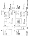
- FIG. 3 illustrates details of two further states ( FIG. 3A , FIG. 3B ) of the preferred embodiment of computer system 999.
- hardware components of computer system 999 are illustrated by dotted lines or frames, whereas software related components are illustrated by solid lines or frames.
- FIG. 3A shows the four computers 901, 902, 903, 904 of computer system 999 as described under FIG. 2 .
- first cache 921-1 stores objects 192 (OC4/01) and 193 (OC4/02). Objects 192, 193 were loaded from forth computer 904 (OC4). Second cache 922-1 stores objects 190 (OC3/01) and 191 (OC3/02). Objects 190, 191 were loaded from third computer 903 (OC3).
- first computer 901 has first digest matrix 141 and second computer 902 has second digest matrix 142.
- First digest matrix 141 comprises column 141-1 (CC) and column 141-2 (OC/COR).
- Column 141-1 stores IDS of C-computers (e.g. CC1, CC2) of computer system 999.
- Column 141-2 stores a content digest (e.g. content digest CC1 141-12) of the corresponding C-computer in column 141-1.
- Each content digest comprises representations of objects that are stored in the cache of the corresponding C-computer.
- each object representation is implemented as a bit pattern.
- Second digest matrix 142 comprises columns 142-1 and 142-2 that are functionally equivalent with columns 141-1 and 141-2, respectively.
- First computer 901 receives 413 request 190-1 for object 190.
- request 190-1 has the format of an object key (e.g. OC3/01).
- First computer 901 uses first digest matrix 141 to identify 416 second computer 902 (CC2) as a supplier of requested object 190, because content digest 141-22 of C-computer 902 (CC2) comprises the object representation OC3/01R of the requested object 190 (OC3/01).
- First computer 901 sends 420 object request 190-1 to second computer 902 (CC2), to retrieve corresponding object 190 from second cache 922-1.
- FIG. 3B illustrates computer system 999 after adjusting first cache 926-1 according to the result of the distribution of object 190.
- Second computer 902 (CC2) transmits 440 object 190 from second cache 922-1 to first cache 921-1 resulting in object 190*.
- First computer 901 updates 450 its content digest 141-22 in first digest matrix 141 by adding an object representation (OC3/01R) for object 190*.
- Second computer 902 (CC1) synchronizes 460 second digest matrix 142 with updated first digest matrix 141.
- This optional cache adjustment mechanism is the availability of the same object (OC3/01) on multiple computers in computer system 999 (e.g. object 190 on second computer 902 and object 190* on first computer 901). This removes the bottleneck of a single source of data. Further, the information about the multiple storage locations of an object is spread by synchronizing the digest matrices of C-computers in computer system 999.
- FIG. 4 illustrates cache adjustment method 400 according to the present invention.
- Method 400 comprises the steps providing journals 410, sending synchronization vector 420, comparing synchronization mark 430, transmitting journal entries 440, adjusting cache 450 and updating synchronization vector 460.
- Method 400 comprises the further steps: receiving object key 413, identifying object supplier 416 and optionally synchronizing digest matrices 465.
- the steps 413, 416 and 465 are illustrated by dashed frames. It is not necessary for the present invention that the steps are performed in the same order as described. The steps are now explained in detail.
- first and second computers 901, 902 are C-computers.
- First computer 901 has first cache 921-1 (cf. FIG. 2A ) and provides first journal 111 (cf. FIG. 2A ).
- Second computer 902 has second cache 922-1 (cf. FIG. 2A ) and provides second journal 112 (cf. FIG. 2A ).
- first and second journals 111, 112 are tables that are stored in corresponding memories (e.g. 921, 922 cf. FIG.
- journal entry 112-10 (cf. FIG. 2A ) of second journal 112 indicates a modification of object 02 (column 112-2 of journal entry 112-10) on third computer 903 (cf. FIG. 2A ).
- third computer 903 is an O-computer.
- Journal entry 112-10 has a unique key 112-1 that comprises the ID of third computer 903 (OC3) and an USN (2).
- third computer 903 creates a journal entry with a new USN for an object (e.g. 02) in second journal 112, each time when the object is changed (e.g. modified, deleted).
- the USNs referring to an O-computer are generated as strictly increasing or strictly decreasing numbers over time.
- first computer 901 preferably, sends S-vector 121 to second computer 902 via network 990 (cf. FIG. 2A ) caused by S-trigger 986-1.
- S-vector 121 comprises S-mark 121-2.
- S-mark 121-2 stores a representation (e.g. the key) of the previous latest second journal entry (OC3/1) with respect to third computer 903 (OC3) at the time of the last synchronization between first and second computers 901, 902.
- an initial value e.g. OC3/0
- comparator 160 of second computer 902 compares 430 S-mark 121-2 (OC3/1) with a comparable portion 112-1 of second journal 112. If second journal 112 has a current latest journal entry 112-10 referring to third computer 903 (OC3) that is newer than previous latest second journal entry 112-11, second computer 902 (CC2) identifies each second journal entry 112-10 that is newer than previous latest second journal entry 112-11 and that refers to third computer 903. In case no such current latest journal entry 112-10 exists, method 400 waits for the next S-trigger to restart (arrow to step 410).
- journal entry 112-10 is identified.
- the result of the comparing 430 step is a list of all journal entries (e.g. 112-10) of second journal 112 that refer to third computer 903 (OC3) and were created since the last synchronization between first and second computer 901, 902.
- comparator 160 considers all journal entries that were generated by third computer 903 within a predefined time interval prior to S-trigger 986-1.
- the time interval is defined in a way that journal entries that were generated outside the time interval are outdated.
- the comparing synchronization step 430 is repeated for all S-marks stored in S-vector 121.
- second computer 902 transmits the list of journal entries resulting from the comparison step 430 to first journal 111 (via network 990).
- journal entry 112-10 (OC3/2) of second journal 112 is transmitted to first journal 111, where it is added as journal entry 111-10 (cf. FIG.2B ).
- First journal 111 has now synchronized with second journal 112. That is, first computer 901 has the same knowledge as second computer 902 about the status of objects of at least third computer 903.
- first computer 901 uses the information of new journal entries (e.g. 111-10) in first journal 111 to adjust first cache 921-1.
- journal entry 111-10 indicates that the original object OC3/02 (on third computer 903; not shown) that corresponds to object 191* (OC3/02) (cf. FIG. 2A ) was modified since object 191* was loaded into first cache 921-1. Therefore, object 191* most likely is no longer consistent with the corresponding original object on third computer 903.
- first computer 901 (CC1) adjusts 450 first cache 921-1 by deleting (cf. FIG. 2B , crossed out) object 191* from first cache 921-1.
- first computer 901 updates on first computer 901 at least S-mark 121-2 of S-vector 121 with the key of current latest journal entry 111-10 (OC3/2) and referring to third computer 903 (OC3).
- Updated S-mark 121-2 serves as a bookmark for second journal 112 when the next S-trigger occurs.
- the steps 410-450 of method 400 describe a basic cache adjustment mechanism for multiple C-computers in a network to synchronize journals that trace information about the change status of objects on O-computers and to adjust the content of corresponding caches, accordingly.
- This mechanism is complemented by additional characteristics of steps 410-460 and further steps 413, 416 and 465 to provide a more comprehensive cache adjustment mechanism.
- first computer 901 further provides first digest matrix 141 (cf. FIG. 3A ) and second computer 902 (CC2) provides second digest matrix 142 (cf. FIG. 3A ).
- first digest matrix 141 of first computer 901 stores for each C-computer 141-1 (CC2, CC1) in network 990 a content digest 141-12, 141-22 (cf. FIG. 3A ) of the corresponding C-computer (CC1, CC2).
- first computer 901 receives request 190-1 for object 190, preferably in the form of an object key (e.g. OC3/01; cf. FIG. 3A ).
- object key e.g. OC3/01; cf. FIG. 3A
- requested object 190 is not available in first cache 921-1 of first computer 901 (CC1).
- first computer 901 identifies second computer 902 as a supplier of object 190.
- first computer 901 transforms object key 190-1 (OC3/01) into representation 190-2 (cf. FIG. 5 ) of object 190.
- First computer 901 (CC1) compares object representation 190-2 with content digests 141-12, 141-22 in column 141-2 of first digest matrix 141.
- content digest CC2 141-22 of second computer 902 (CC2) comprises a representation of object 190 (OC3/01R). This indicates that object 190 is stored in second cache 922-1 (cf. FIG. 3A ) of second computer 902 (CC2).
- second computer 902 (CC2) is identified as a possible supplier of object 190. There can be more than one supplier for the same object.
- first computer 901 identifies the supplier that is found first in first digest matrix 141. The details of transforming and comparing object representations are described under FIG. 5 .
- first computer 901 (CC1) further sends object request 190-1 to the identified second computer 902 (CC2).
- second computer 902 (CC2) further transmits object 190 to first cache 921-1.
- First cache 926-1 now comprises object 190* (OC3/01), which is a consistent copy of object 190.
- first computer 901 further updates first digest matrix 141 by adding a representation (OC3/01R) of object 190* to content digest CC1 141-12.
- First digest matrix 141 now indicates that object OC3/01 is available in the caches of first computer 901 (CC1) and second computer 902 (CC2).
- first computer 901 sends first digest matrix 141 to second computer 902 (CC2).
- Second computer 902 synchronizes second digest matrix 142 with first digest matrix 141.
- second computer 902 replaces the content of second digest matrix 142 with the content of first digest matrix 141 with the exception of content digest CC2 141-22.
- Each C-computer is responsible for the correctness of its own content digest and, preferably, does not update its own content digest when synchronizing its digest matrix with a further C-computer.
- second computer 902 also knows that object OC3/01 (190, 190*) is available in the caches of first computer 901 (CC1) and second computer 902 (CC2).
- FIG. 5 illustrates details of a preferred embodiment of a mechanism to scan content digests (e.g. 141-22) for a representation of an object request (e.g. 190-1).
- First digest matrix 141 comprises column 141-1 storing the IDs of C-computers (e.g. CC1, CC2) and column 141-2 storing for each C-computer in computer system 999 (cf. FIG. 2A ) a corresponding content digest 141-12, 141-22.
- C-computers e.g. CC1, CC2
- column 141-2 storing for each C-computer in computer system 999 (cf. FIG. 2A ) a corresponding content digest 141-12, 141-22.
- content digest CC2 141-22 is used as an example to explain transforming and comparing object representations.
- Content digest CC2 141-22 comprises representations (OC3/01R, OC3/02R) of objects 190, 191 (OC3/01, OC3/02 cf. FIG. 3A ), which are stored in second cache 922-1.
- Content digest CC2 141-22 is also illustrated as a bit register B0-Bn.
- Each object representation in content digest 141-22 corresponds to a bit pattern in the bit register B0-Bn
- object 190 corresponds to the bit pattern (B2, B7, B12).
- a bit pattern can comprise a deliberate number of bits. Bits that are turned on (e.g. bits having a logical "1") to form a bit pattern are grey shaded.
- bloom filters that are known in the art (cf. US patents 6,134,551 / 6,073,160 / 5,946,692 / 5,813,000 / 5,701,464), can be used to generate the content digest bit pattern for each object that is stored in the cache of the corresponding C-computer.
- transformer 170 of first computer 901 transforms request 190-1 for object 190 (e.g. object key OC3/01) into object representation 190-2.
- first computer 901 applies multiple transformations, such as hash-algorithms known in the art, to object request 190-1.
- the results of the transformations comply with the results of the bloom filters that are used to generate the content digest.
- each hash algorithm results in a number that indicates a bit which is turned on in the bit register B0-Bn.
- three transformations are applied to object request 190-1 resulting in object representation 190-2.
- the result is tupel (2,7,12).
- Object representation 190-2 indicates that second computer 902 (CC2) is a possible supplier of object 190, because the corresponding bits B2, B7 and B12 of bit register B0-Bn are turned on.
- An advantage of the described scan mechanism is the compression of object representations in content digests.
- the compression saves bandwidth when C-computers synchronize their digest matrices, because less data have to be exchanged between the C-computers when compared to an uncompressed content digest.
- FIG. 6 illustrates a preferred synchronization topology for inventive computer system 999.
- C-computers 900, 901, 902, 905, 906 are connected through network branches 990-5 to 990-9.
- a ring-topology is used to control the order of synchronization between the C-computers.
- Corresponding 0-computers 907, 904, 903, 908, 909 are connected to C-computers CC1-CC5 through network branches 990-0 to 990-4.
- C-computer 901 CC1
- SI-1 to SI-5 it is assumed that within one synchronization interval (SI) the following synchronization steps (SI-1 to SI-5) occur:
- the corresponding C-computer (e.g. CC4) stores a further journal entry that indicates the object modification.
- SI synchronization interval
- the further journal entry is transmitted to CC5 (in SI-4) and to CC2 (in SI-5).
- the remaining C-computers CC1, CC3 and CC4 receive the further journal entry during the following synchronization interval (SI + 1).
- CC1 selects any other C-computer within network 999. From there, the synchronization is continued.
- the network topology is not important for the present invention, as long as all C-computers in computer system 999 are reached.
- Computer system 999 provides improvement in the access time to an object when the system comprises at least two C-computers. This improvement becomes more significant with every additional C-computer in computer system 999 when compared to a prior art system with a single source for the object.
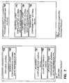
- FIG. 7 illustrates preferred embodiments of two computer program products 101, 102 for cache adjustment according to the present invention.
- Computer program products 101 and 102 complement each other when running on two cache computers 901, 902 with similar functionality.
- computer program 101 is running on cache computer 901
- complementary computer program 102 is running on complementary cache computer 902.
- each cache computer 900, 901, 902, 905 and 906 runs a first computer program that is functionally equivalent to CPP 101 and a second computer program that is functionally equivalent to CPP 102. This allows each cache computer to act as sender and as receiver according to the invention.
- the arrangement of pluralities 710-790 of instructions (also referred to as "coding sections" in the following) of computer program products 101, 102 indicates the temporal order in which the coding sections are processed, when both programs are communicating.
- the coding sections at the top are processed first and the ones at the bottom are processed last.
- Coding sections 710 and 760 can be processed substantially simultaneously.
- the coding sections are processed in the following order: 720, 770, 780, 790,730, 740, 750.
- Computer program product 101 has pluralities 710, 720, 730, 740, 750 of instructions (coding sections) for causing processor 911 of cache computer 901 to execute steps for adjusting cache 921-1 of cache computer 901.
- Coding section 710 provides journal 111.
- Coding section 720 sends 420 at least a representation 121-2 of a previous latest journal entry 112-11 of complementary journal 112 of complementary cache computer 902.
- previous latest journal entry 112-11 refers to origin computer 903;
- Coding section 730 receives in journal 111 at least one journal entry 112-10 from complementary journal 112.
- the at least one journal entry 112-10 was generated later than previous latest journal entry 112-11 and, in the example, indicates a modification of object 191 on origin computer 903.
- Coding section 740 adjusts 450 cache 921-1 according to journal 111. That is, in case a journal entry of journal 111 indicates that an object (e.g. 191*), which is stored in cache 921-1, has become obsolete because it was modified after being loaded into the cache 921-1, cache computer 901 deletes the object from its cache 921-1.
- object e.g. 191*
- Coding section 750 updates 460 the at least one representation 121-2 on cache computer 901 according to the journal 111.
- a representation of latest journal entry 111-10 referring to third computer 903 replaces representation 121-2.
- Complementary computer program product 102 has coding sections 760, 770, 780, 790 to execute steps for transmitting complementary journal entries to cache computer 901.
- Coding section 760 provides complementary journal 112.
- a journal entry 112-10 of complementary journal 112 has a unique key 112-1 and the journal entry 112-10 indicates a modification of an object (191) on origin computer 903.
- Coding section 770 receives at least a representation 121-2 of a previous latest journal entry 112-11 of complementary journal 112.
- previous latest journal entry 112-11 refers to origin computer 903.
- Coding section 780 compares 430 the at least one representation 121-2 with a comparable portion 112-1 of complementary journal 112.
- Coding section 790 transmits 440 from complementary journal 112 to journal 111 of cache computer 901 at least each journal entry 112-10 that refers to the origin computer 903 and that is newer than previous latest journal entry 112-11.
- Computer program product 101 comprises further instructions for:
- Complementary computer program product 102 comprises further instructions for:
- the present invention was already described as computer system 999 in FIGS. 2 , 3 and 6 .
- computer system 999 is summarized in the following.
- Computer system 999 comprises at least origin computer 903, first cache computer 901 and at least second cache computer 902.
- Origin computer 903 is for storing and modifying objects.
- First cache computer 901 is for:
- Second cache computer 902 is for:
- First cache computer 901 further is for:
- Second cache computer 902 further is for:
Landscapes
- Engineering & Computer Science (AREA)
- Databases & Information Systems (AREA)
- Theoretical Computer Science (AREA)
- Data Mining & Analysis (AREA)
- Physics & Mathematics (AREA)
- General Engineering & Computer Science (AREA)
- General Physics & Mathematics (AREA)
- Information Retrieval, Db Structures And Fs Structures Therefor (AREA)
- Memory System Of A Hierarchy Structure (AREA)
- Multi Processors (AREA)
Claims (13)
- Computerimplementiertes Verfahren (400), beinhaltend einen ersten Cachecomputer (901) mit einem ersten Cache (921-1) und wenigstens einen zweiten Cachecomputer (902) mit einem zweiten Cache (922-1); wobei das Verfahren (400) die nachfolgenden Schritte umfasst:Bereitstellen (410) eines ersten Journals (111) auf dem ersten Cachecomputer (901) und eines zweiten Journals (112) auf dem zweiten Cachecomputer (902), einer ersten Zusammenfassungsmatrix (141) des ersten Computers (901) und einer zweiten Zusammenfassungsmatrix (142) des zweiten Computers (902), wobei beide Zusammenfassungsmatrizen (141, 142) für jeden Cachecomputer in dem Netzwerk einen Identifizierer für den Cachecomputer und eine Inhaltszusammenfassung des Cachecomputers umfassen, wobei die Inhaltszusammenfassung eine Abfolge einer Mehrzahl von Bitmustern auf dem Cachecomputer ist, wobei jedes Bitmuster eine Darstellung eines Objektes ist, das in dem Cache des Cachecomputers gespeichert ist, und wobei wenigstens ein zweiter Journaleintrag (112-10) eine vorherige Abänderung eines Objektes (191) auf einem Ausgangscomputer (903) anzeigt;Empfangen (413) einer Anforderung (190-1) für ein Objekt (190) aus der Speicherung in dem zweiten Cache (922-1) auf dem ersten Cachecomputer (901);über die erste Zusammenfassungsmatrix (141) erfolgendes Identifizieren des zweiten Computers (902) als Lieferant des Objektes (190);von dem ersten Cachecomputer (901) an den zweiten Cachecomputer (902) erfolgendes Senden (420) eines Synchronisationsvektors (121), wobei der Synchronisationsvektor (121) wenigstens eine Synchronisationsmarke (121-2) umfasst, die eine Darstellung eines vorherigen letzten zweiten Journaleintrages (112-11) zu der Zeit der letzten Synchronisation zwischen dem ersten Cachecomputer (901) und dem zweiten Cachecomputer (902) speichert, wobei der vorherige letzte Journaleintrag (112-11) Bezug auf den Ausgangscomputer (903) nimmt, und Senden der Anforderung (190-1) für das Objekt (190) von dem ersten Cachecomputer (901) an den zweiten Cachecomputer (902);Vergleichen (430) der wenigstens einen Synchronisationsmarke (121-2) mit einem vergleichbaren Abschnitt (112-1) des zweiten Journals (112), wobei der vergleichbare Abschnitt wenigstens einen Schlüssel des wenigstens einen zweiten Journaleintrages (112-10) identifiziert;für den Fall, dass das zweite Journal (112) einen aktuellen letzten zweiten Journaleintrag (112-10) mit Bezugnahme auf den Ausgangscomputer (903), der neuer als der vorherige letzte zweite Journaleintrag (112-11) ist, aufweist, von dem zweiten Journal (112) an das erste Journal (111) erfolgendes Übertragen (440) wenigstens jedes zweiten Journaleintrages (112-10), der neuer als der vorherige letzte zweite Journaleintrag (112-11) ist und der auf den Ausgangscomputer (903) Bezug nimmt, und Hinzufügen des zweiten Journaleintrages (112-10) als erster Journaleintrag (111-10) zu dem ersten Journal (111), wobei der zweite Computer (902) den zweiten Cache (922-1) verwendet und der Schritt des Übertragens (440) des Weiteren das Objekt (190) von dem zweiten Cache (922-1) an den ersten Cache (921-1) des ersten Computers (901) überträgt;Anpassen (450) des ersten Cache (921-1) entsprechend dem ersten Journal (111) durch Löschen eines veralteten Objektes (191*) in dem ersten Cache (921-1), wobei das veraltete Objekt (191*) durch den ersten Journaleintrag (111-10) identifiziert ist; undAktualisieren (460) der wenigstens einen Synchronisationsmarke (121-2) auf dem ersten Cachecomputer (901) mit einer Darstellung des entsprechenden letzten ersten Journaleintrages (111-10), der eine Kopie des aktuellen letzten zweiten Journaleintrages (112-10) ist.
- Verfahren (400) nach Anspruch 1, wobei der Schritt des Aktualisierens (460) des Weiteren die erste Zusammenfassungsmatrix (141) aktualisiert.
- Verfahren (400) nach Anspruch 2, des Weiteren umfassend den nachfolgenden weiteren Schritt:Synchronisieren (465) der ersten Zusammenfassungsmatrix (141) mit der zweiten Zusammenfassungsmatrix (142).
- Computerprogrammerzeugnis (101) mit Mehrzahlen von Anweisungen zum Veranlassen eines Prozessors (911) eines ersten Cachecomputers (901), Schritte zum Anpassen eines ersten Cache (921-1) des ersten Cachecomputers (901) auszuführen, wobei das Computerprogrammerzeugnis (101) die nachfolgenden Mehrzahlen von Anweisungen umfasst:eine Mehrzahl (710) zum Bereitstellen eines ersten Journals (111) und einer Zusammenfassungsmatrix (141) auf dem ersten Cachecomputer (901), wobei die Zusammenfassungsmatrix (141) für jeden Cachecomputer in dem Netzwerk einen Identifizierer für den Cachecomputer und eine Inhaltszusammenfassung des Cachecomputers umfasst, wobei die Inhaltszusammenfassung eine Abfolge einer Mehrzahl von Bitmustern auf dem Cachecomputer ist, wobei jedes Bitmuster eine Darstellung eines Objektes ist, das in dem Cache des Cachecomputers gespeichert ist;eine Mehrzahl zum Empfangen (413) einer Anforderung (190-1) für ein Objekt (190) auf dem ersten Cachecomputer (901) und zum über die Zusammenfassungsmatrix (141) erfolgenden Identifizieren (416) eines zweiten Cachecomputers (902) als Lieferant des Objektes (190);eine Mehrzahl (720) zum Senden (420) eines Synchronisationsvektors (121), wobei der Synchronisationsvektor (121) wenigstens eine Synchronisationsmarke (121-2) umfasst, die eine Darstellung eines vorherigen letzten Journaleintrages (112-11) eines komplementären Journals (112) eines zweiten Cachecomputers (902) - wobei auf das komplementäre Journal in Folge als das zweite Journal (112) Bezug genommen wird - zu der Zeit der letzten Synchronisation zwischen dem ersten Cachecomputer (901) und dem zweiten Cachecomputer (902) speichert, wobei der vorherige letzte zweite Journaleintrag (112-11) auf einen Ausgangscomputer (903) Bezug nimmt, und zum Senden der Anforderung (190-1) für das Objekt (190) von dem ersten Cachecomputer (901) an den zweiten Cachecomputer (902);eine Mehrzahl (730) zum in dem ersten Journal (111) erfolgenden Empfangen wenigstens eines zweiten Journaleintrages (112-10) von dem zweiten Journal (112), wobei der wenigstens eine zweite Journaleintrag (112-10) später als der vorherige letzte zweite Journaleintrag (112-11) erzeugt worden ist und eine Abänderung eines Objektes (191) auf dem Ausgangscomputer (903) anzeigt und wobei der wenigstens eine zweite Journaleintrag (112-10) als erster Journaleintrag (111-10) hinzugefügt wird;eine Mehrzahl (740) zum Anpassen (450) des ersten Cache (921-1) entsprechend dem ersten Journal (111) durch Löschen eines veralteten Objektes (191*) in dem ersten Cache (921-1), wobei das veraltete Objekt (191*) durch den ersten Journaleintrag (111-10) identifiziert ist;eine Mehrzahl (750) zum Aktualisieren (460) der wenigstens einen Synchronisationsmarke (121-2) auf dem ersten Cachecomputer (901) mit einer Darstellung des entsprechenden letzten ersten Journaleintrages (111-10), der eine Kopie des aktuellen letzten zweiten Journaleintrages (112-10) ist.
- Computerprogrammerzeugnis (102) mit Mehrzahlen von Anweisungen zum Veranlassen eines Prozessors (912) eines zweiten Cachecomputers (902) mit einem zweiten Cache (922-1), Schritte zum Übertragen von Journaleinträgen an einen ersten Cachecomputer (901) mit einem ersten Cache (921-1) auszuführen; wobei das Computerprogrammerzeugnis (102) die nachfolgenden Mehrzahlen von Anweisungen umfasst:eine Mehrzahl (760) zum Bereitstellen eines Journals (112) des zweiten Cachecomputers - wobei auf das Journal in Folge als das zweite Journal (112) Bezug genommen wird -, wobei ein Journaleintrag (112-10) des zweiten Journals (112) einen eindeutigen Schlüssel (112-1) aufweist und der Journaleintrag (112-10) eine Abänderung betreffend ein Objekt (191) auf einem Ausgangscomputer (903) und eine Zusammenfassungsmatrix (142) auf dem zweiten Cachecomputer (902) anzeigt, wobei die Zusammenfassungsmatrix (142) für jeden Cachecomputer in dem Netzwerk einen Identifizierer des Cachecomputers und eine Inhaltszusammenfassung des Cachecomputers umfasst, wobei die Inhaltszusammenfassung eine Abfolge einer Mehrzahl von Bitmustern auf dem Cachecomputer ist, wobei jedes Bitmuster eine Darstellung eines Objektes ist, das in dem Cache des Cachecomputers gespeichert ist;eine Mehrzahl (770) zum Empfangen eines Synchronisationsvektors, der wenigstens eine Synchronisationsmarke (121-2) umfasst, die eine Darstellung eines vorherigen letzten zweiten Journaleintrages (112-11) zu der Zeit der letzten Synchronisation zwischen dem ersten Cachecomputer und dem zweiten Cachecomputer speichert, wobei der vorherige letzte zweite Journaleintrag (121-11) auf den Ausgangscomputer (903) Bezug nimmt;eine Mehrzahl (780) zum Vergleichen (430) der wenigstens einen Synchronisationsmarke (121-2) mit einem vergleichbaren Abschnitt (112-1) des zweiten Journals (112), wobei der vergleichbare Abschnitt wenigstens einen Schlüssel des wenigstens einen zweiten Journaleintrages (112-10) identifiziert;eine Mehrzahl (790) zum von dem zweiten Journal (112) an ein komplementäres Journal (111) des ersten Cachecomputers (901) erfolgenden Übertragen - wobei auf das komplementäre Journal in Folge als das erste Journal (111) Bezug genommen wird - wenigstens jedes zweiten Journaleintrages (112-10), der auf den Ausgangscomputer (903) Bezug nimmt und der neuer als der vorherige letzte zweite Journaleintrag (112-11) ist; undeine Mehrzahl zum Empfangen einer Anforderung (190-1) für ein Objekt (190), das in dem zweiten Cache (922-2) des zweiten Cachecomputers (902) gespeichert ist, und zum Übertragen des weiteren Objektes (190) von dem zweiten Cache (922-2) an den ersten Cache (921-1) des ersten Computers (901).
- Computerprogrammerzeugnis (101) nach Anspruch 4, des Weiteren umfassend Anweisungen zum Empfangen des weiteren Objektes (190) von dem zweiten Cache (922-1) des zweiten Cachecomputers (902).
- Computerprogrammerzeugnis (101) nach Anspruch 6, des Weiteren umfassend eine Anweisung zum Speichern einer Kopie (190*) des weiteren Objektes (190) in dem ersten Cache (921-1) des ersten Cachecomputers (901).
- Computerprogrammerzeugnis (101) nach Anspruch 7, des Weiteren umfassend Anweisungen zum Aktualisieren der Zusammenfassungsmatrix (141) entsprechend dem ersten Cache (921-1) des ersten Cachecomputers (901).
- Computerprogrammerzeugnis (101) nach Anspruch 8, des Weiteren umfassend Anweisungen zum Senden der Zusammenfassungsmatrix (141) an den zweiten Cachecomputer 902).
- Computerprogrammerzeugnis (102) nach Anspruch 5, des Weiteren umfassend Anweisungen zum Empfangen einer komplementären Zusammenfassungsmatrix (141) des ersten Cachecomputers (901) und zum Synchronisieren der Zusammenfassungsmatrix (142) mit der komplementären Zusammenfassungsmatrix (141).
- Computersystem (999), umfassend wenigstens einen Ausgangscomputer (903), einen ersten Cachecomputer (901) und wenigstens einen zweiten Cachecomputer (902);
wobei der Ausgangscomputer (903) dem Speichern und Abändern von Objekten dient;
wobei der erste Cachecomputer (901) betreibbar ist zum:Bereitstellen eines ersten Journals (111) und einer ersten Zusammenfassungsmatrix (141), wobei die erste Zusammenfassungsmatrix (141) für jeden Cachecomputer in dem Netzwerk einen Identifizierer für den Cachecomputer und eine Zusammenfassungsmatrix des Cachecomputers umfasst, wobei die Inhaltszusammenfassung eine Abfolge einer Mehrzahl von Bitmustern auf dem Cachecomputer ist, wobei jedes Bitmuster eine Darstellung eines Objektes ist, das in dem Cache des Cachecomputers gespeichert ist;Empfangen (413) einer Anforderung (190-1) für ein Objekt (190) und über die erste Zusammenfassungsmatrix (141) erfolgendes Identifizieren (416) des zweiten Cachecomputers (902) als Lieferant des Objektes (190);an den zweiten Cachecomputer (902) erfolgendes Senden (420) eines Synchronisationsvektors (121), wobei der Synchronisationsvektor (121) wenigstens eine Synchronisationsmarke (121-2) umfasst, die eine Darstellung eines vorherigen letzten Journaleintrages (112-11) eines Journals (112) des zweiten Cachecomputers - wobei auf das Journal in Folge als das zweite Journal (112) Bezug genommen wird - zu der Zeit der letzten Synchronisation zwischen dem ersten Cachecomputer (901) und dem zweiten Cachecomputer (902) speichert, wobei der vorherige letzte zweite Journaleintrag (112-11) auf den Ausgangscomputer (903) Bezug nimmt, und Senden der Anforderung (190-1) für das Objekt (190) an den zweiten Cachecomputer (902);in dem ersten Journal (111) erfolgendes Empfangen wenigstens eines zweiten Journaleintrages (112-10) von dem zweiten Journal (112) des zweiten Cachecomputers (902), der neuer als der vorherige letzte zweite Journaleintrag (112-10) ist und der auf den Ausgangscomputer (903) Bezug nimmt, wobei der wenigstens eine zweite Journaleintrag (112-10) als erster Journaleintrag (110-10) zu dem ersten Journal (111) hinzugefügt wird;Anpassen (450) eines ersten Cache (921-1) des ersten Cachecomputers (901) entsprechend dem ersten Journal (111) durch Löschen eines veralteten Objektes (191*) in dem ersten Cache (921-1), wobei das veraltete Objekt (191*) durch den ersten Journaleintrag (111-10) identifiziert ist; undAktualisieren (460) der wenigstens einen Synchronisationsmarke (121-2) auf dem ersten Cachecomputer (901) mit einer Darstellung des entsprechenden letzten ersten Journaleintrages (111-10), der eine Kopie des aktuellen letzten zweiten Journaleintrages (112-10) ist;wobei der zweite Cachecomputer (902) betreibbar ist zum:Bereitstellen des zweiten Journals (112), wobei der Journaleintrag (112-10) des zweiten Journals (112) einen eindeutigen Schlüssel (112-1) aufweist und der Journaleintrag (112-10) eine Abänderung betreffend ein Objekt auf dem Ausgangscomputer (903) und eine zweite Zusammenfassungsmatrix (142) anzeigt, wobei die zweite Zusammenfassungsmatrix (142) für jeden Cachecomputer in dem Netzwerk einen Identifizierer für den Cachecomputer und eine Inhaltszusammenfassung des Cachecomputers umfasst, wobei die Inhaltszusammenfassung eine Abfolge einer Mehrzahl von Bitmustern auf dem Cachecomputer ist, wobei jedes Bitmuster eine Darstellung eines Objektes ist, das in dem Cache des Cachecomputers gespeichert ist;Empfangen des Synchronisationsvektors, der die wenigstens eine Synchronisationsmarke (121-2) umfasst;Vergleichen der wenigstens einen Synchronisationsmarke (121-2) mit einem vergleichbaren Abschnitt (112-1) des zweiten Journals (112), wobei der vergleichbare Abschnitt wenigstens einen Schlüssel des wenigstens einen zweiten Journaleintrages (112-10) identifiziert;von dem zweiten Journal (112) an das erste Journal (111) erfolgendes Übertragen (440) wenigstens jedes zweiten Journaleintrages (112-10), der auf den Ausgangscomputer (903) Bezug nimmt und der neuer als der vorherige letzte Journaleintrag (112-11) ist;Empfangen einer Anforderung (190-1) für das Objekt (190), das in dem zweiten Cache (922-1) des zweiten Cachecomputers (902) gespeichert ist; und Übertragen des Objektes (190) an den ersten Cache (921-1). - Computersystem (999) nach Anspruch 11, wobei der erste Cachecomputer (901) des Weiteren betreibbar ist zum:Empfangen des Objektes (190);Speichern einer Kopie (190*) des Objektes (190) in dem ersten Cache (921-1);Aktualisieren der ersten Zusammenfassungsmatrix (141); undSenden der ersten Zusammenfassungsmatrix (141) an den zweiten Cachecomputer (902).
- Computersystem (999) nach Anspruch 12, wobei der zweite Cachecomputer (902) des Weiteren betreibbar ist zum:Empfangen einer ersten Zusammenfassungsmatrix (141) von dem ersten Cachecomputer (901); undSynchronisieren (465) der ersten Zusammenfassungsmatrix (141) mit der zweiten Zusammenfassungsmatrix (142).
Priority Applications (4)
| Application Number | Priority Date | Filing Date | Title |
|---|---|---|---|
| AT01123095T ATE404925T1 (de) | 2001-09-27 | 2001-09-27 | Verfahren und vorrichtung zur aktualisierung des cachespeichers |
| EP01123095A EP1298537B1 (de) | 2001-09-27 | 2001-09-27 | Verfahren und Vorrichtung zur Aktualisierung des Cachespeichers |
| DE60135342T DE60135342D1 (de) | 2001-09-27 | 2001-09-27 | Verfahren und Vorrichtung zur Aktualisierung des Cachespeichers |
| US10/259,996 US6820114B2 (en) | 2001-09-27 | 2002-09-27 | Identifying object suppliers in a network |
Applications Claiming Priority (1)
| Application Number | Priority Date | Filing Date | Title |
|---|---|---|---|
| EP01123095A EP1298537B1 (de) | 2001-09-27 | 2001-09-27 | Verfahren und Vorrichtung zur Aktualisierung des Cachespeichers |
Publications (2)
| Publication Number | Publication Date |
|---|---|
| EP1298537A1 EP1298537A1 (de) | 2003-04-02 |
| EP1298537B1 true EP1298537B1 (de) | 2008-08-13 |
Family
ID=8178739
Family Applications (1)
| Application Number | Title | Priority Date | Filing Date |
|---|---|---|---|
| EP01123095A Expired - Lifetime EP1298537B1 (de) | 2001-09-27 | 2001-09-27 | Verfahren und Vorrichtung zur Aktualisierung des Cachespeichers |
Country Status (3)
| Country | Link |
|---|---|
| EP (1) | EP1298537B1 (de) |
| AT (1) | ATE404925T1 (de) |
| DE (1) | DE60135342D1 (de) |
Families Citing this family (2)
| Publication number | Priority date | Publication date | Assignee | Title |
|---|---|---|---|---|
| EP1298538B1 (de) * | 2001-09-27 | 2012-05-30 | Sap Ag | Verfahren und Vorrichtung zur Identifizierung von Bereitstellen von Objekten in einem Computernetzwerk |
| US7591019B1 (en) | 2009-04-01 | 2009-09-15 | Kaspersky Lab, Zao | Method and system for optimization of anti-virus scan |
Family Cites Families (2)
| Publication number | Priority date | Publication date | Assignee | Title |
|---|---|---|---|---|
| US6098078A (en) * | 1995-12-29 | 2000-08-01 | Lucent Technologies Inc. | Maintaining consistency of database replicas |
| GB9812221D0 (en) * | 1998-06-05 | 1998-08-05 | British Telecomm | Distributed database system |
-
2001
- 2001-09-27 EP EP01123095A patent/EP1298537B1/de not_active Expired - Lifetime
- 2001-09-27 AT AT01123095T patent/ATE404925T1/de not_active IP Right Cessation
- 2001-09-27 DE DE60135342T patent/DE60135342D1/de not_active Expired - Lifetime
Non-Patent Citations (2)
| Title |
|---|
| DUANE WESSELS: "Web Caching", June 2001, O'REILLY, ISBN: 1-56592-536-X * |
| TEWARI R. ET AL: "Design considerations for distributed caching on the Internet", DISTRIBUTED COMPUTING SYSTEMS, 1999. PROCEEDINGS. 19TH IEEE INTERNATIONAL CONFERENCE ON AUSTIN, TX, USA, 31 May 1999 (1999-05-31), LOS ALAMITOS, CA, USA, pages 273 - 284, XP002933076 * |
Also Published As
| Publication number | Publication date |
|---|---|
| ATE404925T1 (de) | 2008-08-15 |
| DE60135342D1 (de) | 2008-09-25 |
| EP1298537A1 (de) | 2003-04-02 |
Similar Documents
| Publication | Publication Date | Title |
|---|---|---|
| US7539778B2 (en) | Method for a caching mechanism for a central synchronization server | |
| US6389460B1 (en) | Method and apparatus for efficient storage and retrieval of objects in and from an object storage device | |
| US7269608B2 (en) | Apparatus and methods for caching objects using main memory and persistent memory | |
| KR100462839B1 (ko) | 모바일 환경에서의 이동 클라이언트와 서버간의 데이터동기화 및 갱신 충돌 해결 방법 | |
| US20040064650A1 (en) | Method, system, and program for maintaining data in distributed caches | |
| US6584548B1 (en) | Method and apparatus for invalidating data in a cache | |
| US6618751B1 (en) | Systems and methods for publishing data with expiration times | |
| JP4579501B2 (ja) | アプリケーションサーバおよびアプリケーションプログラム | |
| US6557076B1 (en) | Method and apparatus for aggressively rendering data in a data processing system | |
| CN102985921A (zh) | 在具有电子资源数据库的客户端装置中高速缓存电子文档资源 | |
| JP2002511616A (ja) | 高性能オブジェクト・キャッシュ | |
| WO1999022316A1 (en) | Shared cache parsing and pre-fetch | |
| US20020092012A1 (en) | Smart-caching system and method | |
| US20200019514A1 (en) | Client-side caching for deduplication data protection and storage systems | |
| CN108897868A (zh) | 基于触发器的缓存同步方法及装置、计算设备及存储介质 | |
| US6820114B2 (en) | Identifying object suppliers in a network | |
| JP2006286013A (ja) | オブジェクト状態転送方法,オブジェクト状態転送装置およびオブジェクト状態転送プログラム並びにそのプログラムの記録媒体 | |
| US20020184441A1 (en) | Apparatus and methods for caching objects using main memory and persistent memory | |
| EP1298537A1 (de) | Verfahren und Vorrichtung zur Aktualisierung des Cachespeichers | |
| EP1217805A1 (de) | Verfahren und Vorrichtung zum Ersetzen von Datenübertragungsanforderungsformeln | |
| EP1298538B1 (de) | Verfahren und Vorrichtung zur Identifizierung von Bereitstellen von Objekten in einem Computernetzwerk | |
| KR20200144768A (ko) | 다중 웹서버 환경의 공용자원 동기화 시스템 | |
| JP2000137689A (ja) | 共用データキャッシュ処理方法及びその実施装置並びにその処理プログラムを記録した媒体 | |
| KR100532340B1 (ko) | 페이지 구축기 툴을 사용하여 메세지를 발행하는 방법 및 시스템과 컴퓨터 판독가능한 기록 매체 | |
| JP2013050864A (ja) | 情報処理システム、情報処理方法および情報処理プログラム |
Legal Events
| Date | Code | Title | Description |
|---|---|---|---|
| PUAI | Public reference made under article 153(3) epc to a published international application that has entered the european phase |
Free format text: ORIGINAL CODE: 0009012 |
|
| AK | Designated contracting states |
Kind code of ref document: A1 Designated state(s): AT BE CH CY DE DK ES FI FR GB GR IE IT LI LU MC NL PT SE TR Designated state(s): AT BE CH CY DE DK ES FI FR GB GR IE IT LI LU MC NL PT SE TR |
|
| AX | Request for extension of the european patent |
Extension state: AL LT LV MK RO SI |
|
| 17P | Request for examination filed |
Effective date: 20031002 |
|
| AKX | Designation fees paid |
Designated state(s): AT BE CH CY DE DK ES FI FR GB GR IE IT LI LU MC NL PT SE TR |
|
| 17Q | First examination report despatched |
Effective date: 20040720 |
|
| RAP1 | Party data changed (applicant data changed or rights of an application transferred) |
Owner name: SAP AG |
|
| GRAP | Despatch of communication of intention to grant a patent |
Free format text: ORIGINAL CODE: EPIDOSNIGR1 |
|
| GRAS | Grant fee paid |
Free format text: ORIGINAL CODE: EPIDOSNIGR3 |
|
| GRAA | (expected) grant |
Free format text: ORIGINAL CODE: 0009210 |
|
| AK | Designated contracting states |
Kind code of ref document: B1 Designated state(s): AT BE CH CY DE DK ES FI FR GB GR IE IT LI LU MC NL PT SE TR |
|
| REG | Reference to a national code |
Ref country code: GB Ref legal event code: FG4D |
|
| REG | Reference to a national code |
Ref country code: CH Ref legal event code: EP |
|
| REG | Reference to a national code |
Ref country code: IE Ref legal event code: FG4D |
|
| REF | Corresponds to: |
Ref document number: 60135342 Country of ref document: DE Date of ref document: 20080925 Kind code of ref document: P |
|
| PG25 | Lapsed in a contracting state [announced via postgrant information from national office to epo] |
Ref country code: NL Free format text: LAPSE BECAUSE OF FAILURE TO SUBMIT A TRANSLATION OF THE DESCRIPTION OR TO PAY THE FEE WITHIN THE PRESCRIBED TIME-LIMIT Effective date: 20080813 Ref country code: ES Free format text: LAPSE BECAUSE OF FAILURE TO SUBMIT A TRANSLATION OF THE DESCRIPTION OR TO PAY THE FEE WITHIN THE PRESCRIBED TIME-LIMIT Effective date: 20081124 |
|
| PG25 | Lapsed in a contracting state [announced via postgrant information from national office to epo] |
Ref country code: FI Free format text: LAPSE BECAUSE OF FAILURE TO SUBMIT A TRANSLATION OF THE DESCRIPTION OR TO PAY THE FEE WITHIN THE PRESCRIBED TIME-LIMIT Effective date: 20080813 Ref country code: AT Free format text: LAPSE BECAUSE OF FAILURE TO SUBMIT A TRANSLATION OF THE DESCRIPTION OR TO PAY THE FEE WITHIN THE PRESCRIBED TIME-LIMIT Effective date: 20080813 |
|
| PG25 | Lapsed in a contracting state [announced via postgrant information from national office to epo] |
Ref country code: BE Free format text: LAPSE BECAUSE OF FAILURE TO SUBMIT A TRANSLATION OF THE DESCRIPTION OR TO PAY THE FEE WITHIN THE PRESCRIBED TIME-LIMIT Effective date: 20080813 |
|
| PG25 | Lapsed in a contracting state [announced via postgrant information from national office to epo] |
Ref country code: MC Free format text: LAPSE BECAUSE OF NON-PAYMENT OF DUE FEES Effective date: 20080930 Ref country code: DK Free format text: LAPSE BECAUSE OF FAILURE TO SUBMIT A TRANSLATION OF THE DESCRIPTION OR TO PAY THE FEE WITHIN THE PRESCRIBED TIME-LIMIT Effective date: 20080813 |
|
| REG | Reference to a national code |
Ref country code: CH Ref legal event code: PL |
|
| PG25 | Lapsed in a contracting state [announced via postgrant information from national office to epo] |
Ref country code: PT Free format text: LAPSE BECAUSE OF FAILURE TO SUBMIT A TRANSLATION OF THE DESCRIPTION OR TO PAY THE FEE WITHIN THE PRESCRIBED TIME-LIMIT Effective date: 20090113 |
|
| PLBE | No opposition filed within time limit |
Free format text: ORIGINAL CODE: 0009261 |
|
| STAA | Information on the status of an ep patent application or granted ep patent |
Free format text: STATUS: NO OPPOSITION FILED WITHIN TIME LIMIT |
|
| 26N | No opposition filed |
Effective date: 20090514 |
|
| PG25 | Lapsed in a contracting state [announced via postgrant information from national office to epo] |
Ref country code: IE Free format text: LAPSE BECAUSE OF NON-PAYMENT OF DUE FEES Effective date: 20080927 |
|
| PG25 | Lapsed in a contracting state [announced via postgrant information from national office to epo] |
Ref country code: IT Free format text: LAPSE BECAUSE OF FAILURE TO SUBMIT A TRANSLATION OF THE DESCRIPTION OR TO PAY THE FEE WITHIN THE PRESCRIBED TIME-LIMIT Effective date: 20080813 |
|
| PG25 | Lapsed in a contracting state [announced via postgrant information from national office to epo] |
Ref country code: LI Free format text: LAPSE BECAUSE OF NON-PAYMENT OF DUE FEES Effective date: 20080930 Ref country code: CH Free format text: LAPSE BECAUSE OF NON-PAYMENT OF DUE FEES Effective date: 20080930 |
|
| PG25 | Lapsed in a contracting state [announced via postgrant information from national office to epo] |
Ref country code: SE Free format text: LAPSE BECAUSE OF FAILURE TO SUBMIT A TRANSLATION OF THE DESCRIPTION OR TO PAY THE FEE WITHIN THE PRESCRIBED TIME-LIMIT Effective date: 20081113 |
|
| PG25 | Lapsed in a contracting state [announced via postgrant information from national office to epo] |
Ref country code: LU Free format text: LAPSE BECAUSE OF NON-PAYMENT OF DUE FEES Effective date: 20080927 Ref country code: CY Free format text: LAPSE BECAUSE OF FAILURE TO SUBMIT A TRANSLATION OF THE DESCRIPTION OR TO PAY THE FEE WITHIN THE PRESCRIBED TIME-LIMIT Effective date: 20080813 |
|
| PG25 | Lapsed in a contracting state [announced via postgrant information from national office to epo] |
Ref country code: TR Free format text: LAPSE BECAUSE OF FAILURE TO SUBMIT A TRANSLATION OF THE DESCRIPTION OR TO PAY THE FEE WITHIN THE PRESCRIBED TIME-LIMIT Effective date: 20080813 |
|
| PG25 | Lapsed in a contracting state [announced via postgrant information from national office to epo] |
Ref country code: GR Free format text: LAPSE BECAUSE OF FAILURE TO SUBMIT A TRANSLATION OF THE DESCRIPTION OR TO PAY THE FEE WITHIN THE PRESCRIBED TIME-LIMIT Effective date: 20081114 |
|
| REG | Reference to a national code |
Ref country code: DE Ref legal event code: R082 Ref document number: 60135342 Country of ref document: DE Representative=s name: MUELLER-BORE & PARTNER PATENTANWAELTE PARTG MB, DE |
|
| REG | Reference to a national code |
Ref country code: DE Ref legal event code: R082 Ref document number: 60135342 Country of ref document: DE Representative=s name: MUELLER-BORE & PARTNER PATENTANWAELTE PARTG MB, DE Effective date: 20141210 Ref country code: DE Ref legal event code: R081 Ref document number: 60135342 Country of ref document: DE Owner name: SAP SE, DE Free format text: FORMER OWNER: SAP AG, 69190 WALLDORF, DE Effective date: 20141210 |
|
| REG | Reference to a national code |
Ref country code: FR Ref legal event code: PLFP Year of fee payment: 16 |
|
| REG | Reference to a national code |
Ref country code: FR Ref legal event code: PLFP Year of fee payment: 17 |
|
| REG | Reference to a national code |
Ref country code: FR Ref legal event code: PLFP Year of fee payment: 18 |
|
| REG | Reference to a national code |
Ref country code: DE Ref legal event code: R079 Ref document number: 60135342 Country of ref document: DE Free format text: PREVIOUS MAIN CLASS: G06F0017300000 Ipc: G06F0016000000 |
|
| PGFP | Annual fee paid to national office [announced via postgrant information from national office to epo] |
Ref country code: GB Payment date: 20200922 Year of fee payment: 20 Ref country code: DE Payment date: 20200925 Year of fee payment: 20 Ref country code: FR Payment date: 20200914 Year of fee payment: 20 |
|
| REG | Reference to a national code |
Ref country code: DE Ref legal event code: R071 Ref document number: 60135342 Country of ref document: DE |
|
| REG | Reference to a national code |
Ref country code: GB Ref legal event code: PE20 Expiry date: 20210926 |
|
| PG25 | Lapsed in a contracting state [announced via postgrant information from national office to epo] |
Ref country code: GB Free format text: LAPSE BECAUSE OF EXPIRATION OF PROTECTION Effective date: 20210926 |