EP1298464A2 - Fibre optique silice à double gaine polymere - Google Patents
Fibre optique silice à double gaine polymere Download PDFInfo
- Publication number
- EP1298464A2 EP1298464A2 EP02292183A EP02292183A EP1298464A2 EP 1298464 A2 EP1298464 A2 EP 1298464A2 EP 02292183 A EP02292183 A EP 02292183A EP 02292183 A EP02292183 A EP 02292183A EP 1298464 A2 EP1298464 A2 EP 1298464A2
- Authority
- EP
- European Patent Office
- Prior art keywords
- optical
- sheath
- core
- refractive index
- polymer
- Prior art date
- Legal status (The legal status is an assumption and is not a legal conclusion. Google has not performed a legal analysis and makes no representation as to the accuracy of the status listed.)
- Granted
Links
Images
Classifications
-
- G—PHYSICS
- G02—OPTICS
- G02B—OPTICAL ELEMENTS, SYSTEMS OR APPARATUS
- G02B6/00—Light guides; Structural details of arrangements comprising light guides and other optical elements, e.g. couplings
- G02B6/02—Optical fibres with cladding with or without a coating
- G02B6/036—Optical fibres with cladding with or without a coating core or cladding comprising multiple layers
- G02B6/03616—Optical fibres characterised both by the number of different refractive index layers around the central core segment, i.e. around the innermost high index core layer, and their relative refractive index difference
- G02B6/03622—Optical fibres characterised both by the number of different refractive index layers around the central core segment, i.e. around the innermost high index core layer, and their relative refractive index difference having 2 layers only
-
- G—PHYSICS
- G02—OPTICS
- G02B—OPTICAL ELEMENTS, SYSTEMS OR APPARATUS
- G02B6/00—Light guides; Structural details of arrangements comprising light guides and other optical elements, e.g. couplings
- G02B6/02—Optical fibres with cladding with or without a coating
- G02B6/02033—Core or cladding made from organic material, e.g. polymeric material
Definitions
- the present invention relates to the field of optical fibers used for transmission and / or amplification of optical signals.
- An optical fiber is conventionally made up of a core surrounded by an optical sheath and protected by a coating.
- the heart has the function of transmitting, and possibly amplifying, an optical signal
- the optical sheath has the function of confining the optical signal in the heart.
- the refractive indices of the core n 1 and of the cladding n 2 are such that n 1 > n 2 .
- the optical fibers used in transmission can consist of a single-mode core, for propagation of a single optical signal, or multimode for the simultaneous propagation of several optical signals.
- the character singlemode or multimode of an optical fiber depends essentially on its heart diameter.
- the multimode transmission fibers are advantageously used for short distance applications at medium flow, i.e. narrow bandwidth.
- transmission fibers exist that meet criteria different from optical properties such as the bandwidth and mitigation, costs, manufacturing constraints, and others. Depending on the applications, it may be particularly important to encourage the transmission of data over a wide bandwidth (broadband) or guarantee a limited attenuation (long distance transmission).
- plastic optical fibers that is to say whose core is made of a plastic material, and which has the distinction of having a very wide bandwidth.
- the so-called "Lucina” fiber offered by the company Asahi Glass has a bandwidth greater than 500MHz.km against approximately 100MHz.km for a gradient index silica fiber.
- such a fiber plastic has a significant attenuation of the order of 50 to 100 dB / km against 5 at 10 dB / km for a PCS fiber described above.
- such a fiber plastic optics are expensive and badly aged.
- the object of the present invention is to propose a new structure for optical fiber which allows a compromise to be reached between the advantages provided by PCS fibers and plastic fibers.
- the bandwidth of plastic fibers is improved by defects located in the polymer constituting the multimode core of the fiber, these faults causing mode changes of the transmitted optical signals.
- the plastic considerably attenuates the signal intensity transmitted, which is not acceptable for high power applications such as amplifying fibers or long distance transmission fibers.
- the invention provides an optical fiber comprising a double plastic sheath surrounding a silica core.
- mode coupling is ensured by an intermediate sheath having inhomogeneities and whose index of refraction is substantially equal to that of the heart.
- the second optical sheath ensures classic optical signal guidance function.
- the so-called "sheath pumping" optical fibers are used for amplification and usually consist of two hearts concentric: a single-mode central core consisting of an amplifying medium and intended for the propagation of a single optical signal to be amplified, and a core multimode, surrounding the single-mode core, used for beam propagation pumping.
- An optical sheath surrounds the multimode core. Refractive index is highest in the central core and lowest in the sheath. So the two concentric hearts behave like waveguides.
- An amplifying optical fiber works on the so-called emission principle stimulated, according to which a material can emit a light wave in the same way wavelength and same phase as the transmitted light wave, and this by excitation of said material by means of a high energy light source, typically a pumping laser whose wavelength is less than that of the signal transmitted in the fiber.
- the main amplifier materials used are rare earth ions such as erbium or ytterbium for example, and are generally integrated as dopants in the single-mode central core of the fiber.
- the pumping beam is conventionally emitted by an injection laser able to emit a beam of great power.
- the pumping beam is propagates in the multimode core of the optical fiber and regularly crosses the single-mode core.
- the interaction between the pump and the amplifying medium on the one hand, and between the signal and the amplifying medium on the other hand allows an amplification of the signal.
- the signal beam is thus optically amplified by the inversions of populations due to absorption of the pumping beam by the material central core amplifier.
- the efficiency of the amplification is directly linked to the efficiency of the pumping which is essentially conditioned by the efficiency of the coupling between the heart singlemode and multimode core.
- pumped optical fibers generally have a structure which allows them to accept more optical pumping power and thus to increase the amplification of the optical signal which is obtained by absorption energy.
- the present invention provides another solution for increasing the mode coupling in an amplifying optical fiber.
- the invention provides an optical fiber comprising a double plastic sheath surrounding the heart.
- the mode coupling is ensured by a intermediate sheath having inhomogeneities and whose refractive index is substantially equal to that of the multimode core.
- the second optical sheath ensures classic function of optical signal guidance in the multimode core.
- the disturbances introduced into the intermediate sheath are optical disturbances.
- the index of the intermediate sheath is indeed substantially equal to that of the core multimode, the optical signals of the multimode core will therefore propagate also in this intermediate sheath, but the inhomogeneities present in this sheath induce local variations in refractive index which modify the optical propagation modes of multimode core signals.
- the present invention relates to an optical fiber comprising a multimode optical core made of silica with a refractive index n 1 and at least one optical sheath made of polymer with a refractive index n 2 , with n 1 > n 2 , characterized in that it further comprises an intermediate optical sheath of heterogeneous polymer, located between said multimode core and said optical sheath, and having a refractive index substantially equal to the refractive index n 1 of the multimode core.
- the intermediate optical sheath has a thickness less than or equal to 10 ⁇ m.
- the intermediate optical sheath in heterogeneous polymer is composed of an inherently inhomogeneous polymer including local density variations, such as polyurethane networks acrylate, or an alloy and / or a mixture of different polymers, or networks of interpenetrated or semi-interpenetrated polymers, or of a polymer containing transparent organic or inorganic particles.
- the optical fiber according to the invention comprises a single-mode central silica core of refractive index n 0 surrounded by the multimode silica core of refractive index n 1 , with n 0 > n 1 , and constitutes an amplifier optical, the single-mode central core being doped with an amplifier material.
- the structure of the optical fiber proposed by the present invention can be applied to a multimode optical transmission fiber, or to a fiber amplifier.
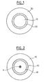
- Such a fiber is in fact made up of a multimode optical core 10 made of silica with a refractive index n 1 and an optical cladding 30 made of a polymer with a refractive index n 2 , with n 1 > n 2 .
- the fiber further comprises an intermediate optical sheath 20 made of heterogeneous polymer, located between said multimode core 10 and said sheath 30, and having a refractive index substantially equal to the refractive index n 1 multimode core.
- the optical signals propagating in the multimode core 10 will penetrate into the intermediate sheath 20 since the refractive index n 1 is the same, the intermediate sheath 20 does not act as a waveguide.
- the thickness of the intermediate optical sheath 20 must be chosen limited by so as to avoid proper propagation of one or more optical modes of the signal.
- the intermediate polymer sheath advantageously has a thickness less than or equal to 10 ⁇ m.
- the intermediate optical sheath 20 is made of heterogeneous polymer, that is to say exhibits inhomogeneities causing changes in optical mode of the signals passing through it.
- the inhomogeneities of the intermediate sheath 20 are inhomogeneities which induce essentially optical effects by local variations in the refractive index n 1 .
- the intermediate sheath 20 can, by example, be composed of an inherently inhomogeneous polymer including local density variations.
- polyurethane acrylate networks present, in their natural structure, hard agglomerates (known under the term of "hard cluster" in English terminology) which induce variations in density and therefore refractive index. These agglomerates are generally distributed so random in the polymer network and must be large enough to cause local light refraction, about 1/20 of the length signal waveform.
- the quantity and size of the agglomerates can be adjusted by a person skilled in the art by varying the resin compositions used to prepare the polymer for this intermediate sheath 20.
- the optical sheath heterogeneous polymer intermediate 20 can be composed of an alloy and / or a mixture of different polymers. Such mixing can be done at a level nanometric or micrometric, depending on the polymers chosen by a person skilled in the art to make this intermediate sheath.
- the optical sheath heterogeneous polymer intermediate 20 can be composed of a polymer containing transparent organic or inorganic particles whose nature, quantity and size can be determined by a person skilled in the art depending on the applications.
- the intermediate optical sheath 20 of heterogeneous polymer can be composed of polymer networks interpenetrated (known by the acronym IPN for Interpenetrating Polymer Network in English terminology) or semi-interpenetrated (SIPN).
- An interpenetrating network corresponds to a macromolecular assembly of at least two networks of partially interlaced polymers
- a semi-interpenetrating network corresponds to a macromolecular assembly of at least one polymer network with at least a linear chain.
- composition of the polymer intermediate sheath heterogeneous are given only by way of illustrative example, and other compositions heterogeneous can be envisaged, such as polymers in solutions, in emulsions, or thermoplastic materials for example.
- the intermediate optical sheath 20 defined in the present invention allows advantageously to improve the coupling of the optical modes propagating in the multimode core 10. Indeed, optical defects, natural or added, in the intermediate sheath 20 of heterogeneous polymer make it possible to cause mode changes in the propagation of optical signals transmitted by the multimode core 10.
- the core of the fiber in which most of the light energy is propagated, is compound of silica which has very good properties in terms of attenuation.
- Such a fiber is particularly suitable for access network applications for broadband transmissions over medium distances.
Landscapes
- Physics & Mathematics (AREA)
- General Physics & Mathematics (AREA)
- Optics & Photonics (AREA)
- Lasers (AREA)
- Glass Compositions (AREA)
- Optical Fibers, Optical Fiber Cores, And Optical Fiber Bundles (AREA)
- Surface Treatment Of Glass Fibres Or Filaments (AREA)
Abstract
Description
- la figure 1 illustre schématiquement par une vue en coupe transversale d'une fibre optique de transmission selon l'invention ;
- la figure 2 illustre schématiquement par une vue en coupe transversale d'une fibre optique amplificatrice selon l'invention.
Claims (9)
- Fibre optique comprenant un coeur optique multimode (10) en silice d'indice de réfraction n1 et au moins une gaine optique (30) en polymère d'indice de réfraction n2, avec n1>n2, caractérisée en ce qu'elle comprend en outre une gaine optique intermédiaire (20) en polymère hétérogène, située entre ledit coeur multimode (10) et ladite gaine optique (30), et ayant un indice de réfraction sensiblement égal à l'indice de réfraction n1 du coeur multimode (10).
- Fibre optique selon la revendication 1, caractérisée en ce que la gaine optique intermédiaire (20) présente une épaisseur inférieure ou égale à 10 µm.
- Fibre optique selon l'une des revendications 1 à 2, caractérisée en ce que la gaine optique intermédiaire (20) en polymère hétérogène est composée d'un polymère intrinsèquement inhomogène incluant des variations de densité locales.
- Fibre optique selon la revendication 3, caractérisée en ce que la gaine optique intermédiaire (20) en polymère hétérogène est composée de réseaux de polyuréthane acrylate.
- Fibre optique selon l'une des revendications 1 à 2, caractérisée en ce que la gaine optique intermédiaire (20) en polymère hétérogène est composée d'un alliage et/ou d'un mélange de polymères différents.
- Fibre optique selon l'une des revendications 1 à 2, caractérisée en ce que la gaine optique intermédiaire (20) en polymère hétérogène est composée de réseaux de polymères interpénétrés ou semi-interpénétrés.
- Fibre optique selon l'une des revendications 1 à 2, caractérisée en ce que la gaine optique intermédiaire (20) en polymère hétérogène est composée d'un polymère contenant des particules transparentes organiques ou inorganiques.
- Fibre optique selon l'une des revendications précédentes, caractérisée ne ce qu'elle comprend un coeur central monomode (9) en silice d'indice de réfraction n0 entouré du coeur multimode (10) en silice d'indice de réfraction n1, avec n0>n1.
- Fibre optique selon la revendication 8, caractérisée en ce qu'elle constitue un amplificateur optique, le coeur central monomode (9) étant dopé avec un matériau amplificateur.
Applications Claiming Priority (2)
| Application Number | Priority Date | Filing Date | Title |
|---|---|---|---|
| FR0112447A FR2830087B1 (fr) | 2001-09-27 | 2001-09-27 | Fibre optique silice a double gaine polymere |
| FR0112447 | 2001-09-27 |
Publications (3)
| Publication Number | Publication Date |
|---|---|
| EP1298464A2 true EP1298464A2 (fr) | 2003-04-02 |
| EP1298464A3 EP1298464A3 (fr) | 2005-01-05 |
| EP1298464B1 EP1298464B1 (fr) | 2007-04-25 |
Family
ID=8867672
Family Applications (1)
| Application Number | Title | Priority Date | Filing Date |
|---|---|---|---|
| EP02292183A Expired - Lifetime EP1298464B1 (fr) | 2001-09-27 | 2002-09-05 | Fibre optique silice à double gaine polymere |
Country Status (5)
| Country | Link |
|---|---|
| US (1) | US6853787B2 (fr) |
| EP (1) | EP1298464B1 (fr) |
| AT (1) | ATE360828T1 (fr) |
| DE (1) | DE60219738T2 (fr) |
| FR (1) | FR2830087B1 (fr) |
Families Citing this family (7)
| Publication number | Priority date | Publication date | Assignee | Title |
|---|---|---|---|---|
| US8731358B2 (en) * | 2008-01-17 | 2014-05-20 | Claude Pare | Multi-cladding fiber |
| KR101134939B1 (ko) | 2009-04-21 | 2012-04-17 | 대한전선 주식회사 | 태양광 전달용 광섬유와 그 제조방법 및 이를 이용한 광케이블 |
| US8596886B2 (en) * | 2011-09-07 | 2013-12-03 | The Boeing Company | Hermetic small form factor optical device packaging for plastic optical fiber networks |
| US10073218B2 (en) * | 2016-03-28 | 2018-09-11 | Massachusetts Institute Of Technology | Metalized double-clad optical fiber |
| US11697833B2 (en) | 2016-11-29 | 2023-07-11 | The Regents Of The University Of California | Antimicrobial susceptibility testing device and method for use with portable electronic device |
| WO2018136474A1 (fr) * | 2017-01-17 | 2018-07-26 | The Regents Of The University Of California | Lecteur de plaque multipuits fluorescente basé sur un téléphone mobile |
| US11009660B2 (en) * | 2017-02-10 | 2021-05-18 | Heptagon Micro Optics Pte. Ltd. | Light guides and manufacture of light guides |
Family Cites Families (13)
| Publication number | Priority date | Publication date | Assignee | Title |
|---|---|---|---|---|
| JPS58142304A (ja) * | 1982-02-17 | 1983-08-24 | Fujitsu Ltd | 光伝送用フアイバ |
| US5696863A (en) * | 1982-08-06 | 1997-12-09 | Kleinerman; Marcos Y. | Distributed fiber optic temperature sensors and systems |
| US4701614A (en) * | 1984-06-25 | 1987-10-20 | Spectran Corporation | Fiber optic pressure sensor |
| US5121460A (en) * | 1991-01-31 | 1992-06-09 | The Charles Stark Draper Lab., Inc. | High-power mode-selective optical fiber laser |
| US5181268A (en) * | 1991-08-12 | 1993-01-19 | Corning Incorporated | Strippable tight buffered optical waveguide fiber |
| DE9202296U1 (de) * | 1992-02-21 | 1993-06-17 | Rofin-Sinar Laser GmbH, 2000 Hamburg | Lichtleitfaser |
| JP3298799B2 (ja) * | 1995-11-22 | 2002-07-08 | ルーセント テクノロジーズ インコーポレイテッド | クラッディングポンプファイバとその製造方法 |
| JPH10160947A (ja) * | 1996-11-29 | 1998-06-19 | Toray Ind Inc | 広帯域プラスチッククラッド光ファイバ |
| JP3479219B2 (ja) * | 1997-06-06 | 2003-12-15 | 三菱電線工業株式会社 | 増幅用光ファイバ |
| US6411762B1 (en) * | 1997-12-09 | 2002-06-25 | Scientific-Atlanta, Inc. | Optical fiber with irregularities at cladding boundary |
| US6304705B1 (en) * | 1999-07-27 | 2001-10-16 | Lucent Technologies Inc. | Mode coupling buffered optical fiber apparatus and method for making |
| US6775443B2 (en) * | 2001-01-29 | 2004-08-10 | Corning Cable Systems Llc | Tight buffered optical cables with release layers |
| US6625363B2 (en) * | 2001-06-06 | 2003-09-23 | Nufern | Cladding-pumped optical fiber |
-
2001
- 2001-09-27 FR FR0112447A patent/FR2830087B1/fr not_active Expired - Fee Related
-
2002
- 2002-09-05 DE DE60219738T patent/DE60219738T2/de not_active Expired - Lifetime
- 2002-09-05 EP EP02292183A patent/EP1298464B1/fr not_active Expired - Lifetime
- 2002-09-05 AT AT02292183T patent/ATE360828T1/de not_active IP Right Cessation
- 2002-09-17 US US10/244,506 patent/US6853787B2/en not_active Expired - Lifetime
Also Published As
| Publication number | Publication date |
|---|---|
| DE60219738D1 (de) | 2007-06-06 |
| DE60219738T2 (de) | 2008-01-17 |
| US20030059187A1 (en) | 2003-03-27 |
| US6853787B2 (en) | 2005-02-08 |
| EP1298464B1 (fr) | 2007-04-25 |
| ATE360828T1 (de) | 2007-05-15 |
| FR2830087A1 (fr) | 2003-03-28 |
| EP1298464A3 (fr) | 2005-01-05 |
| FR2830087B1 (fr) | 2003-12-19 |
Similar Documents
| Publication | Publication Date | Title |
|---|---|---|
| EP1482606B1 (fr) | Fibre optique pour amplification ou pour émission laser | |
| FR2950156A1 (fr) | Fibre optique multimode | |
| EP0511069B1 (fr) | Amplificateur optique dans le domaine spectral 1,26 à 1,34 micron | |
| FR2922657A1 (fr) | Fibre multimode. | |
| EP0368196A2 (fr) | Amplificateur laser à fibre optique dopée | |
| EP1709715B1 (fr) | Fibre optique multimode | |
| FR2514155A1 (fr) | Fibre optique monomode a faible dispersion | |
| EP0561672B1 (fr) | Amplificateur optique intégré et laser mettant en oeuvre un tel amplificateur | |
| EP1298464B1 (fr) | Fibre optique silice à double gaine polymere | |
| FR2706633A1 (fr) | Dispositif optique comportant une fibre optique amorce et procédé pour sa fabrication. | |
| EP0534820B1 (fr) | Source monofréquence de moyenne puissance à fibre optique | |
| EP2685574B1 (fr) | Système d'émission de signal optique | |
| WO2009068800A2 (fr) | Dispositif a fibre optique dopee aux terres rares pour l'emission ou l'amplification d'un signal dans la bande "s" | |
| WO2002003510A1 (fr) | Fibre optique a pompage par la gaine et procede de fabrication d'une telle fibre | |
| WO2008006994A1 (fr) | Dispositif laser à fibre optique de puissance | |
| FR2805899A1 (fr) | Amplification optique a fibre a gaine multimode en bande c | |
| FR2829305A1 (fr) | Fibre optique double coeur avec anneau dope terre rare | |
| WO2009138309A1 (fr) | Dispositif laser monomode de puissance et systeme d'amplication comportant le dispositif laser | |
| FR3068486A1 (fr) | Fibre amplificatrice legerement multimode | |
| EP1696523B1 (fr) | Amplificateur optique à diffusion raman | |
| EP1322978B1 (fr) | Dispositif d'injection pour fibre optique et procede de preparation | |
| WO2000049686A1 (fr) | Amplificateur optique a fibre dopee pour la bande a 1600 nm | |
| EP0984307A1 (fr) | Fibre optique monomode à dispersion décalée et à creux central | |
| Campbell | Review of fiber optical communications | |
| EP1908735A1 (fr) | Fibre optique à gain raman large et plat |
Legal Events
| Date | Code | Title | Description |
|---|---|---|---|
| PUAI | Public reference made under article 153(3) epc to a published international application that has entered the european phase |
Free format text: ORIGINAL CODE: 0009012 |
|
| AK | Designated contracting states |
Kind code of ref document: A2 Designated state(s): AT BE BG CH CY CZ DE DK EE ES FI FR GB GR IE IT LI LU MC NL PT SE SK TR |
|
| AX | Request for extension of the european patent |
Extension state: AL LT LV MK RO SI |
|
| RIN1 | Information on inventor provided before grant (corrected) |
Inventor name: DECAUMONT, ANNE Inventor name: PROVOST, LIONEL Inventor name: ANDRIEU, XAVIER Inventor name: BOUSSELET, PHILIPPE Inventor name: GASCA, LAURENT Inventor name: LEMPEREUR, SIMON |
|
| PUAL | Search report despatched |
Free format text: ORIGINAL CODE: 0009013 |
|
| AK | Designated contracting states |
Kind code of ref document: A3 Designated state(s): AT BE BG CH CY CZ DE DK EE ES FI FR GB GR IE IT LI LU MC NL PT SE SK TR |
|
| AX | Request for extension of the european patent |
Extension state: AL LT LV MK RO SI |
|
| RIC1 | Information provided on ipc code assigned before grant |
Ipc: 7G 02B 6/22 B Ipc: 7H 01S 3/067 B Ipc: 7G 02B 6/16 A |
|
| 17P | Request for examination filed |
Effective date: 20050705 |
|
| AKX | Designation fees paid |
Designated state(s): AT BE BG CH CY CZ DE DK EE ES FI FR GB GR IE IT LI LU MC NL PT SE SK TR |
|
| GRAP | Despatch of communication of intention to grant a patent |
Free format text: ORIGINAL CODE: EPIDOSNIGR1 |
|
| RIC1 | Information provided on ipc code assigned before grant |
Ipc: G02B 6/036 20060101AFI20061031BHEP |
|
| GRAS | Grant fee paid |
Free format text: ORIGINAL CODE: EPIDOSNIGR3 |
|
| GRAA | (expected) grant |
Free format text: ORIGINAL CODE: 0009210 |
|
| RAP1 | Party data changed (applicant data changed or rights of an application transferred) |
Owner name: ALCATEL LUCENT |
|
| AK | Designated contracting states |
Kind code of ref document: B1 Designated state(s): AT BE BG CH CY CZ DE DK EE ES FI FR GB GR IE IT LI LU MC NL PT SE SK TR |
|
| PG25 | Lapsed in a contracting state [announced via postgrant information from national office to epo] |
Ref country code: FI Free format text: LAPSE BECAUSE OF FAILURE TO SUBMIT A TRANSLATION OF THE DESCRIPTION OR TO PAY THE FEE WITHIN THE PRESCRIBED TIME-LIMIT Effective date: 20070425 |
|
| REG | Reference to a national code |
Ref country code: GB Ref legal event code: FG4D Free format text: NOT ENGLISH |
|
| REG | Reference to a national code |
Ref country code: IE Ref legal event code: FG4D Free format text: LANGUAGE OF EP DOCUMENT: FRENCH |
|
| REG | Reference to a national code |
Ref country code: CH Ref legal event code: EP |
|
| REF | Corresponds to: |
Ref document number: 60219738 Country of ref document: DE Date of ref document: 20070606 Kind code of ref document: P |
|
| GBT | Gb: translation of ep patent filed (gb section 77(6)(a)/1977) |
Effective date: 20070608 |
|
| PG25 | Lapsed in a contracting state [announced via postgrant information from national office to epo] |
Ref country code: SE Free format text: LAPSE BECAUSE OF FAILURE TO SUBMIT A TRANSLATION OF THE DESCRIPTION OR TO PAY THE FEE WITHIN THE PRESCRIBED TIME-LIMIT Effective date: 20070725 |
|
| PG25 | Lapsed in a contracting state [announced via postgrant information from national office to epo] |
Ref country code: ES Free format text: LAPSE BECAUSE OF FAILURE TO SUBMIT A TRANSLATION OF THE DESCRIPTION OR TO PAY THE FEE WITHIN THE PRESCRIBED TIME-LIMIT Effective date: 20070805 |
|
| PG25 | Lapsed in a contracting state [announced via postgrant information from national office to epo] |
Ref country code: PT Free format text: LAPSE BECAUSE OF FAILURE TO SUBMIT A TRANSLATION OF THE DESCRIPTION OR TO PAY THE FEE WITHIN THE PRESCRIBED TIME-LIMIT Effective date: 20070925 |
|
| NLV1 | Nl: lapsed or annulled due to failure to fulfill the requirements of art. 29p and 29m of the patents act | ||
| PG25 | Lapsed in a contracting state [announced via postgrant information from national office to epo] |
Ref country code: AT Free format text: LAPSE BECAUSE OF FAILURE TO SUBMIT A TRANSLATION OF THE DESCRIPTION OR TO PAY THE FEE WITHIN THE PRESCRIBED TIME-LIMIT Effective date: 20070425 |
|
| REG | Reference to a national code |
Ref country code: IE Ref legal event code: FD4D |
|
| PG25 | Lapsed in a contracting state [announced via postgrant information from national office to epo] |
Ref country code: BG Free format text: LAPSE BECAUSE OF FAILURE TO SUBMIT A TRANSLATION OF THE DESCRIPTION OR TO PAY THE FEE WITHIN THE PRESCRIBED TIME-LIMIT Effective date: 20070725 Ref country code: CZ Free format text: LAPSE BECAUSE OF FAILURE TO SUBMIT A TRANSLATION OF THE DESCRIPTION OR TO PAY THE FEE WITHIN THE PRESCRIBED TIME-LIMIT Effective date: 20070425 Ref country code: IE Free format text: LAPSE BECAUSE OF FAILURE TO SUBMIT A TRANSLATION OF THE DESCRIPTION OR TO PAY THE FEE WITHIN THE PRESCRIBED TIME-LIMIT Effective date: 20070425 Ref country code: DK Free format text: LAPSE BECAUSE OF FAILURE TO SUBMIT A TRANSLATION OF THE DESCRIPTION OR TO PAY THE FEE WITHIN THE PRESCRIBED TIME-LIMIT Effective date: 20070425 Ref country code: NL Free format text: LAPSE BECAUSE OF FAILURE TO SUBMIT A TRANSLATION OF THE DESCRIPTION OR TO PAY THE FEE WITHIN THE PRESCRIBED TIME-LIMIT Effective date: 20070425 |
|
| PG25 | Lapsed in a contracting state [announced via postgrant information from national office to epo] |
Ref country code: SK Free format text: LAPSE BECAUSE OF FAILURE TO SUBMIT A TRANSLATION OF THE DESCRIPTION OR TO PAY THE FEE WITHIN THE PRESCRIBED TIME-LIMIT Effective date: 20070425 |
|
| PLBE | No opposition filed within time limit |
Free format text: ORIGINAL CODE: 0009261 |
|
| STAA | Information on the status of an ep patent application or granted ep patent |
Free format text: STATUS: NO OPPOSITION FILED WITHIN TIME LIMIT |
|
| BERE | Be: lapsed |
Owner name: ALCATEL LUCENT Effective date: 20070930 |
|
| 26N | No opposition filed |
Effective date: 20080128 |
|
| PG25 | Lapsed in a contracting state [announced via postgrant information from national office to epo] |
Ref country code: MC Free format text: LAPSE BECAUSE OF NON-PAYMENT OF DUE FEES Effective date: 20070930 Ref country code: GR Free format text: LAPSE BECAUSE OF FAILURE TO SUBMIT A TRANSLATION OF THE DESCRIPTION OR TO PAY THE FEE WITHIN THE PRESCRIBED TIME-LIMIT Effective date: 20070726 |
|
| REG | Reference to a national code |
Ref country code: CH Ref legal event code: PL |
|
| PG25 | Lapsed in a contracting state [announced via postgrant information from national office to epo] |
Ref country code: LI Free format text: LAPSE BECAUSE OF NON-PAYMENT OF DUE FEES Effective date: 20070930 Ref country code: CH Free format text: LAPSE BECAUSE OF NON-PAYMENT OF DUE FEES Effective date: 20070930 |
|
| PG25 | Lapsed in a contracting state [announced via postgrant information from national office to epo] |
Ref country code: BE Free format text: LAPSE BECAUSE OF NON-PAYMENT OF DUE FEES Effective date: 20070930 |
|
| PG25 | Lapsed in a contracting state [announced via postgrant information from national office to epo] |
Ref country code: EE Free format text: LAPSE BECAUSE OF FAILURE TO SUBMIT A TRANSLATION OF THE DESCRIPTION OR TO PAY THE FEE WITHIN THE PRESCRIBED TIME-LIMIT Effective date: 20070425 |
|
| PG25 | Lapsed in a contracting state [announced via postgrant information from national office to epo] |
Ref country code: CY Free format text: LAPSE BECAUSE OF FAILURE TO SUBMIT A TRANSLATION OF THE DESCRIPTION OR TO PAY THE FEE WITHIN THE PRESCRIBED TIME-LIMIT Effective date: 20070425 |
|
| PG25 | Lapsed in a contracting state [announced via postgrant information from national office to epo] |
Ref country code: LU Free format text: LAPSE BECAUSE OF NON-PAYMENT OF DUE FEES Effective date: 20070905 |
|
| PG25 | Lapsed in a contracting state [announced via postgrant information from national office to epo] |
Ref country code: TR Free format text: LAPSE BECAUSE OF FAILURE TO SUBMIT A TRANSLATION OF THE DESCRIPTION OR TO PAY THE FEE WITHIN THE PRESCRIBED TIME-LIMIT Effective date: 20070425 |
|
| PG25 | Lapsed in a contracting state [announced via postgrant information from national office to epo] |
Ref country code: IT Free format text: LAPSE BECAUSE OF NON-PAYMENT OF DUE FEES Effective date: 20070930 |
|
| REG | Reference to a national code |
Ref country code: FR Ref legal event code: GC Effective date: 20131018 |
|
| REG | Reference to a national code |
Ref country code: FR Ref legal event code: RG Effective date: 20141016 |
|
| REG | Reference to a national code |
Ref country code: FR Ref legal event code: CA Effective date: 20150521 |
|
| REG | Reference to a national code |
Ref country code: FR Ref legal event code: CA Effective date: 20150521 |
|
| REG | Reference to a national code |
Ref country code: FR Ref legal event code: PLFP Year of fee payment: 14 |
|
| REG | Reference to a national code |
Ref country code: FR Ref legal event code: PLFP Year of fee payment: 15 |
|
| REG | Reference to a national code |
Ref country code: FR Ref legal event code: PLFP Year of fee payment: 16 |
|
| REG | Reference to a national code |
Ref country code: FR Ref legal event code: PLFP Year of fee payment: 17 |
|
| PGFP | Annual fee paid to national office [announced via postgrant information from national office to epo] |
Ref country code: DE Payment date: 20180920 Year of fee payment: 17 Ref country code: FR Payment date: 20180924 Year of fee payment: 17 |
|
| PGFP | Annual fee paid to national office [announced via postgrant information from national office to epo] |
Ref country code: GB Payment date: 20180919 Year of fee payment: 17 |
|
| REG | Reference to a national code |
Ref country code: DE Ref legal event code: R119 Ref document number: 60219738 Country of ref document: DE |
|
| PG25 | Lapsed in a contracting state [announced via postgrant information from national office to epo] |
Ref country code: DE Free format text: LAPSE BECAUSE OF NON-PAYMENT OF DUE FEES Effective date: 20200401 |
|
| GBPC | Gb: european patent ceased through non-payment of renewal fee |
Effective date: 20190905 |
|
| PG25 | Lapsed in a contracting state [announced via postgrant information from national office to epo] |
Ref country code: FR Free format text: LAPSE BECAUSE OF NON-PAYMENT OF DUE FEES Effective date: 20190930 Ref country code: GB Free format text: LAPSE BECAUSE OF NON-PAYMENT OF DUE FEES Effective date: 20190905 |