EP1298450A2 - Ultrasonic receiving apparatus and ultrasonic diagnosing apparatus using the same - Google Patents
Ultrasonic receiving apparatus and ultrasonic diagnosing apparatus using the same Download PDFInfo
- Publication number
- EP1298450A2 EP1298450A2 EP02021187A EP02021187A EP1298450A2 EP 1298450 A2 EP1298450 A2 EP 1298450A2 EP 02021187 A EP02021187 A EP 02021187A EP 02021187 A EP02021187 A EP 02021187A EP 1298450 A2 EP1298450 A2 EP 1298450A2
- Authority
- EP
- European Patent Office
- Prior art keywords
- ultrasonic
- light
- receiving apparatus
- layer film
- detecting element
- Prior art date
- Legal status (The legal status is an assumption and is not a legal conclusion. Google has not performed a legal analysis and makes no representation as to the accuracy of the status listed.)
- Granted
Links
Images


Classifications
-
- A—HUMAN NECESSITIES
- A61—MEDICAL OR VETERINARY SCIENCE; HYGIENE
- A61B—DIAGNOSIS; SURGERY; IDENTIFICATION
- A61B5/00—Measuring for diagnostic purposes; Identification of persons
- A61B5/0093—Detecting, measuring or recording by applying one single type of energy and measuring its conversion into another type of energy
- A61B5/0097—Detecting, measuring or recording by applying one single type of energy and measuring its conversion into another type of energy by applying acoustic waves and detecting light, i.e. acousto-optic measurements
-
- A—HUMAN NECESSITIES
- A61—MEDICAL OR VETERINARY SCIENCE; HYGIENE
- A61B—DIAGNOSIS; SURGERY; IDENTIFICATION
- A61B8/00—Diagnosis using ultrasonic, sonic or infrasonic waves
-
- G—PHYSICS
- G01—MEASURING; TESTING
- G01S—RADIO DIRECTION-FINDING; RADIO NAVIGATION; DETERMINING DISTANCE OR VELOCITY BY USE OF RADIO WAVES; LOCATING OR PRESENCE-DETECTING BY USE OF THE REFLECTION OR RERADIATION OF RADIO WAVES; ANALOGOUS ARRANGEMENTS USING OTHER WAVES
- G01S15/00—Systems using the reflection or reradiation of acoustic waves, e.g. sonar systems
- G01S15/88—Sonar systems specially adapted for specific applications
- G01S15/89—Sonar systems specially adapted for specific applications for mapping or imaging
- G01S15/8906—Short-range imaging systems; Acoustic microscope systems using pulse-echo techniques
- G01S15/8965—Short-range imaging systems; Acoustic microscope systems using pulse-echo techniques using acousto-optical or acousto-electronic conversion techniques
- G01S15/8968—Short-range imaging systems; Acoustic microscope systems using pulse-echo techniques using acousto-optical or acousto-electronic conversion techniques using acoustical modulation of a light beam
-
- G—PHYSICS
- G02—OPTICS
- G02F—OPTICAL DEVICES OR ARRANGEMENTS FOR THE CONTROL OF LIGHT BY MODIFICATION OF THE OPTICAL PROPERTIES OF THE MEDIA OF THE ELEMENTS INVOLVED THEREIN; NON-LINEAR OPTICS; FREQUENCY-CHANGING OF LIGHT; OPTICAL LOGIC ELEMENTS; OPTICAL ANALOGUE/DIGITAL CONVERTERS
- G02F1/00—Devices or arrangements for the control of the intensity, colour, phase, polarisation or direction of light arriving from an independent light source, e.g. switching, gating or modulating; Non-linear optics
- G02F1/01—Devices or arrangements for the control of the intensity, colour, phase, polarisation or direction of light arriving from an independent light source, e.g. switching, gating or modulating; Non-linear optics for the control of the intensity, phase, polarisation or colour
- G02F1/11—Devices or arrangements for the control of the intensity, colour, phase, polarisation or direction of light arriving from an independent light source, e.g. switching, gating or modulating; Non-linear optics for the control of the intensity, phase, polarisation or colour based on acousto-optical elements, e.g. using variable diffraction by sound or like mechanical waves
-
- A—HUMAN NECESSITIES
- A61—MEDICAL OR VETERINARY SCIENCE; HYGIENE
- A61B—DIAGNOSIS; SURGERY; IDENTIFICATION
- A61B5/00—Measuring for diagnostic purposes; Identification of persons
- A61B5/0059—Measuring for diagnostic purposes; Identification of persons using light, e.g. diagnosis by transillumination, diascopy, fluorescence
-
- G—PHYSICS
- G01—MEASURING; TESTING
- G01S—RADIO DIRECTION-FINDING; RADIO NAVIGATION; DETERMINING DISTANCE OR VELOCITY BY USE OF RADIO WAVES; LOCATING OR PRESENCE-DETECTING BY USE OF THE REFLECTION OR RERADIATION OF RADIO WAVES; ANALOGOUS ARRANGEMENTS USING OTHER WAVES
- G01S15/00—Systems using the reflection or reradiation of acoustic waves, e.g. sonar systems
- G01S15/88—Sonar systems specially adapted for specific applications
- G01S15/89—Sonar systems specially adapted for specific applications for mapping or imaging
- G01S15/8906—Short-range imaging systems; Acoustic microscope systems using pulse-echo techniques
- G01S15/8993—Three dimensional imaging systems
-
- G—PHYSICS
- G01—MEASURING; TESTING
- G01S—RADIO DIRECTION-FINDING; RADIO NAVIGATION; DETERMINING DISTANCE OR VELOCITY BY USE OF RADIO WAVES; LOCATING OR PRESENCE-DETECTING BY USE OF THE REFLECTION OR RERADIATION OF RADIO WAVES; ANALOGOUS ARRANGEMENTS USING OTHER WAVES
- G01S7/00—Details of systems according to groups G01S13/00, G01S15/00, G01S17/00
- G01S7/52—Details of systems according to groups G01S13/00, G01S15/00, G01S17/00 of systems according to group G01S15/00
- G01S7/52017—Details of systems according to groups G01S13/00, G01S15/00, G01S17/00 of systems according to group G01S15/00 particularly adapted to short-range imaging
- G01S7/5205—Means for monitoring or calibrating
-
- G—PHYSICS
- G02—OPTICS
- G02F—OPTICAL DEVICES OR ARRANGEMENTS FOR THE CONTROL OF LIGHT BY MODIFICATION OF THE OPTICAL PROPERTIES OF THE MEDIA OF THE ELEMENTS INVOLVED THEREIN; NON-LINEAR OPTICS; FREQUENCY-CHANGING OF LIGHT; OPTICAL LOGIC ELEMENTS; OPTICAL ANALOGUE/DIGITAL CONVERTERS
- G02F2201/00—Constructional arrangements not provided for in groups G02F1/00 - G02F7/00
- G02F2201/34—Constructional arrangements not provided for in groups G02F1/00 - G02F7/00 reflector
- G02F2201/346—Constructional arrangements not provided for in groups G02F1/00 - G02F7/00 reflector distributed (Bragg) reflector
Definitions
- the present invention generally relates to an ultrasonic receiving apparatus for receiving ultrasonic waves. More specifically, the present invention is directed to an ultrasonic diagnosing apparatus to be used in medical diagnoses by receiving ultrasonic waves from biological bodies with employment of such an ultrasonic receiving apparatus.
- one-dimensional sensor array which includes elements (vibrators) for transmitting/receiving ultrasonic waves.
- the vibrators are realized by using piezoelectric ceramics which is typically known as PZT (Pb(lead) zirconate titanate), or by using a polymer piezoelectric element such as PVDF (polyvinyle difluoride).
- PZT Pb(lead) zirconate titanate
- PVDF polyvinyle difluoride
- an optical detecting type sensor is known in this field, by which an optical fiber is utilized and an ultrasonic wave is converted into an optical signal to be detected.
- an optical detecting type ultrasonic sensor the below-mentioned ultrasonic sensors are reported, namely, an optical detecting type sensor using the fiber Bragg grating (will be abbreviated as an "FBG” hereinafter) described in "Underwater Acoustic Sensor with Fiber Bragg Grating" written by TAKAHASHI et al. in National Defense Academy (Japan) , see OPTICAL REVIEW Vol. 4, No. 6 in 1997, p.
- a first object of the present invention is to provide an ultrasonic receiving apparatus capable of detecting an ultrasonic wave in a two-dimensional manner without necessities of electric-wiring works to a large number of very fine elements and without increase of crosstalk and impedance, and furthermore, to manufacture the ultrasonic receiving apparatus in low cost.
- a second object of the present invention is to provide an ultrasonic diagnosing apparatus capable of acquiring either a two-dimensional ultrasonic image or a three-dimensional ultrasonic image by using the above-described ultrasonic receiving apparatus.
- an ultrasonic receiving apparatus comprises: an ultrasonic detecting element having a reception plane capable of receiving ultrasonic waves, for modulating light on the basis of ultrasonic waves applied to respective positions of the reception plane; and a photodetector having a plurality of pixels, for detecting light output from corresponding positions of the ultrasonic detecting element.
- an ultrasonic diagnosing apparatus comprises: a drive signal generating circuit for generating the drive signals; transmission means for transmitting ultrasonic waves in response to drive signals; reception means including an ultrasonic detecting element and a photodetector, the ultrasonic detecting element having a reception plane capable of receiving ultrasonic waves and modulating light on the basis of ultrasonic waves applied to respective positions of the reception plane, the photodetector having a plurality of pixels and detecting light output from corresponding positions of the ultrasonic detecting element to thereby output detection signals; signal processing means for receiving the detection signals output from the reception means to process the received detection signals; control means for controlling both generation timing of the drive signals and acquisition timing of the detection signals; image processing means for constructing image data on the basis of an output signal of the signal processing means; and an image display unit for displaying thereon an image on the basis of the image data.
- the ultrasonic detecting element having the ultrasonic reception plane including positions which correspond to a plurality of pixels of the photodetector is employed, such an ultrasonic receiving apparatus can be manufactured in low cost. That is to say, this ultrasonic receiving apparatus is capable of detecting the ultrasonic waves in a two-dimensional manner without necessities of electric-wiring works to the large number of very fine elements and without increase of crosstalk and impedance. Accordingly, an ultrasonic diagnosing apparatus capable of acquiring a two-dimensional or three-dimensional ultrasonic image with better qualities can be realized by employing such an ultrasonic receiving apparatus.
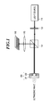
- Fig. 1 is a diagram for schematically showing a basic structure of an ultrasonic receiving apparatus according to one embodiment of the present invention.
- This ultrasonic receiving apparatus includes a light source 11, a beam separator 12, an ultrasonic detecting element 20, a focusing system 15, and a photodetector 16.
- the light source 11 generates single mode laser light having a single wavelength of, for example, 500nm to 1600nm.
- the beam separator 12 is constructed by a half mirror, an optical circulator, a polarization beam splitter, or the like. This beam separator 12 may pass therethrough incident light entered from a first direction toward a second direction, and furthermore, may pass therethrough reflection light returned from the second direction toward a third direction which is different from the first direction. In this embodiment, a half mirror is employed as the beam separator 12.
- This half mirror 12 passes therethrough incident light and reflects thereon the reflection light which returns from a direction opposite to the incident direction so that this reflected light is propagated to a direction at substantially 90 degrees with respect to the incident direction.
- this incident light may be expanded by a beam expander 13.
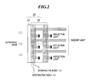
- the ultrasonic detecting element (multi-layer film sensor) 20 includes a base plate 21 and multi-layer film 22 stacked on the base plate 21.
- the ultrasonic detecting element 20 has a wave receiving plane where distortion occurs by receiving propagated ultrasonic waves.
- the ultrasonic detecting element 20 reflects the light which is emitted from the light source 11 and entered into the multi-layer film 22 through the beam separator 12, while modulating the light on the basis of ultrasonic waves applied to the base plate 21.
- the light reflected from the ultrasonic detecting element 20 is reflected by the beam separator 12 and entered into the photodetector 16 having a plurality of pixels.
- the photodetector 16 corresponds to a two-dimensional array detector which is constituted by a CCD, an MOS type sensor, a plurality of PD (photodiodes) or the like.
- the photodetector 16 detects, for a plurality of pixels, the light which is entered from corresponding positions of the ultrasonic detecting element 20 via the beam separator 12.
- This photodetector 16 outputs detection signals in accordance with intensity of light at the respective pixels.
- the reflection light may be directly entered into the photodetector 16, or may be entered via an optical fiber or the like into the photodetector 16.
- the focusing system 15 such as a lens or the like is provided at a rear stage of the beam separator 12, the reflection light may be focused via this focusing system 15 onto the photodetector 16.
- the base plate 21 is a film-shaped base plate where distortion occurs by receiving ultrasonic waves.
- This base plate 21 is shaped of, for example, a circle having a diameter of about 2cm or larger. Two sorts of materials having different refractive indexes are alternately stacked on this base plate 21 so as to form the multi-layer film 22 having a Bragg grating structure.
- Fig. 2 there are shown a material layer "A” having a refractive index "n 1 " and another material layer “B” having a refractive index "n 2 ".
- the Bragg grating selectively reflects thereon such a light having a specific wavelength which satisfies the Bragg's reflection condition, and passes therethrough light having other wavelengths than the above-described specific wavelength.
- this ultrasonic detecting element 20 When the ultrasonic waves are propagated through the ultrasonic detecting element 20, this ultrasonic detecting element 20 is distorted in accordance with the propagation of the ultrasonic waves, and therefore, the pitch "d" of the periodic structure is changed at the respective positions of the multi-layer film 22. As a result, the wavelength " ⁇ " of the light, which is selectively reflected, is changed.
- an inclined band where reflectance is varied is present before or after a center wavelength where the reflectance becomes the highest (namely, the transmittance becomes lowest). While such a detection light having a center wavelength which is located within the range of this inclined band is entered into the multi-layer film 22, the ultrasonic waves are applied to the multi-layer film 22.
- intensity changes of the reflection light in accordance with intensity of the ultrasonic waves at the respective positions of the ultrasonic wave receiving plane can be monitored. Since the intensity changes of the reflection light (or transmission light) are converted into intensity of ultrasonic waves, two-dimensional intensity distribution information of those ultrasonic waves can be acquired.
- quartz glass (SiO 2 ) or optical glass such as BK7 (manufactured by Schott Glass) or the like may be employed.
- a substance used in the material layers "A” and “B” it is preferable to employ a combination of substances having refractive indexes which are different from each other by 10% or more. In other words, in the case of such a refractive index relationship of n 1 ⁇ n 2 , such substances capable of satisfying n 1 x 1.1 ⁇ n 2 are selected. This selection condition is to achieve a high reflectance at a boundary plane between the material layer "A" and the material layer "B".
- both the material layers "A” and “B” are preferably made of such a material which can be easily expanded/compressed. This selection condition is to increase sensitivities when ultrasonic waves are applied to those material layers "A” and "B".
- the combination of such substances capable of satisfying such conditions there are a combination of SiO 2 and a titanium oxide (Ti 2 O 3 ), another combination of SiO 2 and a tantalum oxide (Ta 2 O 5 ) and the like.
- the refractive index of SiO 2 is nearly equal to 1.45 and the refractive index of Ti 2 O 3 is nearly equal to 2.0 with respect to laser light having a wavelength of 1520nm. This fact may sufficiently satisfy the above-described condition. That is, the refractive indexes of those materials are different from each other by 10% or more.
- a layer thickness (film thickness) of the material layer “A” and a layer thickness (film thickness) of the material layer “B” are preferably selected to be substantially 1/4 of the wavelength " ⁇ " of the light which is entered into the multi-layer film 22.
- the pitch of the periodic structure of the multi-layer film 22 becomes substantially 1/2 of the wavelength of the incident light, and the multi-layer film 22 can selectively reflect thereon the light having such a wavelength satisfying the above-described expression (2) of the Bragg's reflection condition and pass therethrough the light having other wavelengths than the above-described wavelength.
- the above-mentioned material layers "A” and “B” are stacked on the substrate 21 in such a manner that multiple layers (for example, 100 layers) of each of those materials are formed thereon by way of a vapor deposition method, a sputtering method, or the like.
- the reflectance becomes higher, and also, the reflectance changes steeply with respective to a change in the wavelengths of incident light, so that the sensitivity of the ultrasonic detecting element 2 can be increased.
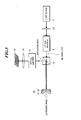
- This modified ultrasonic receiving apparatus is arranged by adding at least one of an optical amplifier 1 and another optical amplifier 2 to the ultrasonic receiving apparatus as shown in Fig. 1.
- the optical amplifier 1 is positioned either between the light source 11 and the beam separator 12 or between the beam expander 13 and the beam separator 12.
- This optical amplifier 1 optically amplifies the light entered from the light source 11, and then emits the amplified light to the beam separator 12.
- the optical amplifier 2 is positioned between the beam separator 12 and the focusing system 15 such as the lens.
- This optical amplifier 2 amplifies the light entered from the beam separator 12, and then emits the amplified light to the focusing system 15.
- the optical amplifier 2 is positioned between the beam separator 12 and the photodetector 16, and amplifies the light entered from the beam separator 12 to emit the amplified light to the photodetector 16.
- optical amplifier for example, such an optical fiber amplifier EDFA (Er-doped optical fiber amplifier) is used into which erbium (Er) has been doped.
- This EDFA can increase intensity of light by about 10 1 to 10 2 times.
- the intensity of light is amplified, the light amount of the reflection light which is entered into the photodetector 16 is increased. As a result, an adverse influence of electric noise occurred in the photodetector 16 can be reduced, and the S/N (signal-to-noise) ratio of the ultrasonic receiving apparatus can be improved.
- the S/N ratio of this ultrasonic receiving apparatus can be furthermore improved.
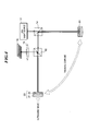
- An ultrasonic receiving apparatus as shown in Fig. 4 is realized by replacing the light source 11 of the ultrasonic receiving apparatus as shown in Fig. 1 by another light source, namely a broadband light source.
- a spectrum of the light which is generated from the broadband light source is narrowed by a narrow-band filter, and then, the narrow-band light is employed.
- an ASE (amplified spontaneous emission) light source for emitting amplified spontaneous emission light for example, an ASE (amplified spontaneous emission) light source for emitting amplified spontaneous emission light, and a broadband optical fiber light source may be employed.
- an ASE light source 17 is used as the broadband light source.
- This ASE light source 17 is realized by changing a structure of a broadband optical fiber amplifier so as to emit the amplified spontaneous emission light.
- the detailed structure or operation of the broadband optical fiber amplifier is described in, for example, "BROADBAND OPTICAL FIBER AMPLIFIER" written by H.OKOSHI et al. (see Japanese Electronic Information Communication Institute Publication Vol. 82, No. 7, 1999, pp. 718-724).
- Fig. 5 illustratively shows a basic idea of the ASE light source 17 as shown in Fig. 4.
- This ASE light source 17 includes an optical fiber 4 for amplifying light.
- a lens 5 is mounted on one edge portion of this optical fiber 4, and a Bragg grating portion 6 capable of reflecting excitation light is formed on the other edge portion thereof.
- a laser oscillator 7 is arranged as an excitation light source on a left side of the lens 5, in this drawing. Laser light which is generated from the laser oscillator 7 is entered via the lens 5 into the optical fiber 4, and then, this entered laser light is amplified by this optical fiber 4. A portion of this amplified laser light may pass through the Bragg grating portion 6 as spontaneous emission light.
- the light generated from the ASE light source 17 is entered into the beam separator 14.
- This beam separator 14 passes the light entered from a first direction to a second direction, and also, passes the reflection light returned from the second direction to a third direction which is different from the first direction.
- a half mirror is employed as the beam separator 14.
- an optical circulator or a polarization beam splitter may be employed.
- a narrow-band filter 23 is provided which is made of the same material as that of the ultrasonic detecting element 20.
- the light which is entered into this narrow-band filter 23 is reflected by a multi-layer film having a Bragg grating structure included in the narrow-band filter 23, and then, this reflected light is again entered into the beam separator 14.
- the spontaneous emission light generated from the ASE light source 17 passes through the narrow-band filter 23, so that a spectrum of this spontaneous emission light can be narrowed.
- the light reflected by the narrow-band filter 23 is again entered into the beam separator 14, and the propagation path of this light is changed, and then, the resultant light is entered into the beam separator 12.
- the light which has passed through the beam separator 12 is entered into the ultrasonic detecting element 20 so as to be modulated.
- a center wavelength of reflection light is changed due to a temperature variation in a ratio of 0.01nm/°C.
- a light source for generating laser light having a single wavelength there is such a problem that the sensitivity of the ultrasonic detecting element 20 which is constituted by the Bragg grating portion is largely changed in accordance with a temperature variation.
- both the narrow-band filter 23 and the ultrasonic detecting element 20 are made by employing the same material, and thermal coupling therebetween is established by, for example, coupling the narrow-band filter 23 to the ultrasonic detecting element 20 by employing such a material having a high thermal conductivity or physically locating the narrow-band filter 23 in proximity to the ultrasonic detecting element 20.
- a heat pipe may be arranged around the narrow-band filter 23 and the ultrasonic detecting element 20.
- the temperature at the Bragg grating portion of the narrow-band filter 23 can be made substantially equal to the temperature at the Bragg grating portion of the ultrasonic detecting element 20, even when the reflection characteristic of the ultrasonic detecting element 20 is shifted by the temperature, the wavelength of the light which is entered into the ultrasonic detecting element 20 is similarly shifted, so that the change in the sensitivities of the ultrasonic receiving apparatus can be reduced.
- FIG. 6 is a schematic block diagram for showing an arrangement of an ultrasonic diagnosing apparatus according to this embodiment.
- This ultrasonic diagnosing apparatus is constituted by applying thereto the above-described ultrasonic receiving apparatus. That is, the ultrasonic detecting element 20 as shown in Fig. 2 is employed in an ultrasonic detecting unit 50 of this ultrasonic diagnosing apparatus. As shown in Fig. 6, this ultrasonic diagnosing apparatus includes an ultrasonic transmitting unit 40 and a drive signal generating circuit 30. The ultrasonic transmitting unit 40 transmits ultrasonic waves in accordance with drive signals generated from the drive signal generating circuit 30.
- the ultrasonic transmitting unit 40 includes a material (piezoelectric element) having a piezoelectric characteristic.
- This piezoelectric element is realized by piezoelectric ceramics which is typically known as PZT (Pb (lead) zirconate titanate) , or a polymer piezoelectric element such as PVDF (polyvinyl difluoride) .
- PZT Pb (lead) zirconate titanate
- PVDF polyvinyl difluoride
- the ultrasonic waves transmitted from the ultrasonic transmitting unit 40 are reflected from a diagnostic object, and then, the reflected ultrasonic waves (namely, ultrasonic echoes) are received by the ultrasonic detecting unit 50.
- the light which has been generated from the light source and has passed through the beam separator 12 is entered into the ultrasonic detecting unit 50, this light is modulated on the basis of the ultrasonic beams applied to the ultrasonic detecting unit 50, and then, this modulated light is reflected from this ultrasonic detecting unit 50.
- the reflected light is entered via the beam separator 12 and the focusing system 15 into the photodetector 16 so as to be detected in a two-dimensional manner.
- This ultrasonic diagnosing apparatus further includes a signal processing means 60 including both a signal processing unit 61 and an A/D converter 62, a timing control unit 70, a primary storage unit 80, an image processing unit 90, an image display unit 100, and a secondary storage unit 110.
- a signal processing means 60 including both a signal processing unit 61 and an A/D converter 62, a timing control unit 70, a primary storage unit 80, an image processing unit 90, an image display unit 100, and a secondary storage unit 110.
- a detection signal output from the photodetector 16 is entered into a signal processing unit 61, and the detection signal processed by the signal processing unit 61 is converted into a digital signal in the A/D converter 62.
- the primary storage unit 80 stores thereinto plural sheets of plane data acquired by the signal processing means 60.
- the image processing unit 90 reconstructs either two-dimensional data or three-dimensional data on the basis of these plane data, and also, executes such process operations as an interpolation process, a response modulation process, and a gradation process.
- the image display unit 100 corresponds to a display apparatus such as a CRT or an LCD, for example, and displays thereon an image on the basis of the image data to which these process operations have been carried out.
- the secondary storage unit 110 stores thereinto data which has been processed by the image processing unit 90.
- the timing control unit 70 controls the drive signal generating unit 30 to generate the drive signal at predetermined timing, and also controls the signal processing unit 61 to acquire detection signals from the photodetector 16 after a predetermined time period has passed from a transmission time instant.
- the timing control unit 70 controls both timing of the drive signal and timing of the detection signal so as to limit a readout time range, so that reflections of ultrasonic waves from a specific depth of an object to be inspected can be optically detected.
- both the ultrasonic detecting unit 50 and the ultrasonic transmitting unit 40 are formed in an integral manner, so that an ultrasonic probe 120 is formed.
- the below-mentioned three sorts of transmission methods of ultrasonic waves may be conceived in the drive signal generating circuit 30 and the ultrasonic transmitting unit 40.
- data acquisition time instants and contents of data in the signal processing unit 61 are changed.
- an ultrasonic detecting element having an ultrasonic receiving plane corresponding to a plurality of pixels of a photodetector since an ultrasonic detecting element having an ultrasonic receiving plane corresponding to a plurality of pixels of a photodetector is employed, ultrasonic waves can be detected in a two-dimensional manner.
- Such an ultrasonic detecting element can be manufactured in low cost, as compared with a case where a plurality of fiber Bragg gratings are formed into an array. As a result, the manufacturing cost of the ultrasonic receiving apparatus can be lowered.
- layers of a multi-layer film as the ultrasonic detecting element are formed one by one in the vapor deposition method, the sputtering method or the like, a plurality of materials having largely different refractive indexes can be selected.
Landscapes
- Physics & Mathematics (AREA)
- Life Sciences & Earth Sciences (AREA)
- Health & Medical Sciences (AREA)
- Engineering & Computer Science (AREA)
- Acoustics & Sound (AREA)
- Remote Sensing (AREA)
- Radar, Positioning & Navigation (AREA)
- Heart & Thoracic Surgery (AREA)
- Animal Behavior & Ethology (AREA)
- Veterinary Medicine (AREA)
- Public Health (AREA)
- Biophysics (AREA)
- Pathology (AREA)
- Biomedical Technology (AREA)
- General Health & Medical Sciences (AREA)
- Medical Informatics (AREA)
- Molecular Biology (AREA)
- Surgery (AREA)
- Nonlinear Science (AREA)
- General Physics & Mathematics (AREA)
- Nuclear Medicine, Radiotherapy & Molecular Imaging (AREA)
- Radiology & Medical Imaging (AREA)
- Computer Networks & Wireless Communication (AREA)
- Optics & Photonics (AREA)
- Ultra Sonic Daignosis Equipment (AREA)
- Investigating Or Analyzing Materials By The Use Of Ultrasonic Waves (AREA)
- Optical Modulation, Optical Deflection, Nonlinear Optics, Optical Demodulation, Optical Logic Elements (AREA)
- Transducers For Ultrasonic Waves (AREA)
Abstract
Description
Claims (24)
- An ultrasonic receiving apparatus comprising:an ultrasonic detecting element (20) having a reception plane capable of receiving ultrasonic waves, for modulating light on the basis of ultrasonic waves applied to respective positions of said reception plane; anda photodetector (16) having a plurality of pixels, for detecting light output from corresponding positions of said ultrasonic detecting element.
- An ultrasonic receiving apparatus according to claim 1, wherein:said ultrasonic detecting element (20) includes a multi-layer film (22) formed by alternately stacking two sorts of materials having different refractive indexes from each other.
- An ultrasonic receiving apparatus according to claim 2, wherein:said two sorts of materials have refractive indexes which are different from each other by at least 10%.
- An ultrasonic receiving apparatus according to claim 2, wherein:layers of said two sorts of materials which constitute said multi-layer film (22) include a layer having a film thickness of substantially 1/4 of a wavelength of light entered into said multi-layer film.
- An ultrasonic receiving apparatus according to claim 3, wherein:layers of said two sorts of materials which constitute said multi-layer film (22) include a layer having a film thickness of substantially 1/4 of a wavelength of light entered into said multi-layer film.
- An ultrasonic receiving apparatus according to claim 4, wherein:layers of said two sorts of materials which constitute said multi-layer film (22) further include a layer having a film thickness of substantially 1/2 of a wavelength of light entered into said multi-layer film.
- An ultrasonic receiving apparatus according to claim 5, wherein:layers of said two sorts of materials which constitute said multi-layer film (22) further include a layer having a film thickness of substantially 1/2 of a wavelength of light entered into said multi-layer film.
- An ultrasonic receiving apparatus according to claim 1, wherein:said photodetector (16) includes any one of a CCD (charge-coupled device), an MOS (metal oxide semiconductor) type sensor, and a plurality of photodiodes.
- An ultrasonic receiving apparatus according to claim 1, further comprising:a beam expander (13) for expanding light generated from a light source (11).
- An ultrasonic receiving apparatus according to claim 1, further comprising:an optical amplifier (1) for amplifying light generated from a light source (11) to enter the amplified light into said ultrasonic detecting element (20).
- An ultrasonic receiving apparatus according to claim 1, further comprising:an optical amplifier (2) for amplifying light output from said ultrasonic detecting element (20) to enter the amplified light into said photodetector (16).
- An ultrasonic receiving apparatus according to claim 1, further comprising:a light source (11) for generating single-mode laser light having a wavelength of 500nm to 1,600nm.
- An ultrasonic receiving apparatus according to claim 1, further comprising:a broadband light source; anda narrow-band filter (23) for narrowing a spectrum of light generated from said broadband light source.
- An ultrasonic receiving apparatus according to claim 13, wherein:said broadband light source includes an ASE (amplified spontaneous emission) light source (17) for emitting amplified spontaneous emission light.
- An ultrasonic receiving apparatus according to claim 13, wherein:said narrow-band filter (23) has a Bragg grating structure constituted by using the same material as that of a Bragg grating structure of said ultrasonic detecting element (20); andthe Bragg grating structure of said narrow-band filter (23) is thermally coupled to the Bragg grating structure of said ultrasonic detecting element (20).
- An ultrasonic diagnosing apparatus comprising:a drive signal generating circuit (30) for generating drive signals;transmission means (40) for transmitting ultrasonic waves in response to the drive signals;reception means including an ultrasonic detecting element (20) and a photodetector (16), said ultrasonic detecting element (20) having a reception plane capable of receiving ultrasonic waves and modulating light on the basis of ultrasonic waves applied to respective positions of said reception plane, said photodetector (16) having a plurality of pixels and detecting light output from corresponding positions of said ultrasonic detecting element to thereby output detection signals;signal processing means (60) for receiving the detection signals output from said reception means to process the received detection signals;control means (70) for controlling both generation timing of the drive signals and acquisition timing of the detection signals;image processing means (90) for constructing image data on the basis of an output signal of said signal processing means (60) ; andan image display unit (100) for displaying thereon an image on the basis of the image data.
- An ultrasonic diagnosing apparatus according to claim 16, wherein:said transmission means (40) belongs to a piezoelectric type ultrasonic transmission means for generating ultrasonic waves in response to voltage applied thereto.
- An ultrasonic diagnosing apparatus according to claim 16, wherein:said ultrasonic detecting element (20) includes a multi-layer film (22) formed by alternately stacking two sorts of materials having different refractive indexes from each other.
- An ultrasonic diagnosing apparatus according to claim 18, wherein:said two sorts of materials have refractive indexes which are different from each other by not less than 10%.
- An ultrasonic diagnosing apparatus according to claim 18, wherein:layers of said two sorts of materials which constitute said multi-layer film (22) include a layer having a film thickness of substantially 1/4 of a wavelength of light entered into said multi-layer film.
- An ultrasonic diagnosing apparatus according to claim 19, wherein:layers of said two sorts of materials which constitute said multi-layer film (22) include a layer having a film thickness of substantially 1/4 of a wavelength of light entered into said multi-layer film.
- An ultrasonic diagnosing apparatus according to claim 20, wherein:layers of said two sorts of materials which constitute said multi-layer film (22) further include a layer having a film thickness of substantially 1/2 of a wavelength of light entered into said multi-layer film.
- An ultrasonic diagnosing apparatus according to claim 21, wherein:layers of said two sorts of materials which constitute said multi-layer film (22) further include a layer having a film thickness of substantially 1/2 of a wavelength of light entered into said multi-layer film.
- An ultrasonic diagnosing apparatus according to claim 16, wherein:both said transmission means (40) and said ultrasonic detecting element (20) included in said detection means are formed in an integral shape to thereby constitute an ultrasonic wave probe (120).
Applications Claiming Priority (2)
| Application Number | Priority Date | Filing Date | Title |
|---|---|---|---|
| JP2001296317 | 2001-09-27 | ||
| JP2001296317A JP4266548B2 (en) | 2001-09-27 | 2001-09-27 | Ultrasonic receiver and ultrasonic diagnostic apparatus using the same |
Publications (3)
| Publication Number | Publication Date |
|---|---|
| EP1298450A2 true EP1298450A2 (en) | 2003-04-02 |
| EP1298450A3 EP1298450A3 (en) | 2004-11-10 |
| EP1298450B1 EP1298450B1 (en) | 2006-11-15 |
Family
ID=19117586
Family Applications (1)
| Application Number | Title | Priority Date | Filing Date |
|---|---|---|---|
| EP02021187A Expired - Lifetime EP1298450B1 (en) | 2001-09-27 | 2002-09-24 | Optical Ultrasonic receiving apparatus and ultrasonic diagnosing apparatus using the same |
Country Status (5)
| Country | Link |
|---|---|
| US (1) | US6740035B2 (en) |
| EP (1) | EP1298450B1 (en) |
| JP (1) | JP4266548B2 (en) |
| KR (1) | KR20030027833A (en) |
| DE (1) | DE60216030T2 (en) |
Families Citing this family (11)
| Publication number | Priority date | Publication date | Assignee | Title |
|---|---|---|---|---|
| AU5948499A (en) | 1998-03-05 | 1999-11-29 | Victor Spivak | Optical-acoustic imaging device |
| US7245789B2 (en) | 2002-10-07 | 2007-07-17 | Vascular Imaging Corporation | Systems and methods for minimally-invasive optical-acoustic imaging |
| JP4377666B2 (en) * | 2003-12-04 | 2009-12-02 | ニスカ株式会社 | Sheet feeding apparatus and image reading apparatus |
| CN100556059C (en) * | 2003-12-04 | 2009-10-28 | 尼司卡股份有限公司 | Thin slice resending detecting method and thin slice feeder and adopt its image read-out |
| WO2006070669A1 (en) * | 2004-12-27 | 2006-07-06 | Olympus Corporation | Medical image processing apparatus, and medical image processing method |
| US7599588B2 (en) | 2005-11-22 | 2009-10-06 | Vascular Imaging Corporation | Optical imaging probe connector |
| JP4713382B2 (en) * | 2006-03-28 | 2011-06-29 | 富士フイルム株式会社 | Ultrasonic diagnostic apparatus and data analysis measurement apparatus |
| WO2010039950A1 (en) * | 2008-10-02 | 2010-04-08 | Eberle Michael J | Optical ultrasound receiver |
| JP5765332B2 (en) * | 2010-03-16 | 2015-08-19 | コニカミノルタ株式会社 | Ultrasonic diagnostic equipment |
| WO2013056071A1 (en) | 2011-10-14 | 2013-04-18 | Beam Technologies, Llc | Oral health care implement and system with oximetry sensor |
| CN111728604A (en) * | 2020-06-06 | 2020-10-02 | 东南大学 | An implantable gastric slow wave detection device based on ultrasonic fiber grating coupled array |
Family Cites Families (4)
| Publication number | Priority date | Publication date | Assignee | Title |
|---|---|---|---|---|
| IL116789A (en) * | 1995-01-24 | 1999-04-11 | Massachusetts Inst Technology | Device and method for time-resolved optical measurements |
| US5566133A (en) * | 1995-11-29 | 1996-10-15 | General Electric Company | System and method of binary optical communication for ultrasonic probe |
| US5748318A (en) * | 1996-01-23 | 1998-05-05 | Brown University Research Foundation | Optical stress generator and detector |
| GB9921970D0 (en) * | 1999-09-16 | 1999-11-17 | Univ London | An optical interferometer sensor array |
-
2001
- 2001-09-27 JP JP2001296317A patent/JP4266548B2/en not_active Expired - Fee Related
-
2002
- 2002-09-17 US US10/244,442 patent/US6740035B2/en not_active Expired - Fee Related
- 2002-09-24 DE DE60216030T patent/DE60216030T2/en not_active Expired - Lifetime
- 2002-09-24 EP EP02021187A patent/EP1298450B1/en not_active Expired - Lifetime
- 2002-09-27 KR KR1020020058969A patent/KR20030027833A/en not_active Ceased
Also Published As
| Publication number | Publication date |
|---|---|
| KR20030027833A (en) | 2003-04-07 |
| JP2003093383A (en) | 2003-04-02 |
| DE60216030T2 (en) | 2007-06-28 |
| US6740035B2 (en) | 2004-05-25 |
| DE60216030D1 (en) | 2006-12-28 |
| JP4266548B2 (en) | 2009-05-20 |
| EP1298450B1 (en) | 2006-11-15 |
| US20030060707A1 (en) | 2003-03-27 |
| EP1298450A3 (en) | 2004-11-10 |
Similar Documents
| Publication | Publication Date | Title |
|---|---|---|
| US6699192B2 (en) | Ultrasonic receiving apparatus and ultrasonic imaging apparatus | |
| EP1154269B1 (en) | Ultrasonic receiver and ultrasonic diagnostic apparatus | |
| US6984819B2 (en) | Optical converting type ultrasonic receiving apparatus | |
| US6740035B2 (en) | Ultrasonic receiving apparatus and ultrasonic diagnosing apparatus using the same | |
| EP1348979A1 (en) | Ultrasonic receiving apparatus and ultrasonic receiving method | |
| US6494836B2 (en) | Method of generating image data and ultrasonic diagnostic apparatus using the same | |
| US6783494B2 (en) | Ultrasonic probe and ultrasonic diagnosing apparatus using the same | |
| US6881189B2 (en) | Ultrasonic receiving apparatus and ultrasonic receiving method | |
| JP3883481B2 (en) | Ultrasonic receiver | |
| JP2003169802A (en) | Ultrasonic probe and ultrasonic diagnosis apparatus using the same | |
| JP2002301076A (en) | Ultrasonic probe, ultrasonic receiving device, and ultrasonic diagnostic apparatus | |
| JP4076872B2 (en) | Ultrasonic receiver | |
| JP4076873B2 (en) | Ultrasonic receiving apparatus and ultrasonic receiving method | |
| JP3995612B2 (en) | Ultrasonic receiving apparatus and ultrasonic receiving method | |
| JP2002272737A (en) | Ultrasonic receiver and ultrasonic diagnostic equipment using the same | |
| JP2003102734A (en) | Ultrasonic reception method, ultrasonic reception device, and ultrasonic diagnostic equipment | |
| JP2003265473A (en) | Ultrasonic imaging apparatus |
Legal Events
| Date | Code | Title | Description |
|---|---|---|---|
| PUAI | Public reference made under article 153(3) epc to a published international application that has entered the european phase |
Free format text: ORIGINAL CODE: 0009012 |
|
| AK | Designated contracting states |
Kind code of ref document: A2 Designated state(s): AT BE BG CH CY CZ DE DK EE ES FI FR GB GR IE IT LI LU MC NL PT SE SK TR |
|
| AX | Request for extension of the european patent |
Extension state: AL LT LV MK RO SI |
|
| PUAL | Search report despatched |
Free format text: ORIGINAL CODE: 0009013 |
|
| RIC1 | Information provided on ipc code assigned before grant |
Ipc: 7G 01S 15/89 B Ipc: 7A 61B 8/00 B Ipc: 7G 01S 7/52 A |
|
| AK | Designated contracting states |
Kind code of ref document: A3 Designated state(s): AT BE BG CH CY CZ DE DK EE ES FI FR GB GR IE IT LI LU MC NL PT SE SK TR |
|
| AX | Request for extension of the european patent |
Extension state: AL LT LV MK RO SI |
|
| 17P | Request for examination filed |
Effective date: 20050207 |
|
| AKX | Designation fees paid |
Designated state(s): DE FR GB |
|
| 17Q | First examination report despatched |
Effective date: 20050620 |
|
| GRAP | Despatch of communication of intention to grant a patent |
Free format text: ORIGINAL CODE: EPIDOSNIGR1 |
|
| RTI1 | Title (correction) |
Free format text: OPTICAL ULTRASONIC RECEIVING APPARATUS AND ULTRASONIC DIAGNOSING APPARATUS USING THE SAME |
|
| GRAS | Grant fee paid |
Free format text: ORIGINAL CODE: EPIDOSNIGR3 |
|
| GRAA | (expected) grant |
Free format text: ORIGINAL CODE: 0009210 |
|
| AK | Designated contracting states |
Kind code of ref document: B1 Designated state(s): DE FR GB |
|
| REG | Reference to a national code |
Ref country code: GB Ref legal event code: FG4D |
|
| REF | Corresponds to: |
Ref document number: 60216030 Country of ref document: DE Date of ref document: 20061228 Kind code of ref document: P |
|
| RAP2 | Party data changed (patent owner data changed or rights of a patent transferred) |
Owner name: FUJIFILM CORPORATION |
|
| REG | Reference to a national code |
Ref country code: GB Ref legal event code: 732E |
|
| ET | Fr: translation filed | ||
| PLBE | No opposition filed within time limit |
Free format text: ORIGINAL CODE: 0009261 |
|
| STAA | Information on the status of an ep patent application or granted ep patent |
Free format text: STATUS: NO OPPOSITION FILED WITHIN TIME LIMIT |
|
| REG | Reference to a national code |
Ref country code: FR Ref legal event code: CD Ref country code: FR Ref legal event code: TP |
|
| 26N | No opposition filed |
Effective date: 20070817 |
|
| PGFP | Annual fee paid to national office [announced via postgrant information from national office to epo] |
Ref country code: GB Payment date: 20110921 Year of fee payment: 10 Ref country code: DE Payment date: 20110831 Year of fee payment: 10 Ref country code: FR Payment date: 20110922 Year of fee payment: 10 |
|
| GBPC | Gb: european patent ceased through non-payment of renewal fee |
Effective date: 20120924 |
|
| REG | Reference to a national code |
Ref country code: FR Ref legal event code: ST Effective date: 20130531 |
|
| PG25 | Lapsed in a contracting state [announced via postgrant information from national office to epo] |
Ref country code: GB Free format text: LAPSE BECAUSE OF NON-PAYMENT OF DUE FEES Effective date: 20120924 Ref country code: DE Free format text: LAPSE BECAUSE OF NON-PAYMENT OF DUE FEES Effective date: 20130403 |
|
| PG25 | Lapsed in a contracting state [announced via postgrant information from national office to epo] |
Ref country code: FR Free format text: LAPSE BECAUSE OF NON-PAYMENT OF DUE FEES Effective date: 20121001 |
|
| REG | Reference to a national code |
Ref country code: DE Ref legal event code: R119 Ref document number: 60216030 Country of ref document: DE Effective date: 20130403 |