EP1298431A2 - High-precision method and apparatus for evaluating creep damage - Google Patents
High-precision method and apparatus for evaluating creep damage Download PDFInfo
- Publication number
- EP1298431A2 EP1298431A2 EP02021873A EP02021873A EP1298431A2 EP 1298431 A2 EP1298431 A2 EP 1298431A2 EP 02021873 A EP02021873 A EP 02021873A EP 02021873 A EP02021873 A EP 02021873A EP 1298431 A2 EP1298431 A2 EP 1298431A2
- Authority
- EP
- European Patent Office
- Prior art keywords
- creep damage
- working
- evaluated
- heat resistant
- resistant steel
- Prior art date
- Legal status (The legal status is an assumption and is not a legal conclusion. Google has not performed a legal analysis and makes no representation as to the accuracy of the status listed.)
- Ceased
Links
- 238000000034 method Methods 0.000 title claims description 25
- 239000013078 crystal Substances 0.000 claims description 67
- 238000003466 welding Methods 0.000 claims description 47
- 229910000831 Steel Inorganic materials 0.000 claims description 32
- 239000010959 steel Substances 0.000 claims description 32
- 239000010953 base metal Substances 0.000 claims description 24
- 239000002245 particle Substances 0.000 claims description 9
- 229910000734 martensite Inorganic materials 0.000 claims description 8
- NBIIXXVUZAFLBC-UHFFFAOYSA-N Phosphoric acid Chemical compound OP(O)(O)=O NBIIXXVUZAFLBC-UHFFFAOYSA-N 0.000 claims description 6
- 229910001563 bainite Inorganic materials 0.000 claims description 6
- 229910001562 pearlite Inorganic materials 0.000 claims description 6
- 229910000859 α-Fe Inorganic materials 0.000 claims description 6
- 229910000963 austenitic stainless steel Inorganic materials 0.000 claims description 5
- 238000010894 electron beam technology Methods 0.000 claims description 4
- 229910000147 aluminium phosphate Inorganic materials 0.000 claims description 3
- 230000001678 irradiating effect Effects 0.000 claims 1
- 230000035882 stress Effects 0.000 description 18
- 238000012360 testing method Methods 0.000 description 14
- 239000000463 material Substances 0.000 description 10
- 229910001566 austenite Inorganic materials 0.000 description 9
- 238000011156 evaluation Methods 0.000 description 9
- 238000010586 diagram Methods 0.000 description 5
- 230000001066 destructive effect Effects 0.000 description 4
- 230000000694 effects Effects 0.000 description 3
- 238000010438 heat treatment Methods 0.000 description 3
- 229910001220 stainless steel Inorganic materials 0.000 description 3
- 239000010935 stainless steel Substances 0.000 description 3
- LFQSCWFLJHTTHZ-UHFFFAOYSA-N Ethanol Chemical compound CCO LFQSCWFLJHTTHZ-UHFFFAOYSA-N 0.000 description 2
- 238000005520 cutting process Methods 0.000 description 2
- 230000007423 decrease Effects 0.000 description 2
- 230000003247 decreasing effect Effects 0.000 description 2
- 238000007542 hardness measurement Methods 0.000 description 2
- 238000005259 measurement Methods 0.000 description 2
- VLTRZXGMWDSKGL-UHFFFAOYSA-N perchloric acid Chemical compound OCl(=O)(=O)=O VLTRZXGMWDSKGL-UHFFFAOYSA-N 0.000 description 2
- 238000002360 preparation method Methods 0.000 description 2
- 230000032683 aging Effects 0.000 description 1
- 238000004458 analytical method Methods 0.000 description 1
- 230000005465 channeling Effects 0.000 description 1
- 238000010276 construction Methods 0.000 description 1
- 229910003460 diamond Inorganic materials 0.000 description 1
- 239000010432 diamond Substances 0.000 description 1
- 238000001887 electron backscatter diffraction Methods 0.000 description 1
- 229910001651 emery Inorganic materials 0.000 description 1
- 238000012423 maintenance Methods 0.000 description 1
- 239000011347 resin Substances 0.000 description 1
- 229920005989 resin Polymers 0.000 description 1
- 239000000523 sample Substances 0.000 description 1
Images



Classifications
-
- G—PHYSICS
- G01—MEASURING; TESTING
- G01N—INVESTIGATING OR ANALYSING MATERIALS BY DETERMINING THEIR CHEMICAL OR PHYSICAL PROPERTIES
- G01N23/00—Investigating or analysing materials by the use of wave or particle radiation, e.g. X-rays or neutrons, not covered by groups G01N3/00 – G01N17/00, G01N21/00 or G01N22/00
- G01N23/22—Investigating or analysing materials by the use of wave or particle radiation, e.g. X-rays or neutrons, not covered by groups G01N3/00 – G01N17/00, G01N21/00 or G01N22/00 by measuring secondary emission from the material
- G01N23/225—Investigating or analysing materials by the use of wave or particle radiation, e.g. X-rays or neutrons, not covered by groups G01N3/00 – G01N17/00, G01N21/00 or G01N22/00 by measuring secondary emission from the material using electron or ion
- G01N23/2251—Investigating or analysing materials by the use of wave or particle radiation, e.g. X-rays or neutrons, not covered by groups G01N3/00 – G01N17/00, G01N21/00 or G01N22/00 by measuring secondary emission from the material using electron or ion using incident electron beams, e.g. scanning electron microscopy [SEM]
-
- G—PHYSICS
- G01—MEASURING; TESTING
- G01N—INVESTIGATING OR ANALYSING MATERIALS BY DETERMINING THEIR CHEMICAL OR PHYSICAL PROPERTIES
- G01N15/00—Investigating characteristics of particles; Investigating permeability, pore-volume or surface-area of porous materials
- G01N15/10—Investigating individual particles
-
- G—PHYSICS
- G01—MEASURING; TESTING
- G01N—INVESTIGATING OR ANALYSING MATERIALS BY DETERMINING THEIR CHEMICAL OR PHYSICAL PROPERTIES
- G01N17/00—Investigating resistance of materials to the weather, to corrosion, or to light
- G01N17/006—Investigating resistance of materials to the weather, to corrosion, or to light of metals
Definitions
- the present invention relates to a method and an apparatus for evaluating an extent of the creep damage of high-tension heat resistant steel used for such as a power plant with precision and for short time.
- High-tension ferritic steel or austenite stainless steel is used in recent high-pressure steam power plants.
- the metallographical method has not been applied to these steels because a structural change owning to the creep damage is little.
- evaluation methods for creep damage such as a method by convenient hardness measurement have been proposed.
- the applicant of the present invention disclosed a method for evaluating the rest of the life of ferritic heat resistant steel in Japanese laid open patent publication P1990-248860A.
- the method comprises the steps of measuring a hardness of both the part influenced by welding heat and a base metal, preparing a working curve chart denoting a relation of creep damage extents of the parts influenced by welding heat with respect to the hardness differences between the parts influenced by welding heat and the base metal, and finding the creep damage extent by applying a hardness difference between the measuring part influenced by welding heat and the base metal to the working curve.
- the present invention provides a method and an apparatus for evaluating precisely and in a short period of time the creep damage of the parts influenced by welding heat of base metal and a welded joint of heat resistant steel used in a high temperature exposing apparatuses of thermal power plants and etc., specifically of such heat resistant steels as ferric steel based on two phases structure of ferrite and pearlite, high tension heat resistant ferritc steel based on a martensitic structure or austenitic stainless steel.
- a microstructure of a heat resistant steel consists essentially of old austenitic grains having a large crystal orientation difference between adjacent crystals and comparatively small sub grains together with the old austenitic grains, the sub grains having a crystal orientation difference of about 2 degrees or more or preferably 3 degrees or more between adjacent crystals.
- the inventor of the present invention found that a time-saving and precise creep damage evaluation can be performed by comparing a behavior of these crystal grains increasing or decreasing in size on the basis of a working curve or a working map prepared in advance by looking for the relation of the grain sizes with respect to the creep damage extents.
- an aspect of the present invention is that creep damage can be evaluated by a change in an average grain size of crystal grains having a crystal orientation difference of about 2 degrees or more, preferably 3 degrees or more; to put it more simply, without distinguishing old austenitic grains from sub grains, a change of the smallest grain size measurement observed with a conventional instrument (e.g. EBSP) can evaluate creep damage by applying the observed grain size to a working curve.
- a conventional instrument e.g. EBSP
- crystal grains or sub grains having a crystal orientation difference of about 2 degrees or more, preferably 3 degrees or more at the evaluated part are preferably compared in terms of particle size variation more preferably average particle size behavior, which decreases with creep damage progress, on the basis of a working curve or a working map prepared in advance by looking for the relation of the grain sizes with respect to the creep damage extents.
- crystal grains or sub grains having a crystal orientation difference of about 2 degrees or more, preferably 3 degrees or more at an evaluated part are preferably compared in terms of particle size variation more preferably average particle size behavior, which decreases with creep damage progress, on the basis of a working curve or a working map prepared in advance by looking for the relation of the grain sizes with respect to the creep damage extents.
- Ordinary crystal grains which mean old austenitic grains, are observed in all heat resistant steel.
- the grain cluster is referred to as a large obliquity grain cluster.
- the crystal orientation difference of the adjacent crystals is said to be approximately 20 degrees.
- the sub crystal grains are referred to as a region of a small obliquity grain cluster unlike with old austenitic grains.
- the crystal orientation difference of the adjacent crystals is as very small as 1-3 degrees. Therefore, the grain cluster is so unstable that the cluster is apt to migrate by creep strain.
- the relation between average grain size and creep damage extent is affected by stress though the effect of temperature is small. It is preferable to find in advance the relation between creep damage rates corresponding to each stress loaded to a creep damage evaluation part and average grain size.
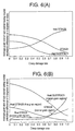
- a plurality of curved lines denoting the relation between creep damage rate and average grain size should be drawn at many levels of stress to formulate a series of maps, that is a 3D map made by stacking a plurality of graphical drawings shown in Fig. 6 for a plurality levels of stress.
- a curved line in one of drawings is preferably selected for the corresponding stress or two curved lines in Fig. 6(A) and Fig. 6(B) are preferably interpolated to find a curved line of the corresponding stress.
- the map is substantially a set of working curves of creep damage extent vs. sub crystal grain size prepared for each prescribed stress.
- a curved line is selected from the working curves of the map or a curved line is made by interpolating two curved lines with regard to a loaded stress of an evaluated part. The creep damage of the part is found from thus sought curved line.
- the apparatus comprises a measuring means for measuring particle size variation behavior of crystal grains or sub grains having a crystal orientation difference of about about 2 degrees or more, preferably 3 degrees or more with regard to a specimen at an evaluated part of high tension heat resistant steel and a working curve or a working map prepared in advance by looking for the relation of the grain sizes with respect to the creep damage extents (including creep damage rates) at every level of loaded stress wherein a creep damage extent is capably evaluated by comparing the grain size variation behavior measured by the measuring means with a working curve or a working map selected on the basis of a loaded stress.
- an electron beam is irradiated on said specimen, from whom TEM-Kikuchi pattern appears by the irradiation, the pattern being taken into a TV camera coated with phosphoric acid on its surface to observe and analyze it.
- the map is preferably a 3D map made by stacking a plurality of working curve charts denoting a relation of creep damage extents and average grain sizes for a plurality of prescribed levels of stress.
- base metal of steel tubes of heat exchanging boilers for thermal power plant boilers were used for test specimens. More specifically, materials are two kinds of ferritic steels and one kind of austenite stainless steel, details being described as follows.
- Test specimens were taken from the three kinds of sample material of the base metal and welding joints. That is, creep test specimens shown in Fig. 2(A) and Fig. 2(B) were cut out from base metal part and welding part respectively by grind-cutting operation.
- Creep testing was conducted under the following conditions: 550 °C ⁇ 110 MPa for base metal and welding joints of 1A, STBA20; 600 °C ⁇ 130 MPa for base metal and welding joints of 1B, Heat STBA28; 650 °C ⁇ 130 MPa for base metal and welding joints of 2, heat SUSTP347H.
- Crystal orientation analyzing was made by a known EBDP (Electron Backscatter Diffraction Pattern) method.
- EBSP method has an accuracy of; a spacial resolution of 0.1 ⁇ m, a measuring depth of 0.05 ⁇ m, an angle range of ⁇ 40° ,and a bearing accuracy of 0.5°.
- the method has high spacial resolution in comparison to ECP (Electron Channeling Pattern) method though spacial resolution and bearing accuracy are inferior to those of TEM/ Kikuchi line method.
- a SEM is shown in Fig.
- the method has distinguishing characteristics such as facile preparation of specimens and overwhelmingly quick affixing of index numbers because bulk specimens can be observed.
- An orientation angle difference of adjacent crystal grains or sub grains can be evaluated quantitatively.
- An average grain size is estimated by regarding an interface having a crystal orientation difference of about 2 degrees or more, preferably 3 degrees or more in the crystal orientation images obtained by the SEM as a boundary. Fine crystals having a comparatively small orientation angel of adjacent crystals in a cluster of old austenite grains having a comparatively large orientation angle are herein referred to as sub crystal grains.
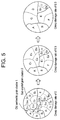
- Fig. 4 and Fig. 5 are pattern diagrams showing structure changes of the sub crystal grains accompanied by creep damage.
- Fig. 4 is a pattern diagrams showing crystal changes of base metal of STBA24 and heat SUSTP347H, a part influenced by welding heat of heat STBA28 (a fine grain region), and a part influenced by welding heat of heat SUSTP347H (a coarse grain region). It can be seen that an average grain size becomes smaller as sub crystal grain clusters 2 are formed in an old austenite crystal grain cluster 1 with the increasing ratio of creep damages, 0 ⁇ 0.5 ⁇ 0.9.
- Fig. 5 is a pattern diagrams showing crystal changes of a part influenced by welding heat of STBA24 (a coarse grain region), and base metal and a part influenced by welding heat of heat STBA28 (a coarse grain region). It can be seen that an average grain size becomes larger as sub crystal grain clusters 2 are decreased in an old austenite crystal grain cluster 1 with the increasing ratio of creep damages, 0 ⁇ 0.5 ⁇ 0.9.
- Martensite and bainite lath which have the same characteristics as a sub grain cluster were also regarded as a sub grain.
- Crystal orientation differences and average grain sizes of adjacent crystals of old austenite grain cluster 1 (A-D) and sub grain cluster 2 (A 1 -D 3 , A 1.1 -D 3 ) accompanied by creep damage in base metal(2.25Cr-1Mo) of STBA24 are shown in Table 2.
- Crystal orientation differences and average grain sizes of adjacent crystals of old austenite grain cluster 1(A-H) and sub grain cluster 2 (A 1 -G 1 ) accompanied by creep damage in heat STBA28 are shown in Table 3.
- a sub grain cluster 2 is referred to as a grain cluster of small crystal orientation difference
- an old austenite grain cluster is referred to as a large oblique angle grain cluster, generally of a big crystal orientation difference.
- Fig. 6(A) illustrates that an average grain size becomes smaller as creep damage proceeds in base material of STBA24 and heat SUSTP347H but instead, it becomes larger in base material of heat STBA28, which is denoted by the curve.
- Fig. 6(B) illustrates that an average grain size becomes larger as creep damage proceeds in a coarse grain region of a part influenced by welding heat of STBA24 and heat STBA28 and an average grain size turns finer in comparison to that before creep damage in a coarse grain region of a part influenced by welding heat of heat STBA28 and heat SUSTP347H.
- the curves denoting the relation of creep damage rate to average grain size are preferably prepared for a plurality levels of stress, levels having a prescribed breadth therebetween and integrated to a map such as a 3D map to which a plurality of graph charts shown in Fig. 6 for a plurality levels of stress are stacked.
- a time consuming destructive test which is known to be a reliable evaluation method, is not necessary but a creep damage evaluation having the same precision as a destructive test can be conducted for a very short time. Therefore, a life at a high-pressure part of a power plant incurred by creep damage is precisely evaluated so as to estimate accurately the rest of the life of the power plant, which results in improving plant reliability.
- Creep damage rate Crystal Crystal orientation difference Average grain size( ⁇ m) 0 A ⁇ D 20° or more 103 0.3 A 1 ⁇ D 3 3° or more 37 39 B 1 ⁇ B 4 3° or more 41 C 1 ⁇ C 4 3° or more 39 D 1 ⁇ D 3 3° or more 37 0.9 A 1-1 ⁇ A 1-2 ⁇ A 2 ⁇ A 3-2 3° or more 20 21 B 1-1 ⁇ B 3 ⁇ B 4-3 3° of more 18 C 1 ⁇ C 2-1 ⁇ C 4 3° or more 23 D 1-1 ⁇ D 2-1 ⁇ D 3 3° or more 19 Creep damage rate Crystal Crystal Crystal orientation difference Average grain size( ⁇ m) 0 A 1 ⁇ B 3 3° or more 22 24 C 1-1 ⁇ D 2 3° or more 23 E 1-1 ⁇ F 2 3° or more 24 G 1 ⁇ H 3° or more 30 0.5 A ⁇ B 3° or more 51 39 C 1 ⁇ D 2 3° or more 31 E 1 ⁇ F 3° or more 37 G 1 ⁇ H 3° or
Landscapes
- Life Sciences & Earth Sciences (AREA)
- Chemical & Material Sciences (AREA)
- General Health & Medical Sciences (AREA)
- General Physics & Mathematics (AREA)
- Pathology (AREA)
- Physics & Mathematics (AREA)
- Health & Medical Sciences (AREA)
- Immunology (AREA)
- Analytical Chemistry (AREA)
- Biochemistry (AREA)
- Ecology (AREA)
- Biodiversity & Conservation Biology (AREA)
- Environmental & Geological Engineering (AREA)
- Environmental Sciences (AREA)
- Dispersion Chemistry (AREA)
- Investigating And Analyzing Materials By Characteristic Methods (AREA)
- Analysing Materials By The Use Of Radiation (AREA)
- Testing Of Devices, Machine Parts, Or Other Structures Thereof (AREA)
- Testing Resistance To Weather, Investigating Materials By Mechanical Methods (AREA)
- Investigating Strength Of Materials By Application Of Mechanical Stress (AREA)
Abstract
Description
Heat STBA28 740°C×0.5h
Heat SUSTP347H none
A small piece was cut out from parallel part of a suspended creep test piece. The small piece was buried in resin in parallel with the direction of stress load, polished with till #1200 Emery paper and finally finished with 0.1 µm diamond paste to mirror surface. The polished surface was electro polished in 10% perchloric acid/ethanol solution with an applied voltage of approximately 15 volts to remove the processed layer.

| Creep damage rate | Crystal | Crystal orientation difference | Average grain size(µm) | |
| 0 | A∼D | 20° or more | 103 | |
| 0.3 | A1∼D3 | 3° or more | 37 | 39 |
| B1∼ | 3° or more | 41 | ||
| C1∼ | 3° or more | 39 | ||
| D1∼ | 3° or more | 37 | ||
| 0.9 | A1-1∼A1-2∼A2 ∼A3-2 | 3° or more | 20 | 21 |
| B1-1∼B3∼ | 3° of more | 18 | ||
| C1∼C2-1∼ | 3° or more | 23 | ||
| D1-1∼D2-1∼ | 3° or more | 19 |
| Creep damage rate | Crystal | Crystal orientation difference | Average grain size(µm) | |
| 0 | A1∼B3 | 3° or more | 22 | 24 |
| C1-1∼ | 3° or more | 23 | ||
| E1-1∼ | 3° or more | 24 | ||
| G1∼ | 3° or more | 30 | ||
| 0.5 | A∼ | 3° or more | 51 | 39 |
| C1∼ | 3° or more | 31 | ||
| E1∼ | 3° or more | 37 | ||
| G1∼ | 3° or more | 42 | ||
| 0.9 | A, | 3° or more | 52 | 52 |
| C, | 3° or more | 60 | ||
| E, | 3° or more | 58 | ||
| G1∼ | 3° or more | 42 |
Claims (8)
- A high-precision method for evaluating creep damage of heat resistant steel, comprising:comparing particle size behavior varying with creep damage progress of crystal grains or sub crystal grains having a crystal orientation difference of approximately 2 degrees or more at an evaluated part on the basis of a working curve or a working map prepared in advance by looking for the relation of grain sizes to creep damage extents including creep damage rates.
- The method according to claim 1, wherein creep damage is evaluated of base metal or of a part influenced by welding heat of high tension heat resistant steel used in high temperature exposing apparatuses.
- The method according to claim 1, wherein creep damage is evaluated of base metal, which is used in high temperature apparatuses, of ferritic steel and austenitic stainless steel having two phases structure of ferrite and pearlite, a part influenced by welding heat of ferritic heat resistant steel based on a tempered martensitic structure or a tempered bainite structure and having a fine grain region therein, or a part influenced by welding heat of austenitic stainless steel having a coarse grain region.
- The method according to claim 1, wherein creep damage is evaluated of a coarse grain region of a base metal of ferritic steel, a coarse grain region influenced by welding heat of ferritic heat resistant steel having a tempered martensitic structure or a tempered bainite structure or a coarse grain region influenced by welding heat of ferritic steel having two phases structure of ferrite and pearlite, wherein particle size behavior or preferably average particle size behavior is compared.
- The method according to claim 1, wherein the working map is substantially a set of working curves of creep damage extent vs. crystal grains or sub crystal grain size prepared for each prescribed stress and a curved line is selected from the working curves of the map or a curved line is made by interpolating two curved lines with regard to a loaded stress of an evaluated part and the creep damage of the part is found from thus sought curved line.
- A high-precision apparatus for evaluating creep damage of high tension heat resistant steel used in high temperature exposing apparatuses comprisinga measuring means for measuring particle size variation behavior, in accordance with creep damage progress, of crystal grains or sub grains having a crystal orientation difference of approximately 2 degrees or more with regard to a specimen at the evaluated part of high tension heat resistant steel anda working curve or a working map prepared in advance by looking for the relation of the grain sizes with respect to the creep damage extents including creep damage rates at every level of loaded stress wherein a creep damage extent is evaluated by comparing the grain size variation behavior, in accordance with creep damage progress, measured by the measuring means with a working curve or a working map selected on the basis of a loaded stress.
- The apparatus according to claim 6, wherein the measuring means is an apparatus comprising means for irradiating an electron beam on said specimen, which is mounted so that the electron beam is irradiated at a prescribed angle, from which a TEM-Kikuchi pattern appears by the irradiation, and a TV camera coated with phosphoric acid on its surface and adapted to take in the pattern to observe and analyze it.
- The apparatus according to claim 6 or 7, wherein the map is preferably a 3D map made by stacking a plurality of working curve charts denoting a relation of creep damage extents and average grain sizes for a plurality levels of stress.
Applications Claiming Priority (2)
| Application Number | Priority Date | Filing Date | Title |
|---|---|---|---|
| JP2001300988 | 2001-09-28 | ||
| JP2001300988A JP3643806B2 (en) | 2001-09-28 | 2001-09-28 | High-accuracy creep damage evaluation method |
Publications (2)
| Publication Number | Publication Date |
|---|---|
| EP1298431A2 true EP1298431A2 (en) | 2003-04-02 |
| EP1298431A3 EP1298431A3 (en) | 2004-02-18 |
Family
ID=19121471
Family Applications (1)
| Application Number | Title | Priority Date | Filing Date |
|---|---|---|---|
| EP02021873A Ceased EP1298431A3 (en) | 2001-09-28 | 2002-09-30 | High-precision method and apparatus for evaluating creep damage |
Country Status (6)
| Country | Link |
|---|---|
| US (1) | US6935552B2 (en) |
| EP (1) | EP1298431A3 (en) |
| JP (1) | JP3643806B2 (en) |
| KR (1) | KR100910424B1 (en) |
| CN (1) | CN100526848C (en) |
| CA (1) | CA2405387C (en) |
Cited By (2)
| Publication number | Priority date | Publication date | Assignee | Title |
|---|---|---|---|---|
| US6935552B2 (en) * | 2001-09-28 | 2005-08-30 | Mitsubishi Heavy Industries, Ltd. | High-precision method and apparatus for evaluating creep damage |
| CN110161060A (en) * | 2018-02-14 | 2019-08-23 | 三菱重工业株式会社 | Faulted condition decision maker and faulted condition determination method |
Families Citing this family (22)
| Publication number | Priority date | Publication date | Assignee | Title |
|---|---|---|---|---|
| WO2002014835A1 (en) * | 2000-08-16 | 2002-02-21 | The Chugoku Electric Power Co., Inc. | Method for evaluating creep lifetime |
| NL1023383C2 (en) * | 2003-05-09 | 2004-11-15 | Rexnord Flattop Europe Bv | Chain pin for hinge band chains. |
| JP4797509B2 (en) * | 2005-08-22 | 2011-10-19 | 株式会社Ihi | Destruction cause estimation apparatus and destruction cause estimation method |
| JP2007248390A (en) * | 2006-03-17 | 2007-09-27 | Ihi Corp | Breakage life evaluation device |
| JP5282519B2 (en) * | 2008-10-10 | 2013-09-04 | 新日鐵住金株式会社 | Crystal grain analysis apparatus, crystal grain analysis method, and computer program |
| JP4750868B2 (en) * | 2009-03-19 | 2011-08-17 | 株式会社日立製作所 | Remaining life diagnosis method for bolts used at high temperatures |
| FR2958037B1 (en) * | 2010-03-26 | 2025-01-10 | Sc2N Sa | TEMPERATURE SENSOR |
| EP2950041B1 (en) * | 2013-01-25 | 2018-06-20 | The Chugoku Electric Power Co., Inc. | System and method for distance measurement |
| CN105910921B (en) * | 2016-04-11 | 2018-08-10 | 沈阳工业大学 | A method of prediction DZ125 alloy creep curves |
| JP6913525B2 (en) * | 2017-06-15 | 2021-08-04 | 株式会社日立パワーソリューションズ | Creep damage evaluation method |
| CN108857132B (en) * | 2018-07-24 | 2021-04-20 | 哈尔滨工业大学(深圳) | A method for evaluating the reliability of lead-free solder joints |
| EP3736561B1 (en) * | 2019-05-08 | 2021-05-05 | Bruker Nano GmbH | Method for improving an ebsd/tkd map |
| CN110320117A (en) * | 2019-07-15 | 2019-10-11 | 泰州市金鹰精密铸造有限公司 | The test method of based single crystal blade croop property |
| CN110907475A (en) * | 2019-10-17 | 2020-03-24 | 上海发电设备成套设计研究院有限责任公司 | A Remaining Life Evaluation Method of Martensitic Heat Resistant Steel |
| CN110806357A (en) * | 2019-11-13 | 2020-02-18 | 中国石油大学(华东) | Method for evaluating high-temperature creep damage based on low-temperature fracture |
| CN113732555B (en) * | 2020-05-29 | 2022-09-20 | 宝山钢铁股份有限公司 | Low-carbon microalloyed steel weldability evaluation method based on low-hydrogen type welding rod manual welding |
| CN111879226B (en) * | 2020-08-03 | 2022-04-05 | 华东理工大学 | A furnace roll life evaluation method based on on-site metallography and roll surface deformation |
| CN111982946A (en) * | 2020-08-05 | 2020-11-24 | 鞍钢股份有限公司 | A method for determining the size of pearlite pellets and fields of high carbon steel wire rods |
| CN112098243B (en) * | 2020-08-19 | 2025-01-24 | 东莞市琦鑫五金有限公司 | A test and improvement method for creep characteristics of 409L stainless steel welded joints |
| CN112214875B (en) * | 2020-09-11 | 2022-03-22 | 东方电气集团东方汽轮机有限公司 | Method for evaluating real service temperature of workpiece through precipitated particle phase size |
| CN114486515B (en) * | 2021-12-15 | 2023-05-30 | 中国科学院金属研究所 | Vermicular cast iron fatigue strength prediction method based on microstructure and tensile property |
| CN116026278B (en) * | 2022-12-21 | 2025-10-31 | 湖南特种玻璃研究院有限公司 | Method for predicting service life of overflow brick |
Family Cites Families (22)
| Publication number | Priority date | Publication date | Assignee | Title |
|---|---|---|---|---|
| US4287417A (en) | 1979-01-31 | 1981-09-01 | Tokyo Shibaura Denki Kabushiki Kaisha | Method of determining the deterioration of heat-resistant ferritic steel parts |
| JPS5629142A (en) | 1979-08-20 | 1981-03-23 | Toshiba Corp | Measuring method of deterioration degree of ferrite heat-resisting steel |
| JPS5744841A (en) | 1980-09-01 | 1982-03-13 | Hitachi Ltd | Method and apparatus for x-ray diffraction |
| JPS57141556A (en) | 1981-02-25 | 1982-09-01 | Toshiba Corp | Evaluating method for deterioration degree of heat resisting low alloy steel |
| JPS5960347A (en) | 1982-09-30 | 1984-04-06 | Toshiba Corp | Method for evaluating deterioration degree of low-alloy heat-resistant steel |
| JPH03209162A (en) | 1990-01-11 | 1991-09-12 | Toshiba Corp | Method for estimating deterioration of heat resisting steel |
| JP2706354B2 (en) * | 1990-06-26 | 1998-01-28 | 三菱重工業株式会社 | Evaluation method for creep damage of heat resistant ferritic steel |
| US5383874A (en) * | 1991-11-08 | 1995-01-24 | Ep Technologies, Inc. | Systems for identifying catheters and monitoring their use |
| US5573172A (en) * | 1993-11-08 | 1996-11-12 | Sawtek, Inc. | Surface mount stress relief hidden lead package device and method |
| US5651493A (en) * | 1995-04-24 | 1997-07-29 | International Business Machines Corporation | Method of performing solder joint analysis of semi-conductor components |
| JPH0972897A (en) * | 1995-09-05 | 1997-03-18 | Babcock Hitachi Kk | Life evaluating method by creep cavity |
| US6017354A (en) * | 1996-08-15 | 2000-01-25 | Stryker Corporation | Integrated system for powered surgical tools |
| JP3334070B2 (en) | 1996-10-22 | 2002-10-15 | 株式会社日立製作所 | A method for estimating creep life of hot parts for gas turbines. |
| JPH10170503A (en) | 1996-12-13 | 1998-06-26 | Mitsubishi Heavy Ind Ltd | Evaluation method for creep life of tempered martensite heat-resisting steel |
| JP3976938B2 (en) * | 1999-03-05 | 2007-09-19 | 中国電力株式会社 | Creep life evaluation method |
| DE19950313A1 (en) | 1999-10-14 | 2001-04-19 | Ver Energiewerke Ag | Process for testing metallic material e.g., martensitic chromium steel comprises finely polishing surface, developing fine structure electrolytically by current potential etching, fixing the surface with foil print, removing and evaluating |
| KR100441414B1 (en) * | 2000-04-21 | 2004-07-23 | 신닛뽄세이테쯔 카부시키카이샤 | High fatigue strength steel sheet excellent in burring workability and method for producing the same |
| KR100374697B1 (en) * | 2000-05-09 | 2003-03-04 | 유효선 | Small punch-creep tester and evaluating method of creep characteristics for high temperature structural components |
| WO2002014835A1 (en) * | 2000-08-16 | 2002-02-21 | The Chugoku Electric Power Co., Inc. | Method for evaluating creep lifetime |
| JP4153675B2 (en) * | 2001-04-10 | 2008-09-24 | 三菱重工業株式会社 | Material life evaluation system and evaluation method |
| JP3643806B2 (en) * | 2001-09-28 | 2005-04-27 | 三菱重工業株式会社 | High-accuracy creep damage evaluation method |
| KR20030046277A (en) * | 2001-12-05 | 2003-06-12 | 유효선 | Creep properties evaluation technique for heat resistant steel weldment using miniaturize specimen |
-
2001
- 2001-09-28 JP JP2001300988A patent/JP3643806B2/en not_active Expired - Fee Related
-
2002
- 2002-09-26 CA CA2405387A patent/CA2405387C/en not_active Expired - Lifetime
- 2002-09-27 US US10/256,137 patent/US6935552B2/en not_active Expired - Lifetime
- 2002-09-28 CN CNB021482071A patent/CN100526848C/en not_active Expired - Fee Related
- 2002-09-28 KR KR1020020059117A patent/KR100910424B1/en not_active Expired - Fee Related
- 2002-09-30 EP EP02021873A patent/EP1298431A3/en not_active Ceased
Non-Patent Citations (2)
| Title |
|---|
| KOTA SAWADA ET AL: "Residual Creep Life Assessment by Change of Martensitic Lath Structure in Modified 9Cr-1Mo Steels", JOURNAL OF THE IRON STEEL INSTITUTE OF JAPAN, vol. 84, no. 8, 1 January 1998 (1998-01-01), pages 40 - 45, XP055086163 * |
| SAWADA K ET AL: "Dislocation Substructure Degradation during Creep of Martensitic Heat-resisting Steels with and without W", MATERIALS FOR ADVANCED POWER ENGINEERING. PROCEEDINGS OF THE 6TH LI GBP EGE CONFERENCE ON MATERIALS FOR ADVANCED POWER ENGINEERING, 5.-7. OCT. 1998,, vol. 5, no. 1, 5 October 1998 (1998-10-05), pages 575 - 583, XP009173389, ISBN: 978-3-89336-228-8 * |
Cited By (2)
| Publication number | Priority date | Publication date | Assignee | Title |
|---|---|---|---|---|
| US6935552B2 (en) * | 2001-09-28 | 2005-08-30 | Mitsubishi Heavy Industries, Ltd. | High-precision method and apparatus for evaluating creep damage |
| CN110161060A (en) * | 2018-02-14 | 2019-08-23 | 三菱重工业株式会社 | Faulted condition decision maker and faulted condition determination method |
Also Published As
| Publication number | Publication date |
|---|---|
| US20030062397A1 (en) | 2003-04-03 |
| KR20030027864A (en) | 2003-04-07 |
| CA2405387C (en) | 2010-04-20 |
| JP3643806B2 (en) | 2005-04-27 |
| US6935552B2 (en) | 2005-08-30 |
| CN1409099A (en) | 2003-04-09 |
| CA2405387A1 (en) | 2003-03-28 |
| EP1298431A3 (en) | 2004-02-18 |
| KR100910424B1 (en) | 2009-08-04 |
| JP2003107019A (en) | 2003-04-09 |
| CN100526848C (en) | 2009-08-12 |
Similar Documents
| Publication | Publication Date | Title |
|---|---|---|
| US6935552B2 (en) | High-precision method and apparatus for evaluating creep damage | |
| Kamaya et al. | Measurement of plastic strain of polycrystalline material by electron backscatter diffraction | |
| Shen et al. | Overcoming the drawbacks of plastic strain estimation based on KAM | |
| Ma et al. | The mixed-mode investigation of the fatigue crack in CTS metallic specimen | |
| Dong et al. | Microstructure and sulfide stress corrosion cracking of the Inconel 625/X80 weld overlay fabricated by cold metal transfer process | |
| Que et al. | Effect of machining on near surface microstructure and the observation of martensite at the fatigue crack tip in PWR environment of 304L stainless steel | |
| Bai et al. | Investigation of hydrogen embrittlement in welded joints of the L360MH pipeline steel for hydrogen transportation | |
| Ben Salem et al. | Mechanical behavior characterization of a stainless steel dissimilar metal weld interface: in-situ micro-tensile testing on carburized martensite and austenite | |
| Mariappan et al. | Characterization of the cyclic deformation behavior of simulated HAZs and other constituent microstructural regions of P91 steel weldment | |
| Benzing et al. | Tracking defects and microstructural heterogeneities in meso-scale tensile specimens excised from additively manufactured parts | |
| Benzing et al. | Quasi-static and dynamic fracture toughness of 316L stainless steel welds at cryogenic temperatures | |
| JP3121953B2 (en) | Method for detecting carbide in low alloy steel by electrochemical polarization method | |
| Blaszkiewicz et al. | The eddy current technique for determining residual stresses in steels | |
| JP3486315B2 (en) | High temperature damage evaluation method for tempered martensitic steel | |
| Alabdullah | Machinability analysis of super austenitic stainless steel | |
| Brewer et al. | Comparison of diffraction methods for measurement of surface damage in superalloys | |
| Kitade et al. | Clarification of micromechanism on Brittle Fracture Initiation Condition of TMCP Steel with MA as the trigger point | |
| Viswanathan et al. | Etching technique for assessing toughness degradation of in-service components | |
| Saukkonen et al. | Plastic strain and residual stress distributions in an AISI 304 stainless steel BWR pipe weld | |
| Zumpano Jr et al. | Susceptibility to preferential corrosion of pipeline welded joints in condensed and dragged water droplet-part 1 | |
| Masoumi et al. | Comparative analysis of microstructural influences on cracking in pearlitic reinforced rods steels with spheroidized vs. lamellar cementite configurations in harsh environments | |
| JP7277729B2 (en) | Precipitate Identification Method, Precipitate Information Acquisition Method and Program | |
| Byron | Corrosion Behaviors of API 5 L Carbon steel Pipelines in Trinidad's Soil Environment | |
| Whitt et al. | Fundamental Understanding of Creep-Fatigue Interactions in 9Cr-1MoV Steel Welds. Final Report | |
| Conejo et al. | Nondestructive evaluation of corrosion in an artificial aging process at a clad pipe by thermoelectric means |
Legal Events
| Date | Code | Title | Description |
|---|---|---|---|
| PUAI | Public reference made under article 153(3) epc to a published international application that has entered the european phase |
Free format text: ORIGINAL CODE: 0009012 |
|
| 17P | Request for examination filed |
Effective date: 20020930 |
|
| AK | Designated contracting states |
Kind code of ref document: A2 Designated state(s): AT BE BG CH CY CZ DE DK EE ES FI FR GB GR IE IT LI LU MC NL PT SE SK TR Designated state(s): AT BE BG CH CY CZ DE DK EE ES FI FR GB GR IE IT LI LU MC NL PT SE SK TR |
|
| AX | Request for extension of the european patent |
Extension state: AL LT LV MK RO SI |
|
| PUAL | Search report despatched |
Free format text: ORIGINAL CODE: 0009013 |
|
| AK | Designated contracting states |
Kind code of ref document: A3 Designated state(s): AT BE BG CH CY CZ DE DK EE ES FI FR GB GR IE IT LI LU MC NL PT SE SK TR |
|
| AX | Request for extension of the european patent |
Extension state: AL LT LV MK RO SI |
|
| AKX | Designation fees paid |
Designated state(s): DE FR GB |
|
| 17Q | First examination report despatched |
Effective date: 20050701 |
|
| R17C | First examination report despatched (corrected) |
Effective date: 20050701 |
|
| STAA | Information on the status of an ep patent application or granted ep patent |
Free format text: STATUS: THE APPLICATION HAS BEEN REFUSED |
|
| 18R | Application refused |
Effective date: 20131108 |