EP1298402B1 - Device for use as a chemical reactor or heat exchanger with a tube plate - Google Patents
Device for use as a chemical reactor or heat exchanger with a tube plate Download PDFInfo
- Publication number
- EP1298402B1 EP1298402B1 EP02256819.0A EP02256819A EP1298402B1 EP 1298402 B1 EP1298402 B1 EP 1298402B1 EP 02256819 A EP02256819 A EP 02256819A EP 1298402 B1 EP1298402 B1 EP 1298402B1
- Authority
- EP
- European Patent Office
- Prior art keywords
- heat exchanger
- tube plate
- chemical reactor
- plate
- general
- Prior art date
- Legal status (The legal status is an assumption and is not a legal conclusion. Google has not performed a legal analysis and makes no representation as to the accuracy of the status listed.)
- Expired - Lifetime
Links
- 239000000126 substance Substances 0.000 title claims description 19
- 239000012530 fluid Substances 0.000 description 3
- 238000010276 construction Methods 0.000 description 2
- 238000009434 installation Methods 0.000 description 2
- 230000002787 reinforcement Effects 0.000 description 2
- 238000005728 strengthening Methods 0.000 description 2
- 238000006243 chemical reaction Methods 0.000 description 1
- 238000003780 insertion Methods 0.000 description 1
- 230000037431 insertion Effects 0.000 description 1
- 230000014759 maintenance of location Effects 0.000 description 1
- 238000000034 method Methods 0.000 description 1
- 230000000717 retained effect Effects 0.000 description 1
Images
Classifications
-
- F—MECHANICAL ENGINEERING; LIGHTING; HEATING; WEAPONS; BLASTING
- F28—HEAT EXCHANGE IN GENERAL
- F28D—HEAT-EXCHANGE APPARATUS, NOT PROVIDED FOR IN ANOTHER SUBCLASS, IN WHICH THE HEAT-EXCHANGE MEDIA DO NOT COME INTO DIRECT CONTACT
- F28D9/00—Heat-exchange apparatus having stationary plate-like or laminated conduit assemblies for both heat-exchange media, the media being in contact with different sides of a conduit wall
-
- F—MECHANICAL ENGINEERING; LIGHTING; HEATING; WEAPONS; BLASTING
- F28—HEAT EXCHANGE IN GENERAL
- F28D—HEAT-EXCHANGE APPARATUS, NOT PROVIDED FOR IN ANOTHER SUBCLASS, IN WHICH THE HEAT-EXCHANGE MEDIA DO NOT COME INTO DIRECT CONTACT
- F28D7/00—Heat-exchange apparatus having stationary tubular conduit assemblies for both heat-exchange media, the media being in contact with different sides of a conduit wall
- F28D7/16—Heat-exchange apparatus having stationary tubular conduit assemblies for both heat-exchange media, the media being in contact with different sides of a conduit wall the conduits being arranged in parallel spaced relation
-
- F—MECHANICAL ENGINEERING; LIGHTING; HEATING; WEAPONS; BLASTING
- F28—HEAT EXCHANGE IN GENERAL
- F28F—DETAILS OF HEAT-EXCHANGE AND HEAT-TRANSFER APPARATUS, OF GENERAL APPLICATION
- F28F9/00—Casings; Header boxes; Auxiliary supports for elements; Auxiliary members within casings
- F28F9/02—Header boxes; End plates
Definitions
- the present invention relates to a device used as a chemical reactor or heat exchanger in general, with a thin tube plate.
- the present invention also applies to petrochemical and refinery reactors.
- EP 0 660 063 A2 discloses providing reinforcement in a tank of a heat exchanger to prevent the tank from being expanded outwardly against the inner pressure of the heat exchanger.
- the document discloses the features of the preamble of claim 1.
- chemical reactors consist of large-sized containers, inside which chemical reactions take place at a high temperature and high pressure.
- these chemical reactors generally have a plurality of pipes or tube bundles which can carry out various functions, including heat exchange between the operating fluids.
- tube bundles are installed and retained in the operative position by means of the use of tube plates, which in some cases can have a large surface area.
- the tube plates are produced in a single piece, or alternatively in several welded pieces, and are then finished, for example they are drilled and/or machined.
- the tube plates are usually designed with a thickness which makes it possible to withstand the loads applicable.
- these plates can alternatively be produced with a reduced thickness, but with the addition of elements which are used to strengthen the plates themselves.
- Design codes are also known which regulate the dimensional criteria for the plates and for strengthening the latter.
- the known strengtheners consist of reinforcement ribs, which are welded to the thin plates such as to limit the deformations and stresses to which the plates are subjected.
- the present invention thus seeks to eliminate the aforementioned disadvantages and in particular to provide a device which is used as a chemical reactor or heat exchanger in general, with a thin tube plate, which makes it possible to reduce the costs of construction of the device itself.
- the present invention also seeks to provide a device which is used as a chemical reactor or heat exchanger in general, with a thin tube plate, which makes it possible to lighten the device itself and facilitate its installation.
- the present invention further seeks to provide a device used as a chemical reactor or heat exchanger in general, with a thin tube plate, which is safe and reliable when it is installed.
- the present invention still further seeks to provide a device used as a chemical reactor or heat exchanger in general, with a thin tube plate, which is particularly simple and functional.
- a device used as a chemical reactor or heat exchanger in general with a thin tube plate, of the type in which at least one pipe is connected to a tube plate, the said tube plate being connected to a chamber, wherein this chamber is produced by means of a section, with a base which is joined to the plate by a lateral portion, characterised in that connection elements are provided between the said tube plate and the said base of the said chamber.
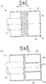
- Figure 1 shows a device used as a chemical reactor or heat exchanger in general, indicated as 10 as a whole, according to the known art.
- the device 10 comprises a pipe system 12.
- This system in preferred embodiments described by way of non-limiting example, comprises pipes which are superimposed and is secured to a tube plate 14 disposed perpendicularly to the axis of the pipes.
- a chamber 16 which acts as a fluid distributor is connected to the tube plate 14.
- this chamber 16 is produced by means of a section in the shape of a "U”, with a base 18 which is joined to the plate 14 by a cylindrical portion 20, with generatrices parallel to the axis of the pipes.
- figure 2 shows a device used as a chemical reactor or heat exchanger in general, indicated as 110 as a whole, according to the present invention.
- figure 2 shows a device used as a chemical reactor or heat exchanger in general, indicated as 110 as a whole, according to the present invention.
- the device 110 comprises a pipe system 112 which is shown schematically in the figure.
- this system 112 comprises pipes which are superimposed and is secured to a tube plate 114 disposed perpendicularly to the axis of the pipes.
- a chamber 116 which acts as a fluid distributor is connected to the tube plate 114.
- the chamber 116 is produced by means of a section in the shape of a "U”, with a base 118 which is joined to the plate 114 by a cylindrical or lateral portion 120, with generatrices parallel to the axis of the pipes.
- the plate 114 of the device 110 according to the invention is connected at the base 118 of the chamber 116 both by means of the cylindrical portion 120 and by means of connection elements 122 which are disposed inside the cylindrical portion 120.
- connection elements 122 are cylindrical or flat portions with a shape similar to the lateral portion 120.
- the example shows one of these elements 122, disposed axially symmetrically relative to the axis of the pipe 112, although other configurations are not excluded.
- the loads are transmitted entirely by the device 10 through the plate 14 to the cylindrical portion 20 of the chamber 16.
- the loads are transmitted by the device 110 through the plate 114, both to the cylindrical portion 120 and to the connection elements 122.
- the invention can be applied to chemical reactors, petrochemical reactors, refinery reactors, heat exchangers, and in general to tube bundle-type pressure devices.
Landscapes
- Engineering & Computer Science (AREA)
- Physics & Mathematics (AREA)
- Thermal Sciences (AREA)
- Mechanical Engineering (AREA)
- General Engineering & Computer Science (AREA)
- Heat-Exchange Devices With Radiators And Conduit Assemblies (AREA)
- Physical Or Chemical Processes And Apparatus (AREA)
- Catalysts (AREA)
Applications Claiming Priority (2)
| Application Number | Priority Date | Filing Date | Title |
|---|---|---|---|
| ITMI20012034 | 2001-10-01 | ||
| IT2001MI002034A ITMI20012034A1 (it) | 2001-10-01 | 2001-10-01 | Apparecchio utilizzato come reattore chimico o scambiatore di calore in genere con piastra tubiera sottile |
Publications (2)
| Publication Number | Publication Date |
|---|---|
| EP1298402A1 EP1298402A1 (en) | 2003-04-02 |
| EP1298402B1 true EP1298402B1 (en) | 2019-08-07 |
Family
ID=11448457
Family Applications (1)
| Application Number | Title | Priority Date | Filing Date |
|---|---|---|---|
| EP02256819.0A Expired - Lifetime EP1298402B1 (en) | 2001-10-01 | 2002-10-01 | Device for use as a chemical reactor or heat exchanger with a tube plate |
Country Status (10)
Families Citing this family (1)
| Publication number | Priority date | Publication date | Assignee | Title |
|---|---|---|---|---|
| RU2516998C2 (ru) * | 2012-04-05 | 2014-05-27 | Федеральное государственное бюджетное образовательное учреждение высшего профессионального образования "Казанский национальный исследовательский технический университет им. А.Н. Туполева-КАИ" (КНИТУ-КАИ) | Кожухотрубный теплообменник |
Family Cites Families (5)
| Publication number | Priority date | Publication date | Assignee | Title |
|---|---|---|---|---|
| US3863713A (en) * | 1973-08-27 | 1975-02-04 | Stewart Warner Corp | Heat exchanger |
| DE3006900C2 (de) * | 1980-02-23 | 1982-07-01 | Davy McKee AG, 6000 Frankfurt | Vorrichtung zur Durchführung der katalytischen Oxidation gasförmiger Schwefelverbindungen zu Schwefeltrioxid |
| US5266281A (en) * | 1989-09-16 | 1993-11-30 | Xytel Technologies Partnership | Catalytic reactor |
| JPH07180988A (ja) * | 1993-12-21 | 1995-07-18 | Sanden Corp | 熱交換器 |
| RU2080914C1 (ru) * | 1994-04-11 | 1997-06-10 | Акционерное общество открытого типа "Уфанефтехим" | Кожухотрубчатый реактор |
-
2001
- 2001-10-01 IT IT2001MI002034A patent/ITMI20012034A1/it unknown
-
2002
- 2002-09-26 CA CA002405315A patent/CA2405315C/en not_active Expired - Lifetime
- 2002-09-30 RO ROA200201254A patent/RO121237B1/ro unknown
- 2002-09-30 US US10/259,801 patent/US6858191B2/en not_active Expired - Lifetime
- 2002-09-30 JP JP2002284667A patent/JP4357824B2/ja not_active Expired - Fee Related
- 2002-09-30 CN CN02152920A patent/CN1409082A/zh active Pending
- 2002-09-30 KR KR1020020059344A patent/KR100904793B1/ko not_active Expired - Fee Related
- 2002-09-30 RU RU2002125937/12A patent/RU2316389C2/ru active
- 2002-09-30 CN CN201010157066A patent/CN101837271A/zh active Pending
- 2002-10-01 EP EP02256819.0A patent/EP1298402B1/en not_active Expired - Lifetime
- 2002-10-01 ES ES02256819T patent/ES2751990T3/es not_active Expired - Lifetime
Non-Patent Citations (1)
| Title |
|---|
| None * |
Also Published As
| Publication number | Publication date |
|---|---|
| CN101837271A (zh) | 2010-09-22 |
| EP1298402A1 (en) | 2003-04-02 |
| KR100904793B1 (ko) | 2009-06-25 |
| US20030086843A1 (en) | 2003-05-08 |
| JP2003176994A (ja) | 2003-06-27 |
| CN1409082A (zh) | 2003-04-09 |
| JP4357824B2 (ja) | 2009-11-04 |
| US6858191B2 (en) | 2005-02-22 |
| RU2316389C2 (ru) | 2008-02-10 |
| RO121237B1 (ro) | 2007-01-30 |
| ES2751990T3 (es) | 2020-04-02 |
| CA2405315C (en) | 2009-11-10 |
| ITMI20012034A0 (it) | 2001-10-01 |
| KR20030028421A (ko) | 2003-04-08 |
| ITMI20012034A1 (it) | 2003-04-01 |
| CA2405315A1 (en) | 2003-04-01 |
Similar Documents
| Publication | Publication Date | Title |
|---|---|---|
| AU2003225596B2 (en) | Method and apparatus for minimizing adverse effects of thermal expansion in a heat exchange reactor | |
| EP1624273B1 (en) | Method of forming a laminated tubesheet | |
| US4210199A (en) | Heat exchange system | |
| WO2017100521A1 (en) | Heat exchangers | |
| EP0245848A1 (en) | Heat exchanger apparatus | |
| US4305453A (en) | Slide guide for tube-type heat exchanger | |
| CA2643156A1 (en) | Heat transfer tube support structure | |
| US6997141B2 (en) | Anti-vibration support for steam generator heat transfer tubes and method for making same | |
| EP1298402B1 (en) | Device for use as a chemical reactor or heat exchanger with a tube plate | |
| CA2702371C (en) | Tube support structure | |
| EP1624272B1 (en) | Tube support | |
| US4174123A (en) | Vessel penetration apparatus | |
| EP3399270B1 (en) | A plate heat exchanger | |
| CN111081397B (zh) | 一种一体化核反应堆一回路换热器 | |
| EP0113344B1 (en) | Heat exchangers and methods of construction thereof | |
| CA2456865C (en) | Device for introducing hot gas into a heating surface pipe of a waste heat boiler | |
| Oh et al. | Design option of heat exchanger for the next generation nuclear plant | |
| EP0277171B1 (en) | Plate heat exchanger with threaded connection ports | |
| EP4281724B1 (en) | Tube heat exchanger | |
| CN218469633U (zh) | 一种蒸发器管系折流板固定结构及预热器 | |
| GB2109531A (en) | Shell- and tube-type heat exchangers and their production | |
| EP4509793A1 (en) | Shell member for heat exchanger | |
| JPS6042292Y2 (ja) | 熱交換器 | |
| Baldina | Standard Methods of Hydraulic Design for Power Boilers | |
| GB2142716A (en) | Shell- and tube-type heat exchangers |
Legal Events
| Date | Code | Title | Description |
|---|---|---|---|
| PUAI | Public reference made under article 153(3) epc to a published international application that has entered the european phase |
Free format text: ORIGINAL CODE: 0009012 |
|
| AK | Designated contracting states |
Kind code of ref document: A1 Designated state(s): AT BE BG CH CY CZ DE DK EE ES FI FR GB GR IE IT LI LU MC NL PT SE SK TR Designated state(s): AT BE BG CH CY CZ DE DK EE ES FI FR GB GR IE IT LI LU MC NL PT SE SK TR |
|
| AX | Request for extension of the european patent |
Extension state: AL LT LV MK RO SI |
|
| 17P | Request for examination filed |
Effective date: 20031002 |
|
| AKX | Designation fees paid |
Designated state(s): DE ES FR |
|
| GRAP | Despatch of communication of intention to grant a patent |
Free format text: ORIGINAL CODE: EPIDOSNIGR1 |
|
| INTG | Intention to grant announced |
Effective date: 20190108 |
|
| RIC1 | Information provided on ipc code assigned before grant |
Ipc: F28D 7/16 20060101AFI20030122BHEP Ipc: F28F 9/02 20060101ALI20030122BHEP |
|
| GRAS | Grant fee paid |
Free format text: ORIGINAL CODE: EPIDOSNIGR3 |
|
| GRAA | (expected) grant |
Free format text: ORIGINAL CODE: 0009210 |
|
| AK | Designated contracting states |
Kind code of ref document: B1 Designated state(s): DE ES FR |
|
| REG | Reference to a national code |
Ref country code: DE Ref legal event code: R096 Ref document number: 60249966 Country of ref document: DE |
|
| REG | Reference to a national code |
Ref country code: ES Ref legal event code: FG2A Ref document number: 2751990 Country of ref document: ES Kind code of ref document: T3 Effective date: 20200402 |
|
| REG | Reference to a national code |
Ref country code: DE Ref legal event code: R119 Ref document number: 60249966 Country of ref document: DE |
|
| PLBE | No opposition filed within time limit |
Free format text: ORIGINAL CODE: 0009261 |
|
| STAA | Information on the status of an ep patent application or granted ep patent |
Free format text: STATUS: NO OPPOSITION FILED WITHIN TIME LIMIT |
|
| PG25 | Lapsed in a contracting state [announced via postgrant information from national office to epo] |
Ref country code: DE Free format text: LAPSE BECAUSE OF NON-PAYMENT OF DUE FEES Effective date: 20200501 |
|
| 26N | No opposition filed |
Effective date: 20200603 |
|
| PG25 | Lapsed in a contracting state [announced via postgrant information from national office to epo] |
Ref country code: FR Free format text: LAPSE BECAUSE OF NON-PAYMENT OF DUE FEES Effective date: 20191007 |
|
| PGFP | Annual fee paid to national office [announced via postgrant information from national office to epo] |
Ref country code: ES Payment date: 20201102 Year of fee payment: 19 |
|
| REG | Reference to a national code |
Ref country code: ES Ref legal event code: FD2A Effective date: 20221125 |
|
| PG25 | Lapsed in a contracting state [announced via postgrant information from national office to epo] |
Ref country code: ES Free format text: LAPSE BECAUSE OF NON-PAYMENT OF DUE FEES Effective date: 20211002 |