EP1298398A2 - Method and apparatus for freezing products - Google Patents
Method and apparatus for freezing products Download PDFInfo
- Publication number
- EP1298398A2 EP1298398A2 EP02256798A EP02256798A EP1298398A2 EP 1298398 A2 EP1298398 A2 EP 1298398A2 EP 02256798 A EP02256798 A EP 02256798A EP 02256798 A EP02256798 A EP 02256798A EP 1298398 A2 EP1298398 A2 EP 1298398A2
- Authority
- EP
- European Patent Office
- Prior art keywords
- belt
- surface area
- per square
- square meter
- tunnel
- Prior art date
- Legal status (The legal status is an assumption and is not a legal conclusion. Google has not performed a legal analysis and makes no representation as to the accuracy of the status listed.)
- Granted
Links
Images

Classifications
-
- B—PERFORMING OPERATIONS; TRANSPORTING
- B65—CONVEYING; PACKING; STORING; HANDLING THIN OR FILAMENTARY MATERIAL
- B65G—TRANSPORT OR STORAGE DEVICES, e.g. CONVEYORS FOR LOADING OR TIPPING, SHOP CONVEYOR SYSTEMS OR PNEUMATIC TUBE CONVEYORS
- B65G15/00—Conveyors having endless load-conveying surfaces, i.e. belts and like continuous members, to which tractive effort is transmitted by means other than endless driving elements of similar configuration
- B65G15/30—Belts or like endless load-carriers
- B65G15/48—Belts or like endless load-carriers metallic
-
- F—MECHANICAL ENGINEERING; LIGHTING; HEATING; WEAPONS; BLASTING
- F25—REFRIGERATION OR COOLING; COMBINED HEATING AND REFRIGERATION SYSTEMS; HEAT PUMP SYSTEMS; MANUFACTURE OR STORAGE OF ICE; LIQUEFACTION SOLIDIFICATION OF GASES
- F25D—REFRIGERATORS; COLD ROOMS; ICE-BOXES; COOLING OR FREEZING APPARATUS NOT OTHERWISE PROVIDED FOR
- F25D25/00—Charging, supporting, and discharging the articles to be cooled
- F25D25/04—Charging, supporting, and discharging the articles to be cooled by conveyors
-
- F—MECHANICAL ENGINEERING; LIGHTING; HEATING; WEAPONS; BLASTING
- F25—REFRIGERATION OR COOLING; COMBINED HEATING AND REFRIGERATION SYSTEMS; HEAT PUMP SYSTEMS; MANUFACTURE OR STORAGE OF ICE; LIQUEFACTION SOLIDIFICATION OF GASES
- F25D—REFRIGERATORS; COLD ROOMS; ICE-BOXES; COOLING OR FREEZING APPARATUS NOT OTHERWISE PROVIDED FOR
- F25D3/00—Devices using other cold materials; Devices using cold-storage bodies
- F25D3/10—Devices using other cold materials; Devices using cold-storage bodies using liquefied gases, e.g. liquid air
- F25D3/11—Devices using other cold materials; Devices using cold-storage bodies using liquefied gases, e.g. liquid air with conveyors carrying articles to be cooled through the cooling space
-
- B—PERFORMING OPERATIONS; TRANSPORTING
- B65—CONVEYING; PACKING; STORING; HANDLING THIN OR FILAMENTARY MATERIAL
- B65G—TRANSPORT OR STORAGE DEVICES, e.g. CONVEYORS FOR LOADING OR TIPPING, SHOP CONVEYOR SYSTEMS OR PNEUMATIC TUBE CONVEYORS
- B65G2201/00—Indexing codes relating to handling devices, e.g. conveyors, characterised by the type of product or load being conveyed or handled
- B65G2201/02—Articles
Definitions
- This invention relates to a method and apparatus for freezing products and, more particularly but not exclusively, is concerned with a method and apparatus for freezing foodstuffs.
- liquid nitrogen to freeze foodstuffs has increased dramatically over the past 30 years.
- the improvement in the quality of the frozen food is well known.
- liquid nitrogen is now used for freezing premium food products its cost prevents it being used for freezing those foodstuffs which do not command a premium price.
- These foodstuffs are typically frozen using mechanical refrigeration.
- the present invention aims to continue this trend.
- the food is carried through the freezer on belts which are normally made of stainless steel.
- These belts typically weigh from 8 kg per square meter of surface area to 19 kg per square meter of surface area according to the products being frozen.
- the belts are normally made of metal since metal detectors are normally positioned downstream of tunnel freezers and it is very easy to detect whether any metal from the belt, or elsewhere in the tunnel freezer accidentally enters a product.
- Belts of plastics material have been used but their use has generally been discontinued because plastics materials tend to become embrittled at low temperatures and there is no practical method of detecting small fragments of plastics material in the frozen product.
- the present invention is based on the observation that the weight per square meter of surface area of a metal belt can have a profound effect on the consumption of liquid nitrogen, particularly as the belt speed increases.
- a tunnel freezer having a metal belt for carrying product therethrough, characterised in that the weight of said belt is from 1 kg per square meter of surface area to 6 kg per square meter of surface area.
- said belt has a weight of from 2 kg per square meter of surface area to 4 kg per square meter of surface area.
- said belt has a weight of from 2.2 kg per square meter of surface area to 3.1 kg per square meter of surface area.
- said belt has a weight of from 2.6 kg per square meter of surface area to 2.9 kg per square meter of surface area.
- the present invention is particularly useful in combination with those tunnel freezers which are provided with a spray bar and a tray which, in use, contains liquid cryogen and into which the laden belt sags.
- the present invention also provides a method of operating a tunnel freezer having an inlet, an outlet and a belt to convey products to be frozen between said inlet and said outlet, characterized by adjusting the speed of the belt to maintain the temperature of said belt adjacent said inlet substantially constant.
- a tunnel freezer for carrying out this method, which is characterised by means to vary the speed of the belt to maintain the temperature of said belt adjacent said inlet substantially constant.
- said means comprises a temperature sensor located at or adjacent the inlet and arranged to generate a signal indicative of the temperature of said belt adjacent the inlet of said freezing tunnel and a controller arranged to, in use, vary the speed of said belt in response to the signal received from said temperature sensor.
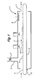
- FIG. 1 there is shown a tunnel freezer which is generally identified by the reference numeral 1.
- the tunnel freezer 1 comprises a belt 2 which carries products 3 to be frozen through the freezing tunnel 4 in the direction of the arrow 'A'.
- tunnel freezer 1 In a modern food freezing factory it is not unusual for the tunnel freezer 1 to be used to freeze a wide range of different food products in the same day. These can vary from whole chicken, to gateau, pre-prepared meals, sauces and desserts and, indeed, we are aware of one factory where runs as short as 30 minutes are commonplace.
- the speed of the belt 3 is varied according to the product.
- Products such as chicken and turkeys take a comparatively long time to freeze whilst thin products such as hamburgers can be frozen relatively quickly.
- the temperature of the gas leaving the freezing tunnel 4 through the exhaust duct 6 should be about -40°C. There are various reasons for this. In particular, if the temperature is allowed to rise above this there is a high risk that the exhaust fan 7 will become iced up and stop working. In addition, the tunnel freezer 1 would become unduly long.
- the belt 3 has an upper run 8 and a lower run 9.
- the belt 3 has an upper run 8 and a lower run 9.
- the spray bar 5 is subject to direct contact with droplets of liquid nitrogen at -196°C.
- the temperature of the belt 3 at the inlet 10 of the tunnel freezer 1 will approximate the desired temperature of the exhaust.
- the speed of the belt 3 is increased so the temperature of the belt 3 at the inlet of tie tunnel freezer 1 falls. This, in turn causes the temperature of the exhaust gas to decrease and reduces the overall efficiency of the freezing process.
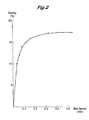
- FIG. 2 there is shown a graph which shows how the savings of liquid nitrogen vary with the velocity of a belt having a weight of 3.28kg per square meter of surface area compared with a conventional belt having a weight of 18.18kg per square meter of surface area.
- This graph refers to steady state running conditions and does not take into account any savings which may be made during initial cooldown.
- the weight per square meter of surface area of the belt would not be expected to be less than 1 km/m 2 because structural reasons.
- FIG. 3 An interesting spin off from the present invention is shown in Figure 3.
- some tunnel freezers are provided with a liquid nitrogen (LIN) tray 14 below the spray bar 5.
- the belt 3 is allowed to sag so that the bottom of the products 3 theoretically touch the liquid nitrogen in the LIN tray 14.
- LIN liquid nitrogen
- the belt 3 may typically comprise a Flat-Flex (Registered trade Mark) XT wire conveyor belt as made by the Wire Belt Company of Sittingbourne, Kent, England.
- a Flat-Flex (Registered trade Mark) XT wire conveyor belt as made by the Wire Belt Company of Sittingbourne, Kent, England.
- the belt 3 will normally be made of stainless steel it could also be made of other metals, for example titanium.
- a belt for a 16m tunnel freezer in accordance with the present invention can be carried by two men.
- tunnel freezers in accordance with the present invention with more support rails underneath the belt 3 and guides above the belt 3. These will, to some extent reduce any savings in liquid nitrogen during initial cooldown.
- belts are run at a continuous speed for the same product regardless of whether the belt is being fed at the rated capacity of the tunnel freezer or between batches.
- Another aspect of the present invention proposes to reduce the belt speed if the temperature of the belt at or around the inlet 10 is lower than desired, which might occur, for example between batches or if the product was being introduced into the tunnel freezer 1 at a rate lower than expected.
- FIG. 4 shows a tunnel freezer 1 which is similar to that shown in Figure 1 and differs therefrom only in that a temperature sensor 12 has been provided which sends a signal to a controller 13 which regulates the speed of a motor 14 which adjusts the speed of the belt 3.
- a sensor couLd be used which measured the coverage of the belt 3 at the inlet 10 of the tunnel freezer 1. This would have the advantage of adjusting the speed of the belt 3 before the temperature around the inlet 10 started dropping although more programming work would be required to correlate the coverage with the speed of the belt.
Landscapes
- Engineering & Computer Science (AREA)
- Mechanical Engineering (AREA)
- Chemical & Material Sciences (AREA)
- Combustion & Propulsion (AREA)
- Physics & Mathematics (AREA)
- Thermal Sciences (AREA)
- General Engineering & Computer Science (AREA)
- Freezing, Cooling And Drying Of Foods (AREA)
- Devices That Are Associated With Refrigeration Equipment (AREA)
- Fish Paste Products (AREA)
Abstract
Description
Claims (8)
- A tunnel freezer having a metal belt for carrying product therethrough, characterised in that the weight of said belt is from 1 kg per square meter of surface area to 6 kg per square meter of surface area.
- A tunnel freezer as claimed in Claim 1, wherein said belt has a weight of from 2 kg per square meter of surface area to 4 kg per square meter of surface area.
- A tunnel freezer as claimed in Claim 2, wherein said belt has a weight of from 2.2 kg per square meter of surface area to 3.1 kg per square meter of surface area
- A tunnel freezer as claimed in Claim 3, wherein said belt has a weight of from 2.6 kg per square meter of surface area to 2.9 kg per square meter of surface area.
- A tunnel freezer as claimed in any preceding Claim, when provided with a tray which, in use, contains liquid cryogen and into which the laden belt sags.
- A method of operating a tunnel freezer having an inlet, an outlet and a belt to convey products to be frozen between said inlet and said outlet, characterized by adjusting the speed of the belt to maintain the temperature of said belt adjacent said inlet substantially constant.
- A tunnel freezer for carrying out a method according to Claim 6, which method is characterised by means to vary the speed of the belt to maintain the temperature of said belt adjacent said inlet substantially constant.
- A tunnel freezer as claimed in Claim 10, wherein said means comprises a temperature sensor located at or adjacent the inlet and arranged to generate a signal indicative of the temperature of said belt adjacent the inlet of said freezing tunnel and a controller arranged to, in use, vary the speed of said belt in response to the signal received from said temperature sensor.
Applications Claiming Priority (2)
| Application Number | Priority Date | Filing Date | Title |
|---|---|---|---|
| GB0123336 | 2001-09-28 | ||
| GB0123336A GB2380247A (en) | 2001-09-28 | 2001-09-28 | Tunnel freezer belt |
Publications (3)
| Publication Number | Publication Date |
|---|---|
| EP1298398A2 true EP1298398A2 (en) | 2003-04-02 |
| EP1298398A3 EP1298398A3 (en) | 2004-10-20 |
| EP1298398B1 EP1298398B1 (en) | 2016-03-23 |
Family
ID=9922869
Family Applications (1)
| Application Number | Title | Priority Date | Filing Date |
|---|---|---|---|
| EP02256798.6A Expired - Lifetime EP1298398B1 (en) | 2001-09-28 | 2002-09-30 | Method and apparatus for freezing products |
Country Status (3)
| Country | Link |
|---|---|
| US (1) | US6725686B2 (en) |
| EP (1) | EP1298398B1 (en) |
| GB (1) | GB2380247A (en) |
Cited By (5)
| Publication number | Priority date | Publication date | Assignee | Title |
|---|---|---|---|---|
| EP1468943A3 (en) * | 2003-04-15 | 2005-01-12 | Integral Technologies, Inc. | Food processing belts and other conveyances manufactured from conductive loaded resin-based materials |
| US7222727B2 (en) | 2001-02-15 | 2007-05-29 | Integral Technologies, Inc. | Low cost food processing belts and other conveyances manufactured from conductive loaded resin-based materials |
| CN103005615A (en) * | 2012-12-18 | 2013-04-03 | 苏州麦克食品机械塑胶有限公司 | Freezing equipment for food processing |
| EP1853116B1 (en) * | 2005-02-15 | 2018-11-07 | MECATHERM, Société Anonyme | Bakery oven comprising a woven mesh belt |
| CN115183513A (en) * | 2022-07-21 | 2022-10-14 | 绍兴老鹰冷冻设备有限公司 | Ultra-low temperature tunnel type instant freezer for cold chain fresh-keeping and quick freezing |
Families Citing this family (9)
| Publication number | Priority date | Publication date | Assignee | Title |
|---|---|---|---|---|
| FR2837563B1 (en) * | 2002-03-21 | 2004-10-22 | Air Liquide | METHOD AND DEVICE FOR CONDUCTING A CRYOGENIC TUNNEL, ASSOCIATED CRYOGENIC TUNNEL |
| DE10346050A1 (en) * | 2003-10-02 | 2005-04-21 | Linde Ag | Process for cutting cheese |
| US7374579B2 (en) * | 2004-08-18 | 2008-05-20 | Cargill, Incorporated | System for extruding, cutting in strands, freezing, and chopping a ground food product and method thereof |
| FR2881923A3 (en) * | 2005-02-15 | 2006-08-18 | Mecatherm | OVEN BOTTOM |
| DE102008019903A1 (en) * | 2008-04-21 | 2009-10-22 | Airinotec Gmbh | Cooling tunnel and method of operating such |
| US20120291456A1 (en) | 2011-05-18 | 2012-11-22 | Rampersad Bryce M | Method and apparatus for contact refrigeration in cryogenic solid belt freezer |
| DK2955466T3 (en) * | 2014-06-13 | 2020-03-16 | John Bean Technologies Ab | TEMPERATURE TREATMENT DEVICE AND PROCEDURE FOR STRENGTHENING LIQUID PORTIONS |
| US20190170424A1 (en) * | 2017-12-01 | 2019-06-06 | Shanghai Ocean University | Jet nozzle structure of impact-type freezer |
| CN115303801A (en) * | 2022-09-06 | 2022-11-08 | 佛山大匠流体科技有限公司 | Be used for refrigerated transmission device of glass |
Family Cites Families (21)
| Publication number | Priority date | Publication date | Assignee | Title |
|---|---|---|---|---|
| US3791162A (en) * | 1972-07-13 | 1974-02-12 | Npi Corp | Double belt freezing machine |
| US3844135A (en) * | 1973-03-22 | 1974-10-29 | Maplecrest Sausage Co Inc | Cooling system for sausages |
| US4062202A (en) * | 1974-09-05 | 1977-12-13 | Cloudy & Britton Inc. | Vibratory weir assembly and method for separating foods being frozen during fluidization in a food freezing tunnel |
| US4128164A (en) * | 1977-11-02 | 1978-12-05 | Formax, Inc. | Constant-tension conveyor drive for thermal processing apparatus |
| GB2023789B (en) * | 1978-06-16 | 1982-12-15 | Boc Ltd | Method and apparatus for cooling or freezing |
| SU881483A1 (en) * | 1980-01-23 | 1981-11-15 | Опытное Конструкторское Бюро Картофелеперерабатывающей Промышленности Научно-Производственного Объединения По Производству Продуктов Из Картофеля | Freezing apparatus conveyer |
| US4333318A (en) * | 1981-05-04 | 1982-06-08 | Lewis Tyree Jr | CO2 Freezer |
| US4403479A (en) * | 1981-09-02 | 1983-09-13 | Ivan Rasovich | Quick freezing system |
| US4852358A (en) * | 1988-07-16 | 1989-08-01 | Union Carbide Corporation | Cryogenic combination tunnel freezer |
| US4858445A (en) * | 1988-09-26 | 1989-08-22 | Ivan Rasovich | Combination cryogenic and mechanical freezing system |
| GB2225629B (en) * | 1988-12-23 | 1992-11-18 | Nissin Gourmet Beef Co Ltd | Continuous quick freezing method for food |
| US4955209A (en) * | 1989-11-01 | 1990-09-11 | Cryo-Chem Inc. | Cryogenic bath freezer with pivoted conveyor belt |
| US5220803A (en) * | 1991-11-07 | 1993-06-22 | Air Products And Chemicals, Inc. | Cryo-mechanical system for reducing dehydration during freezing of foodstuffs |
| FR2686403B1 (en) * | 1992-01-21 | 2001-02-09 | Air Liquide | FREEZING PROCESS AND DEVICE. |
| GB9306301D0 (en) * | 1993-03-26 | 1993-05-19 | Boc Group Plc | Freezing apparatus and method |
| US5520004A (en) * | 1994-06-28 | 1996-05-28 | Jones, Iii; Robert H. | Apparatus and methods for cryogenic treatment of materials |
| US5509277A (en) * | 1994-12-14 | 1996-04-23 | Air Products And Chemicals, Inc. | Combination immersion/impingement tunnel freezer |
| GB9501403D0 (en) * | 1995-01-25 | 1995-03-15 | Boc Group Plc | A food freezing apparatus |
| FR2748315B1 (en) * | 1996-05-06 | 1998-06-05 | Air Liquide | DEVICE FOR ONLINE CRUISING OF PRODUCTS |
| US5860282A (en) * | 1997-07-24 | 1999-01-19 | Winterlab Limited | Process for preparing ice substitutes |
| US6009719A (en) * | 1998-05-06 | 2000-01-04 | York International Corporation | System for thermal treating of food products |
-
2001
- 2001-09-28 GB GB0123336A patent/GB2380247A/en not_active Withdrawn
-
2002
- 2002-09-30 US US10/262,396 patent/US6725686B2/en not_active Expired - Lifetime
- 2002-09-30 EP EP02256798.6A patent/EP1298398B1/en not_active Expired - Lifetime
Cited By (5)
| Publication number | Priority date | Publication date | Assignee | Title |
|---|---|---|---|---|
| US7222727B2 (en) | 2001-02-15 | 2007-05-29 | Integral Technologies, Inc. | Low cost food processing belts and other conveyances manufactured from conductive loaded resin-based materials |
| EP1468943A3 (en) * | 2003-04-15 | 2005-01-12 | Integral Technologies, Inc. | Food processing belts and other conveyances manufactured from conductive loaded resin-based materials |
| EP1853116B1 (en) * | 2005-02-15 | 2018-11-07 | MECATHERM, Société Anonyme | Bakery oven comprising a woven mesh belt |
| CN103005615A (en) * | 2012-12-18 | 2013-04-03 | 苏州麦克食品机械塑胶有限公司 | Freezing equipment for food processing |
| CN115183513A (en) * | 2022-07-21 | 2022-10-14 | 绍兴老鹰冷冻设备有限公司 | Ultra-low temperature tunnel type instant freezer for cold chain fresh-keeping and quick freezing |
Also Published As
| Publication number | Publication date |
|---|---|
| US20030074904A1 (en) | 2003-04-24 |
| US6725686B2 (en) | 2004-04-27 |
| GB0123336D0 (en) | 2001-11-21 |
| EP1298398B1 (en) | 2016-03-23 |
| EP1298398A3 (en) | 2004-10-20 |
| GB2380247A (en) | 2003-04-02 |
Similar Documents
| Publication | Publication Date | Title |
|---|---|---|
| US6725686B2 (en) | Method and apparatus for freezing products | |
| US4528819A (en) | Exhaust control for cryogenic freezer | |
| AU664238B2 (en) | Freezing method and device | |
| US4697508A (en) | Cooling auger | |
| US4745762A (en) | Method and apparatus for cooling or freezing | |
| AU646601B2 (en) | Cryogenic freezer apparatus and method | |
| US6038868A (en) | Freezer apparatus | |
| CN1498332A (en) | Food cooling method and apparatus | |
| EP0667503B1 (en) | Tunnel freezer | |
| US4499740A (en) | Freezer | |
| US5460015A (en) | Freezer with imperforate conveyor belt | |
| GB2225846A (en) | Tunnel freezer | |
| AU2007299311B2 (en) | Device for the rapid freezing of substances | |
| GB2110806A (en) | Method and apparatus for depositing solid carbon dioxide | |
| EP0881888B1 (en) | Precooler device for a food freezing tunnel | |
| WO2007057331A1 (en) | Process and apparatus for filling a container with food articles | |
| EP0583692B1 (en) | Freezer | |
| CN208387867U (en) | Metal detection device for eliminating | |
| CZ268593A3 (en) | Cooling of lumpy or bulk material | |
| JPS6138789B2 (en) | ||
| EP0728995A2 (en) | A food freezing apparatus | |
| US20050241331A1 (en) | Method and device for refrigerating and/or freezing articles | |
| CN107600502A (en) | Meat-patty automated production packaging system | |
| US20060288712A1 (en) | Method for the cryogenic cooling of powders using an early control strategy | |
| CA1045444A (en) | Individual quick-freezing of moist articles using deep fluidized bed and input conditioner |
Legal Events
| Date | Code | Title | Description |
|---|---|---|---|
| PUAI | Public reference made under article 153(3) epc to a published international application that has entered the european phase |
Free format text: ORIGINAL CODE: 0009012 |
|
| AK | Designated contracting states |
Kind code of ref document: A2 Designated state(s): AT BE BG CH CY CZ DE DK EE ES FI FR GB GR IE IT LI LU MC NL PT SE SK TR Designated state(s): AT BE BG CH CY CZ DE DK EE ES FI FR GB GR IE IT LI LU MC NL PT SE SK TR |
|
| AX | Request for extension of the european patent |
Extension state: AL LT LV MK RO SI |
|
| RIC1 | Information provided on ipc code assigned before grant |
Ipc: 7F 25D 3/11 B Ipc: 7F 25D 25/04 A Ipc: 7B 65G 15/48 B |
|
| PUAL | Search report despatched |
Free format text: ORIGINAL CODE: 0009013 |
|
| AK | Designated contracting states |
Kind code of ref document: A3 Designated state(s): AT BE BG CH CY CZ DE DK EE ES FI FR GB GR IE IT LI LU MC NL PT SE SK TR |
|
| AX | Request for extension of the european patent |
Extension state: AL LT LV MK RO SI |
|
| 17P | Request for examination filed |
Effective date: 20041108 |
|
| AKX | Designation fees paid |
Designated state(s): AT BE BG CH CY CZ DE DK EE ES FI FR GB GR IE IT LI LU MC NL PT SE SK TR |
|
| 17Q | First examination report despatched |
Effective date: 20070105 |
|
| GRAP | Despatch of communication of intention to grant a patent |
Free format text: ORIGINAL CODE: EPIDOSNIGR1 |
|
| INTG | Intention to grant announced |
Effective date: 20150507 |
|
| GRAJ | Information related to disapproval of communication of intention to grant by the applicant or resumption of examination proceedings by the epo deleted |
Free format text: ORIGINAL CODE: EPIDOSDIGR1 |
|
| GRAP | Despatch of communication of intention to grant a patent |
Free format text: ORIGINAL CODE: EPIDOSNIGR1 |
|
| INTG | Intention to grant announced |
Effective date: 20150922 |
|
| GRAS | Grant fee paid |
Free format text: ORIGINAL CODE: EPIDOSNIGR3 |
|
| GRAA | (expected) grant |
Free format text: ORIGINAL CODE: 0009210 |
|
| AK | Designated contracting states |
Kind code of ref document: B1 Designated state(s): AT BE BG CH CY CZ DE DK EE ES FI FR GB GR IE IT LI LU MC NL PT SE SK TR |
|
| REG | Reference to a national code |
Ref country code: GB Ref legal event code: FG4D |
|
| REG | Reference to a national code |
Ref country code: CH Ref legal event code: EP |
|
| REG | Reference to a national code |
Ref country code: AT Ref legal event code: REF Ref document number: 783565 Country of ref document: AT Kind code of ref document: T Effective date: 20160415 |
|
| REG | Reference to a national code |
Ref country code: IE Ref legal event code: FG4D |
|
| REG | Reference to a national code |
Ref country code: DE Ref legal event code: R096 Ref document number: 60247885 Country of ref document: DE |
|
| REG | Reference to a national code |
Ref country code: NL Ref legal event code: MP Effective date: 20160323 |
|
| PG25 | Lapsed in a contracting state [announced via postgrant information from national office to epo] |
Ref country code: GR Free format text: LAPSE BECAUSE OF FAILURE TO SUBMIT A TRANSLATION OF THE DESCRIPTION OR TO PAY THE FEE WITHIN THE PRESCRIBED TIME-LIMIT Effective date: 20160624 Ref country code: FI Free format text: LAPSE BECAUSE OF FAILURE TO SUBMIT A TRANSLATION OF THE DESCRIPTION OR TO PAY THE FEE WITHIN THE PRESCRIBED TIME-LIMIT Effective date: 20160323 |
|
| REG | Reference to a national code |
Ref country code: AT Ref legal event code: MK05 Ref document number: 783565 Country of ref document: AT Kind code of ref document: T Effective date: 20160323 |
|
| PG25 | Lapsed in a contracting state [announced via postgrant information from national office to epo] |
Ref country code: SE Free format text: LAPSE BECAUSE OF FAILURE TO SUBMIT A TRANSLATION OF THE DESCRIPTION OR TO PAY THE FEE WITHIN THE PRESCRIBED TIME-LIMIT Effective date: 20160323 Ref country code: NL Free format text: LAPSE BECAUSE OF FAILURE TO SUBMIT A TRANSLATION OF THE DESCRIPTION OR TO PAY THE FEE WITHIN THE PRESCRIBED TIME-LIMIT Effective date: 20160323 |
|
| PG25 | Lapsed in a contracting state [announced via postgrant information from national office to epo] |
Ref country code: EE Free format text: LAPSE BECAUSE OF FAILURE TO SUBMIT A TRANSLATION OF THE DESCRIPTION OR TO PAY THE FEE WITHIN THE PRESCRIBED TIME-LIMIT Effective date: 20160323 |
|
| PG25 | Lapsed in a contracting state [announced via postgrant information from national office to epo] |
Ref country code: AT Free format text: LAPSE BECAUSE OF FAILURE TO SUBMIT A TRANSLATION OF THE DESCRIPTION OR TO PAY THE FEE WITHIN THE PRESCRIBED TIME-LIMIT Effective date: 20160323 Ref country code: CZ Free format text: LAPSE BECAUSE OF FAILURE TO SUBMIT A TRANSLATION OF THE DESCRIPTION OR TO PAY THE FEE WITHIN THE PRESCRIBED TIME-LIMIT Effective date: 20160323 Ref country code: SK Free format text: LAPSE BECAUSE OF FAILURE TO SUBMIT A TRANSLATION OF THE DESCRIPTION OR TO PAY THE FEE WITHIN THE PRESCRIBED TIME-LIMIT Effective date: 20160323 Ref country code: PT Free format text: LAPSE BECAUSE OF FAILURE TO SUBMIT A TRANSLATION OF THE DESCRIPTION OR TO PAY THE FEE WITHIN THE PRESCRIBED TIME-LIMIT Effective date: 20160725 Ref country code: ES Free format text: LAPSE BECAUSE OF FAILURE TO SUBMIT A TRANSLATION OF THE DESCRIPTION OR TO PAY THE FEE WITHIN THE PRESCRIBED TIME-LIMIT Effective date: 20160323 |
|
| PG25 | Lapsed in a contracting state [announced via postgrant information from national office to epo] |
Ref country code: BE Free format text: LAPSE BECAUSE OF FAILURE TO SUBMIT A TRANSLATION OF THE DESCRIPTION OR TO PAY THE FEE WITHIN THE PRESCRIBED TIME-LIMIT Effective date: 20160323 Ref country code: IT Free format text: LAPSE BECAUSE OF FAILURE TO SUBMIT A TRANSLATION OF THE DESCRIPTION OR TO PAY THE FEE WITHIN THE PRESCRIBED TIME-LIMIT Effective date: 20160323 |
|
| REG | Reference to a national code |
Ref country code: DE Ref legal event code: R097 Ref document number: 60247885 Country of ref document: DE |
|
| PLBE | No opposition filed within time limit |
Free format text: ORIGINAL CODE: 0009261 |
|
| STAA | Information on the status of an ep patent application or granted ep patent |
Free format text: STATUS: NO OPPOSITION FILED WITHIN TIME LIMIT |
|
| PG25 | Lapsed in a contracting state [announced via postgrant information from national office to epo] |
Ref country code: DK Free format text: LAPSE BECAUSE OF FAILURE TO SUBMIT A TRANSLATION OF THE DESCRIPTION OR TO PAY THE FEE WITHIN THE PRESCRIBED TIME-LIMIT Effective date: 20160323 |
|
| PG25 | Lapsed in a contracting state [announced via postgrant information from national office to epo] |
Ref country code: BG Free format text: LAPSE BECAUSE OF FAILURE TO SUBMIT A TRANSLATION OF THE DESCRIPTION OR TO PAY THE FEE WITHIN THE PRESCRIBED TIME-LIMIT Effective date: 20160623 |
|
| 26N | No opposition filed |
Effective date: 20170102 |
|
| PG25 | Lapsed in a contracting state [announced via postgrant information from national office to epo] |
Ref country code: MC Free format text: LAPSE BECAUSE OF FAILURE TO SUBMIT A TRANSLATION OF THE DESCRIPTION OR TO PAY THE FEE WITHIN THE PRESCRIBED TIME-LIMIT Effective date: 20160323 |
|
| REG | Reference to a national code |
Ref country code: CH Ref legal event code: PL |
|
| GBPC | Gb: european patent ceased through non-payment of renewal fee |
Effective date: 20160930 |
|
| REG | Reference to a national code |
Ref country code: IE Ref legal event code: MM4A |
|
| REG | Reference to a national code |
Ref country code: FR Ref legal event code: ST Effective date: 20170531 |
|
| PG25 | Lapsed in a contracting state [announced via postgrant information from national office to epo] |
Ref country code: IE Free format text: LAPSE BECAUSE OF NON-PAYMENT OF DUE FEES Effective date: 20160930 Ref country code: FR Free format text: LAPSE BECAUSE OF NON-PAYMENT OF DUE FEES Effective date: 20160930 Ref country code: CH Free format text: LAPSE BECAUSE OF NON-PAYMENT OF DUE FEES Effective date: 20160930 Ref country code: GB Free format text: LAPSE BECAUSE OF NON-PAYMENT OF DUE FEES Effective date: 20160930 Ref country code: LI Free format text: LAPSE BECAUSE OF NON-PAYMENT OF DUE FEES Effective date: 20160930 |
|
| PG25 | Lapsed in a contracting state [announced via postgrant information from national office to epo] |
Ref country code: LU Free format text: LAPSE BECAUSE OF NON-PAYMENT OF DUE FEES Effective date: 20160930 |
|
| PG25 | Lapsed in a contracting state [announced via postgrant information from national office to epo] |
Ref country code: CY Free format text: LAPSE BECAUSE OF FAILURE TO SUBMIT A TRANSLATION OF THE DESCRIPTION OR TO PAY THE FEE WITHIN THE PRESCRIBED TIME-LIMIT Effective date: 20160323 |
|
| PG25 | Lapsed in a contracting state [announced via postgrant information from national office to epo] |
Ref country code: TR Free format text: LAPSE BECAUSE OF FAILURE TO SUBMIT A TRANSLATION OF THE DESCRIPTION OR TO PAY THE FEE WITHIN THE PRESCRIBED TIME-LIMIT Effective date: 20160323 |
|
| PGFP | Annual fee paid to national office [announced via postgrant information from national office to epo] |
Ref country code: DE Payment date: 20210818 Year of fee payment: 20 |
|
| REG | Reference to a national code |
Ref country code: DE Ref legal event code: R071 Ref document number: 60247885 Country of ref document: DE |