EP1298350A2 - Torque converter - Google Patents
Torque converter Download PDFInfo
- Publication number
- EP1298350A2 EP1298350A2 EP02020666A EP02020666A EP1298350A2 EP 1298350 A2 EP1298350 A2 EP 1298350A2 EP 02020666 A EP02020666 A EP 02020666A EP 02020666 A EP02020666 A EP 02020666A EP 1298350 A2 EP1298350 A2 EP 1298350A2
- Authority
- EP
- European Patent Office
- Prior art keywords
- torque
- stator
- converter
- ratio
- torque converter
- Prior art date
- Legal status (The legal status is an assumption and is not a legal conclusion. Google has not performed a legal analysis and makes no representation as to the accuracy of the status listed.)
- Granted
Links
- 230000004323 axial length Effects 0.000 claims abstract description 33
- 230000005540 biological transmission Effects 0.000 claims abstract description 20
- 239000012530 fluid Substances 0.000 claims abstract description 10
- 230000007423 decrease Effects 0.000 claims description 10
- 230000008859 change Effects 0.000 claims description 8
- 239000000446 fuel Substances 0.000 abstract description 9
- 239000003921 oil Substances 0.000 description 26
- 239000010687 lubricating oil Substances 0.000 description 23
- 230000002093 peripheral effect Effects 0.000 description 10
- 230000001965 increasing effect Effects 0.000 description 8
- 238000003780 insertion Methods 0.000 description 3
- 230000037431 insertion Effects 0.000 description 3
- 238000013459 approach Methods 0.000 description 2
- 238000002485 combustion reaction Methods 0.000 description 2
- 230000008878 coupling Effects 0.000 description 2
- 238000010168 coupling process Methods 0.000 description 2
- 238000005859 coupling reaction Methods 0.000 description 2
- 238000010586 diagram Methods 0.000 description 2
- 230000009471 action Effects 0.000 description 1
- 230000001419 dependent effect Effects 0.000 description 1
- 238000005516 engineering process Methods 0.000 description 1
- 230000002708 enhancing effect Effects 0.000 description 1
- 238000004519 manufacturing process Methods 0.000 description 1
- 239000002184 metal Substances 0.000 description 1
- 238000012986 modification Methods 0.000 description 1
- 230000004048 modification Effects 0.000 description 1
- 230000009467 reduction Effects 0.000 description 1
- 230000004044 response Effects 0.000 description 1
- 238000004904 shortening Methods 0.000 description 1
- 238000003466 welding Methods 0.000 description 1
Images



Classifications
-
- F—MECHANICAL ENGINEERING; LIGHTING; HEATING; WEAPONS; BLASTING
- F16—ENGINEERING ELEMENTS AND UNITS; GENERAL MEASURES FOR PRODUCING AND MAINTAINING EFFECTIVE FUNCTIONING OF MACHINES OR INSTALLATIONS; THERMAL INSULATION IN GENERAL
- F16H—GEARING
- F16H41/00—Rotary fluid gearing of the hydrokinetic type
- F16H41/24—Details
- F16H41/26—Shape of runner blades or channels with respect to function
-
- F—MECHANICAL ENGINEERING; LIGHTING; HEATING; WEAPONS; BLASTING
- F16—ENGINEERING ELEMENTS AND UNITS; GENERAL MEASURES FOR PRODUCING AND MAINTAINING EFFECTIVE FUNCTIONING OF MACHINES OR INSTALLATIONS; THERMAL INSULATION IN GENERAL
- F16H—GEARING
- F16H45/00—Combinations of fluid gearings for conveying rotary motion with couplings or clutches
- F16H45/02—Combinations of fluid gearings for conveying rotary motion with couplings or clutches with mechanical clutches for bridging a fluid gearing of the hydrokinetic type
- F16H2045/0273—Combinations of fluid gearings for conveying rotary motion with couplings or clutches with mechanical clutches for bridging a fluid gearing of the hydrokinetic type characterised by the type of the friction surface of the lock-up clutch
- F16H2045/0294—Single disk type lock-up clutch, i.e. using a single disc engaged between friction members
-
- F—MECHANICAL ENGINEERING; LIGHTING; HEATING; WEAPONS; BLASTING
- F16—ENGINEERING ELEMENTS AND UNITS; GENERAL MEASURES FOR PRODUCING AND MAINTAINING EFFECTIVE FUNCTIONING OF MACHINES OR INSTALLATIONS; THERMAL INSULATION IN GENERAL
- F16H—GEARING
- F16H45/00—Combinations of fluid gearings for conveying rotary motion with couplings or clutches
- F16H45/02—Combinations of fluid gearings for conveying rotary motion with couplings or clutches with mechanical clutches for bridging a fluid gearing of the hydrokinetic type
Definitions
- the present invention relates to a torque converter into which a driving power is transferred from a driving power source such as an engine, and specifically to technologies for enhancing operating characteristics of a torque converter such as reduced torque capacity coefficient and increased torque ratio at stall.
- Torque converters generally utilize three major rotating elements, namely a pump impeller (a driving member), a turbine runner (a driven member), and a stator located at the inner portion of the converter between the pump impeller and the turbine runner.
- the three major rotating elements cooperate with each other to provide oil circulation passage within the converter unit.
- the pump impeller is driven by input torque from the power source.
- the working fluid or working oil is pumped from the impeller blades across to the turbine blades, then back to the pump impeller via the stator for torque transmission from the impeller to the turbine.
- an axial length of the stator is generally set at a value as long as possible.
- the longer axial length of the stator has a merit that it is possible to maintain (i) the outlet slip angle at stall wherein a speed ratio e of turbine runner speed to pump impeller speed is substantially "0" (e ⁇ 0) and (ii) the outlet slip angle obtained when the turbine runner speed approaches the pump impeller speed (for example, e ⁇ 0.8) almost at the same.
- the longer axial length of the stator has the following drawbacks. That is, the longer the axial length of the stator, the wider the stator blade area.
- the wider stator blade area results in an increase in frictional loss (energy loss) within the torque converter. This lowers a power transmission efficiency as well as a torque ratio, thus lowering the startability of the vehicle and increasing fuel consumption in particular at idle. Additionally, there is an increased tendency for a radius-of-curvature R of a leading edge of the stator blade to become greater due to the axial length of the stator. Such a greater radius-of-curvature R of the stator-blade leading edge facilitates smooth working oil flow along the stator blade surface when the turbine is in stall. A flow rate of working oil broken away the stator blade surface tends to reduce. As a whole, the flow rate of working oil tends to increase. This leads to the problem of a high torque capacity coefficient at stall, that is, increased fuel consumption at idle.
- a torque converter comprises a converter cover to which a driving power is transmitted from a driving power source, a pump impeller formed integral with the converter cover, a turbine runner to which the driving power is transmitted through a working fluid from the pump impeller, a stator disposed between the pump impeller and the turbine runner and supported on a transmission case via a one-way clutch and having stator blades, and a ratio W/D of a stator-blade axial length W of the stator to a torque-converter nominal diameter D of the torque converter being set to satisfy a predetermined inequality 0.030 ⁇ W/D ⁇ 0.052.
- a torque converter comprises a converter cover to which a driving power is transmitted from a driving power source, a pump impeller formed integral with the converter cover, a turbine runner to which the driving power is transmitted through a working fluid from the pump impeller, a stator disposed between the pump impeller and the turbine runner and supported on a transmission case via a one-way clutch and having stator blades , and a ratio W/D of a stator-blade axial length W of the stator to a torque-converter nominal diameter D of the torque converter being set to satisfy a predetermined necessary condition that a decrease rate of a stall torque ratio with respect to a peak torque ratio at stall is less than or equal to 1%.
- the torque-converter nominal diameter D means an outside diameter of the pump impeller and the turbine runner. It is preferable that the predetermined necessary condition is represented by an inequality A ⁇ W/D ⁇ B, where A is a lower limit of the ratio W/D, obtained when a rate of change in the stall torque ratio reduces to 1% in accordance with a decrease in the ratio W/D from a peak point corresponding to the peak torque ratio, whereas B is an upper limit of the ratio W/D, obtained when the rate of change in the stall torque ratio reduces to 1% in accordance with an increase in the ratio W/D from the peak point corresponding to the peak torque ratio.
- the lower limit A may be set to 0.030 and the upper limit B may be set to 0.052, and the predetermined necessary condition may be represented by the inequality 0.030 ⁇ W/D ⁇ 0.052.
- Torque converter 1 includes a converter cover 6 (a two-piece stamped metal shell) that is constructed by a front cover 2 and a rear cover 5 welded together. Front cover 2 is fixedly connected to a driving power source such as an internal combustion engine. Rear cover 5 is rotatably supported by an oil pump case 4 that is attached to the front-end face of a transmission case 3M of an automatic transmission 3.
- reference sign 3C denotes a converter housing.
- Front cover 2 is comprised of a forward disk-shaped portion 2a and a peripheral cylindrical portion 2b axially extending from the outer periphery of forward disk-shaped portion 2a.
- forward disk-shaped portion 2a is formed with a central backwardly recessed portion 2c.
- An axially forward extending cylindrical hollow shaft portion 2d is formed at the center position of central backwardly recessed portion 2c.
- Circumferentially equidistant spaced, four weld nuts 7 are fixed onto the perimeter of forward disk-shaped portion 2a so as to connect the converter cover to the driving power source (the engine).
- converter cover 6 is fixedly connected to an engine crankshaft 8 via a first drive plate 9 serving as a coupling member between the converter cover and engine crankshaft.
- First drive plate 9 is formed at its center with an insertion hole 9a into which an axially-protruding portion 8a of crankshaft 8 is fitted. Under a condition wherein axially-protruding portion 8a and insertion hole 9a are fitted to each other, the peripheral portion of first drive plate 9 close to insertion hole 9a is bolted to the rear end of crankshaft 8.
- First drive plate 9 is also formed with four mounting bolt holes 9b that are opposite to the respective weld nuts 7.
- First drive plate 9 is integrally connected to front cover 2 of converter cover 6 by securely screwing bolts 9c into the respective weld nuts 7.
- rear cover 5 is comprised of an inner member 5c having a L-shaped cross section and a torus-shaped outer member 5d.
- Inner and outer members 5c and 5d are welded together.
- Inner member 5c is constructed by an axially-extending cylindrical-hollow portion 5a and a radially-extending flanged portion 5b.
- Cylindrical-hollow portion 5a is rotatably supported by oil pump case 4.
- Flanged portion 5b is formed integral with cylindrical-hollow portion 5a in such a manner as to radially extend from the front end of cylindrical-hollow portion 5a.
- the inner periphery of torus-shaped outer member 5d is welded to the outer periphery of flanged portion 5b of L-shaped inner member 5c, whereas the outer periphery of torus-shaped outer member 5d is fitted to the inner peripheral wall surface of peripheral cylindrical portion 2b of front cover 2 and welded to the front cover by way of welding.
- Cylindrical-hollow portion 5a of L-shaped inner member 5c is rotatably supported on oil pump case 4 through a bushing 4a.
- the rear end portion of cylindrical hollow portion 5a of inner member 5c is connected to the inner periphery of an oil pump 4b that is accommodated in oil pump case 4, by way of spline connection.
- a plurality of impeller blades of a pump impeller 11 are attached to the inner peripheral wall surface of outer member 5d of rear cover 5.
- a plurality of turbine blades of a turbine runner 12 are provided in converter cover 6 so that the turbine blades 17 are opposite to the respective impeller blades of pump impeller 11.
- a stator 15 is located at the inner portion of torque converter 1 and disposed between pump impeller 11 and turbine runner 12.
- Stator 15 serves as a reactor that redirects working oil flow from turbine runner 12 to boost pump-impeller action and multiplies engine torque.
- Turbine runner 12 is comprised of a turbine shell 16, turbine blades 17, and a turbine hub 18.
- Turbine blades 17 are attached to the inner peripheral wall surface of turbine shell 16.
- Turbine hub 18 supports the inner peripheral portion of turbine shell 16.
- Turbine hub 18 is splined to a rotating shaft 19 (or an automatic transmission input shaft) that is rotatably supported by transmission case 3M.
- Turbine shell 16 is comprised of a main torus-shaped portion 16a formed integral with turbine blades 17, a substantially cylindrical portion 16b having a slight axial length, and a substantially annular innermost mounting portion 16c.
- Cylindrical portion 16b is integrally formed with main torus-shaped portion 16a in a manner so as to slightly extend forwards from the inner periphery of main torus-shaped portion 16a in the axial direction. As viewed from the cross section of Fig.
- annular innermost mounting portion 16c is integrally formed with cylindrical portion 16b in a manner so as to be bent radially inwards from the forward end of cylindrical portion 16b.
- Stator 15 is installed on a cylindrical hollow support portion 13a through a one-way clutch 14.
- Cylindrical hollow support portion 13a is formed integral with an oil pump cover 13 and constructs part of transmission case 3M.
- Oil pump cover 13 is fitted and bolted to the rear face of oil pump case 4 to hermetically cover the rear end of oil pump case 4.
- Stator 15 is comprised of a stator hub 15a and a plurality of stator blades 15b.
- Stator hub 15a is fixedly connected to an outerrace 14c of one-way clutch 14.
- Stator blades 15b are attached onto the outer periphery of stator hub 15a.
- a ratio W/D of a stator-blade axial length W to a nominal diameter D of torque converter 1 (that is, an outside diameter of pump impeller 11 and turbine runner 12) is set to satisfy the following inequality (1). 0.030 ⁇ W/D ⁇ 0.052
- the greater the ratio W/D is set, the longer the stator-blade axial length W can become.
- stator-blade axial length W must be optimally set or specified with regard to the nominal diameter D of torque converter 1 for the following reason. Breakaway burble and energy loss occurring within the torque converter are greatly affected by a flow velocity of working oil (working fluid) flowing through turbine blades 17.
- the flow velocity of working oil flow is mainly determined depending on the nominal diameter D of torque converter 1. That is, nominal diameter D of torque converter 1 can be regarded as a control parameter closely related to the breakaway burble and energy loss occurring within the converter.
- the solid line indicates the characteristics (the torque ratio, torque capacity coefficient ⁇ , and converter efficiency) of the torque converter of the embodiment whose ratio W/D is set at 0.052 included in the predetermined range defined by 0.030 ⁇ W/D ⁇ 0.052.
- the broken line indicates the characteristics (the torque ratio, torque capacity coefficient ⁇ , and converter efficiency) of the torque converter of the embodiment whose ratio W/D is set at 0.040 included in the predetermined range defined by 0.030 ⁇ W/D ⁇ 0.052 and capable of providing the peak torque ratio.
- the torque capacity coefficient ⁇ at stall becomes comparatively greater.
- an aerofoil section of turbine blade 17 or stator blade 15b having a relatively long axial length W (see Fig. 4A) and an aerofoil section of turbine blade 17 or stator blade 15b having a relatively short axial length W (see Fig. 4B) are usually designed and dimensioned as similar geometrical figures.
- the ratio W/D of stator-blade axial length W to torque-converter nominal diameter D is set to satisfy the inequality 0.030 ⁇ W/D ⁇ 0.052.
- input rotational speed Ni of torque converter 1 is set or adjusted to a substantially constant speed (a designated low speed) with the engine at an idle rpm.
- the relatively lower setting of torque capacity coefficient ⁇ at and near stall contributes to an effective decrease in torque-converter input torque Ti.
- the effective decrease in torque-converter input torque Ti at and near stall in other words, during idling, contributes to a reduction in engine load, thus improving fuel economy (or reducing fuel consumption) during idling.
- a lock-up clutch 22 is disposed between front cover 2 and turbine runner 12 such that the torque converter (pump and turbine elements) is automatically locked up in predetermined gear ranges to eliminate internal slippage (energy loss) and improve fuel economy.
- Lock-up clutch 22 includes a lock-up piston 23.
- Lock-up piston 23 is comprised of an inside cylindrical portion 23a and an outside cylindrical portion 23b. Inside cylindrical portion 23a of lock-up piston 23 is fitted onto (or splined to) the outer peripheral surface of the cylindrical portion of turbine hub 18, so that lock-up piston 23 is axially slidable relative to turbine hub 18 and that lock-up piston 23 rotates together with turbine hub 18.
- Reference sign 27 denotes a side plate that is integrally connected to second drive plate 26. Outside ends of second drive plate 26 and side plate 27 are slidably fitted into and engaged with respective circumferentially-equidistant spaced engaging grooves 23c of outside cylindrical portion 23b of lock-up piston 23.
- the torque converter of the embodiment operates as follows. In a particular state wherein the vehicle is stopped and the engine is idling at an idle rpm, a lubricating oil, having a slightly higher pressure level than a pressure level of lubricating oil filling up a pump and turbine accommodating chamber 31, is supplied into a lubricating oil passage 30 bored in rotating shaft 19. Pump and turbine accommodating chamber 31 accommodates therein pump impeller 11 and turbine runner 12. Fluid pressure in the lubricating oil (or working oil) in pump and turbine accommodating chamber 31 is applied to the rear face of lock-up piston 23.
- lock-up facing 23d is held spaced apart from flat surface 23e of front cover 2 (see a slight space defined between the lock-up facing and the front-cover flat surface in Fig. 1), owing to the relatively higher lubricating oil pressure in lubricating oil chamber 32.
- This is called "lock-up clutch disengagement state".
- first drive plate 9 the coupling member between the converter cover and engine crankshaft
- weld nuts 7 into front cover 2.
- Driving torque is then transmitted through rear cover 5 formed integral with front cover 2 into pump impeller 11.
- the working oil (lubricating oil) in pump and turbine accommodating chamber 31 is pumped from the pump impeller blades across to turbine blades 17, then back to pump impeller 11 via stator blades 15b of stator 15 to provide oil circulation passage and to ensure torque transmission from the pump impeller to the turbine runner.
- the ratio W/D of stator-blade axial length W to torque-converter nominal diameter D is set to satisfy the inequality 0.030 ⁇ W/D ⁇ 0.052.
- rotating shaft 19 When switching from the vehicle's stopped state to the vehicle's starting state, rotating shaft 19 is shifted from its stopped state to its rotatable state.
- turbine runner 12 shifts from the stopped state to the rotating state and begins to rotate by way of the kinetic energy of lubricating oil obtained owing to rotation of pump impeller 11.
- the torque converter of the embodiment can maintain the torque ratio at and near stall at a relatively higher level. This effectively enhances the vehicle's startability.
- the torque converter is exemplified in a so-called lock-up torque converter with lock-up clutch 22.
- the lock-up torque converter is conventional and forms no part of the present invention.
- lock-up clutch 22 may be omitted.
- Torque converter 1 of the embodiment is driven by a crankshaft of an internal combustion engine serving as a driving power source.
- the other driving power source such as an electric motor or an electric motor/generator for use in an electric vehicle or a hybrid vehicle, may be used instead of the engine.
Landscapes
- Engineering & Computer Science (AREA)
- General Engineering & Computer Science (AREA)
- Mechanical Engineering (AREA)
- Control Of Fluid Gearings (AREA)
Abstract
Description
- The present invention relates to a torque converter into which a driving power is transferred from a driving power source such as an engine, and specifically to technologies for enhancing operating characteristics of a torque converter such as reduced torque capacity coefficient and increased torque ratio at stall.
- Torque converters generally utilize three major rotating elements, namely a pump impeller (a driving member), a turbine runner (a driven member), and a stator located at the inner portion of the converter between the pump impeller and the turbine runner. The three major rotating elements cooperate with each other to provide oil circulation passage within the converter unit. Concretely, during operation of the driving power source (engine), the pump impeller is driven by input torque from the power source. When the engine is running and thus the pump impeller is rotating, the working fluid or working oil is pumped from the impeller blades across to the turbine blades, then back to the pump impeller via the stator for torque transmission from the impeller to the turbine.
- To provide a desirable design outlet slip angle of working oil flow from stator blades, an axial length of the stator is generally set at a value as long as possible. The longer axial length of the stator has a merit that it is possible to maintain (i) the outlet slip angle at stall wherein a speed ratio e of turbine runner speed to pump impeller speed is substantially "0" (e ≒ 0) and (ii) the outlet slip angle obtained when the turbine runner speed approaches the pump impeller speed (for example, e ≒ 0.8) almost at the same. However, the longer axial length of the stator has the following drawbacks. That is, the longer the axial length of the stator, the wider the stator blade area. The wider stator blade area results in an increase in frictional loss (energy loss) within the torque converter. This lowers a power transmission efficiency as well as a torque ratio, thus lowering the startability of the vehicle and increasing fuel consumption in particular at idle. Additionally, there is an increased tendency for a radius-of-curvature R of a leading edge of the stator blade to become greater due to the axial length of the stator. Such a greater radius-of-curvature R of the stator-blade leading edge facilitates smooth working oil flow along the stator blade surface when the turbine is in stall. A flow rate of working oil broken away the stator blade surface tends to reduce. As a whole, the flow rate of working oil tends to increase. This leads to the problem of a high torque capacity coefficient at stall, that is, increased fuel consumption at idle.
- Accordingly, it is an object of the invention to provide a torque converter, capable of suppressing a fuel consumption rate at idle from increasing, while ensuring a high startability of an automotive vehicle.
- In order to accomplish the aforementioned and other objects of the present invention, a torque converter comprises a converter cover to which a driving power is transmitted from a driving power source, a pump impeller formed integral with the converter cover, a turbine runner to which the driving power is transmitted through a working fluid from the pump impeller, a stator disposed between the pump impeller and the turbine runner and supported on a transmission case via a one-way clutch and having stator blades, and a ratio W/D of a stator-blade axial length W of the stator to a torque-converter nominal diameter D of the torque converter being set to satisfy a predetermined inequality 0.030≤W/D≤0.052.
- According to another aspect of the invention, a torque converter comprises a converter cover to which a driving power is transmitted from a driving power source, a pump impeller formed integral with the converter cover, a turbine runner to which the driving power is transmitted through a working fluid from the pump impeller, a stator disposed between the pump impeller and the turbine runner and supported on a transmission case via a one-way clutch and having stator blades , and a ratio W/D of a stator-blade axial length W of the stator to a torque-converter nominal diameter D of the torque converter being set to satisfy a predetermined necessary condition that a decrease rate of a stall torque ratio with respect to a peak torque ratio at stall is less than or equal to 1%. The torque-converter nominal diameter D means an outside diameter of the pump impeller and the turbine runner. It is preferable that the predetermined necessary condition is represented by an inequality A≤W/D≤B, where A is a lower limit of the ratio W/D, obtained when a rate of change in the stall torque ratio reduces to 1% in accordance with a decrease in the ratio W/D from a peak point corresponding to the peak torque ratio, whereas B is an upper limit of the ratio W/D, obtained when the rate of change in the stall torque ratio reduces to 1% in accordance with an increase in the ratio W/D from the peak point corresponding to the peak torque ratio. More preferably, the lower limit A may be set to 0.030 and the upper limit B may be set to 0.052, and the predetermined necessary condition may be represented by the inequality 0.030≤W/D≤0.052. Additionally, within a set range defined by the inequality 0.030≤W/D≤0.052, an aerofoil section of the stator blade of the torque converter may be gradually down-sized as a similar geometrical figure from an aerofoil section of the stator blade of the torque converter having a stator-blade axial length corresponding to the ratio W/D = 0.030 to an aerofoil section of the stator blade of the torque converter having a stator-blade axial length corresponding to the ratio W/D = 0.052.
- The other objects and features of this invention will become understood from the following description with reference to the accompanying drawings.
-
- Fig. 1 is a longitudinal cross-sectional view illustrating a torque converter of the embodiment.
- Fig. 2 is a characteristic curve showing the relationship between a ratio W/D of a stator-blade axial length W to a nominal diameter D of the torque converter of Fig. 1 and a rate-of-change in a stall torque ratio.
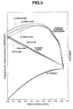
- Fig. 3 shows characteristic curves explaining the relationship among a torque capacity coefficient τ, a torque ratio, a speed ratio e (=Vt/Vp) and a converter efficiency, at three different ratios W/D, namely W/D=0.040, W/D=0.052, and W/D=0.066.
- Figs. 4A, 4B, and 4C are explanatory views showing how the torque capacity coefficient τ is affected by the stator-blade axial length W or the radius-of-curvature R of the stator-blade leading edge.
-
- Referring now to the drawings, particularly to Fig. 1, a
torque converter 1 of the embodiment is exemplified in a lock-up clutch equipped torque converter.Torque converter 1 includes a converter cover 6 (a two-piece stamped metal shell) that is constructed by a front cover 2 and arear cover 5 welded together. Front cover 2 is fixedly connected to a driving power source such as an internal combustion engine.Rear cover 5 is rotatably supported by anoil pump case 4 that is attached to the front-end face of atransmission case 3M of anautomatic transmission 3. In Fig. 1,reference sign 3C denotes a converter housing. Front cover 2 is comprised of a forward disk-shaped portion 2a and a peripheral cylindrical portion 2b axially extending from the outer periphery of forward disk-shaped portion 2a. As clearly seen from the cross section of Fig. 1, forward disk-shaped portion 2a is formed with a central backwardly recessedportion 2c. An axially forward extending cylindricalhollow shaft portion 2d is formed at the center position of central backwardly recessedportion 2c. Circumferentially equidistant spaced, fourweld nuts 7 are fixed onto the perimeter of forward disk-shaped portion 2a so as to connect the converter cover to the driving power source (the engine). In more detail, as can be appreciated from the two-dotted line in the cross section of Fig. 1, converter cover 6 is fixedly connected to anengine crankshaft 8 via afirst drive plate 9 serving as a coupling member between the converter cover and engine crankshaft.First drive plate 9 is formed at its center with aninsertion hole 9a into which an axially-protrudingportion 8a ofcrankshaft 8 is fitted. Under a condition wherein axially-protrudingportion 8a andinsertion hole 9a are fitted to each other, the peripheral portion offirst drive plate 9 close toinsertion hole 9a is bolted to the rear end ofcrankshaft 8.First drive plate 9 is also formed with fourmounting bolt holes 9b that are opposite to therespective weld nuts 7.First drive plate 9 is integrally connected to front cover 2 of converter cover 6 by securely screwingbolts 9c into therespective weld nuts 7. On the other hand,rear cover 5 is comprised of aninner member 5c having a L-shaped cross section and a torus-shapedouter member 5d. Inner andouter members Inner member 5c is constructed by an axially-extending cylindrical-hollow portion 5a and a radially-extendingflanged portion 5b. Cylindrical-hollow portion 5a is rotatably supported byoil pump case 4. Flangedportion 5b is formed integral with cylindrical-hollow portion 5a in such a manner as to radially extend from the front end of cylindrical-hollow portion 5a. The inner periphery of torus-shapedouter member 5d is welded to the outer periphery of flangedportion 5b of L-shapedinner member 5c, whereas the outer periphery of torus-shapedouter member 5d is fitted to the inner peripheral wall surface of peripheral cylindrical portion 2b of front cover 2 and welded to the front cover by way of welding. Cylindrical-hollow portion 5a of L-shapedinner member 5c is rotatably supported onoil pump case 4 through abushing 4a. The rear end portion of cylindricalhollow portion 5a ofinner member 5c is connected to the inner periphery of anoil pump 4b that is accommodated inoil pump case 4, by way of spline connection. A plurality of impeller blades of apump impeller 11 are attached to the inner peripheral wall surface ofouter member 5d ofrear cover 5. A plurality of turbine blades of a turbine runner 12 are provided in converter cover 6 so that theturbine blades 17 are opposite to the respective impeller blades ofpump impeller 11. Astator 15 is located at the inner portion oftorque converter 1 and disposed betweenpump impeller 11 and turbine runner 12.Stator 15 serves as a reactor that redirects working oil flow from turbine runner 12 to boost pump-impeller action and multiplies engine torque. Turbine runner 12 is comprised of aturbine shell 16,turbine blades 17, and aturbine hub 18.Turbine blades 17 are attached to the inner peripheral wall surface ofturbine shell 16.Turbine hub 18 supports the inner peripheral portion ofturbine shell 16.Turbine hub 18 is splined to a rotating shaft 19 (or an automatic transmission input shaft) that is rotatably supported bytransmission case 3M.Turbine shell 16 is comprised of a main torus-shaped portion 16a formed integral withturbine blades 17, a substantiallycylindrical portion 16b having a slight axial length, and a substantially annularinnermost mounting portion 16c.Cylindrical portion 16b is integrally formed with main torus-shapedportion 16a in a manner so as to slightly extend forwards from the inner periphery of main torus-shapedportion 16a in the axial direction. As viewed from the cross section of Fig. 1, annular innermost mountingportion 16c is integrally formed withcylindrical portion 16b in a manner so as to be bent radially inwards from the forward end ofcylindrical portion 16b.Stator 15 is installed on a cylindricalhollow support portion 13a through a one-way clutch 14. Cylindricalhollow support portion 13a is formed integral with anoil pump cover 13 and constructs part oftransmission case 3M.Oil pump cover 13 is fitted and bolted to the rear face ofoil pump case 4 to hermetically cover the rear end ofoil pump case 4. -
Stator 15 is comprised of astator hub 15a and a plurality ofstator blades 15b.Stator hub 15a is fixedly connected to anouterrace 14c of one-way clutch 14.Stator blades 15b are attached onto the outer periphery ofstator hub 15a. In the torque converter of the embodiment, note that a ratio W/D of a stator-blade axial length W to a nominal diameter D of torque converter 1 (that is, an outside diameter ofpump impeller 11 and turbine runner 12) is set to satisfy the following inequality (1).torque converter 1 for the following reason. Breakaway burble and energy loss occurring within the torque converter are greatly affected by a flow velocity of working oil (working fluid) flowing throughturbine blades 17. The flow velocity of working oil flow is mainly determined depending on the nominal diameter D oftorque converter 1. That is, nominal diameter D oftorque converter 1 can be regarded as a control parameter closely related to the breakaway burble and energy loss occurring within the converter. As appreciated from the inequality (1), it is preferable to set the lower limit of the ratio W/D at 0.030 and to set the upper limit of the ratio W/D at 0.052, for the following reason. As can be appreciated from the ratio W/D versus stall-torque-ratio rate-of-change characteristic curve of Fig. 2, the maximum stall torque ratio is obtained nearby a point of W/D = 0.040. In Fig. 2, the rate of change in the stall torque ratio represents a rate of change in a stall torque ratio obtained at stall wherein a speed ratio e (=Vt/Vp) of a rotational speed Vt (output speed) of turbine runner 12 to a rotational speed Vp (input speed) ofpump impeller 11 is substantially "0" (e ≒ 0). As seen from the characteristic curve of Fig. 2, the rate of change in the stall torque ratio tends to reduce, as the ratio W/D gradually decreases from the point of W/D = 0.040. When the ratio W/D becomes less than 0.030, that is, the stator-blade axial length W ofstator 15 becomes excessively shorter, an outlet slip angle becomes undesirably greater and thus a decrease rate of the stall torque ratio with respect to a peak torque ratio (hereinafter is referred to as a "peak-to-decrease rate") exceeds 1%. This lowers the startability of the vehicle. In a similar manner, the rate of change in the stall torque ratio tends to reduce, as the ratio W/D gradually increases from the point of W/D = 0.040. When the ratio W/D becomes greater than 0.052, that is, the stator-blade axial length W ofstator 15 becomes excessively longer, the stator blade area becomes undesirably wider, thus increasing the fluid frictional loss on the stator blade surface. As a result of the increased fluid frictional loss (or increased internal energy loss in the torque converter), the peak-to-decrease rate exceeds 1%. This also results in the lowered startability. For the reasons set out above, it is very important to optimally set the ratio W/D of stator-blade axial length W to nominal diameter D oftorque converter 1 and additionally it is preferable to set the upper and lower limits of the ratio W/D within a predetermined range defined by the previously-noted inequality (1), so as to enhance the vehicle's startability, while keeping the stall torque ratio near to the peak torque ratio. - Referring now to Fig. 3, there are shown the characteristic diagrams showing the relationship among speed ratio e (=Vt/Vp), a torque capacity coefficient τ, the torque ratio, and a converter efficiency, at three different values of the ratio W/D serving as a control parameter, namely W/D=0.040, W/D=0.052, and W/D=0.066. In a conventional torque converter, the ratio W/D of stator-blade axial length W to torque-converter nominal diameter D is often set at 0.066. In the characteristic diagrams of Fig. 3, the one-dotted line indicates the characteristics (the torque ratio, torque capacity coefficient τ, and converter efficiency) of the conventional torque converter of W/D = 0.066. The solid line indicates the characteristics (the torque ratio, torque capacity coefficient τ, and converter efficiency) of the torque converter of the embodiment whose ratio W/D is set at 0.052 included in the predetermined range defined by 0.030≤W/D≤0.052. The broken line indicates the characteristics (the torque ratio, torque capacity coefficient τ, and converter efficiency) of the torque converter of the embodiment whose ratio W/D is set at 0.040 included in the predetermined range defined by 0.030≤W/D≤0.052 and capable of providing the peak torque ratio. In case of the conventional torque converter of W/D = 0.066, as seen from the characteristic curve L1 indicated by the one-dotted line of Fig.3, the torque capacity coefficient τ at stall becomes comparatively greater. In case of the torque converter of the embodiment of W/D = 0.052, as seen from the characteristic curve L2 indicated by the solid line of Fig. 3, the torque capacity coefficient τ at stall can be adequately lowered, when compared to the conventional torque converter of W/D = 0.066. As can be appreciated from comparison between the characteristic curve L3 indicated by the broken line and the characteristic curve L2 indicated by the solid line of Fig. 3, the stall torque capacity coefficient τ obtained by the torque converter of the embodiment of W/D = 0.040 can be further lowered rather than the torque converter of the embodiment of W/D = 0.052. As discussed above, according to the torque converter of the embodiment, it is possible to relatively effectively lower the torque capacity coefficient τ at stall, in comparison with the conventional torque converter of W/D = 0.066, for the reasons set out below. As shown in Figs. 4A and 4B, in
manufacturing turbine blades 17 orstator blades 15b, an aerofoil section ofturbine blade 17 orstator blade 15b having a relatively long axial length W (see Fig. 4A) and an aerofoil section ofturbine blade 17 orstator blade 15b having a relatively short axial length W (see Fig. 4B) are usually designed and dimensioned as similar geometrical figures. Therefore, shortening the stator-blade axial length or the turbine-blade axial length reduces a radius-of-curvature R of the leading edge ofstator blade 15b or a radius-of-curvature of the leading edge ofturbine blade 17. When the turbine is in stall, such a relatively smaller radius-of-curvature R of the stator-blade leading edge or such a relatively smaller radius-of-curvature of the turbine-blade leading edge ensures a more smooth breakaway phenomenon wherein the working oil can be more smoothly broken away the stator blade surface or the turbine blade surface owing to vortex flow occurring on the back face of the blade (see Fig. 4C). As a whole, the flow rate of working oil tends to decrease and thus the torque capacity coefficient τ at stall tends to decrease. As can be seen from the lower three different characteristic curves of Fig. 3 showing the converter efficiencies (or the torque-converter power transmission efficiencies) respectively obtained at W/D = 0.040, W/D = 0.052, and W/D = 0.066, it is possible to slightly increase the converter efficiency of the torque converter of a comparatively shorter stator-blade axial length (W/D = 0.040 or W/D = 0.052) by setting the torque ratio at stall (e ≒ 0) at a relatively greater value, when compared to the torque converter of a comparatively longer stator-blade axial length (W/D = 0.066). However, as can be appreciated from the three different characteristic curves concerning the converter efficiency have almost the same characteristics all over the speed ratio e ranging from 0.0 to 1.0, regardless of variations in the ratio W/D, such as 0.040, 0.052, and 0.066. The previously-noted torque capacity coefficient τ is proportional to the magnitude of input torque transmitted to the torque converter and inversely proportional to a square of input rotational speed of the torque converter. Thus, torque capacity coefficient τ is represented by the equation τ = Ti/Ni2, where Ti denotes the magnitude of torque-converter input torque, and Ni2 denotes the square of torque-converter input rotational speed. As discussed previously, in the torque converter of the embodiment, the ratio W/D of stator-blade axial length W to torque-converter nominal diameter D is set to satisfy the inequality 0.030≤W/D≤0.052. Generally, input rotational speed Ni oftorque converter 1 is set or adjusted to a substantially constant speed (a designated low speed) with the engine at an idle rpm. On the assumption that input rotational speed Ni of the torque converter is regarded as a fixed value at stall when driving the automatic transmission with the vehicle stationary, torque-converter input torque Ti is mainly dependent upon the torque capacity coefficient τ (see the inequality τ = Ti/Ni2, that is, Ti = τ·Ni2). As clearly seen from comparison of the characteristic curves L1 (W/D=0.066), L2 (W/D=0.052), and L3 (W/D=0.040) of Fig. 3, the torque capacity coefficient τ (at and near stall) oftorque converter 1 having the ratio W/D defined by 0.030≤W/D≤0.052 is set to be lower than that of the conventional torque converter having the ratio W/D = 0.066. The relatively lower setting of torque capacity coefficient τ at and near stall contributes to an effective decrease in torque-converter input torque Ti. The effective decrease in torque-converter input torque Ti at and near stall, in other words, during idling, contributes to a reduction in engine load, thus improving fuel economy (or reducing fuel consumption) during idling. - In the shown embodiment, a lock-up clutch 22 is disposed between front cover 2 and turbine runner 12 such that the torque converter (pump and turbine elements) is automatically locked up in predetermined gear ranges to eliminate internal slippage (energy loss) and improve fuel economy. Lock-up clutch 22 includes a lock-up
piston 23. Lock-uppiston 23 is comprised of an insidecylindrical portion 23a and an outsidecylindrical portion 23b. Insidecylindrical portion 23a of lock-uppiston 23 is fitted onto (or splined to) the outer peripheral surface of the cylindrical portion ofturbine hub 18, so that lock-uppiston 23 is axially slidable relative toturbine hub 18 and that lock-uppiston 23 rotates together withturbine hub 18. Outsidecylindrical portion 23b is formed with a plurality of circumferentially-equidistant spacedengaging grooves 23c (described later). A lock-up facing 23d is attached to the front face of lock-uppiston 23 and located at a position that lock-up facing 23d faces towardweld nuts 7 of front cover 2. The inner peripheral wall surface of front cover 2, facing to lock-up facing 23d is formed as aflat surface 23e perpendicular to the axis of rotating shaft 19 (automatic transmission input shaft). Lock-up clutch 22 also includes a lock-upclutch hub 24 whose inside annular portion is fixedly connected toturbine hub 18 by way of riveting, for example. Asecond drive plate 26 is mechanically linked to the outside edged portion ofclutch hub 24 via adamper spring 25.Reference sign 27 denotes a side plate that is integrally connected tosecond drive plate 26. Outside ends ofsecond drive plate 26 andside plate 27 are slidably fitted into and engaged with respective circumferentially-equidistant spacedengaging grooves 23c of outsidecylindrical portion 23b of lock-uppiston 23. - The torque converter of the embodiment operates as follows. In a particular state wherein the vehicle is stopped and the engine is idling at an idle rpm, a lubricating oil, having a slightly higher pressure level than a pressure level of lubricating oil filling up a pump and
turbine accommodating chamber 31, is supplied into a lubricatingoil passage 30 bored inrotating shaft 19. Pump andturbine accommodating chamber 31 accommodates therein pumpimpeller 11 and turbine runner 12. Fluid pressure in the lubricating oil (or working oil) in pump andturbine accommodating chamber 31 is applied to the rear face of lock-uppiston 23. Under the previously-noted particular state, the relatively higher-pressure lubricating oil in lubricatingoil passage 30 is supplied into a lubricatingoil chamber 32 defined between disk-shapedportion 2a of front cover 2 and the front face of lock-uppiston 23. With the lapse of time, the lubricating oil supplied into lubricatingoil chamber 32 flows through a flow-constriction orifice portion, which is defined between the outer periphery of lock-uppiston 23 and the peripheral cylindrical portion 2b of front cover 2, towards pump andturbine accommodating chamber 31 opposite to lubricatingoil chamber 32. As may be appreciated from the above, in the previously-noted particular state, lock-up facing 23d is held spaced apart fromflat surface 23e of front cover 2 (see a slight space defined between the lock-up facing and the front-cover flat surface in Fig. 1), owing to the relatively higher lubricating oil pressure in lubricatingoil chamber 32. This is called "lock-up clutch disengagement state". In the lock-up clutch disengagement state and in the particular state wherein the vehicle is stopped and the engine is idling at an idle rpm, driving power is transmitted through first drive plate 9 (the coupling member between the converter cover and engine crankshaft) andweld nuts 7 into front cover 2. Driving torque is then transmitted throughrear cover 5 formed integral with front cover 2 intopump impeller 11. As a result, rotational motion ofpump impeller 11 is converted into kinetic energy of lubricating oil (working oil) filling up pump andturbine accommodating chamber 31 of converter cover 6. In the previously-noted particular state, the rotatingshaft 19 ofautomatic transmission 3 is held at its stopped state, and therefore the turbine is maintained at stall when turbine runner 12 is stopped and pumpimpeller 11 is turning as fast as the engine crankshaft will drive it. At this time, the torque transferred to converter cover 6 is transmitted through cylindrical-hollow portion 5a ofinner member 5c ofrear cover 5 intooil pump 4b ofautomatic transmission 3 to cause rotational motion of the oil pump. As set forth above, when the turbine oftorque converter 1 is in stall with the engine at an idle rpm, the working oil (lubricating oil) in pump andturbine accommodating chamber 31 is pumped from the pump impeller blades across toturbine blades 17, then back to pumpimpeller 11 viastator blades 15b ofstator 15 to provide oil circulation passage and to ensure torque transmission from the pump impeller to the turbine runner. - As will be appreciated from the above, in the torque converter of the embodiment, the ratio W/D of stator-blade axial length W to torque-converter nominal diameter D is set to satisfy the inequality 0.030≤W/D≤0.052. Thus, it is possible to maintain the stall torque ratio at a relatively high level and to prevent the peak-to-decrease rate from exceeding 1% (see Fig. 2). This enhances the vehicle's startability. In addition to the above, according to the torque converter of the embodiment, the torque capacity coefficient τ at idle (or at stall) is set at a relatively smaller value than that of the conventional torque converter of W/D=0.066, for instance. Thus, it is possible to improve fuel economy at idle (or to reduce fuel consumption at idle).
- When switching from the vehicle's stopped state to the vehicle's starting state, rotating
shaft 19 is shifted from its stopped state to its rotatable state. Thus, turbine runner 12 shifts from the stopped state to the rotating state and begins to rotate by way of the kinetic energy of lubricating oil obtained owing to rotation ofpump impeller 11. In this manner, when the turbine runner starts to rotate from the engine' s idling state, the torque converter of the embodiment can maintain the torque ratio at and near stall at a relatively higher level. This effectively enhances the vehicle's startability. After this, when the vehicle speed gradually increases and the turbine runner speed approaches the pump impeller speed and then speed ratio e reaches approximately "1", the pressure level of lubricating oil in lubricatingoil passage 30 is controlled to a relatively lower pressure level than that of pump andturbine accommodating chamber 31 responsively to a lock-up command signal from an electronic transmission control system (not shown) often abbreviated to "ECT". As a result of this, the lubricating oil in lubricatingoil chamber 32 is returned intolubricating oil passage 30 bored inrotating shaft 19, and thus the pressure level of lubricating oil in lubricatingoil chamber 32 becomes relatively lower than the pressure level of lubricating oil in pump andturbine accommodating chamber 31. This allows lock-up facing 23d of lock-uppiston 23 to axially slide into contact withflat surface 23e of front cover 2 to cause a great frictional force between them. In this manner,torque converter 1 is automatically locked up by engaging lock-up clutch 22 in response to the lock-up command signal from the electronic transmission control system (not shown). Therefore, in the lock-up clutch engagement state, the driving torque transferred into front cover 2 of converter cover 6, is transmitted through lock-uppiston 23,first drive plate 26,side plate 27,damper spring 25, andturbine hub 18 directly into rotatingshaft 19. - In the shown embodiment, the torque converter is exemplified in a so-called lock-up torque converter with lock-up
clutch 22. The lock-up torque converter is conventional and forms no part of the present invention. Thus, lock-up clutch 22 may be omitted.Torque converter 1 of the embodiment is driven by a crankshaft of an internal combustion engine serving as a driving power source. The other driving power source, such as an electric motor or an electric motor/generator for use in an electric vehicle or a hybrid vehicle, may be used instead of the engine. - The entire contents of Japanese Patent Application No. P2001-303912 (filed September 28, 2001) is incorporated herein by reference.
- While the foregoing is a description of the preferred embodiments carried out the invention, it will be understood that the invention is not limited to the particular embodiments shown and described herein, but that various changes and modifications may be made without departing from the scope or spirit of this invention as defined by the following claims.
Claims (7)
- A torque converter comprising:a converter cover to which a driving power is transmitted from a driving power source;a pump impeller formed integral with the converter cover;a turbine runner to which the driving power is transmitted through a working fluid from the pump impeller;a stator disposed between the pump impeller and the turbine runner and supported on a transmission case via a one-way clutch and having stator blades; anda ratio W/D of a stator-blade axial length W of the stator to a torque-converter nominal diameter D of the torque converter being set to satisfy a predetermined inequality 0.030≤W/D≤0.052.
- The torque converter as claimed in claim 1, wherein:the torque-converter nominal diameter D is an outside diameter of the pump impeller and the turbine runner.
- A torque converter comprising:a converter cover to which a driving power is transmitted from a driving power source;a pump impeller formed integral with the converter cover;a turbine runner to which the driving power is transmitted through a working fluid from the pump impeller;a stator disposed between the pump impeller and the turbine runner and supported on a transmission case via a one-way clutch and having stator blades; anda ratio W/D of a stator-blade axial length W of the stator to a torque-converter nominal diameter D of the torque converter being set to satisfy a predetermined necessary condition that a decrease rate of a stall torque ratio with respect to a peak torque ratio at stall is less than or equal to 1%.
- The torque converter as claimed in claim 3, wherein:the torque-converter nominal diameter D is an outside diameter of the pump impeller and the turbine runner.
- The torque converter as claimed in claim 3, wherein:the predetermined necessary condition is represented by an inequality A≤W/D≤B, where A is a lower limit of the ratio W/D, obtained when a rate of change in the stall torque ratio reduces to 1% in accordance with a decrease in the ratio W/D from a peak point corresponding to the peak torque ratio, and B is an upper limit of the ratio W/D, obtained when the rate of change in the stall torque ratio reduces to 1% in accordance with an increase in the ratio W/D from the peak point corresponding to the peak torque ratio.
- The torque converter as claimed in claim 5, wherein:the lower limit A is set to 0.030 and the upper limit B is set to 0.052, and the predetermined necessary condition is represented by the inequality 0.030≤W/D≤0.052.
- The torque converter as claimed in claim 6, wherein:within a set range defined by the inequality 0.030≤W/D≤0.052, an aerofoil section of the stator blade of the torque converter is gradually down-sized as a similar geometrical figure from an aerofoil section of the stator blade of the torque converter having a stator-blade axial length corresponding to the ratio W/D = 0.030 to an aerofoil section of the stator blade of the torque converter having a stator-blade axial length corresponding to the ratio W/D = 0.052.
Applications Claiming Priority (2)
| Application Number | Priority Date | Filing Date | Title |
|---|---|---|---|
| JP2001303912A JP2003106399A (en) | 2001-09-28 | 2001-09-28 | Torque converter |
| JP2001303912 | 2001-09-28 |
Publications (3)
| Publication Number | Publication Date |
|---|---|
| EP1298350A2 true EP1298350A2 (en) | 2003-04-02 |
| EP1298350A3 EP1298350A3 (en) | 2005-05-04 |
| EP1298350B1 EP1298350B1 (en) | 2009-05-06 |
Family
ID=19123916
Family Applications (1)
| Application Number | Title | Priority Date | Filing Date |
|---|---|---|---|
| EP02020666A Expired - Lifetime EP1298350B1 (en) | 2001-09-28 | 2002-09-13 | Torque converter |
Country Status (4)
| Country | Link |
|---|---|
| US (1) | US6840041B2 (en) |
| EP (1) | EP1298350B1 (en) |
| JP (1) | JP2003106399A (en) |
| DE (1) | DE60232218D1 (en) |
Families Citing this family (9)
| Publication number | Priority date | Publication date | Assignee | Title |
|---|---|---|---|---|
| JP3779985B2 (en) | 2003-04-10 | 2006-05-31 | 松下電器産業株式会社 | Information recording medium, apparatus and method for recording information on information recording medium |
| JP5012924B2 (en) * | 2010-02-05 | 2012-08-29 | トヨタ自動車株式会社 | Control device for vehicle power transmission device |
| JP5767067B2 (en) * | 2011-09-29 | 2015-08-19 | トヨタ自動車株式会社 | Fluid transmission device for vehicles |
| JP5856419B2 (en) * | 2011-09-29 | 2016-02-09 | トヨタ自動車株式会社 | Fluid transmission device for vehicles |
| CN104066608B (en) * | 2012-01-20 | 2016-11-09 | 丰田自动车株式会社 | Vehicle driving apparatus |
| US20140079570A1 (en) * | 2012-09-17 | 2014-03-20 | GM Global Technology Operations LLC | Launch torus torque converter |
| US9856958B2 (en) | 2015-12-08 | 2018-01-02 | GM Global Technology Operations LLC | Torsional vibration damper |
| US10041575B2 (en) | 2015-12-18 | 2018-08-07 | GM Global Technology Operations LLC | Torsional damper system |
| KR102094239B1 (en) * | 2018-11-20 | 2020-03-27 | 삼영엠티 주식회사 | Torque converter with enhanced fluid acceleration efficiency |
Citations (1)
| Publication number | Priority date | Publication date | Assignee | Title |
|---|---|---|---|---|
| JP2001303912A (en) | 2000-04-28 | 2001-10-31 | Toyota Central Res & Dev Lab Inc | 3D cam shim and 3D cam mechanism for valve opening and closing |
Family Cites Families (13)
| Publication number | Priority date | Publication date | Assignee | Title |
|---|---|---|---|---|
| DE2314492C3 (en) * | 1973-03-23 | 1975-11-20 | Motoren- Und Turbinen-Union Friedrichshafen Gmbh, 7990 Friedrichshafen | Hydrodynamic torque converter |
| JPS5430359A (en) * | 1977-08-12 | 1979-03-06 | Komatsu Ltd | Fluid change-gear |
| JPS58152965A (en) * | 1982-03-09 | 1983-09-10 | Honda Motor Co Ltd | Fluid torque converter |
| JPS62159854A (en) * | 1985-12-30 | 1987-07-15 | Aisin Warner Ltd | Fluid torque converter |
| US5152139A (en) * | 1989-09-22 | 1992-10-06 | Ford Motor Company | Hydraulic torque converter |
| US5058027A (en) * | 1989-09-22 | 1991-10-15 | Ford Motor Company | Hydraulic torque converter |
| JPH03204434A (en) * | 1989-12-28 | 1991-09-06 | Aisin Aw Co Ltd | Low-profile fluid torque convertor |
| US5224348A (en) * | 1990-07-27 | 1993-07-06 | Nissan Motor Co., Ltd. | Coreless torque converter |
| JP2740705B2 (en) * | 1992-04-08 | 1998-04-15 | 本田技研工業株式会社 | Fluid torque converter characteristic simulation method and apparatus |
| US5313793A (en) * | 1992-09-24 | 1994-05-24 | Borg-Warner Automotive, Inc. | Torque converter having axial type reactor |
| JP3623640B2 (en) * | 1997-10-14 | 2005-02-23 | 株式会社エクセディ | Torque converter stator blades |
| JP3939840B2 (en) * | 1997-11-18 | 2007-07-04 | ジヤトコ株式会社 | Torque converter |
| DE19910049B4 (en) * | 1998-03-13 | 2019-06-27 | Schaeffler Technologies AG & Co. KG | drive system |
-
2001
- 2001-09-28 JP JP2001303912A patent/JP2003106399A/en active Pending
-
2002
- 2002-09-13 DE DE60232218T patent/DE60232218D1/en not_active Expired - Lifetime
- 2002-09-13 EP EP02020666A patent/EP1298350B1/en not_active Expired - Lifetime
- 2002-09-23 US US10/252,092 patent/US6840041B2/en not_active Expired - Lifetime
Patent Citations (1)
| Publication number | Priority date | Publication date | Assignee | Title |
|---|---|---|---|---|
| JP2001303912A (en) | 2000-04-28 | 2001-10-31 | Toyota Central Res & Dev Lab Inc | 3D cam shim and 3D cam mechanism for valve opening and closing |
Also Published As
| Publication number | Publication date |
|---|---|
| DE60232218D1 (en) | 2009-06-18 |
| JP2003106399A (en) | 2003-04-09 |
| US20030061809A1 (en) | 2003-04-03 |
| US6840041B2 (en) | 2005-01-11 |
| EP1298350A3 (en) | 2005-05-04 |
| EP1298350B1 (en) | 2009-05-06 |
Similar Documents
| Publication | Publication Date | Title |
|---|---|---|
| JP2594388B2 (en) | Torque converter | |
| US6575276B2 (en) | Torque converter | |
| EP1298350B1 (en) | Torque converter | |
| US20070169470A1 (en) | Torque converter | |
| US20110214958A1 (en) | Fluid coupling launch device | |
| US6807808B2 (en) | Torque converter | |
| US7770703B2 (en) | Lock-up torque converter and method of locking up a torque converter | |
| KR100284230B1 (en) | Torque converter | |
| US20040154292A1 (en) | Fluid coupling | |
| US20040118113A1 (en) | Torque converter | |
| JPH10148249A (en) | Torque converter | |
| KR20040055633A (en) | Torque converter | |
| EP1445504B1 (en) | Fluid coupling | |
| US7080720B1 (en) | Torque converter | |
| JP2002147565A (en) | Lock-up device for torque converter | |
| JP3525517B2 (en) | Torque converter with lock-up mechanism | |
| JP2003156122A (en) | Fluid coupling | |
| JPH08210461A (en) | Torque converter | |
| JPS6238043Y2 (en) | ||
| JP4314664B2 (en) | Fluid coupling device | |
| JPH11351353A (en) | Torque converter | |
| JP3475114B2 (en) | Fluid transmission | |
| JP2003156074A (en) | Fluid coupling | |
| JPH066796U (en) | Power transmission device for torque converter | |
| JPH08261304A (en) | Torque converter with lockup clutch |
Legal Events
| Date | Code | Title | Description |
|---|---|---|---|
| PUAI | Public reference made under article 153(3) epc to a published international application that has entered the european phase |
Free format text: ORIGINAL CODE: 0009012 |
|
| 17P | Request for examination filed |
Effective date: 20020913 |
|
| AK | Designated contracting states |
Kind code of ref document: A2 Designated state(s): AT BE BG CH CY CZ DE DK EE ES FI FR GB GR IE IT LI LU MC NL PT SE SK TR |
|
| AX | Request for extension of the european patent |
Extension state: AL LT LV MK RO SI |
|
| PUAL | Search report despatched |
Free format text: ORIGINAL CODE: 0009013 |
|
| AK | Designated contracting states |
Kind code of ref document: A3 Designated state(s): AT BE BG CH CY CZ DE DK EE ES FI FR GB GR IE IT LI LU MC NL PT SE SK TR |
|
| AX | Request for extension of the european patent |
Extension state: AL LT LV MK RO SI |
|
| AKX | Designation fees paid |
Designated state(s): DE FR GB |
|
| GRAP | Despatch of communication of intention to grant a patent |
Free format text: ORIGINAL CODE: EPIDOSNIGR1 |
|
| RIC1 | Information provided on ipc code assigned before grant |
Ipc: F16H 41/26 20060101AFI20081008BHEP |
|
| GRAS | Grant fee paid |
Free format text: ORIGINAL CODE: EPIDOSNIGR3 |
|
| GRAA | (expected) grant |
Free format text: ORIGINAL CODE: 0009210 |
|
| AK | Designated contracting states |
Kind code of ref document: B1 Designated state(s): DE FR GB |
|
| REG | Reference to a national code |
Ref country code: GB Ref legal event code: FG4D |
|
| REF | Corresponds to: |
Ref document number: 60232218 Country of ref document: DE Date of ref document: 20090618 Kind code of ref document: P |
|
| PLBI | Opposition filed |
Free format text: ORIGINAL CODE: 0009260 |
|
| PLAX | Notice of opposition and request to file observation + time limit sent |
Free format text: ORIGINAL CODE: EPIDOSNOBS2 |
|
| 26 | Opposition filed |
Opponent name: LUK LAMELLEN UND KUPPLUNGSBAU BETEILIGUNGS KG Effective date: 20100205 |
|
| PLBB | Reply of patent proprietor to notice(s) of opposition received |
Free format text: ORIGINAL CODE: EPIDOSNOBS3 |
|
| REG | Reference to a national code |
Ref country code: FR Ref legal event code: PLFP Year of fee payment: 14 |
|
| PLAB | Opposition data, opponent's data or that of the opponent's representative modified |
Free format text: ORIGINAL CODE: 0009299OPPO |
|
| R26 | Opposition filed (corrected) |
Opponent name: LUK LAMELLEN UND KUPPLUNGSBAU BETEILIGUNGS KG Effective date: 20100205 |
|
| PLCK | Communication despatched that opposition was rejected |
Free format text: ORIGINAL CODE: EPIDOSNREJ1 |
|
| REG | Reference to a national code |
Ref country code: DE Ref legal event code: R100 Ref document number: 60232218 Country of ref document: DE |
|
| PLBN | Opposition rejected |
Free format text: ORIGINAL CODE: 0009273 |
|
| STAA | Information on the status of an ep patent application or granted ep patent |
Free format text: STATUS: OPPOSITION REJECTED |
|
| 27O | Opposition rejected |
Effective date: 20160130 |
|
| REG | Reference to a national code |
Ref country code: FR Ref legal event code: PLFP Year of fee payment: 15 |
|
| REG | Reference to a national code |
Ref country code: FR Ref legal event code: PLFP Year of fee payment: 16 |
|
| REG | Reference to a national code |
Ref country code: FR Ref legal event code: PLFP Year of fee payment: 17 |
|
| PGFP | Annual fee paid to national office [announced via postgrant information from national office to epo] |
Ref country code: DE Payment date: 20180828 Year of fee payment: 17 Ref country code: FR Payment date: 20180813 Year of fee payment: 17 |
|
| PGFP | Annual fee paid to national office [announced via postgrant information from national office to epo] |
Ref country code: GB Payment date: 20180912 Year of fee payment: 17 |
|
| REG | Reference to a national code |
Ref country code: DE Ref legal event code: R119 Ref document number: 60232218 Country of ref document: DE |
|
| PG25 | Lapsed in a contracting state [announced via postgrant information from national office to epo] |
Ref country code: DE Free format text: LAPSE BECAUSE OF NON-PAYMENT OF DUE FEES Effective date: 20200401 |
|
| GBPC | Gb: european patent ceased through non-payment of renewal fee |
Effective date: 20190913 |
|
| PG25 | Lapsed in a contracting state [announced via postgrant information from national office to epo] |
Ref country code: GB Free format text: LAPSE BECAUSE OF NON-PAYMENT OF DUE FEES Effective date: 20190913 Ref country code: FR Free format text: LAPSE BECAUSE OF NON-PAYMENT OF DUE FEES Effective date: 20190930 |