EP1296745B1 - Digital situation indicator - Google Patents
Digital situation indicator Download PDFInfo
- Publication number
- EP1296745B1 EP1296745B1 EP01951754A EP01951754A EP1296745B1 EP 1296745 B1 EP1296745 B1 EP 1296745B1 EP 01951754 A EP01951754 A EP 01951754A EP 01951754 A EP01951754 A EP 01951754A EP 1296745 B1 EP1296745 B1 EP 1296745B1
- Authority
- EP
- European Patent Office
- Prior art keywords
- module
- sensor
- display
- icm
- incident commander
- Prior art date
- Legal status (The legal status is an assumption and is not a legal conclusion. Google has not performed a legal analysis and makes no representation as to the accuracy of the status listed.)
- Expired - Lifetime
Links
Images


Classifications
-
- A—HUMAN NECESSITIES
- A62—LIFE-SAVING; FIRE-FIGHTING
- A62B—DEVICES, APPARATUS OR METHODS FOR LIFE-SAVING
- A62B9/00—Component parts for respiratory or breathing apparatus
- A62B9/006—Indicators or warning devices, e.g. of low pressure, contamination
Definitions
- the present invention relates to a digital situation indicator, especially a personal monitoring and alarm system as defined in the preamble of claim 1.
- firefighters When entering a burning building, firefighters wear breathing apparatus consisting of an air tank, regulator, facemask and pressure gage. Typically, firefighters work in dense smoke, where the visibility may be only a few inches.
- Firefighters carry a personal alert safety system (PASS) device, which activates an audible alarm, if they stop moving.
- the PASS device has a "Pre-Alert" stage, which allows the firefighter a pre-specified number of seconds to move or to shake the PASS device, before the alarm is activated.
- PASS personal alert safety system
- firefighters need to know certain information about their constantly changing situation in order to safely and efficiently perform their work.
- the firefighter also needs to know the ambient temperature, its time-dependent effect on his or her cumulative heat stress level, and whether flashover conditions are impending. Before opening a door inside a burning building, the firefighter needs to know whether there is a raging fire on the other side. During so-called "mop-up" operations after the fire has been extinguished, firefighters typically have to use axes to inspect inside walls, to ensure that no hidden fires exist.
- DE-A-19822142 discloses a system for supervising user, such as a fireman, who carries respiratory equipment.
- the respiratory equipment carrier wears a mobile part which is connected to compressed air breather to assess and transfer data via a wireless connection to a remote base station, or a central station.
- the mobile part is connected by a cord to earphones or a loudspeaker at the helmet of the respiratory equipment carrier such that the mobile device is able to give an audible spoken notification on the remaining air pressure, or an audible spoken alarm.
- WO-A-93/03465 discloses a display located on the computer/sensor unit which is attached to firefighter's air cylinder hose.
- US-A-5886822 discloses that head mounted image displays may be used in helmets, goggles and eyeglasses.
- a helmet-mounted display system such as those used by military jet fighter pilots, which projects data onto the visor of the helmel, would offer firefighters a possible solution.
- the cost of a single helmet could absorb an annual budget. The cost to equip all firefighters worldwide would be staggering.
- the incident commander is in charge of all firefighters at the scene of the fire. Each firefighter gives the IC a personal accountability tag (PAT) upon arrival at the scene.
- PAT personal accountability tag
- the IC keeps track of the firefighters by the use of a unit identification pad (UIP) and a large marker board.
- UIP unit identification pad
- the drawback is that once the firefighters are inside the fire, the IC has no method of knowing how much air each firefighter has left, what temperature the firefighters are operating in, what is their heal stress level or PASS device status.
- Firefighters, welders and warfighters are just examples for possible users of digital situation indicator of the invention. This kind of indicators can be utilised in many fields where personal monitoring and alarming are essential.
- Information systems for example for divers, are known in the art. These systems include sensor modules, different kinds of display modules and also modules to send and receive data between the said modules. This kind of systems have been shown for instance in US patent specifications 5503145 , 5301668 and 5617848 .
- a primary object of the present invention is to provide a digital situation indicator, especially a personal monitoring and alarm system that will overcome the shortcomings of the prior art devices.
- Another object of the invention is to provide a new digital situation indicator.
- the situation indicator SI of the invention offers a digital heads-up display HUD solution with a multitude of new features.
- the SI offers a truly digital, very easily legible HUD, at a cost no more expensive than the existing technology.
- the SI system has three separate units:
- the sensor module may contain a pressure sensor, ambient temperature sensor, infrared (IR) temperature sensor, an "SOS” Button and an integrated PASS device.
- a microprocessor anelyses the sensor data and computes air time remaining in minutes, heal stress level, and impending flashover danger.
- the sensor module transmits sensor and computed data to both the HUD and the ICM.
- the communication between the parts is wireless such as radio frequency (RF) communication.
- RF radio frequency
- the sensor module may also contain a amperage sensor.
- the sensor module transmits sensor and computed data to the HUD using wireless communication, such as RF communication.
- the heads-up display incorporates a miniature, transflective LCD display unit with electro-luminescent panel backlighting, and optical enhancement means consisting of an achromatic doublet lens, optimized to correct for on-axis spherical and chromatic aberrations.
- the optics is designed for extra long eye relief, and the HUD is positioned in the accommodatemask so that it does not restrict the firefighter's forward field of view.
- the firefighter before opening a door inside a burning building, the firefighter can point the IR sensor with a laser beam at the door, press the IR sensor button and read the temperature of the door on the HUD. During "mop-up" operations after the fire has been extinguished, the firefighter can scan the walls with the IR sensor to ensure that no hidden fires exist.
- the incident commander module consists of a self contained, portable, one-piece computer module, with backlit LCD display, louch screen or flex-membrane keypad, and RF transceiver.
- the ICM receives data transmissions from the sensor module.
- the ICM can also transmit text messages to the firefighler. Once the firefighter is inside the fire, the ICM tracks each firefighter's situation, including elapsed time in the fire, air pressure, air time remaining in minutes, ambient temperature in the fire, heat stress level and PASS device status.
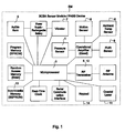
- the sensor module SM in accordance with one embodiment of the invention, as shown in Fig 1 , has the following parts and features:
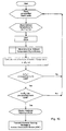
- the operation of the flashover warning software is described in the flow chart of the Fig. 15 .
- the rate of increase of ambient temperature is compared to the pre-specified alarm limit. If the rate of increase of ambient temperature is lower than the limit, the program returns to the beginning. If the rele of increase of ambient temperature is higher than the pre-specified alarm limit, a flashover warning is displayed in the HUD. A flashover warning is also transmitted to tha incident commander module;
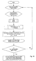
- the operation of the motion sensor program is described in the flow chart of the Fig. 17a and 17b , First the pre-specified alarm limits and the motion sensor are read and the real time clock is started. Then the motion is stored in to the memory as a function of time. If the motion slops, time period of zero motion is calculated.
- program If the time period of zero motion is shorter than the pre-specified limit, program returns to the beginning. Otherwise a countdown timer and a vibrator alarm are activated. Simultaneously zero motion warning and countdown timer data is displayed in the HUD. A zero motion warning is also transmitted to the incident commander module.
- the motion sensor is read again. If motion is detected, the countdown timer is reset and a all clear messaga is transmitted to the incident commander module, and the program returns to the beginning. Otherwise the countdown timer is checked, and if there is still time left, motion sensor is read again. If countdown timer has reached zero, an audible alarm is activated and an alarm message is trensmitted to the incident commander module.
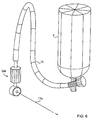
- the sensor module SM is attached to the pressure gage hose 15 of the air tank 2 as shown in Fig. 4 .
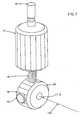
- the sensor module SM has a connector 16 to the pressure hose 15, a housing 17 for the electronic circuitry (shown in Fig. 1 ) of the sensor module SM , RF antenna 18, IR-sensor and ambient temperature sensor in their housing 19, a waterproof switch 10 for IR-sensor 9 ( Fig. 1 ), a laser 11 and SOS-button 20.
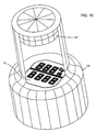
- the heads-up display HUD is an optielectric, night-readable display which is mounted in a facemask F of the firefighter, as shown in Fig, 8 and Fig. 9 .
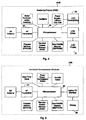
- the heads-up display module HUD as shown in Fig. 4 , has the following parts and features:
- the incident commander module ICM of one embodiment of the present invention provides the incident commander, who is commanding the operation, with real-time sensors data on all firefighters in the interior of the building or equivalent.
- the incident commander module ICM as shown in Fig. 5 and Fig. 14 has the following parts and features:
Description
- The present invention relates to a digital situation indicator, especially a personal monitoring and alarm system as defined in the preamble of claim 1.
- When entering a burning building, firefighters wear breathing apparatus consisting of an air tank, regulator, facemask and pressure gage. Typically, firefighters work in dense smoke, where the visibility may be only a few inches.
- Firefighters carry a personal alert safety system (PASS) device, which activates an audible alarm, if they stop moving. The PASS device has a "Pre-Alert" stage, which allows the firefighter a pre-specified number of seconds to move or to shake the PASS device, before the alarm is activated. In addition to the PASS device, firefighters need to know certain information about their constantly changing situation in order to safely and efficiently perform their work.
- At minimum, firefighters need to know at all times, how much air is remaining in their tank. The pressure of the air tank will only tell part of the story. Two firefighters with identical pressure gage readings may each have a different number of minutes of air time remaining, depending on their respective rates of air consumption. The rate of air consumption varies from firefighter to firefighter according to size, physical conditioning, and metabolic rate. The rate of air consumption also can change from minute to minute for an individual firefighter depending on the intensity of the physical work being performed, stress, and other factors. Therefore, the firefighter needs to know both the air pressure and its equivalent in number of minutes remaining, at any given time.
- For safety reasons, the firefighter also needs to know the ambient temperature, its time-dependent effect on his or her cumulative heat stress level, and whether flashover conditions are impending. Before opening a door inside a burning building, the firefighter needs to know whether there is a raging fire on the other side. During so-called "mop-up" operations after the fire has been extinguished, firefighters typically have to use axes to inspect inside walls, to ensure that no hidden fires exist.
-
DE-A-19822142 discloses a system for supervising user, such as a fireman, who carries respiratory equipment. The respiratory equipment carrier wears a mobile part which is connected to compressed air breather to assess and transfer data via a wireless connection to a remote base station, or a central station. The mobile part is connected by a cord to earphones or a loudspeaker at the helmet of the respiratory equipment carrier such that the mobile device is able to give an audible spoken notification on the remaining air pressure, or an audible spoken alarm. -
WO-A-93/03465 -
US-A-5886822 discloses that head mounted image displays may be used in helmets, goggles and eyeglasses. - Firefighters wear thick gloves, carry axes and water hoses, and need their hands free to be able to perform their work. Gages that attach to the air hose and hang from the firefighter's side are inconvenient to continuously pick-up and, in dense smoke, are almost impossible to read. When brought up to the facemask, the gage is too close for the firefighter's eyes to focus. For this reason, an elementary display system has recently been invented, consisting of a series of Light Emitting Diodes (LEDs) mounted inside the facemask. The drawback to this approach is that the LEDs provide much less information than gages provide.
- A helmet-mounted display system such as those used by military jet fighter pilots, which projects data onto the visor of the helmel, would offer firefighters a possible solution. However, the cost of a single helmet could absorb an annual budget. The cost to equip all firefighters worldwide would be staggering.
- The incident commander (IC) is in charge of all firefighters at the scene of the fire. Each firefighter gives the IC a personal accountability tag (PAT) upon arrival at the scene. The IC keeps track of the firefighters by the use of a unit identification pad (UIP) and a large marker board. The drawback is that once the firefighters are inside the fire, the IC has no method of knowing how much air each firefighter has left, what temperature the firefighters are operating in, what is their heal stress level or PASS device status.
- Firefighters, welders and warfighters are just examples for possible users of digital situation indicator of the invention. This kind of indicators can be utilised in many fields where personal monitoring and alarming are essential.
- Information systems, for example for divers, are known in the art. These systems include sensor modules, different kinds of display modules and also modules to send and receive data between the said modules. This kind of systems have been shown for instance in
US patent specifications 5503145 ,5301668 and5617848 . - These systems are, however, restricted in their properties and thus a system of the present invention brings quite many new, effective properties for improving the usefulness and safety of the system.
- A primary object of the present invention is to provide a digital situation indicator, especially a personal monitoring and alarm system that will overcome the shortcomings of the prior art devices. Another object of the invention is to provide a new digital situation indicator.
- The invention is characterized by the features defined in claim 1. The dependent claims describe preferred embodiments of the invention.
- The situation indicator SI of the invention offers a digital heads-up display HUD solution with a multitude of new features. The SI offers a truly digital, very easily legible HUD, at a cost no more expensive than the existing technology.
- The SI system has three separate units:
- Sensor Module SM for monitoring desired data,
- Heads-Up Display HUD mounted in the facemask F of the operating person, and Incident Commander Module ICM at a distance from the operating person.
- The sensor module may contain a pressure sensor, ambient temperature sensor, infrared (IR) temperature sensor, an "SOS" Button and an integrated PASS device. A microprocessor anelyses the sensor data and computes air time remaining in minutes, heal stress level, and impending flashover danger. The sensor module transmits sensor and computed data to both the HUD and the ICM. The communication between the parts is wireless such as radio frequency (RF) communication.
- The sensor module may also contain a amperage sensor. The sensor module transmits sensor and computed data to the HUD using wireless communication, such as RF communication.
- The heads-up display incorporates a miniature, transflective LCD display unit with electro-luminescent panel backlighting, and optical enhancement means consisting of an achromatic doublet lens, optimized to correct for on-axis spherical and chromatic aberrations. The optics is designed for extra long eye relief, and the HUD is positioned in the facamask so that it does not restrict the firefighter's forward field of view.
- With the SI system, before opening a door inside a burning building, the firefighter can point the IR sensor with a laser beam at the door, press the IR sensor button and read the temperature of the door on the HUD. During "mop-up" operations after the fire has been extinguished, the firefighter can scan the walls with the IR sensor to ensure that no hidden fires exist.
- The incident commander module consists of a self contained, portable, one-piece computer module, with backlit LCD display, louch screen or flex-membrane keypad, and RF transceiver. The ICM receives data transmissions from the sensor module. The ICM can also transmit text messages to the firefighler. Once the firefighter is inside the fire, the ICM tracks each firefighter's situation, including elapsed time in the fire, air pressure, air time remaining in minutes, ambient temperature in the fire, heat stress level and PASS device status.
- The advantages of the invention are, among the other things, the following:
- the SI system is a compact and versatile system for a user and, effective communication between different parts of the SI system, a user has clear and concise information for use,
- A preferred embodiments of the invention are presented in the following with reference to the attached drawing in which:
-
Fig. 1 shows a schematic block diagram of the sensor module according to the first embodiment of the invention, -
Fig. 2 shows a schematic block diagram of the sensor module according to another embodiment of the invention, -
Fig. 3 shows a schematic block diagrem of the sensor module according to another embodiment of the invention, -
Fig. 4 shows a block diagram of the heads-up display, -
Fig. 5 shows a block diagram of the incident commander module, -
Fig. 6 shows a perspective view of the sensor module attached to an air tank,Fig. 7 shows more closely the sensor module, -
Fig. 8 shows a mask with the heads-up display, -
Fig. 9 shows a welders helmet with the heads-up display, -
Fig. 10 shows more closely the heads-up display as perspective view, -
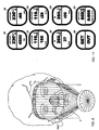
Fig. 11 shows examples of information which can be presented in the heads-up display according to the first embodiment of the invention, -
Fig. 12 show example of information which can be presented in the heads-up display according to another embodiment of the invention, -
Fig. 13 shows examples of information which can be presented in the heads-up display according to another embodiment of the invention, -
Fig. 14 shows a perspective view of the incident commander module, -
Fig. 15 shows a flow diagram of the Flashover Warning Alarm software according to the first embodiment of the invention, -
Fig. 16 shows a flow diagram of the Cumulative Heat Stress Level calculating software according to the first embodiment of the invention, and -
Fig. 17a and17b show a flow diagram of the Motion Sensor software according to the first embodiment of the invention. - Digital situation indicator SI for firefighters - system highlights:
- Pressure sensor -senses pressure remaining in the air tank of the firefighter;
- Computes minutes of air time remaining at firefighter's current consumption rate;
- Ambient température sensor - senses ambient temperature;
- Flashover warning alarm - warns of impending flashover danger;
- Computes heal stress level, in "degree-minutes";
- Integrated Personal Alert Safety System PASS device;
- Infrared (IR) sensor, activated by the push of a button - detects fire and/or high temperatures behind closed doors and inside walls;
- Visible light LASER to show where IR sensor is pointed;
- "SOS" button - transmits emergency signal to ICM and activates audible alarm;
- Service records datalogger - records sensor module service and maintenance information in non-volalile memory.
- The sensor module SM in accordance with one embodiment of the invention, as shown in
Fig 1 , has the following parts and features: - Sensor module SM scans all sensor readings and transmits updated sensor data to both HUD and ICM, preferably every 3 seconds;
- Pressure sensor 1- senses air pressure in the air tank 2 (
Fig. 6 ) ; - Control unit, such as
microprocessor 3, tracks firefighter's rate of air consumption, then computes air time remaining in minutes at current consumption rate; - Ambient temperature sensor 4 - senses ambient temperature;
- Flashover warning alarm - software analyses sensor data and detects, when ambient conditions are appropriate for impending flashover.
Microprocessor 3 transmits flashover warning to both HUD and ICM, and/or activatesaudible alarm 5. - The operation of the flashover warning software is described in the flow chart of the
Fig. 15 . First the pre-specified alarm limits and the ambient temperature TA are read and the real time clock is started. Then the ambient temperature is stored in to the memory as a function of time and the rate of increase of ambient temperature is calculated. After this the ambient temperature is compared to the pre-specified alarm limit and if the ambient temperature is lower than the limit, the program returns to the beginning. - If the ambient temperature is higher than pre-specified alarm limit, the rate of increase of ambient temperature is compared to the pre-specified alarm limit. If the rate of increase of ambient temperature is lower than the limit, the program returns to the beginning. If the rele of increase of ambient temperature is higher than the pre-specified alarm limit, a flashover warning is displayed in the HUD. A flashover warning is also transmitted to tha incident commander module;
-
Microprocessor 3 records firefighter's duration in high temperatures and compules cumulative heal stress level, in "degree-minutes". Software includes computelion for rehabilitation (Rehab) time as well asmultiple tank 2 usage. The operation of the cumulative heat stress level program is described in the flow chart of theFig. 16 . First the pre-specified alarm limits and the ambient temperature TA are read and the real time clock is sterted. Then the ambient temperature is stored in to the memory as a function of time and the cumulative heat stress level is calculated. After this the cumulative heat stress level is displayed in the HUD. - Integrated personal alert safety system "PASS" device, including: - Motion sensor 6 to detect absence of motion by firefighter; -
Vibrator 7 and/oraudible alarm 5 to alert firefighter of "Pre-Alert" condition; -Transmitter 8 to transmit "Pre-Alert" condition data to HUD and ICM; -Audible alarm 5, activated after a pre-specified number of seconds of absence of motion. - The operation of the motion sensor program is described in the flow chart of the
Fig. 17a and17b , First the pre-specified alarm limits and the motion sensor are read and the real time clock is started. Then the motion is stored in to the memory as a function of time. If the motion slops, time period of zero motion is calculated. - If the time period of zero motion is shorter than the pre-specified limit, program returns to the beginning. Otherwise a countdown timer and a vibrator alarm are activated. Simultaneously zero motion warning and countdown timer data is displayed in the HUD. A zero motion warning is also transmitted to the incident commander module.
- After this the motion sensor is read again. If motion is detected, the countdown timer is reset and a all clear messaga is transmitted to the incident commander module, and the program returns to the beginning. Otherwise the countdown timer is checked, and if there is still time left, motion sensor is read again. If countdown timer has reached zero, an audible alarm is activated and an alarm message is trensmitted to the incident commander module.
- Infrared (IR) sensor 9, activated by the push of a button 10 (
Fig. 9 ) - detects infrared radiation emitted from closed doors and walls (and therefore fire and/or high temperatures behind closed doors and inside walls) ; - Visible wavelength coaxial LASER 11 (
Fig. 7 ) to show with itsbeam 11a where IR-sensor 9 is pointed; - SOS-button 20 - activates audible alarm and transmits signal to ICM;
- Radio frequency (RF) receiver 12 - receives text messages from ICM and forwards them to HUD;
- Service records datalogger - records sensor module service and maintenance information in
non-volalile memory 13; - "Automatic On" feature - activated upon opening of air tank regulator valve;
- Optional button (s) 14 to allow firefighter to input his/her identification code.;
- Optional "Black Box" datalogger - records all sensor data during fire, with automatic "Time Slamping",
- Optional emergency locator transmitter (ELT), activated by PASS device or SOS-button.
- The sensor module SM is attached to the
pressure gage hose 15 of theair tank 2 as shown inFig. 4 . The sensor module SM has aconnector 16 to thepressure hose 15, ahousing 17 for the electronic circuitry (shown inFig. 1 ) of the sensor module SM ,RF antenna 18, IR-sensor and ambient temperature sensor in theirhousing 19, awaterproof switch 10 for IR-sensor 9 (Fig. 1 ), alaser 11 and SOS-button 20. - The heads-up display HUD is an optielectric, night-readable display which is mounted in a facemask F of the firefighter, as shown in
Fig, 8 andFig. 9 . The heads-up display module HUD, as shown inFig. 4 , has the following parts and features: - Control unit such as a
microprocessor 24,display 21, preferably electro-luminescent backlit 22, miniature digital LCD display or equivalent; - • Use of optical enhancement to create an easily legible digital display, which can be located inside the facemask as shown in
Fig. 8 as an example - specifically, anachromatic doublet lens 22, optimized to correct for on-axis spherical and chromatic aberrations, with extra long eye relief, positioned so as not to restrict the firefighter's forward field of view; - •
RF receiver 25 for receiving data from the sensor module SM; - •
Housing 23 into which thedisplay 21 and thelens 22 are fixed; - Pressure indicator - indicates pressure remaining in air tank;
- Time remaining indicator - indicates air time remaining in minutes, at current consumption rate;
- Heat stress indicator - displays firefighter's cumulative heat stress level;
- Flashover warning indicator - alerts firefighter of impending flashover danger;
- Infrared temperature indicator- displays infrared temperature of object that IR-sensor is pointed towards, whenever IR-sensor button is pushed (compare
Fig. 8 ) ; - PASS device condition indicator - alerts firefighter of "Pre-Alert" PASS condition;
- The display in accordance with another embodiment of the invention is arranged to function as following indicators:
- amperage indicator - indicates pressure remaining in air lank;
- The display in accordance with another embodiment of the invention is arranged to function as following indicators:
- CWA indicator - indicates consentration of CWA in the surrounding and changes the color of the display depending the situation;
- Time remaining indicator - indicates remaining operating time in minutes at current CWA consentration;
- "Sleep mode" -provides "Automatic On" feature and prolonged battery life;
- Optional two-way RF voice communication between firefighter and incident commander.
- The incident commander module ICM of one embodiment of the present invention provides the incident commander, who is commanding the operation, with real-time sensors data on all firefighters in the interior of the building or equivalent. The incident commander module ICM as shown in
Fig. 5 andFig. 14 , has the following parts and features: - Control unit such as a microprocessor 26;
-
RF Transceiver 27, which receives continuous RF sensor data transmissions from up to 128 firefighters, specifically from the firefighter's sensor modules SM; -
Display 28 such as backlit LCD display, indicates the following for each firefighter:- Elapsed time inside the fire;
- Pressure in air bank;
- Air time remaining in minute;
- Ambient tempereture reading;
- IR sensor reading;
- Heat stress level;
- Flashover warning;
- PASS device status, including "Pre-Alert" condition;
- Receives "SOS" transmission and identifies firefighter in trouble;
- Transmits text messages by means of the
RF transceiver 27 to any selected firefighter or to all firefighters; - Illuminates "Service" icons, to indicate when upcoming service is due for ICM, HUDs or sensor modules;
- "Black Box" datalogger built into ICM; - records each firefighter's situation in real-lime, as it occurs;
records any firefighter's "SOS" transmission in real-time, as it occurs; - records the ICM's text messages in real-time, as they occur; - records all service and maintenance records on each device;
automatically adds "Time/Date Stamp" to all records. - Field programming capacity - enables ICM to download identification codes and other information to non-volatile memory in sensor modules and HUDs;
- Optional two-way RF voice communication between firefighter and incident commander.
Claims (13)
- A digital situation indicator, especially a personal monitoring and/or alarm system, wherein the situation indicator (SI) has three separate units:a sensor module (SM) for monitoring desired data having sensors (1, 4, 6, 9; 32) for monitoring conditions in connection with the operating person and a control unit (3) for analyzing the data collected;a heads-up display module (HUD) mounted in a facemask (F) or helmet of the operating person for displaying the data;an incident commander module (ICM) at a distance from the operating person, for providing the incident commander with real-time sensors data on each operating person in the operating area;whereby the modules are arranged to communicate with each other,and having wireless communication means (8, 12, 27) in said modules (SM, HUD, ICM) for sending and receiving data between the sensor module (SM) and the heads-up display (HUD) module of the operating person and further between the sensor module and the incident commander module (ICM),sensor module (SM) further comprising- a flashover warning alarm for analyzing sensor data and detecting, when ambient conditions are appropriate for impending flashover,- means for computing cumulative heat stress level and heat stress warning alarm;- personal alert safety system (PASS) having motion sensor (6) and alarm (5; 7);- SOS button (20); and- radio frequency transceiver (8, 12) for transmitting sensor data, computed data and alarms to the heads-up display (HUD) module and/or an incident commander module (IGM) and receiving messages from the incident commander module (ICM); andthe incident commander module (ICM) further comprising- a control unit such as a microprocessor (26),- a radio frequency transceiver (27) for receiving sensor data transmissions and SOS transmissions from the fire fighters, especially from their sensor modules (SM) and for transmitting messages to any selected fire fighter or to all fire fighters and- display (28) for indicating information from the fire fighters.
- A digital situation indicator according to claim 1, characterized in that the sensor module includes an infrared temperature sensor (9) for detecting fire and/or high temperature behind closed doors and inside walls and a visible fight laser (11) to show with its beam where the sensor (9) is pointed.
- A digital situation indicator according to claim 2, characterized in that the infrared temperature sensor (9) has a switch (10) such as a button for activating the sensor.
- A digital situation indicator according to any of claims 1 - 3, characterized in that the sensor module (SM) has an emergency locator transmitter (ELT) activated by personal alert safety system (PASS) or SOS button (20).
- A digital situation indicator according to claim 1, characterized in that the sensor module (SM) is attachable to the pressure gage hose (15) of an air tank (2).
- A digital situation indicator according to any of claims 2 - 5, characterized in that the sensor module has two housings (17, 19) connected to each other, where the first housing (17) is for the electronic circuitry and the second housing (19) is or the coaxially arranged infrared temperature sensor (9) and laser (11) and further for the IR sensor activating switch (10) and SOS-button (20).
- A digital situation indicator according to claim 1, characterized in that the heads-up display (HUD) module has a control unit such as a microprocessor (24), a display, preferably electro-luminescent backlit (22) miniature, digital liquid crystal display (21), and optical enhancement means, specifically an achromatic doublet lens (22), optimized to correct for on-axis spherical and chromatic aberrations, which display (21) is positioned in a facemask or a helmet.
- A digital situation indicator according to claim 7, characterized in that the display (21) is arranged to function as the following indicators:- pressure indicator for indicating pressure remaining in the air tank;- time remaining indicator for indicating air remaining in minutes at current consumption rate;- ambient temperature indicator for displaying ambient temperatures;- heat stress indicator for displaying fire fighter's cumulative heat stress level; - flashover warning indicator for alerting the fire fighter of impending flashover danger;- personal alert safety system (PASS) device condition indicator for alerting the fire fighter of pre-alert condition; and- infrared temperature indicator for displaying infrared temperature of the object that the infrared temperature sensor (9) is pointed towards.
- A digital situation indicator according to any of preceding claims 1 - 8, characterized in that the heads-up display (HUD) module has a two-way radio frequency voice communication between any of the fire fighters and an incident commander by means of the incident commander module (ICM).
- A digital situation indicator according to any of preceding claims 1 - 9, characterized in that the incident commander module (ICM) is arranged to transmit text messages by means of the transceiver (27) to any selected fighter or to all the fighters.
- A digital situation indicator according to claim 1, characterized in that the display (28) of incident commander module (ICM) is arranged to indicate the following information for each fine fighters:- elapsed time inside the fire;- pressure in the air lank and air remaining in minutes;- ambient temperatura reading;- heat stress level;- flashover warning;- status of the personal alert safety system (PASS) device; and- reading of the infrared temperature sensor (9) and for each war fighter:- elapsed time under chemical warfare agent;- chemical warfare agent concentration in the surroundings;- current dosage of chemical warfare agent; and- remaining operating time in minutes.
- A digital situation indicator according to any of preceding claims 1 - 11, characterized in that the incident commander module (ICM) has a datalogger which is arranged to record the following information- each fighter's situation in real-time, as it occurs;- any fighter's SOS transmission on real-time, as it occurs;- all service and maintenance records on each device; and- automatically to add time/date stamp to all records.
- A digital situation indicator according to any of preceding claims 1 - 12, characterized in that the incident commander module (ICM) has field programming capacity, which enables the ICM to download identification codes and other information from the incident commander module (ICM) to the sensor module (SM) and the heads-up display (HUD) module of the fighter.
Applications Claiming Priority (3)
| Application Number | Priority Date | Filing Date | Title |
|---|---|---|---|
| FI20001563A FI20001563A0 (en) | 2000-06-30 | 2000-06-30 | Status indicator for civil protection |
| FI20001563 | 2000-06-30 | ||
| PCT/FI2001/000626 WO2002002191A1 (en) | 2000-06-30 | 2001-07-02 | Digital situation indicator |
Publications (2)
| Publication Number | Publication Date |
|---|---|
| EP1296745A1 EP1296745A1 (en) | 2003-04-02 |
| EP1296745B1 true EP1296745B1 (en) | 2012-09-12 |
Family
ID=8558689
Family Applications (1)
| Application Number | Title | Priority Date | Filing Date |
|---|---|---|---|
| EP01951754A Expired - Lifetime EP1296745B1 (en) | 2000-06-30 | 2001-07-02 | Digital situation indicator |
Country Status (5)
| Country | Link |
|---|---|
| EP (1) | EP1296745B1 (en) |
| AU (1) | AU2001272609A1 (en) |
| CA (1) | CA2414891A1 (en) |
| FI (1) | FI20001563A0 (en) |
| WO (1) | WO2002002191A1 (en) |
Cited By (1)
| Publication number | Priority date | Publication date | Assignee | Title |
|---|---|---|---|---|
| US9508248B2 (en) | 2014-12-12 | 2016-11-29 | Motorola Solutions, Inc. | Method and system for information management for an incident response |
Families Citing this family (19)
| Publication number | Priority date | Publication date | Assignee | Title |
|---|---|---|---|---|
| US7089930B2 (en) | 2002-08-20 | 2006-08-15 | Audiopack Technologies, Inc. | Wireless heads-up display for a self-contained breathing apparatus |
| GB2427732A (en) * | 2005-06-28 | 2007-01-03 | Cohen Ellis B | Personal monitor |
| CA2683278A1 (en) | 2007-05-18 | 2008-11-27 | 3M Innovative Properties Company | Method for tracking cyclical procedures performed on personal protection equipment |
| EP3236397A1 (en) | 2007-05-18 | 2017-10-25 | 3M Innovative Properties Company | Verfahren zur verfolgung von method for tracking procedures performed on personal protection equipment and actions of individuals |
| WO2008156470A1 (en) * | 2007-06-21 | 2008-12-24 | Eugene Greco | Heat sensor device and system |
| EP3461536B1 (en) | 2007-08-31 | 2020-08-12 | 3M Innovative Properties Company | Determining conditions of components removably coupled to personal protection equipment |
| US20090058600A1 (en) | 2007-08-31 | 2009-03-05 | 3M Innovative Properties Company | Determining compatibility of components for assembling approved personal protection configurations |
| BRPI0815255B1 (en) | 2007-08-31 | 2019-03-19 | 3M Innovative Properties Company | METHOD FOR DETERMINING A CONDITION OF AT LEAST A PERSONAL PROTECTION ARTICLE AND A DETERMINATION SYSTEM IF A PERSONAL PROTECTION ARTICLE MEETS AT LEAST A PRE-DETERMINED CRITERIA |
| BRPI0815253A2 (en) | 2007-08-31 | 2015-02-10 | 3M Innovative Properties Co | "TRACKING METHOD AND DETERMINATION SYSTEM" |
| DE212011100096U1 (en) * | 2010-05-21 | 2013-01-10 | Scott Health & Safety Ltd. | Entry control management system for displaying a firefighting status on an electronic control panel and a digital pressure gauge |
| GB2503016B (en) * | 2012-06-14 | 2017-10-04 | Draeger Safety Uk Ltd | A telemetry monitoring system and a data recovery method for a telemetry monitoring system |
| US9999546B2 (en) | 2014-06-16 | 2018-06-19 | Illinois Tool Works Inc. | Protective headwear with airflow |
| WO2016001651A1 (en) * | 2014-06-30 | 2016-01-07 | Boffey John Robert | Powered air purifying respirator |
| KR102375215B1 (en) | 2016-03-07 | 2022-03-16 | 쓰리엠 이노베이티브 프로퍼티즈 캄파니 | Intelligent safety monitoring and analysis system for personal protective equipment |
| GB2551172B (en) | 2016-06-08 | 2019-02-20 | Sts Defence Ltd | Predicting temperature rise event |
| US10682721B2 (en) | 2016-07-14 | 2020-06-16 | Lincoln Global, Inc. | Method and system for welding with temperature detector |
| US10354350B2 (en) | 2016-10-18 | 2019-07-16 | Motorola Solutions, Inc. | Method and system for information management for an incident response |
| US11812816B2 (en) | 2017-05-11 | 2023-11-14 | Illinois Tool Works Inc. | Protective headwear with airflow |
| CA3089011A1 (en) * | 2018-01-17 | 2019-07-25 | Decon7 Systems, Llc | Surface decontamination formulation |
Family Cites Families (3)
| Publication number | Priority date | Publication date | Assignee | Title |
|---|---|---|---|---|
| US5301668A (en) | 1991-06-20 | 1994-04-12 | Hales Lynn B | Field of view underwater diving computer monitoring and display system |
| US5503145A (en) | 1992-06-19 | 1996-04-02 | Clough; Stuart | Computer-controlling life support system and method for mixed-gas diving |
| US5617848A (en) | 1993-11-17 | 1997-04-08 | Cochran; Michael J. | Advanced dive computer that calculates and displays the user's breathing parameter and water salinity |
-
2000
- 2000-06-30 FI FI20001563A patent/FI20001563A0/en unknown
-
2001
- 2001-07-02 EP EP01951754A patent/EP1296745B1/en not_active Expired - Lifetime
- 2001-07-02 WO PCT/FI2001/000626 patent/WO2002002191A1/en active Application Filing
- 2001-07-02 AU AU2001272609A patent/AU2001272609A1/en not_active Abandoned
- 2001-07-02 CA CA002414891A patent/CA2414891A1/en not_active Abandoned
Cited By (1)
| Publication number | Priority date | Publication date | Assignee | Title |
|---|---|---|---|---|
| US9508248B2 (en) | 2014-12-12 | 2016-11-29 | Motorola Solutions, Inc. | Method and system for information management for an incident response |
Also Published As
| Publication number | Publication date |
|---|---|
| WO2002002191A1 (en) | 2002-01-10 |
| EP1296745A1 (en) | 2003-04-02 |
| CA2414891A1 (en) | 2002-01-10 |
| AU2001272609A1 (en) | 2002-01-14 |
| FI20001563A0 (en) | 2000-06-30 |
Similar Documents
| Publication | Publication Date | Title |
|---|---|---|
| US7298535B2 (en) | Digital situation indicator | |
| EP1296745B1 (en) | Digital situation indicator | |
| US10042164B2 (en) | Self contained breathing apparatus (SCBA) electronics system | |
| JP6488394B2 (en) | Wearable communication assembly and communication assembly | |
| US20080023002A1 (en) | Head safety device with integrated display | |
| US8212211B2 (en) | System for protecting and/or guiding persons in dangerous situations | |
| US6720878B2 (en) | Data communications system for mask or helmet users | |
| US7342210B2 (en) | Remote control for auto-darkening lens systems and method | |
| EP2394253B1 (en) | Emergency call device | |
| US10688325B2 (en) | Eye-protective shield with head up display | |
| JPH0854282A (en) | Head-mounted display device | |
| CN110673739A (en) | Method for realizing intelligent safety protection wearable equipment for firefighter emergency rescue | |
| US11113942B1 (en) | Human awareness telemetry apparatus, systems, and methods | |
| CN109512074B (en) | Novel fire-fighting helmet based on optical waveguide display technology | |
| KR20150102328A (en) | Personal air breathing device with safety alarm function and worker management system | |
| CN108388012A (en) | A kind of intelligent fire breathing mask glasses that Multi-information acquisition is shown | |
| US20140375459A1 (en) | Firefighter's safety monitoring and alarm | |
| US6447115B1 (en) | Dive mask with integrated monitoring system | |
| US6837240B1 (en) | Display system upgrade for a full face mask | |
| US11915376B2 (en) | Wearable assisted perception module for navigation and communication in hazardous environments | |
| CN210639588U (en) | Intelligent safety protection wearing equipment for firefighter emergency rescue | |
| KR101517608B1 (en) | Emergency navigational smoke helmet | |
| US11011040B2 (en) | Electronic personal dosimeter smart accessory system | |
| CN107660157B (en) | Self-contained breathing apparatus with thermal imaging capability | |
| WO2016205053A1 (en) | Self contained breathing apparatus (scba) electronics system |
Legal Events
| Date | Code | Title | Description |
|---|---|---|---|
| PUAI | Public reference made under article 153(3) epc to a published international application that has entered the european phase |
Free format text: ORIGINAL CODE: 0009012 |
|
| 17P | Request for examination filed |
Effective date: 20030115 |
|
| AK | Designated contracting states |
Designated state(s): AT BE CH CY DE DK ES FI FR GB GR IE IT LI LU MC NL PT SE TR Kind code of ref document: A1 Designated state(s): AT BE CH CY DE DK ES FI FR GB GR IE IT LI LU MC NL PT SE TR |
|
| AX | Request for extension of the european patent |
Extension state: AL LT LV MK RO SI |
|
| 17Q | First examination report despatched |
Effective date: 20060925 |
|
| RAP1 | Party data changed (applicant data changed or rights of an application transferred) |
Owner name: KUUTTI, TOM L. |
|
| RIN1 | Information on inventor provided before grant (corrected) |
Inventor name: KUUTTI, TOM L. |
|
| RAP1 | Party data changed (applicant data changed or rights of an application transferred) |
Owner name: KUUTTI, TOM L. |
|
| RIN1 | Information on inventor provided before grant (corrected) |
Inventor name: KUUTTI, TOM L. |
|
| GRAP | Despatch of communication of intention to grant a patent |
Free format text: ORIGINAL CODE: EPIDOSNIGR1 |
|
| GRAS | Grant fee paid |
Free format text: ORIGINAL CODE: EPIDOSNIGR3 |
|
| GRAA | (expected) grant |
Free format text: ORIGINAL CODE: 0009210 |
|
| AK | Designated contracting states |
Kind code of ref document: B1 Designated state(s): AT BE CH CY DE DK ES FI FR GB GR IE IT LI LU MC NL PT SE TR |
|
| REG | Reference to a national code |
Ref country code: GB Ref legal event code: FG4D |
|
| REG | Reference to a national code |
Ref country code: CH Ref legal event code: EP |
|
| REG | Reference to a national code |
Ref country code: AT Ref legal event code: REF Ref document number: 574757 Country of ref document: AT Kind code of ref document: T Effective date: 20120915 |
|
| REG | Reference to a national code |
Ref country code: IE Ref legal event code: FG4D |
|
| REG | Reference to a national code |
Ref country code: DE Ref legal event code: R096 Ref document number: 60147108 Country of ref document: DE Effective date: 20121108 |
|
| PG25 | Lapsed in a contracting state [announced via postgrant information from national office to epo] |
Ref country code: CY Free format text: LAPSE BECAUSE OF FAILURE TO SUBMIT A TRANSLATION OF THE DESCRIPTION OR TO PAY THE FEE WITHIN THE PRESCRIBED TIME-LIMIT Effective date: 20120912 |
|
| REG | Reference to a national code |
Ref country code: NL Ref legal event code: VDEP Effective date: 20120912 |
|
| REG | Reference to a national code |
Ref country code: AT Ref legal event code: MK05 Ref document number: 574757 Country of ref document: AT Kind code of ref document: T Effective date: 20120912 |
|
| PG25 | Lapsed in a contracting state [announced via postgrant information from national office to epo] |
Ref country code: GR Free format text: LAPSE BECAUSE OF FAILURE TO SUBMIT A TRANSLATION OF THE DESCRIPTION OR TO PAY THE FEE WITHIN THE PRESCRIBED TIME-LIMIT Effective date: 20121213 Ref country code: SE Free format text: LAPSE BECAUSE OF FAILURE TO SUBMIT A TRANSLATION OF THE DESCRIPTION OR TO PAY THE FEE WITHIN THE PRESCRIBED TIME-LIMIT Effective date: 20120912 |
|
| PG25 | Lapsed in a contracting state [announced via postgrant information from national office to epo] |
Ref country code: BE Free format text: LAPSE BECAUSE OF FAILURE TO SUBMIT A TRANSLATION OF THE DESCRIPTION OR TO PAY THE FEE WITHIN THE PRESCRIBED TIME-LIMIT Effective date: 20120912 Ref country code: ES Free format text: LAPSE BECAUSE OF FAILURE TO SUBMIT A TRANSLATION OF THE DESCRIPTION OR TO PAY THE FEE WITHIN THE PRESCRIBED TIME-LIMIT Effective date: 20121223 Ref country code: NL Free format text: LAPSE BECAUSE OF FAILURE TO SUBMIT A TRANSLATION OF THE DESCRIPTION OR TO PAY THE FEE WITHIN THE PRESCRIBED TIME-LIMIT Effective date: 20120912 |
|
| PG25 | Lapsed in a contracting state [announced via postgrant information from national office to epo] |
Ref country code: PT Free format text: LAPSE BECAUSE OF FAILURE TO SUBMIT A TRANSLATION OF THE DESCRIPTION OR TO PAY THE FEE WITHIN THE PRESCRIBED TIME-LIMIT Effective date: 20130114 |
|
| PG25 | Lapsed in a contracting state [announced via postgrant information from national office to epo] |
Ref country code: AT Free format text: LAPSE BECAUSE OF FAILURE TO SUBMIT A TRANSLATION OF THE DESCRIPTION OR TO PAY THE FEE WITHIN THE PRESCRIBED TIME-LIMIT Effective date: 20120912 |
|
| PLBE | No opposition filed within time limit |
Free format text: ORIGINAL CODE: 0009261 |
|
| STAA | Information on the status of an ep patent application or granted ep patent |
Free format text: STATUS: NO OPPOSITION FILED WITHIN TIME LIMIT |
|
| PG25 | Lapsed in a contracting state [announced via postgrant information from national office to epo] |
Ref country code: DK Free format text: LAPSE BECAUSE OF FAILURE TO SUBMIT A TRANSLATION OF THE DESCRIPTION OR TO PAY THE FEE WITHIN THE PRESCRIBED TIME-LIMIT Effective date: 20120912 |
|
| 26N | No opposition filed |
Effective date: 20130613 |
|
| PG25 | Lapsed in a contracting state [announced via postgrant information from national office to epo] |
Ref country code: IT Free format text: LAPSE BECAUSE OF FAILURE TO SUBMIT A TRANSLATION OF THE DESCRIPTION OR TO PAY THE FEE WITHIN THE PRESCRIBED TIME-LIMIT Effective date: 20120912 |
|
| REG | Reference to a national code |
Ref country code: DE Ref legal event code: R097 Ref document number: 60147108 Country of ref document: DE Effective date: 20130613 |
|
| PGFP | Annual fee paid to national office [announced via postgrant information from national office to epo] |
Ref country code: DE Payment date: 20130801 Year of fee payment: 13 |
|
| PGFP | Annual fee paid to national office [announced via postgrant information from national office to epo] |
Ref country code: FR Payment date: 20130731 Year of fee payment: 13 Ref country code: GB Payment date: 20130731 Year of fee payment: 13 |
|
| PG25 | Lapsed in a contracting state [announced via postgrant information from national office to epo] |
Ref country code: MC Free format text: LAPSE BECAUSE OF FAILURE TO SUBMIT A TRANSLATION OF THE DESCRIPTION OR TO PAY THE FEE WITHIN THE PRESCRIBED TIME-LIMIT Effective date: 20120912 |
|
| REG | Reference to a national code |
Ref country code: CH Ref legal event code: PL |
|
| REG | Reference to a national code |
Ref country code: IE Ref legal event code: MM4A |
|
| PG25 | Lapsed in a contracting state [announced via postgrant information from national office to epo] |
Ref country code: FI Free format text: LAPSE BECAUSE OF NON-PAYMENT OF DUE FEES Effective date: 20130702 Ref country code: CH Free format text: LAPSE BECAUSE OF NON-PAYMENT OF DUE FEES Effective date: 20130731 Ref country code: LI Free format text: LAPSE BECAUSE OF NON-PAYMENT OF DUE FEES Effective date: 20130731 |
|
| PG25 | Lapsed in a contracting state [announced via postgrant information from national office to epo] |
Ref country code: IE Free format text: LAPSE BECAUSE OF NON-PAYMENT OF DUE FEES Effective date: 20130702 |
|
| REG | Reference to a national code |
Ref country code: DE Ref legal event code: R119 Ref document number: 60147108 Country of ref document: DE |
|
| GBPC | Gb: european patent ceased through non-payment of renewal fee |
Effective date: 20140702 |
|
| REG | Reference to a national code |
Ref country code: FR Ref legal event code: ST Effective date: 20150331 |
|
| PG25 | Lapsed in a contracting state [announced via postgrant information from national office to epo] |
Ref country code: DE Free format text: LAPSE BECAUSE OF NON-PAYMENT OF DUE FEES Effective date: 20150203 |
|
| REG | Reference to a national code |
Ref country code: DE Ref legal event code: R119 Ref document number: 60147108 Country of ref document: DE Effective date: 20150203 |
|
| PG25 | Lapsed in a contracting state [announced via postgrant information from national office to epo] |
Ref country code: FR Free format text: LAPSE BECAUSE OF NON-PAYMENT OF DUE FEES Effective date: 20140731 Ref country code: GB Free format text: LAPSE BECAUSE OF NON-PAYMENT OF DUE FEES Effective date: 20140702 |
|
| PG25 | Lapsed in a contracting state [announced via postgrant information from national office to epo] |
Ref country code: TR Free format text: LAPSE BECAUSE OF FAILURE TO SUBMIT A TRANSLATION OF THE DESCRIPTION OR TO PAY THE FEE WITHIN THE PRESCRIBED TIME-LIMIT Effective date: 20120912 |
|
| PG25 | Lapsed in a contracting state [announced via postgrant information from national office to epo] |
Ref country code: LU Free format text: LAPSE BECAUSE OF NON-PAYMENT OF DUE FEES Effective date: 20130702 |