EP1296548A2 - Parts arranging method and parts mounting apparatus - Google Patents
Parts arranging method and parts mounting apparatus Download PDFInfo
- Publication number
- EP1296548A2 EP1296548A2 EP02020112A EP02020112A EP1296548A2 EP 1296548 A2 EP1296548 A2 EP 1296548A2 EP 02020112 A EP02020112 A EP 02020112A EP 02020112 A EP02020112 A EP 02020112A EP 1296548 A2 EP1296548 A2 EP 1296548A2
- Authority
- EP
- European Patent Office
- Prior art keywords
- parts
- mounting
- electronic parts
- calculated
- storage units
- Prior art date
- Legal status (The legal status is an assumption and is not a legal conclusion. Google has not performed a legal analysis and makes no representation as to the accuracy of the status listed.)
- Withdrawn
Links
- 238000000034 method Methods 0.000 title claims description 14
- 239000000758 substrate Substances 0.000 claims description 13
- 230000032258 transport Effects 0.000 claims description 3
- 238000009826 distribution Methods 0.000 description 11
- 238000010586 diagram Methods 0.000 description 4
- 238000007796 conventional method Methods 0.000 description 1
- 230000005484 gravity Effects 0.000 description 1
- 238000004904 shortening Methods 0.000 description 1
Images



Classifications
-
- H—ELECTRICITY
- H05—ELECTRIC TECHNIQUES NOT OTHERWISE PROVIDED FOR
- H05K—PRINTED CIRCUITS; CASINGS OR CONSTRUCTIONAL DETAILS OF ELECTRIC APPARATUS; MANUFACTURE OF ASSEMBLAGES OF ELECTRICAL COMPONENTS
- H05K13/00—Apparatus or processes specially adapted for manufacturing or adjusting assemblages of electric components
- H05K13/08—Monitoring manufacture of assemblages
- H05K13/085—Production planning, e.g. of allocation of products to machines, of mounting sequences at machine or facility level
-
- H—ELECTRICITY
- H05—ELECTRIC TECHNIQUES NOT OTHERWISE PROVIDED FOR
- H05K—PRINTED CIRCUITS; CASINGS OR CONSTRUCTIONAL DETAILS OF ELECTRIC APPARATUS; MANUFACTURE OF ASSEMBLAGES OF ELECTRICAL COMPONENTS
- H05K13/00—Apparatus or processes specially adapted for manufacturing or adjusting assemblages of electric components
- H05K13/08—Monitoring manufacture of assemblages
- H05K13/085—Production planning, e.g. of allocation of products to machines, of mounting sequences at machine or facility level
- H05K13/0853—Determination of transport trajectories inside mounting machines
Definitions
- the present invention relates to a parts arranging method for determining a storage unit in which electronic parts to be mounted should be placed in a parts mounting apparatus for mounting electronic parts to be mounted which are stored in storage units in advance to a substrate such as a printed circuit board using a mounting head.
- FIG. 1 is a schematic diagram which shows an operating state of a parts mounting apparatus which mounts electronic parts to a printed circuit board.
- denoted by 1 is a printed circuit board to which electronic parts are mounted at predetermined mounting points 1a through 1c.
- the printed circuit board 1 is transported by a transportation mechanism (not shown) and set at a predetermined position.
- a transportation mechanism not shown
- identical types of electronic parts are mounted at the mounting points on the printed circuit board 1 denoted by the same reference symbol.
- electronic parts A are mounted to the three mounting points 1a
- electronic parts B are mounted to the two mounting points 1b
- an electronic part C is mounted to the mounting point 1c.
- a plurality of (six in this example) feeders (parts storage units) 2a through 2f storing electronic parts which are to be mounted to the printed circuit board 1 are arranged in a row.
- Each one of the feeders 2a through 2f stores one type of electronic parts.
- electronic parts A, B, ..., F are stored in the feeders 2a, 2b, ..., 2f, respectively.
- a mounting head 3 which moves in two dimensions (XY system) by means of a predetermined drive mechanism (not shown).
- the mounting head 3 moves between the printed circuit board 1 and the respective feeders 2a through 2f and mounts the electronic parts to the printed circuit board 1.
- the mounting head 3 moves to the feeder 2a which stores the electronic parts A, sucks and takes out the electronic parts A stored in the feeder 2a, and thereafter moves to the mounting point 1a on the printed circuit board 1 and mounts the sucked electronic part A at the mounting point 1a. Similar operations are repeated following this, whereby the corresponding electronic parts A through C are mounted one after another at all mounting points 1a through 1c.
- a conventional approach for reduction of the mounting time demands that electronic parts which are to be mounted at a certain mounting point are stored in a feeder which is at a shortest distance from the coordinate position of the mounting point (When one type needs be mounted at more than one mounting point, this type of electronic parts are stored in a feeder which is at a shortest distance from an average value (center of gravity position) of the coordinate positions of those mounting points.).
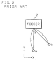
- the conventional method above has a problem that the mounting time may not always be shortened because the feeder for storing is determined based on the distance between the mounting point(s) and the feeder. As shown in FIG. 2, when distances (L) from two mounting points a and b to a certain feeder 2 are equal, movement times for a mounting head to move from these two mounting points a and b to the feeder 2 are different from each other.
- the mounting head can be driven independently in an X-direction and a Y-direction for instance and can move in the X-direction and the Y-direction at the same time, on the assumption that the mounting head moves at the same speed each in the X-direction and the Y-direction, even if the distances (L) to the feeder 2 are equal, the movement time T a and T b from the mounting points a and b are expressed by the following formulas (1) and (2).
- T a L/v Y
- T b max(Lsin ⁇ /v X , Lcos ⁇ /v Y )
- the distance from the mounting point to the feeder is not proportional to the movement time of the mounting head or does not accurately reflect the movement time, and therefore, it cannot be said that the feeder is efficiently determined according to the conventional approach and the mounting time is not always shortened.
- a principal object of the present invention is to provide a parts arranging method and a parts mounting apparatus with which it is possible to determine storage units (feeders) considering the movement time of a mounting head, efficiently determine the storage units (feeders) and accordingly reduce time for mounting parts without fail.
- a parts arranging method for determining a storage unit to store parts for a parts mounting apparatus in which a plurality of storage units each storing one type of parts and a substrate to which the parts are mounted at a plurality of mounting points are disposed at predetermined positions, and a mounting head moves, accordingly transports a corresponding part from the storage units and mounts the part to the substrate
- the parts arranging method is characterized in comprising the steps of calculating movement time for the mounting head to move from the respective mounting points on the substrate to the respective storage units; calculating, for each one of the storage units, the total of a plurality of lengths of movement time calculated for the respective mounting points; and determining a storage unit which is to store the parts based on the calculated total time.
- the movement time of the mounting head to travel from the respective mounting points on the substrate to the respective storage units is calculated, and the total of the movement time calculated for the respective mounting points is calculated for each storage unit.
- the storage unit for which the total time is the shortest is determined as a storage unit which is to store the corresponding type of parts. Since the storage unit is determined considering the movement time of the mounting head, which is directly linked to the mounting time of the parts, it is possible to determine the storage unit so as to reliably shorten the mounting time of the parts.
- the present invention is characterized in that at the stage of determining the storage units which are to store the plurality of types of parts, a storage unit which is to store the parts which are to be mounted in greater number is given priority.
- a storage unit is determined for parts which are to be mounted in greater number with a higher priority than for those parts which are to be mounted in a small number.
- processing for determining the storage units according to the first aspect of the invention is executed for each of a plurality of types of parts, storage units to be determined may overlap in some cases.
- a storage unit is set for the parts to be mounted in greater number, namely, for those parts which are to be mounted at a greater number of mounting points on the substrate. In this manner, it is possible to efficiently determine the storage parts for the plurality of types of electronic parts.
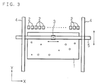
- FIG. 3 is a schematic diagram which shows an operating state of a parts mounting apparatus to which a parts arranging method according to the present invention is applied.
- denoted by 1 is a printed circuit board to which electronic parts are mounted at predetermined mounting points (which are denoted by o, ⁇ , ⁇ , ⁇ ).
- the printed circuit board 1 is transported by a transportation mechanism (not shown) and set at a predetermined position.
- the same type of electronic parts are mounted.
- feeders parts storage units 2 2, 2, ..., 2 which store electronic parts to be mounted to the printed circuit board 1 are arranged in a row.
- Each one of the feeders 2 stores one type of electronic parts. In this example, a maximum of eighteen types of electronic parts in total can be stored.
- a rod-like beam 5 stretches across paired rails 4 and 4 which are opposed to each other, and the mounting head 3 is provided on the beam 5.
- the beam 5 can move in the Y-direction along the rails 4 and 4.
- the mounting head 3 provided on the beam 5 can move in the X-direction along the beam 5.
- the X-direction drive motor and the Y-direction drive motor can be driven independently, so that the mounting head 3 can move in the X-direction and the Y-direction independently at the same time.
- the mounting head 3 mounts corresponding electronic parts to the respective mounting portions on the printed circuit board 1.
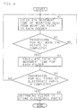
- FIG. 4 is a flowchart which shows the sequence of processing in the method
- FIG. 5 through FIG. 9 are drawings for illustrating operations according to the method.
- An example will be described as a first preferred embodiment in which one type of electronic parts (electronic parts A) is to be set to the printed circuit board 1, and the electronic parts A are to be mounted to the printed circuit board 1 at three mounting points (a1, a2, a3), and an optimal feeder 2 is determined from among eighteen feeders 2, 2, ..., 2 so as to store the electronic parts A.
- one type of electronic parts electronic parts A
- the electronic parts A are to be mounted to the printed circuit board 1 at three mounting points (a1, a2, a3)
- an optimal feeder 2 is determined from among eighteen feeders 2, 2, ..., 2 so as to store the electronic parts A.
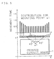
- FIG. 5 shows a positional relationship between the mounting point a1 and the feeders 2 and a distribution of the movement time (bar chart).
- the mounting head 3 can move in the X-direction and the Y-direction independently at the same time, the movement time to the eleven feeders 2 located in a central area which is within the region denoted by the dashed lines in FIG. 5 are the shortest time (0.5 second) which is constant.
- the movement time to all feeders 2 which are in the range from -45 degrees to 45 degrees with respect to the Y-direction from the mounting point a1 is the constant shortest time.
- Step S2 since processing for calculating the movement time to all mounting points is not yet complete (Step S2 : NO), the movement time of the mounting head 3 to each of the eighteen feeders 2, 2, ..., 2 from the mounting point a2 on the printed circuit board 1 is calculated (S1).
- FIG. 6 shows a positional relationship between the mounting point a2 and the feeders 2 and a distribution of the movement time.
- FIG. 7 shows a positional relationship between the mounting point a3 and the feeders 2 and a distribution of the movement time.
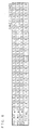
- FIG. 8 shows, for each one of the eighteen feeders 2, 2, ..., 2, the movement time at the respective mounting points a1, a2 and a3 and the total movement time in the form of a table.
- Step S4 the processing for all types of electronic parts is now complete (Step S4 : YES), and therefore, an optimal feeder 2 which is to store the electronic parts A is determined based on the sum of the movement time distributions calculated at S3 (total of the movement time) (Step S5).
- the feeder 2 (the ninth feeder 2 from the extreme left) for which the total time shown in FIG. 8 is the shortest (1.6 seconds) is determined as an optimal feeder 2.
- An example will be described as a second preferred embodiment in which four types of electronic parts (electronic parts A, B, C, D)are set to the printed circuit board 1, and the electronic parts A, B, C and D are to be mounted to the printed circuit board 1 respectively at twenty mounting points, fifteen mounting points, eight mounting points and four mounting points, and an optimal feeder is determined from among four feeders F1, F2, F3 and F4 for each one of the four types of electronic parts A, B, C and D.
- the feeders correspond to the four types of electronic parts A, B, C and D in a 1 : 1 relationship and the four types of electronic parts are allotted to four feeders.
- a distribution of movement time to the twenty mounting points is calculated for the electronic parts A (S1, S2), and the sum of these (total of movement time) is then calculated (S3). Since processing for all types of electronic parts is not yet complete (S4 : NO), distributions of movement time for the electronic parts B, C and D are calculated (S1, S2), and the sum of these (total of movement time) is then calculated (S3).
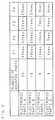
- FIG. 9 shows, for each one of the feeders F1, F2, F3 and F4, one example of the total time of the movement time for the electronic parts A, B, C and D.
- While a feeder associated with the shortest total time is basically determined in a similar manner to that of the first preferred embodiment, an optimal feeder is determined for electronic parts which are to be mounted in greater number with a higher priority.
- the feeder F3 associated with the shortest total time 22 seconds
- the feeder F1 associated with the shortest total time 18 seconds
- the feeder F4 associated with the next shortest total time 9 seconds
- the feeder F3 associated with the shortest total time (4 seconds) is optimal
- the feeder F2 associated with the next shortest total time (5 seconds) is set since the feeder F3 is already assigned for the electronic parts A.
- the feeders are determined more efficiently.
- the feeders may be determined such that the total sum of all movement time becomes the shortest as if to solve a minimization question using a combination optimizing scheme, at the stage of determining optimal feeders for a plurality of types of electronic parts.
- the movement time required for the mounting head to move from the respective mounting points on the substrate to the respective storage units is calculated, the total movement time calculated for the plurality of mounting points is calculated for each storage unit, and a storage unit to store these parts is determined based on the calculated total time according to the present invention.
- the storage units are set considering the movement time of the mounting head directly linked to the mounting time of the parts, it is possible to shorten the mounting time of the parts without fail.
Landscapes
- Engineering & Computer Science (AREA)
- Operations Research (AREA)
- Manufacturing & Machinery (AREA)
- Microelectronics & Electronic Packaging (AREA)
- Supply And Installment Of Electrical Components (AREA)
Abstract
Description
Claims (4)
- A parts arranging method for determining a storage unit (2) to store parts in a parts mounting apparatus in which a plurality of storage units (2) each storing one type of parts and a substrate (1) to which said parts are mounted at a plurality of mounting points (a1, a2, a3) are disposed at predetermined positions, and a mounting head (3) moves, accordingly transports a corresponding part from said storage units (2) and mounts the part to said substrate (1), said method being characterized in that movement time for said mounting head (3) to move from said respective mounting points (a1, a2, a3) on said substrate (1) to said respective storage units (2) is calculated, the total of a plurality of lengths of movement time calculated for said respective mounting points (a1, a2, a3) is calculated for each one of said storage units, and a storage unit (2) which is to store said parts is determined based on the calculated total time.
- The parts arranging method according to Claim 1, wherein at the stage of determining said storage units (2) which are to store a plurality of types of parts, a storage unit (2) which is to store parts which are to be mounted in a great number is given priority.
- A parts mounting apparatus which mounts parts to a substrate (1) at a plurality of mounting points (a1, a2, a3), characterized in comprising: a plurality of storage units (2) each storing one type of said parts; a mounting head (3) which transports a corresponding part from said storage units (2) and mounts the part to said substrate (1); a drive mechanism (4, 5) which drives said mounting head (3); and a determining unit which calculates movement time for said mounting head (3) to move from said respective mounting points (a1, a2, a3) on said substrate (1) to said respective storage units (2), calculates for each one of said storage units (2) the total of a plurality of lengths of movement time calculated for said respective mounting points (a1, a2, a3), and determines a storage unit (2) which is to store said parts based on the calculated total time.
- The parts mounting apparatus according to Claim 3, wherein said drive mechanism (4, 5) drives said mounting head (3) in two-dimensional directions independently at the same time.
Applications Claiming Priority (2)
| Application Number | Priority Date | Filing Date | Title |
|---|---|---|---|
| JP2001290133A JP3711054B2 (en) | 2001-09-21 | 2001-09-21 | Component placement method in component mounting apparatus |
| JP2001290133 | 2001-09-21 |
Publications (2)
| Publication Number | Publication Date |
|---|---|
| EP1296548A2 true EP1296548A2 (en) | 2003-03-26 |
| EP1296548A3 EP1296548A3 (en) | 2004-05-12 |
Family
ID=19112514
Family Applications (1)
| Application Number | Title | Priority Date | Filing Date |
|---|---|---|---|
| EP02020112A Withdrawn EP1296548A3 (en) | 2001-09-21 | 2002-09-07 | Parts arranging method and parts mounting apparatus |
Country Status (3)
| Country | Link |
|---|---|
| US (1) | US20030058608A1 (en) |
| EP (1) | EP1296548A3 (en) |
| JP (1) | JP3711054B2 (en) |
Cited By (1)
| Publication number | Priority date | Publication date | Assignee | Title |
|---|---|---|---|---|
| EP2975920A4 (en) * | 2013-03-14 | 2016-04-06 | Fuji Machine Mfg | PRODUCTION MANAGEMENT SYSTEM FOR COMPONENT MOUNTING DEVICE |
Families Citing this family (3)
| Publication number | Priority date | Publication date | Assignee | Title |
|---|---|---|---|---|
| JP4705868B2 (en) * | 2006-03-24 | 2011-06-22 | 株式会社日立ハイテクインスツルメンツ | Component placement setting system and component placement device setting method |
| US8621470B2 (en) * | 2008-01-24 | 2013-12-31 | Hewlett-Packard Development Company, L.P. | Wakeup-attribute-based allocation of threads to processors |
| JP7489618B2 (en) * | 2019-11-18 | 2024-05-24 | パナソニックIpマネジメント株式会社 | Placement support method, trained model generation method, program, placement support system, and work system |
Family Cites Families (2)
| Publication number | Priority date | Publication date | Assignee | Title |
|---|---|---|---|---|
| US5933349A (en) * | 1995-12-29 | 1999-08-03 | Compaq Computer Corporation | Component placement |
| JP3728350B2 (en) * | 1996-06-11 | 2005-12-21 | 松下電器産業株式会社 | Component mounting method and component mounting apparatus |
-
2001
- 2001-09-21 JP JP2001290133A patent/JP3711054B2/en not_active Expired - Fee Related
-
2002
- 2002-09-06 US US10/236,674 patent/US20030058608A1/en not_active Abandoned
- 2002-09-07 EP EP02020112A patent/EP1296548A3/en not_active Withdrawn
Cited By (2)
| Publication number | Priority date | Publication date | Assignee | Title |
|---|---|---|---|---|
| EP2975920A4 (en) * | 2013-03-14 | 2016-04-06 | Fuji Machine Mfg | PRODUCTION MANAGEMENT SYSTEM FOR COMPONENT MOUNTING DEVICE |
| US9801317B2 (en) | 2013-03-14 | 2017-10-24 | Fuji Machine Mfg. Co., Ltd. | Production management system for component mounting machine |
Also Published As
| Publication number | Publication date |
|---|---|
| EP1296548A3 (en) | 2004-05-12 |
| JP2003101284A (en) | 2003-04-04 |
| JP3711054B2 (en) | 2005-10-26 |
| US20030058608A1 (en) | 2003-03-27 |
Similar Documents
| Publication | Publication Date | Title |
|---|---|---|
| US6860002B2 (en) | Electric component mounting apparatus | |
| EP1081998B1 (en) | Method and apparatus for mounting components | |
| EP0739580B1 (en) | Method and device for mounting components | |
| US6216341B1 (en) | Surface mounting method of electronic components | |
| EP0767602A2 (en) | Method and apparatus for mounting a part | |
| KR19990023439A (en) | Apparatus and method for mounting electronic components on a substrate | |
| JP6057359B2 (en) | Production control system for component mounters | |
| US7954233B2 (en) | Method for component mounting | |
| JP2001237596A (en) | Electronic component mounting apparatus and electronic component mounting method | |
| US20060229758A1 (en) | Method for optimization of an order for component mounting and apparatus for optimization of an order for component mounting | |
| US6563530B1 (en) | Camera position-correcting method and system and dummy component for use in camera position correction | |
| JP2000114787A5 (en) | ||
| JP2009231808A (en) | Method for determining mounting conditions | |
| US20030058608A1 (en) | Parts arranging method and parts mounting apparatus | |
| JP4907493B2 (en) | Mounting condition determining method and mounting condition determining apparatus | |
| JP4676302B2 (en) | Surface mounter and control method of surface mounter | |
| JP2003051698A (en) | Electronic component mounting method and electronic component mounting device | |
| JP3264742B2 (en) | Component mounting equipment | |
| JP2000165096A (en) | Component mounting device and method | |
| JP6977160B2 (en) | Determining device, component mounting machine with this, and determining method | |
| JP4795263B2 (en) | Component mounter | |
| JPH0833764B2 (en) | NC mounting machine mounting route determination method | |
| JP2001144496A (en) | Part placing method and system | |
| JP3421966B2 (en) | Component mounting method, multi-component mounting device, and mounting component sorting method | |
| JP2000114785A (en) | Electronic component mounting method and electronic component mounting device |
Legal Events
| Date | Code | Title | Description |
|---|---|---|---|
| PUAI | Public reference made under article 153(3) epc to a published international application that has entered the european phase |
Free format text: ORIGINAL CODE: 0009012 |
|
| AK | Designated contracting states |
Kind code of ref document: A2 Designated state(s): AT BE BG CH CY CZ DE DK EE ES FI FR GB GR IE IT LI LU MC NL PT SE SK TR Designated state(s): AT BE BG CH CY CZ DE DK EE ES FI FR GB GR IE IT LI LU MC NL PT SE SK TR |
|
| AX | Request for extension of the european patent |
Extension state: AL LT LV MK RO SI |
|
| PUAL | Search report despatched |
Free format text: ORIGINAL CODE: 0009013 |
|
| AK | Designated contracting states |
Kind code of ref document: A3 Designated state(s): AT BE BG CH CY CZ DE DK EE ES FI FR GB GR IE IT LI LU MC NL PT SE SK TR |
|
| AX | Request for extension of the european patent |
Extension state: AL LT LV MK RO SI |
|
| AKX | Designation fees paid | ||
| REG | Reference to a national code |
Ref country code: DE Ref legal event code: 8566 |
|
| STAA | Information on the status of an ep patent application or granted ep patent |
Free format text: STATUS: THE APPLICATION IS DEEMED TO BE WITHDRAWN |
|
| 18D | Application deemed to be withdrawn |
Effective date: 20041115 |