EP1296513A2 - Image processing apparatus - Google Patents
Image processing apparatus Download PDFInfo
- Publication number
- EP1296513A2 EP1296513A2 EP02021353A EP02021353A EP1296513A2 EP 1296513 A2 EP1296513 A2 EP 1296513A2 EP 02021353 A EP02021353 A EP 02021353A EP 02021353 A EP02021353 A EP 02021353A EP 1296513 A2 EP1296513 A2 EP 1296513A2
- Authority
- EP
- European Patent Office
- Prior art keywords
- image
- processing
- target image
- targeted
- image portion
- Prior art date
- Legal status (The legal status is an assumption and is not a legal conclusion. Google has not performed a legal analysis and makes no representation as to the accuracy of the status listed.)
- Granted
Links
Images




Classifications
-
- G—PHYSICS
- G06—COMPUTING OR CALCULATING; COUNTING
- G06V—IMAGE OR VIDEO RECOGNITION OR UNDERSTANDING
- G06V10/00—Arrangements for image or video recognition or understanding
- G06V10/40—Extraction of image or video features
-
- G—PHYSICS
- G06—COMPUTING OR CALCULATING; COUNTING
- G06V—IMAGE OR VIDEO RECOGNITION OR UNDERSTANDING
- G06V20/00—Scenes; Scene-specific elements
- G06V20/95—Pattern authentication; Markers therefor; Forgery detection
-
- H—ELECTRICITY
- H04—ELECTRIC COMMUNICATION TECHNIQUE
- H04N—PICTORIAL COMMUNICATION, e.g. TELEVISION
- H04N1/00—Scanning, transmission or reproduction of documents or the like, e.g. facsimile transmission; Details thereof
- H04N1/00838—Preventing unauthorised reproduction
Definitions
- the present invention relates to an image processing apparatus capable of extracting a to-be-extracted target image portion included in an image targeted for processing, which is designed to prevent certain documents, such as banknotes, valuable securities, and confidential documents, from being illicitly copied.
- One conventionally-known copy preventive technique employed in copiers is as follows. Whether or not a read image is subjected to image formation is determined by making a comparison between image data obtained by reading an image to be recorded on a recording paper sheet, such as an original, using an image reading apparatus, and image data on a specific image subjected to copy prevention that is stored in advance in a copier. When it is judged that image formation is not performed, an ongoing image formation is discontinued, or an image different from that having being read is formed.
- Japanese Unexamined Utility Model Publication JP-U 5-85158 (1993) discloses an image processing apparatus capable of detecting a certain circular image such as a red seal printed in a banknote.
- This image processing apparatus functions as follows. Firstly, a red pixel included in a read image, as viewed in a main scanning direction, is detected, and the image composed of a plurality of red pixels is thinned out. Next, another red pixel located a predetermined distance away from said red pixel in the main scanning direction is detected.
- the line segment is turned by a predetermined angle with respect to the central position of the circle in the main scanning direction.
- the red pixels are judged to represent a circularly contoured image, namely, a red seal of a banknote.
- Japanese Unexamined Patent Publication JP-A 6-178098 (1994) discloses a similar image processing apparatus.
- This image processing apparatus functions as follows. Firstly, two pixels equivalent to both ends of a line segment defining a diameter of a circle in a main scanning direction are detected. Next, if it is detected that an image is present at an intersection of the circle and a line located a predetermined distance away from the center of the circle in a sub scanning direction, the assumption that the detected red image has a circular shape is judged to be correct.
- the number of ON pixels falling in a predetermined space within the circle namely, the number of red pixels
- the counted value is equivalent to the numerical value corresponding to specific image data stored in a memory. If equivalency is found, an image to be formed based on the detected pixels is judged to be a specific circular image, namely, a red seal of a banknote.
- An object of the invention is to provide an image processing apparatus which is capable of extracting a target image portion included in an image targeted for processing with high accuracy, by reducing a data amount required for extracting the target image portion.
- the invention provides an image processing apparatus for extracting a to-be-extracted target image portion included in an image targeted for processing, comprising:
- the judging means judges whether or not the specific image part belonging to the to-be-extracted target image portion is included in the image targeted for processing.
- the judgment on whether or not the target image portion can possibly be included in the image targeted for processing is made by judging whether or not the specific image part is included in the image targeted for processing. Therefore, as compared with the case of judging whether or not the target image portion is included in the image targeted for processing on the basis of the entire target image portion, the data to be handled can be reduced, and accordingly judgment on whether or not the target image portion is included in the image targeted for processing can be made speedily.
- a circuit configuration required for performing such a judgment operation can be simplified, and also the capacity of the storage means for storing the data can be reduced.
- the confirming means checks, when the specific image part is judged to be included in the image targeted for processing by the judging means, whether or not a potential target image portion including the specific image part is the target image portion.
- the image processing apparatus is capable of extracting the target image portion with high accuracy.
- the judging means judges whether or not the specific image part is included in the image targeted for processing by comparing the number of pixels of specific color within part of the image targeted for processing with the number of pixels of specific color within the specific image part.
- the judging means judges whether or not the specific image part is included in the image targeted for processing by comparing the number of pixels of specific color within part of the image targeted for processing with the number of pixels of specific color within the specific image part. Therefore, as compared with the case of making judgment by comparing the arrangement status of the pixels of specific color within part of the image targeted for processing with the arrangement status of the pixels of specific color within the specific image part, the judgment operation can be conducted in a simple manner. This makes it possible to simplify the circuit configuration required for making judgment, and to achieve speedup in the judgment operation.
- the confirming means checks whether or not a potential target image portion is equal to the target image portion by, after the potential target image portion included in the image targeted for processing and the target image portion are respectively divided into a plurality of regions, comparing the number of pixels of specific color within each region of the potential target image portion with the number of pixels of specific color within each region of the target image portion.
- the confirming means checks whether or not a potential target image portion is equal to the target image portion by, after the potential target image portion included in the image targeted for processing and the target image portion are respectively divided into a plurality of regions, comparing the number of pixels of specific color within each region of the potential target image portion with the number of pixels of specific color within each region of the target image portion.
- the potential target image portion is judged to be the target image portion, with the confirming means of the invention, it can possibly be prevented that, in spite of a fact that the potential target image portion actually differs from the target image portion, it is misjudged as the target image portion because of their specific-color pixel numbers being almost the same. As a result, the confirmation operation can be conducted with high accuracy.
- the target image portion is divided in such a way that the numbers of pixels of specific color within the divided regions are averaged.
- the target image portion is divided in such a way that the numbers of pixels of specific color within the divided regions are averaged. This eliminates the need to store the number of pixels of specific color on a region-by-region basis. Thus, as compared with the case where the number of pixels is stored on a region-by-region basis, the storage capacity for storing the number of pixels for each region can be reduced.
- the judging means employs a template for representing the specific image part based on information on each pixel constituting a pixel group, the pixel group being obtained by arranging two or more pixel lines, each of which consists of an array of a plurality of pixels arranged in a predetermined first direction, in a second direction perpendicular to the first direction; and that the judging means judges whether or not the specific image part is included in the image targeted for processing by scanning the image targeted for processing using a judging window having a pixel group whose arrangement is substantially the same as in the template, followed by, after dividing each pixel line into a plurality of regions, comparing the number of pixels of specific color within each of the regions of the judging window with the number of pixels within each of the regions of the template.
- the judging means employs a template for representing the specific image part based on information on each pixel constituting a pixel group, the pixel group being obtained by arranging two or more pixel lines, each of which is composed of an array of a plurality of pixels arranged in a predetermined first direction, in a second direction perpendicular to the first direction. Then, the judging means scans the image targeted for processing using a judging window having a pixel group whose arrangement is substantially the same as in the template. With this judging means, as compared with the case where judgment is made by scanning the image targeted for processing on a pixel-by-pixel basis, the judgment operation can be conducted with consideration given to the relationship between adjacent pixels. As a result, the judgment accuracy can be enhanced.
- each pixel line is divided into a plurality of regions, whether or not the specific image part is included in the image targeted for processing is judged by comparing the number of pixels of specific color within each of the regions of the judging window with the number of pixels within each of the regions of the template.
- a judging means as compared with the case where judgment is made by comparing the number of all the pixels of the pixel line in each of the regions of the judging window with that of the template, the amount of data required for judgment can be reduced. This allows the judging means to perform judgment speedily.
- the judging means judges that the specific image part is included in the image targeted for processing when the number of pixels of specific color within each divided region of the pixel line is found to fall within a predetermined range.
- the judging means judges that the specific image part is included in the image targeted for processing when the number of pixels of specific color within each divided region of the pixel line is found to fall within a predetermined range.
- the judging means even if the target image portion sustains smearing or faintness and consequently the number of pixels of specific color within the specific image part of the target image portion differs from that observed in the target image portion free from smearing or faintness, it is possible to judge that the specific image part is included in the image targeted for processing with high accuracy.
- the judgment operation can be conducted speedily by the judging means.
- the image processing apparatus which is mounted in an image forming apparatus, includes pre-processing means for converting information for use in image formation into low-volume information for use in image extraction.
- the pre-processing means converts information for use in image formation into low-volume information for use in image extraction. This allows the judging means and the confirming means to speedily conduct judgment operation and confirmation operation, respectively, and also allows the image processing apparatus to extract a target image portion speedily.
- Fig. 1 a block diagram showing a structure of an image forming apparatus 20 incorporating an image processing apparatus 10 according to one embodiment of the invention.
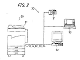
- Fig. 2 is a schematic diagram showing a configuration of a network 30 including the image forming apparatus 20.
- Fig. 3 is a plan view showing an original 52 on which an image targeted for processing 51 including a target image portion 50 is recorded.
- the image processing apparatus 10 judges that the target image portion 50 is present in the image targeted for processing 51, which is an image read out by a color scanner 21; or an image taken by a digital camera 31; or an image obtained through a computer network, such as the Internet, and stored in a personal computer (hereafter abbreviated as "PC") 32 or a notebook-type personal computer (hereafter abbreviated as "note PC”) 33, the image targeted for processing 51 is no longer subjected to image formation. This makes it possible to prevent banknotes or valuable securities from being counterfeited and prevent confidential documents from being illicitly copied.
- PC personal computer
- note PC notebook-type personal computer
- the image forming apparatus 20 is composed of the image processing apparatus 10; the color scanner 21; a formed-image processing unit (hereafter referred to as "ICU") 22; a printer control unit (hereafter abbreviated as "PCU”) 23; and a color printer 24.
- ICU formed-image processing unit
- PCU printer control unit
- the color scanner 21 acts as reading means for reading out an original 52 on which an image such as the image targeted for processing 51 is recorded.
- the image targeted for processing 51 is read out and digitized as follows. Firstly, light is applied to the original 52. Then, the light reflected from the original 52 is converted into an electric signal while displacing a scanner head (not shown), which includes a plurality of photoelectric conversion elements ("CCD" for short) arranged in a main scanning direction A defined as a first direction, in a sub scanning direction B defined as a second direction that is perpendicular to the main scanning direction A.
- CCD photoelectric conversion elements
- the read image targeted for processing 51 is fed to the image processing apparatus 10 and the ICU 22, as well as to the PC 32 and the note PC 33 connected through the network 30 to the image forming apparatus 20.
- the color scanner 21 is operated in the main and sub scanning directions A and B at an optical resolution of 600 dpi, and outputs a 256-step gradation for each three primary colors of RGB, with the total number of available colors being 16,777,216.
- a predetermined treatment such as color correction so as to be suitably formed on a recording paper sheet by the color printer 24.
- the image having undergone such a treatment is fed to the color printer 24.
- the image processing apparatus 10 is composed of a pre-processing section 11, an image judging section 12, an image confirming section 13, and a storage section 14. In the image processing apparatus 10, the to-be-extracted target image portion 50 included in the image targeted for processing 51 is extracted.
- the image targeted for processing 51 which has been fed from the color scanner 21, as well as the digital camera 31, PC 32, and note PC 33 connected through the network 30 to the image forming apparatus 20, is converted into for example such an image as to have a resolution in a range approximately from 100 to 200 dpi, and two gradation levels (e.g. white and black colors) on the basis of a predetermined threshold value.
- the image targeted for processing 51 thus converted is fed to the image judging section 12. In this way, the image targeted for processing 51, which is used for image formation performed in the color printer 24, is converted into a low-volume image information used for extracting the target image portion 50.
- the image judging section 12 acting as judging means, judges whether or not a specific image part 53 constituting part of the target image portion 50 is included in the image targeted for processing 51.
- the image confirming section 13 acting as confirming means, when the image judging section 12 judges that the specific image part 53 is included in the image targeted for processing 51, whether or not a potential target image portion including the specific image part 53 is equal to the target image portion 50 is checked.
- the storage section 14 stores the target image portion 50, the image targeted for processing 51 having been converted by the pre-processing section 11, the specific image part 53 constituting part of the target image portion 50, etc.
- the PCU 23 controls the color printer 24 in such a manner that the image targeted for processing 51 having undergone a predetermined treatment in the ICU is prevented from being formed on a recording paper sheet.
- the color printer 24 may be so controlled that the image targeted for processing 51 fed from the ICU 22 is reproduced with noise added thereto.
- the PCU 23 controls the color printer 24 in such a manner that the image targeted for processing 51 having undergone a predetermined treatment in the ICU is formed on a recording paper sheet.
- the color printer 24 reproduces the image targeted for processing 51 fed from the ICU 22 on a recording paper sheet under the control of the PCU.
- the color printer 24 is realized by the use of for example image forming means for forming an image on a recording paper sheet by ejecting ink of plural colors from nozzles, such as an ink-jet type printer or an electrophotographic printer.
- Fig. 4A is a plan view showing the target image portion 50 and a template 54
- Fig. 48 is a plan view showing a potential target image portion 55 and a judging window 56
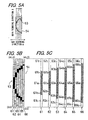
- Fig. 5A is a plan view showing the template 54, the main scanning direction A, and the sub scanning direction B
- Fig. 5B is an enlarged plan view showing the template 54
- Fig. 5C is a plan view showing individual regions constituting each pixel line of the template 54.
- the template 54 which has information on the specific image part 53 constituting part of the target image portion 50, is stored in the storage section 14, and is used for judging whether or not the specific image part 53 is included in the image targeted for processing 51.
- the image judging section 12 judges whether or not the specific image part 53 constituting part of the target image portion 50 is included in the image targeted for processing 51.
- the target image portion 50 is a specific image represented as a feature of the banknote.
- the original 52 is a confidential document as shown in Fig. 3
- the target image portion 50 is a seal represented as a circled kanji character " ".
- the image targeted for processing 51 carried on the original 52, which has been read out by the color scanner 21, is converted by the pre-processing section 11 into such an image as to have a resolution of 200 dpi and two gradation levels, i.e. two colors of white and black, and is thereafter fed to the image judging section 12.
- the specific image part 53 is the most distinctive part of the target image portion 50.
- the specific image part 53a is defined by a circular arc constituting part of a circumference of a circle representing the target image portion 50.
- the circle representing the target image portion 50 has a radius of n [mm].
- the circular arc is easily supposed to be part of the circle having a radius of n [mm].
- the potential target image portion 55 includes such an circular arc, it is supposed to be a circle having a radius of n [mm]. Thereupon, it is judged that the potential target image portion 55 is possibly equal to the target image portion 50.
- the template 54 for representing the specific image part 53 constituting part of the target image portion 50 is stored in advance.
- the template 54 has the same resolution and gradation level as those of the image targeted for processing 51 having been converted by the pre-processing section 11.
- the template 54 includes a pixel group obtained by arranging two or more pixel lines, in this embodiment, 6 pieces of pixel lines side by side in the sub scanning direction B.
- the pixel line consists of an array of a plurality of pixels, in this embodiment, 252 pieces of black and white pixels arranged in the main scanning direction A.
- the specific image part 53 is represented.
- the judging window 56 has a pixel group whose arrangement is substantially the same as in the template 54.
- the template 54 consists of a first pixel line 61; a second pixel line 62; a third pixel line 63; a fourth pixel line 64; a fifth pixel line 65; and a sixth pixel line 66.
- These pixel lines each of which includes 42 pieces of pixels arranged in the main scanning direction A, are arranged side by side in the sub scanning direction B.
- the judging window 56 consists of a first pixel line; a second pixel line; a third pixel line; a fourth pixel line; a fifth pixel line; and a sixth pixel line that correspond to the first to sixth pixel lines 61 to 66 of the template 54, respectively.
- the first to sixth pixel lines 61 to 66 of the template 54 are, in accordance with the arrangement status of their black pixels, each divided into several regions of three types including a plurality of pixels: a first region (61a to 66a); a second region (61b to 66b); and a third region (61c to 66c).
- the range of the number of black pixels to be included in the region is determined region by region.
- the range of black-pixel number is determined as follows.
- the first region 61a lies on the circular arc defining the specific image part 53.
- the number of black pixels is set in a wide range.
- the third region 61c is located at a sufficient distance from the circular arc. In this region, the number of black pixels is set in a range close to zero.
- the second region 61b is located in the vicinity of the circular arc. In this region, the number of black pixels is set in a range narrower than in the first region 61a.
- the image judging section 12 is operated as follows. Firstly, the image targeted for processing 51, which has been read out by the color scanner 21 and converted by the pre-processing section 11, is scanned pixel by pixel by the judging window 56 being moved in the main scanning direction A. Upon completion of the scanning in the main scanning direction A, the judging window 56 is moved in the sub scanning direction B on a pixel-by-pixel basis, and subsequently moved in the main scanning direction A once again. By repeating such a movement of the judging window 56 a given number of times, the entire image targeted for processing 51 is scanned. During this operation, comparison is made between the number of pixels of specific color within each region of the judging window 56 and that within each region of the template 54. According to the comparison results, whether or not the specific image part 53 is included in the image targeted for processing 51 is judged.
- the first pixel line of the judging window 56 is divided into several regions: a first region; a second region; and a third region, basically in the same manner as in the corresponding first pixel line 54a of the template 54. Then, judgment is made on whether or not the black-pixel numbers of the first to third regions of the first pixel line of the judging window 56 respectively fall in the ranges of the corresponding black-pixel numbers of the first to third regions 61a to 61c of the first pixel line 61 of the template 54, as listed in Table 1.
- the image judging section 12 similarly, judgment is made on whether or not the black-pixel numbers of the first to third regions of each of the second to sixth pixel lines of the judging window 56 respectively fall in the ranges of the corresponding black-pixel of the first to third regions of each of the second to sixth pixel lines 62 to 66 of the template 54, as listed in Table 1. In this way, when the black-pixel numbers of the first to third regions of each of the first to sixth pixel lines of the judging window 56 respectively fall in the ranges of the corresponding black-pixel numbers listed in Table 1, the image judging section 12 judges that the specific image part 53 is included in the image targeted for processing 51.
- the image judging section 12 judges that the specific image part 53 is included in the image targeted for processing 51 when the black-pixel numbers of the individual regions of each pixel line of the judging window 56 are each kept in a predetermined range.
- the image judging section 12 judges that the specific image part 53 is included in the image targeted for processing 51 when the black-pixel numbers of the individual regions of each pixel line of the judging window 56 are each kept in a predetermined range.
- the image judging section 12 since upper and lower limits are set on the number of black pixels within each of the divided regions of the pixel line, speedup can be achieved in the judgment operation. Moreover, since the image targeted for processing 51 is scanned using the judging window 56, as compared with the case where the image targeted for processing 51 as a whole is scanned at one time, the number of pixels required for onetime judging operation can be reduced, whereby making it possible to achieve speedup in the judgment operation. Further, as compared with the case where the image targeted for processing 51 is scanned on the basis of the individual pixels within the targeted for processing 51, judgment is made by performing scanning in consideration of the relationship between adjacent pixels. As a result, the judgment accuracy can be enhanced.
- the image judging section 12 judges that the specific image part 53 is included in the image targeted for processing 51, as shown in Fig. 4B, the potential target image portion 55 including a circular arc defining the specific image part 53 is created. At this time, the potential target image portion 55 assumes a circular shape.
- Fig. 6 is a plan view showing the target image portion 50 divided into a plurality of regions.
- the image confirming section 13 checks whether or not the potential target image portion 55 including the specific image part 53 is equal to the target image portion 50.
- the target image portion 50 is divided into four regions: a first divided region 71; a second divided region 72; a third divided region 73; and a fourth divided region 74, by circumferences of three different-size circles having their centers at a common position, i.e. the center of the circle representing the target image portion 50.
- the storage section 14 of the image processing apparatus 10 stores the range of the number of black pixels included in each of the divided regions 71 to 74.
- the potential target image portion 55 is, alike to the target image portion 50 shown in Fig. 6A, divided into four regions: first through fourth divided regions by circumferences of three different-size circles having their centers at a common position, i.e. the center of the circle representing the potential target image portion 55. Then, judgment is made on whether or not the number of black pixels within the first divided region of the potential target image portion 55 falls within the range of black-pixel number set for the first divided region 71 of the target image portion 50 listed in Table 2.
- the image confirming section 13 judges whether or not the number of black pixels within each of the second to fourth divided regions of the potential target image portion 55 respectively falls within the range of black-pixel number set for each of the second to fourth divided regions 72 to 74 of the target image portion 50 listed in Table 2.
- the image confirming section confirms that the potential target image portion 55 is equal to the target image portion 50. In this way, the image processing apparatus 10 extracts the target image portion 50 from the image targeted for processing 51.
- the target image portion 50 may be divided into four regions: a first divided region 71A; a second divided region 72A; a third divided region 73A; and a fourth divided region 74A, by two line segments intersecting at the center of the circle representing the target image portion 50, in such a way that the numbers of black pixels of the individual divided regions are averaged, namely, are set to be substantially the same.
- the range of black-pixel number for each of the divided regions 71A to 74A is set as listed in Table 3.
- the image judging section 12 judges whether or not the target image portion 50 is included in the image targeted for processing 51 by judging whether or not the specific image part 53 is included in the image targeted for processing 51.
- Such a judgment process requires less information than the case where whether or not the target image portion 50 is included in the image targeted for processing 51 is judged on the basis of the entire target image portion 50.
- judgment on the possibility that the target image portion 50 may be included in the image targeted for processing 51 can be made swiftly.
- the circuit configuration for performing such a judgment operation can be simplified, and also the capacity of the storage section 14 for storing information can be reduced.
- the image judging section 12 judges that the specific image part 53 is included in the image targeted for processing 51, whether or not the potential target image portion 55 including the specific image part 53 is equal to the target image portion 50 is checked. This allows the image processing apparatus 10 to extract the target image portion 50 with high accuracy.
- the target image portion 50 refers to a seal represented as a circled kanji character " " as shown in Fig. 4A.
- the target image portion is not limited thereto, but may be of an image described hereinbelow.
- Figs. 7A through 7D are plan views showing a square-shaped target image portion 80 and a square-shaped potential target image portion 85.
- a specific image part 53A is a substantially U-shaped image consisting of one side of the target image portion 80; part of another side continuous with said one side; and part of still another side continuous with said one side.
- the image judging section 12 employs a template 54A (refer to Fig. 7A) having a pixel group representing such a specific image part 53A, and a judging window 56A (refer to Fig. 7B) having a pixel group whose arrangement is substantially the same as in the template 54A.
- a template 54A (refer to Fig. 7A) having a pixel group representing such a specific image part 53A
- a judging window 56A (refer to Fig. 7B) having a pixel group whose arrangement is substantially the same as in the template 54A.
- the target image portion 80 is divided into four regions: a first divided region 81; a second divided region 82; a third divided region 83; and a fourth divided region 84, by four-side perimeters of three squares having their centers at a common position, i.e. the center of the square representing the target image portion 80.
- the number of black pixels is set in a predetermined range, and the resultant data on the pixel number is stored in the storage section 14 of the image processing apparatus 10.
- the target image portion 80 may be divided into four regions: a first divided region 81A; a second divided region 82A; a third divided region 83A; and a fourth divided region 84A, by two line segments: a line parallel to the one side of the target image portion 80; and a line perpendicular to the one side that intersect at the center of the target image portion 80.
- Figs. 8A through 8D are plan views showing a target image portion 90 and a potential target image portion 95, both of which have an isosceles right triangle shape.
- a specific image part 53B is a substantially L-shaped image consisting of part of the target image portion 90 including two perpendicular sides thereof.
- the image judging section 12 employs a template 54B (refer to Fig. 8A) having a pixel group representing such a specific image part 53B, and a judging window 56B (refer to Fig. 8B) having a pixel group whose arrangement is substantially the same as in the template 54B.
- the image judging section 12 by scanning the image targeted for processing 51 using the judging window 56B, whether or not the specific image part 53B is included in the image targeted for processing 51 is judged.
- the target image portion 90 is divided into four regions: a first divided region 91; a second divided region 92; a third divided region 93; and a fourth divided region 94, by three-side perimeters of three isosceles right triangles having their centers at a common position, i.e. the center of the isosceles right triangle representing the target image portion 90.
- the number of black pixels is set in a predetermined range, and the resultant data on the pixel number is stored in the storage section 14 of the image processing apparatus 10.
- the target image portion 90 may be divided into four regions: a first divided region 91A; a second divided region 92A; a third divided region 93A; and a fourth divided region 94A, each of which is shaped like an isosceles right triangle having a longer side whose dimension is half that of the longer side of the target image portion 90.
Landscapes
- Engineering & Computer Science (AREA)
- Physics & Mathematics (AREA)
- General Physics & Mathematics (AREA)
- Multimedia (AREA)
- Theoretical Computer Science (AREA)
- Image Analysis (AREA)
- Facsimile Image Signal Circuits (AREA)
- Image Processing (AREA)
- Cleaning In Electrography (AREA)
Abstract
Description

| Range of pixel number | |||||||||
| | | | | | | ||||
| 9 ≦ | First Region | 62a black ≦ 1 | | | | | |||
| black ≦ 2 | 3 ≦ | Second Region | 63b 3 ≦ | | 1 ≦ | | 2 ≦ | | 1 ≦ |
| Third Region | |||||||||
| 61c black ≦ 1 | | | | | |


Claims (7)
- An image processing apparatus for extracting a to-be-extracted target image portion (50, 80, 90) included in an image targeted for processing (51), comprising:judging means (12) for judging whether or not a specific image part (53, 53A, 53B) belonging to the target image portion (50, 80, 90) is included in the image targeted for processing (51); andconfirming means (13) for checking, when the specific image part (53, 53A, 53B) is judged to be included in the image targeted for processing (51), whether or not a potential target image portion (55, 85, 95) including the specific image part (53, 53A, 53B) is equal to the target image portion (50, 80, 90).
- The image processing apparatus of claim 1,
wherein the judging means (12) judges whether or not the specific image part (53, 53A, 53B) is included in the image targeted for processing (51) by comparing a number of pixels of specific color within part of the image targeted for processing (51) with a number of pixels of specific color within the specific image part (53, 53A, 53B). - The image processing apparatus of claim 1 or 2,
wherein the confirming means (13) checks whether or not a potential target image portion (55, 85, 95) is equal to the target image portion (50, 80, 90) by, after the potential target image portion (55, 85, 95) included in the image targeted for processing (51) and the target image portion (50, 80, 90) are respectively divided into a plurality of regions, comparing a number of pixels of specific color within each region of the potential target image portion (55, 85, 95) with a number of pixels of specific color within each region (71-74, 71A-74A, 81-84, 81A-84A, 91-94, 91A-94A) of the target image portion (50, 80, 90). - The image processing apparatus of claim 3,
wherein the target image portion (50, 80, 90) is divided in such a way that the numbers of pixels of specific color within the divided regions (71A-74A, 81A-84A, 91A-94A) are averaged. - The image processing apparatus any one of claims 1 to 4,
wherein the judging means (12) employs a template (54, 54A, 54B) for representing the specific image part (53, 53A, 53B) based on information on each pixel constituting a pixel group, the pixel group being obtained by arranging two or more pixel lines (61-66), each of which consists of an array of a plurality of pixels arranged in a predetermined first direction, in a second direction perpendicular to the first direction,
and wherein the judging means (12) judges whether or not the specific image part (53, 53A, 53B) is included in the image targeted for processing (51) by scanning the image targeted for processing (51) using a judging window (56, 56A, 56B) having a pixel group whose arrangement is substantially the same as in the template (54, 54A, 54B), followed by, after dividing each pixel line (61-66) into a plurality of regions (61a-66a, 61b-66b, 61c-66c) comparing a number of pixels of specific color within each of the regions of the judging window (56, 56A, 56B) with a number of pixels within each of the regions of the template (54, 54A, 54B). - The image processing apparatus of claim 5,
wherein the judging means (12) judges that the specific image part (53, 53A, 53B) is included in the image targeted for processing (51) when the number of pixels of specific color within each divided region (61a-66a, 61b-66b, 61c-66c) of the pixel line (61-66) is found to fall within a predetermined range. - The image processing apparatus any one of claims 1 to 6, wherein the apparatus is mounted in an image forming apparatus, further comprising:a pre-processing means (11) for converting information for use in image formation into low-volume information for use in image extraction.
Applications Claiming Priority (2)
| Application Number | Priority Date | Filing Date | Title |
|---|---|---|---|
| JP2001288830 | 2001-09-21 | ||
| JP2001288830A JP2003099788A (en) | 2001-09-21 | 2001-09-21 | Image processing device |
Publications (3)
| Publication Number | Publication Date |
|---|---|
| EP1296513A2 true EP1296513A2 (en) | 2003-03-26 |
| EP1296513A3 EP1296513A3 (en) | 2005-01-19 |
| EP1296513B1 EP1296513B1 (en) | 2012-11-14 |
Family
ID=19111408
Family Applications (1)
| Application Number | Title | Priority Date | Filing Date |
|---|---|---|---|
| EP02021353A Expired - Lifetime EP1296513B1 (en) | 2001-09-21 | 2002-09-23 | Image processing apparatus |
Country Status (4)
| Country | Link |
|---|---|
| US (1) | US7139438B2 (en) |
| EP (1) | EP1296513B1 (en) |
| JP (1) | JP2003099788A (en) |
| CN (1) | CN1170253C (en) |
Cited By (1)
| Publication number | Priority date | Publication date | Assignee | Title |
|---|---|---|---|---|
| EP4440096A1 (en) * | 2023-03-29 | 2024-10-02 | Zhuhai Pantum Electronics Co., Ltd. | Image source determination method and apparatus thereof, electronic device, and storage medium |
Families Citing this family (16)
| Publication number | Priority date | Publication date | Assignee | Title |
|---|---|---|---|---|
| TWI240067B (en) * | 2004-04-06 | 2005-09-21 | Sunplus Technology Co Ltd | Rapid color recognition method |
| JP4020908B2 (en) * | 2004-11-12 | 2007-12-12 | シャープ株式会社 | Image recording device |
| JP2006148578A (en) | 2004-11-19 | 2006-06-08 | Sharp Corp | Image processing apparatus, image reading apparatus, and image recording apparatus |
| JP4115490B2 (en) * | 2006-03-02 | 2008-07-09 | シャープ株式会社 | Method for assigning specific image information and image forming apparatus |
| JP4323506B2 (en) | 2006-10-23 | 2009-09-02 | シャープ株式会社 | Image processing device |
| JP4844427B2 (en) * | 2007-02-23 | 2011-12-28 | コニカミノルタビジネステクノロジーズ株式会社 | Image forming apparatus, specific document determination method, and specific document determination program |
| US8045798B2 (en) * | 2007-08-30 | 2011-10-25 | Xerox Corporation | Features generation and spotting methods and systems using same |
| JP4995751B2 (en) * | 2008-02-12 | 2012-08-08 | 株式会社リコー | Image processing apparatus, control method therefor, and ASIC apparatus |
| KR100961514B1 (en) * | 2008-06-16 | 2010-06-07 | 삼성전기주식회사 | Image data processing method and recording medium |
| KR100955949B1 (en) * | 2008-07-01 | 2010-05-03 | 삼성전기주식회사 | Image data processing method and recording medium |
| KR100958159B1 (en) * | 2008-07-01 | 2010-05-18 | 삼성전기주식회사 | Image data processing method and recording medium |
| JP4762327B2 (en) | 2009-03-24 | 2011-08-31 | シャープ株式会社 | Image processing apparatus and image forming apparatus |
| JP5948866B2 (en) * | 2011-12-27 | 2016-07-06 | 富士ゼロックス株式会社 | Image processing apparatus and program |
| BR102013029648B1 (en) * | 2013-11-18 | 2022-06-28 | Valid Soluções E Serviços De Segurança Em Meios De Pagamento E Identificação S.A. | PROCESS AND SYSTEM FOR IDENTIFICATION AND TRACKING OF PRODUCTS OF A PRODUCTION LINE |
| CN104484665A (en) * | 2014-12-05 | 2015-04-01 | 华东理工大学 | Image foreground extracting method based on Gaussian variation model |
| KR20180126794A (en) * | 2017-05-18 | 2018-11-28 | 에이치피프린팅코리아 유한회사 | Method for controlling image forming apparatus and image forming apparatus using thereof |
Family Cites Families (14)
| Publication number | Priority date | Publication date | Assignee | Title |
|---|---|---|---|---|
| FR2637144B1 (en) | 1988-09-23 | 1990-12-21 | France Etat | SHAPE RECOGNITION METHOD AND DEVICE FOR BINARIZED IMAGES |
| ATE215247T1 (en) * | 1990-06-22 | 2002-04-15 | Canon Kk | IMAGE PROCESSING DEVICE |
| JP3060131B2 (en) | 1991-09-26 | 2000-07-10 | 株式会社ゼクセル | Cooling control device for automotive air conditioner |
| US5515451A (en) * | 1992-01-08 | 1996-05-07 | Fuji Xerox Co., Ltd. | Image processing system for selectively reproducing documents |
| JP3242971B2 (en) * | 1992-02-27 | 2001-12-25 | キヤノン株式会社 | Image processing apparatus and method |
| JPH05244414A (en) * | 1992-02-28 | 1993-09-21 | Canon Inc | Picture processor |
| JP2606064B2 (en) | 1992-04-21 | 1997-04-30 | 富士ゼロックス株式会社 | Image processing device |
| US5533144A (en) | 1994-10-17 | 1996-07-02 | Xerox Corporation | Anti-counterfeit pattern detector and method |
| JP3178305B2 (en) * | 1995-06-29 | 2001-06-18 | オムロン株式会社 | Image processing method and apparatus, copier, scanner and printer equipped with the same |
| US5844991A (en) * | 1995-08-07 | 1998-12-01 | The Regents Of The University Of California | Script identification from images using cluster-based templates |
| JPH09274660A (en) | 1996-04-05 | 1997-10-21 | Omron Corp | Image recognition method and device, copier and scanner equipped with the same |
| US5999636A (en) * | 1997-10-10 | 1999-12-07 | Printprobe Technology, Llc | Apparatus and process for inspecting print material |
| US6067374A (en) | 1997-11-13 | 2000-05-23 | Xerox Corporation | Seal detection system and method |
| US6553136B1 (en) | 1999-10-28 | 2003-04-22 | Hewlett-Packard Company | System and method for counterfeit protection |
-
2001
- 2001-09-21 JP JP2001288830A patent/JP2003099788A/en active Pending
-
2002
- 2002-09-20 US US10/251,429 patent/US7139438B2/en not_active Expired - Lifetime
- 2002-09-21 CN CNB021482098A patent/CN1170253C/en not_active Expired - Fee Related
- 2002-09-23 EP EP02021353A patent/EP1296513B1/en not_active Expired - Lifetime
Non-Patent Citations (1)
| Title |
|---|
| None |
Cited By (1)
| Publication number | Priority date | Publication date | Assignee | Title |
|---|---|---|---|---|
| EP4440096A1 (en) * | 2023-03-29 | 2024-10-02 | Zhuhai Pantum Electronics Co., Ltd. | Image source determination method and apparatus thereof, electronic device, and storage medium |
Also Published As
| Publication number | Publication date |
|---|---|
| US7139438B2 (en) | 2006-11-21 |
| CN1410942A (en) | 2003-04-16 |
| CN1170253C (en) | 2004-10-06 |
| US20030099394A1 (en) | 2003-05-29 |
| JP2003099788A (en) | 2003-04-04 |
| EP1296513B1 (en) | 2012-11-14 |
| EP1296513A3 (en) | 2005-01-19 |
Similar Documents
| Publication | Publication Date | Title |
|---|---|---|
| EP1296513B1 (en) | Image processing apparatus | |
| JP3178305B2 (en) | Image processing method and apparatus, copier, scanner and printer equipped with the same | |
| EP0800123B1 (en) | Image recognition method and device and copier and scanner employing same | |
| US7209599B2 (en) | System and method for scanned image bleedthrough processing | |
| US6542629B1 (en) | Digital imaging method and apparatus for detection of document security marks | |
| JP3392798B2 (en) | Image attribute determination method and apparatus | |
| US6801636B2 (en) | Image processing apparatus and method, and storage medium | |
| US6014453A (en) | Counterfeit detecting method and device to generate counterfeit probability data and apparatus employing same | |
| CN101388073A (en) | Image checking device, image checking method, and image data output processing device | |
| US20110194729A1 (en) | Apparatus and method for image processing of ground pattern | |
| US7720290B2 (en) | Method, program, and apparatus for detecting specific information included in image data of original image, and computer-readable storing medium storing the program | |
| CN101753764A (en) | Image processing apparatus and method, image reading apparatus, and image sending method | |
| EP1755327B1 (en) | Detection of document security marks using run profiles | |
| JP4745476B2 (en) | Mark detection apparatus and control method thereof | |
| US20110170133A1 (en) | Image forming apparatus, method of forming image and method of authenticating document | |
| US20020051157A1 (en) | Image processing method and apparatus for detecting characteristic points | |
| JPH06133159A (en) | Image processing device | |
| US7379210B2 (en) | Image processing apparatus, image forming apparatus, and image processing method | |
| JP2899736B2 (en) | Image processing apparatus and copying machine using the same | |
| JP3178440B2 (en) | Image processing method and apparatus, copier, scanner and printer equipped with the same | |
| US8358848B2 (en) | Image recognition device, copy apparatus and image recognition method | |
| JPH09120456A (en) | Image processing method and apparatus, copier, printer and scanner using the same | |
| JP3178439B2 (en) | Image processing method and apparatus, copier, scanner and printer equipped with the same | |
| JP3587008B2 (en) | Image input device | |
| JP4758402B2 (en) | Image forming apparatus |
Legal Events
| Date | Code | Title | Description |
|---|---|---|---|
| PUAI | Public reference made under article 153(3) epc to a published international application that has entered the european phase |
Free format text: ORIGINAL CODE: 0009012 |
|
| AK | Designated contracting states |
Kind code of ref document: A2 Designated state(s): AT BE BG CH CY CZ DE DK EE ES FI FR GB GR IE IT LI LU MC NL PT SE SK TR |
|
| AX | Request for extension of the european patent |
Extension state: AL LT LV MK RO SI |
|
| PUAL | Search report despatched |
Free format text: ORIGINAL CODE: 0009013 |
|
| AK | Designated contracting states |
Kind code of ref document: A3 Designated state(s): AT BE BG CH CY CZ DE DK EE ES FI FR GB GR IE IT LI LU MC NL PT SE SK TR |
|
| AX | Request for extension of the european patent |
Extension state: AL LT LV MK RO SI |
|
| 17P | Request for examination filed |
Effective date: 20050513 |
|
| AKX | Designation fees paid |
Designated state(s): DE FR GB |
|
| RIC1 | Information provided on ipc code assigned before grant |
Ipc: H04N 1/56 20060101AFI20120315BHEP |
|
| GRAP | Despatch of communication of intention to grant a patent |
Free format text: ORIGINAL CODE: EPIDOSNIGR1 |
|
| GRAS | Grant fee paid |
Free format text: ORIGINAL CODE: EPIDOSNIGR3 |
|
| GRAA | (expected) grant |
Free format text: ORIGINAL CODE: 0009210 |
|
| AK | Designated contracting states |
Kind code of ref document: B1 Designated state(s): DE FR GB |
|
| REG | Reference to a national code |
Ref country code: GB Ref legal event code: FG4D |
|
| REG | Reference to a national code |
Ref country code: DE Ref legal event code: R096 Ref document number: 60244024 Country of ref document: DE Effective date: 20130110 |
|
| PLBE | No opposition filed within time limit |
Free format text: ORIGINAL CODE: 0009261 |
|
| STAA | Information on the status of an ep patent application or granted ep patent |
Free format text: STATUS: NO OPPOSITION FILED WITHIN TIME LIMIT |
|
| 26N | No opposition filed |
Effective date: 20130815 |
|
| REG | Reference to a national code |
Ref country code: DE Ref legal event code: R097 Ref document number: 60244024 Country of ref document: DE Effective date: 20130815 |
|
| REG | Reference to a national code |
Ref country code: FR Ref legal event code: PLFP Year of fee payment: 15 |
|
| REG | Reference to a national code |
Ref country code: FR Ref legal event code: PLFP Year of fee payment: 16 |
|
| REG | Reference to a national code |
Ref country code: FR Ref legal event code: PLFP Year of fee payment: 17 |
|
| PGFP | Annual fee paid to national office [announced via postgrant information from national office to epo] |
Ref country code: DE Payment date: 20190918 Year of fee payment: 18 Ref country code: FR Payment date: 20190925 Year of fee payment: 18 |
|
| PGFP | Annual fee paid to national office [announced via postgrant information from national office to epo] |
Ref country code: GB Payment date: 20190920 Year of fee payment: 18 |
|
| REG | Reference to a national code |
Ref country code: DE Ref legal event code: R119 Ref document number: 60244024 Country of ref document: DE |
|
| GBPC | Gb: european patent ceased through non-payment of renewal fee |
Effective date: 20200923 |
|
| PG25 | Lapsed in a contracting state [announced via postgrant information from national office to epo] |
Ref country code: DE Free format text: LAPSE BECAUSE OF NON-PAYMENT OF DUE FEES Effective date: 20210401 Ref country code: FR Free format text: LAPSE BECAUSE OF NON-PAYMENT OF DUE FEES Effective date: 20200930 |
|
| PG25 | Lapsed in a contracting state [announced via postgrant information from national office to epo] |
Ref country code: GB Free format text: LAPSE BECAUSE OF NON-PAYMENT OF DUE FEES Effective date: 20200923 |