EP1296462A1 - Radio reception apparatus and radio reception method - Google Patents
Radio reception apparatus and radio reception method Download PDFInfo
- Publication number
- EP1296462A1 EP1296462A1 EP02774065A EP02774065A EP1296462A1 EP 1296462 A1 EP1296462 A1 EP 1296462A1 EP 02774065 A EP02774065 A EP 02774065A EP 02774065 A EP02774065 A EP 02774065A EP 1296462 A1 EP1296462 A1 EP 1296462A1
- Authority
- EP
- European Patent Office
- Prior art keywords
- delay time
- delay
- rake combining
- section
- signal
- Prior art date
- Legal status (The legal status is an assumption and is not a legal conclusion. Google has not performed a legal analysis and makes no representation as to the accuracy of the status listed.)
- Granted
Links
Images



Classifications
-
- H—ELECTRICITY
- H04—ELECTRIC COMMUNICATION TECHNIQUE
- H04B—TRANSMISSION
- H04B1/00—Details of transmission systems, not covered by a single one of groups H04B3/00 - H04B13/00; Details of transmission systems not characterised by the medium used for transmission
- H04B1/69—Spread spectrum techniques
- H04B1/707—Spread spectrum techniques using direct sequence modulation
- H04B1/7097—Interference-related aspects
- H04B1/7103—Interference-related aspects the interference being multiple access interference
- H04B1/7105—Joint detection techniques, e.g. linear detectors
-
- H—ELECTRICITY
- H04—ELECTRIC COMMUNICATION TECHNIQUE
- H04B—TRANSMISSION
- H04B1/00—Details of transmission systems, not covered by a single one of groups H04B3/00 - H04B13/00; Details of transmission systems not characterised by the medium used for transmission
- H04B1/69—Spread spectrum techniques
- H04B1/707—Spread spectrum techniques using direct sequence modulation
- H04B1/7097—Interference-related aspects
- H04B1/711—Interference-related aspects the interference being multi-path interference
- H04B1/7113—Determination of path profile
-
- H—ELECTRICITY
- H04—ELECTRIC COMMUNICATION TECHNIQUE
- H04B—TRANSMISSION
- H04B1/00—Details of transmission systems, not covered by a single one of groups H04B3/00 - H04B13/00; Details of transmission systems not characterised by the medium used for transmission
- H04B1/69—Spread spectrum techniques
- H04B1/707—Spread spectrum techniques using direct sequence modulation
- H04B1/7097—Interference-related aspects
- H04B1/711—Interference-related aspects the interference being multi-path interference
- H04B1/7115—Constructive combining of multi-path signals, i.e. RAKE receivers
Definitions
- the present invention relates to a radio receiving apparatus and radio receiving method employed in a digital radio communication system.
- CDMA Code Division Multiple Access
- CDMA Code Division Multiple Access
- a radio signal is received in radio receiving section 52 via antenna 51.
- predetermined radio reception processing such as, down conversion, A/D conversion, etc.
- RAKE combining section 53 and correlation processing section 54 are performed on the received signal, and the signal being subjected to radio reception processing is outputted to RAKE combining section 53 and correlation processing section 54.
- correlation processing section 54 a correlation processing between a known signal (midamble) and the signal being subjected to radio reception processing is carried out.
- the signal after correlation processing (correlation result) is outputted to delay profile generating section 55.
- a delay profile is generated in delay profile generating section 55 based on the correlation result. This delay profile is outputted to RAKE combining section 53.
- RAKE combining section 53 RAKE combining is carried out based on the delay profile, and the result of RAKE combining is outputted to JD section 56. Joint detection processing is performed on the signal being subjected to RAKE combining in JD section 56 in accordance with maximum delay time. Receiving signals of all codes are outputted after the joint detection processing.
- the amount of calculations to generate the matrix A in the joint detection processing is given by (NQ+W-1) ⁇ (KN) assuming that N is the number of transmission symbols, Q is the spreading sequence, W is the delay time window (expressed in CDMA chip time unit), and K is the number of the transmitting multicode. Moreover, the amount of calculating the cross correlation A H A becomes KN ⁇ KN which is extremely large amount. In this case, the influence of the delay time window W is extremely large.
- the delay time window W is set to include the delay signal of maximum delay time.
- the delay time window W is set to include all the 3 paths in which
- Such a window is similar to the window used in RAKE combining.
- the inventors reach the present invention by focusing their attention on the existence of a plurality of delay waves that have small delay from the precedence signal and the existence of few delay waves which are largely separated from the precedence signal in radio communication under multipath environment, and reducing the calculation amount by cancelling peripheral multipath interferences of the precedence wave so that a sufficient performance is obtained.
- FIG. 2 is a block diagram showing a configuration of a radio receiving apparatus according to Embodiment 1 of the present invention
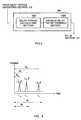
- FIG. 3 is a block diagram showing a configuration of a maximum delay time setting section included in radio receiving apparatus according to Embodiment 1 of the present invention.
- a radio signal is received in radio receiving section 102 via antenna 101.
- predetermined radio reception processing such as, down conversion, A/D conversion, etc.
- RAKE combining section 103 and correlation processing section 104 are performed on the received signal, and the signal being subjected to radio reception processing is outputted to RAKE combining section 103 and correlation processing section 104.
- correlation processing section 104 a correlation processing between a known signal (midamble) and the signal being subjected to radio reception processing is carried out.
- the signal after correlation processing (correlation result) is outputted to delay profile generating section 105.
- a delay profile is generated in delay profile generating section 105 based on the correlation result. This delay profile is outputted to RAKE combining section 103 and maximum delay time setting section 106.
- the range of a delay wave used for cancelling the interference is determined and the maximum delay time is set in maximum delay time setting section 106. This maximum delay time is outputted to JD section 107.
- RAKE combining section 103 RAKE combining is carried out based on the delay profile, and the RAKE combining result is outputted to JD section 107. According to the maximum delay time, joint detection processing is performed on the signal being subjected to RAKE combining in JD section 107. Receiving signals of all codes are outputted after this joint detection processing.
- a radio signal of a system in which interference cancellation is carried out by joint detection is composed of a known signal (midamble) used for estimating the delay profile and data signal.
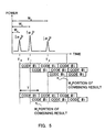
- the delay profile is expressed by the time ⁇ k of the channel estimation value of the power of ⁇ k which is given by
- FIG. 4 shows the case of 3 paths. That is to say, in the delay profile shown in FIG. 4, the path of time ⁇ 0 is shown by the channel estimation value of the power of ⁇ 0 which is given by
- the value W in FIG. 4 shows the window width including the delay wave of which the delay time serves as the maximum, and which is used as window width in RAKE combining.
- RAKE combining section 103 a despreading processing is performed on the signal after being subjected to radio reception processing using the same spreading code as the spreading code used by the transmission side apparatus, and the signal after such despreading processing (despreading signal) and the delay profile are employed to carry out RAKE combining.
- This RAKE combining is carried out when all multi-paths are included in the time period (window width) W.
- the result obtained by the RAKE combining is the receiving signal when the cross correlation between spreading codes is not cancelled.
- the result of the RAKE combining is shown by the vector b.
- a delay time width W' used for cancelling the interference is set using the delay profile.
- the delay spread is calculated and the delay time window of delay wave included in the delay spread is set as W'.
- the delay spread is calculated in delay spread calculating section 1061 of maximum delay time setting section 106. That is to say, the standard deviation of the delayprofile is calculated.
- the calculated delay spread is outputted to maximum delay time determining section 1062.
- the maximum delay time (window width) W' is determined in maximum delay time determining section 1062 based on the delay spread.
- the maximum delay time is set according to the delay spread, it is possible to set the maximum delay time that includes the delay waves which cause interference and are to be cancelled by JD., hence, it becomes possible to reduce the performance degradation by making the window width narrower than that of RAKE combining.
- the matrix A H A of the correlation matrix A is calculated in JD section 107.
- the calculation amount of the correlation A H A becomes (KN) ⁇ (KN) .
- the receiving signals of all codes can be obtained.
- FIG. 6 is a graph to explain the effect of a radio receiving apparatus according to Embodiment 1 of the present invention.
- the mark ⁇ (1) shows the case where both window width W used for RAKE combining and window width W' used for JD is 57
- the mark ⁇ (2) shows the case (present embodiment) where window width W used for RAKE combining is 57 while window width W' used for RAKE combining is 17,
- the mark ⁇ (3) shows the case where both window width W used for RAKE combining and window width W' used for JD is 17.
- a maximum performance can be obtained since all of the multi-paths are used in RAKE combining, and it is not only possible to carry out a sufficient cancellation of the interference caused due to cross correlations between spreading codes but it is also possible to reduce the calculation amount of JD while keeping the performance of RAKE combining because the window width is optimally set based on the delay spread.
- a maximum delay time is set by carrying out threshold value decision on the correlation value resulted from calculating the convolution of the delay profile of spreading codes, and the case when outputting receiving signal after performing interference cancellation using such a maximum delay time will be explained.
- FIG. 7 is a block diagram showing a configuration of maximum delay time setting section included in radio receiving apparatus according to Embodiment 2 of the present invention.
- maximum delay time setting section 106 comprises spreading code selecting section 1063 to select a set of spreading codes to be convoluted with delay profile, convolution calculating section 1064 to calculate cross correlation from the result of convolution calculation between the selected spreading codes and the delay profile, and threshold value deciding section 1065 to carry out threshold value decision as compared to cross correlation value resulted from convolution operation.
- radio receiving apparatus comprising the aforementioned configuration
- the operation of radio receiving apparatus comprising the aforementioned configuration will be explained below.
- RAKE combining section 103 despreading processing is performed on the signal after being subjected to radio reception processing using the same spreading code as the spreading code used by transmission side apparatus, both signal after such despreading processing (despreading signal) and delay profile are employed to carry out RAKE combining.
- This RAKE combining is carried out using all multi-paths which are included in the time period (window width) W.
- the result obtained by RAKE combining is the receiving signal when cross correlation between spreading codes is not cancelled.
- the result of RAKE combining is shown by the vector b.
- a delay time width W' used for cancelling the interference is set using delay profile.
- a threshold value decision as compared to correlation value result from convolution operation of spreading codes and delay profile is carried out, in other words, maximum delay time W' is set by carrying out threshold value decision as compared to cross correlation of spreading codes optionally chosen.
- spreading code selecting section 1063 the set of spreading codes to be used in convolution operation is selected, and this set of spreading codes is outputted to convolution calculating section 1064.
- Each of spreading codes and delay profile are subjected to convolution operation in convolution calculating section 1064.
- correlation is calculated from the results each spreading code and delay profile are convolution-operated. This correlation result is equivalent to cross correlation between spreading codes when there is a delay wave.
- window widths W k can be manipulated relating to cross correlation value.
- Convolution calculating section 1064 outputs the obtained cross correlation value to threshold value deciding section 1065.
- threshold value deciding section 1065 cross correlation values of several window width P (W k ) are compared to a previously set threshold value P th .
- W' which becomes smaller than this threshold value P th is acquired.
- a threshold value decision is performed on cross correlation value in threshold value deciding section 1065.
- window width of the interference cancellation (JD) is W1
- the difference of a real interference amount P (W) and the interference amount P (W 1 ) when the window width is W 1 becomes small. Therefore, when the window width is W 1 , it is possible to decide that there is no difference of the ability of interference cancellation when it was carried out in window width W. However, in such a case, window width W' of the interference cancellation (JD) is set to W 1 .
- the threshold value can be set appropriately to keep the performance deterioration in the range that does not affect the system by setting the window width smaller than that in the case of RAKE combining.
- window width is the maximum delay time W' which includes the paths of delay time ⁇ 0 and ⁇ 1 .
- the matrix A H A of the correlation matrix A is calculated in JD section 107.
- the calculation amount of the correlation operation A H A becomes (KN) ⁇ (KN) .
- the receiving signals of all codes are obtained.
- Embodiment 1 it is possible to show the same effect as that of Embodiment 1. That is, maximum performance can be drawn since all of the multi-paths are used in RAKE combining, and relating to JD, it is not only possible to carry out a sufficient cancellation of the interference due to cross correlations between spreading codes but it is also possible to reduce the calculation amount of JD while keeping the performance of RAKE combining because the window width is optimally set based on the delay spread.
- the present invention is not limited to the aforementioned embodiments 1 and 2, and various changes can be made without varying from the scope of the invention.
- the present invention can also be applied similarly when the number of paths is 2, 4 or more.
- the radio receiving apparatus and radio receiving method of the present invention can be applied to digital radio communication system, particularly to radio base station apparatus of CDMA system.
- the maximum performance can be drawn since all of the multi-paths are used in RAKE combining, and relating to JD, it is not only possible to carry out a sufficient cancellation of the interference due to cross correlations between spreading codes but it is also possible to reduce the calculation amount of JD while keeping the performance of RAKE combining because the window width is optimally set based on the delay spread.
- the present invention relates to a radio receiving apparatus and radio receiving method employed in a digital radio communication system.
Landscapes
- Engineering & Computer Science (AREA)
- Computer Networks & Wireless Communication (AREA)
- Signal Processing (AREA)
- Noise Elimination (AREA)
Abstract
Description
Claims (7)
- A radio receiving apparatus comprising:delay profile generating section to generate a delay profile using a known signal included in a receiving signal in which one or more user signals were code-multiplexed;RAKE combining section to set a first delay time in said delay profile and to carry out RAKE combining within the range of said first delay time; andinterference cancellation section to set a second delay time which is shorter than said first delay time in said delay profile, to carry out interference cancellation processing on the signal after being subjected to said RAKE combining within the range of said second delay time, and to output the receiving signals of all codes.
- The radio receiving apparatus according to claim 1, wherein said second delay time is determined by a delay spread obtained from said delay profile.
- The radio receiving apparatus according to claim 1, wherein said second delay time is set based on the value of cross correlation of spreading codes selected voluntarily.
- A radio base station apparatus comprising a radio receiving apparatus, wherein said radio receiving apparatus comprising:delay profile generating section to generate a delay profile using a known signal included in a receiving signal in which one or more user signals were code-multiplexed;RAKE combining section to set a first delay time in said delay profile and to carry out RAKE combining within the range of said first delay time; andinterference cancellation section to set a second delay time which is shorter than said first delay time in said delay profile, to carry out interference cancellation processing on the signal after being subjected to said RAKE combining within the range of said second delay time, and to output the receiving signals of all codes.
- A radio receiving method comprising:delay profile generating step which generates a delay profile using a known signal included in a receiving signal in which one or more user signals were code-multiplexed;RAKE combining step which sets a first delay time in said delay profile and carries out RAKE combining within the range of said first delay time; andinterference cancellation step which sets a second delay time that is shorter than said first delay time in said delay profile, carries out interference cancellation processing on the signal after being subjected to said RAKE combining within the range of said second delay time, and outputs the receiving signals of all codes.
- The radio receiving method according to claim 5, wherein said second delay time is determined by a delay spread obtained from said delay profile.
- The radio receiving method according to claim 5, wherein said second delay time is set based on the value of cross correlation of spreading codes selected voluntarily.
Applications Claiming Priority (3)
| Application Number | Priority Date | Filing Date | Title |
|---|---|---|---|
| JP2001156625 | 2001-05-25 | ||
| JP2001156625A JP3345406B1 (en) | 2001-05-25 | 2001-05-25 | Wireless receiving apparatus and wireless receiving method |
| PCT/JP2002/004902 WO2002098011A1 (en) | 2001-05-25 | 2002-05-21 | Radio reception apparatus and radio reception method |
Publications (3)
| Publication Number | Publication Date |
|---|---|
| EP1296462A1 true EP1296462A1 (en) | 2003-03-26 |
| EP1296462A4 EP1296462A4 (en) | 2003-07-23 |
| EP1296462B1 EP1296462B1 (en) | 2004-10-06 |
Family
ID=19000615
Family Applications (1)
| Application Number | Title | Priority Date | Filing Date |
|---|---|---|---|
| EP20020774065 Expired - Lifetime EP1296462B1 (en) | 2001-05-25 | 2002-05-21 | Radio reception apparatus and radio reception method |
Country Status (6)
| Country | Link |
|---|---|
| US (1) | US7167505B2 (en) |
| EP (1) | EP1296462B1 (en) |
| JP (1) | JP3345406B1 (en) |
| CN (1) | CN1198405C (en) |
| DE (1) | DE60201482T2 (en) |
| WO (1) | WO2002098011A1 (en) |
Cited By (3)
| Publication number | Priority date | Publication date | Assignee | Title |
|---|---|---|---|---|
| EP1641161A4 (en) * | 2003-08-05 | 2006-08-16 | Da Tang Mobile Comm Equipment | Method for detecting the orthogonal code cdma signal |
| US7400692B2 (en) | 2004-01-14 | 2008-07-15 | Interdigital Technology Corporation | Telescoping window based equalization |
| US7437135B2 (en) | 2003-10-30 | 2008-10-14 | Interdigital Technology Corporation | Joint channel equalizer interference canceller advanced receiver |
Families Citing this family (12)
| Publication number | Priority date | Publication date | Assignee | Title |
|---|---|---|---|---|
| JP3581356B2 (en) * | 2002-05-22 | 2004-10-27 | 松下電器産業株式会社 | Communication terminal apparatus and spreading code estimation method |
| CN1579050A (en) * | 2002-05-23 | 2005-02-09 | 松下电器产业株式会社 | Receiving device and receiving method |
| JP4259964B2 (en) * | 2003-09-12 | 2009-04-30 | 富士通株式会社 | Rake receiver with MIXR function |
| US20050254559A1 (en) * | 2004-05-11 | 2005-11-17 | Wen-Sheng Hou | Packet detection |
| US8442441B2 (en) * | 2004-12-23 | 2013-05-14 | Qualcomm Incorporated | Traffic interference cancellation |
| JP5024934B2 (en) * | 2005-01-17 | 2012-09-12 | シャープ株式会社 | Wireless communication device |
| KR100899302B1 (en) * | 2005-01-18 | 2009-05-27 | 가부시키가이샤 엔티티 도코모 | Mobile communication terminal, and multipath interference eliminating method |
| DE112006001114T5 (en) * | 2005-05-16 | 2008-04-30 | Murata Manufacturing Co. Ltd. | radar |
| JP4129014B2 (en) * | 2005-08-10 | 2008-07-30 | 株式会社エヌ・ティ・ティ・ドコモ | Mobile communication terminal |
| EP1775849A1 (en) * | 2005-10-14 | 2007-04-18 | Telefonaktiebolaget LM Ericsson (publ) | Method and arrangement for interference mitigation |
| US8396151B2 (en) * | 2006-10-19 | 2013-03-12 | Qualcomm Incorporated | Timing tracking in a multiple receive antenna system |
| US7894774B2 (en) * | 2007-08-02 | 2011-02-22 | Wireless Technology Solutions Llc | Communication unit and method for interference mitigation |
Family Cites Families (15)
| Publication number | Priority date | Publication date | Assignee | Title |
|---|---|---|---|---|
| US5490165A (en) * | 1993-10-28 | 1996-02-06 | Qualcomm Incorporated | Demodulation element assignment in a system capable of receiving multiple signals |
| IL120538A (en) * | 1997-03-26 | 2000-11-21 | Dspc Tech Ltd | Method and apparatus for reducing spread-spectrum noise |
| FI104020B1 (en) * | 1997-06-23 | 1999-10-29 | Nokia Telecommunications Oy | Reception procedure and recipients |
| JP3793632B2 (en) * | 1997-12-18 | 2006-07-05 | 松下電器産業株式会社 | Cell search method and mobile station apparatus |
| JPH11261440A (en) * | 1998-03-11 | 1999-09-24 | Oki Electric Ind Co Ltd | Receiver |
| DE19826036C2 (en) | 1998-06-12 | 2000-05-25 | Bosch Gmbh Robert | Method for separating several superimposed coded user signals |
| US6373882B1 (en) * | 1998-11-06 | 2002-04-16 | Telefonaktiebolaget Lm Ericsson (Publ) | Motion estimator for a CDMA mobile station |
| JP4029237B2 (en) * | 1998-11-26 | 2008-01-09 | ソニー株式会社 | Reception method and wireless communication terminal device |
| JP3320667B2 (en) * | 1998-12-21 | 2002-09-03 | 株式会社東芝 | Spread spectrum wireless communication equipment |
| JP2000261412A (en) | 1999-03-06 | 2000-09-22 | Matsushita Electric Ind Co Ltd | Interference signal canceller |
| JP3279297B2 (en) * | 1999-09-24 | 2002-04-30 | 日本電気株式会社 | Search method and receiving apparatus in CDMA mobile communication receiving system |
| JP3387471B2 (en) * | 2000-02-14 | 2003-03-17 | 日本電気株式会社 | Spread spectrum communication system receiver and path search method for spread spectrum communication |
| JP2001244849A (en) * | 2000-02-29 | 2001-09-07 | Matsushita Electric Ind Co Ltd | Communication terminal device and cell search method |
| JP3522678B2 (en) | 2000-09-27 | 2004-04-26 | 松下電器産業株式会社 | Communication terminal device and demodulation method |
| JP3440068B2 (en) | 2000-09-29 | 2003-08-25 | 松下電器産業株式会社 | Demodulation device and demodulation method |
-
2001
- 2001-05-25 JP JP2001156625A patent/JP3345406B1/en not_active Expired - Fee Related
-
2002
- 2002-05-21 DE DE2002601482 patent/DE60201482T2/en not_active Expired - Lifetime
- 2002-05-21 CN CNB028018354A patent/CN1198405C/en not_active Expired - Lifetime
- 2002-05-21 WO PCT/JP2002/004902 patent/WO2002098011A1/en not_active Ceased
- 2002-05-21 EP EP20020774065 patent/EP1296462B1/en not_active Expired - Lifetime
- 2002-05-21 US US10/332,144 patent/US7167505B2/en not_active Expired - Fee Related
Cited By (5)
| Publication number | Priority date | Publication date | Assignee | Title |
|---|---|---|---|---|
| EP1641161A4 (en) * | 2003-08-05 | 2006-08-16 | Da Tang Mobile Comm Equipment | Method for detecting the orthogonal code cdma signal |
| KR100722858B1 (en) | 2003-08-05 | 2007-05-30 | 다 탕 모바일 커뮤니케이션즈 이큅먼트 코포레이션 리미티드 | Method for Detecting the Orthogonal Code CDMA Signal |
| US7636384B2 (en) | 2003-08-05 | 2009-12-22 | Da Tang Mobile Communications Equipment Co., Ltd. | Method for detecting the orthogonal code CDMA signal |
| US7437135B2 (en) | 2003-10-30 | 2008-10-14 | Interdigital Technology Corporation | Joint channel equalizer interference canceller advanced receiver |
| US7400692B2 (en) | 2004-01-14 | 2008-07-15 | Interdigital Technology Corporation | Telescoping window based equalization |
Also Published As
| Publication number | Publication date |
|---|---|
| JP2002353853A (en) | 2002-12-06 |
| EP1296462A4 (en) | 2003-07-23 |
| CN1463503A (en) | 2003-12-24 |
| DE60201482T2 (en) | 2005-02-03 |
| US7167505B2 (en) | 2007-01-23 |
| WO2002098011A1 (en) | 2002-12-05 |
| JP3345406B1 (en) | 2002-11-18 |
| DE60201482D1 (en) | 2004-11-11 |
| US20030108091A1 (en) | 2003-06-12 |
| EP1296462B1 (en) | 2004-10-06 |
| CN1198405C (en) | 2005-04-20 |
Similar Documents
| Publication | Publication Date | Title |
|---|---|---|
| JP2924864B2 (en) | Adaptive rake reception method | |
| KR100684023B1 (en) | Method and apparatus for interference cancellation in rake receiver | |
| EP1235360A1 (en) | Communication terminal apparatus and demodulation method | |
| US7397842B2 (en) | Method and apparatus for combining weight computation in a DS-CDMA RAKE receiver | |
| US20040136445A1 (en) | Method and apparatus for interference suppression with efficient matrix inversion in a DS-CDMA system | |
| US7167505B2 (en) | Radio receiving apparatus and radio receiving method | |
| JP3159378B2 (en) | Spread spectrum communication system | |
| JP3275079B2 (en) | Method and apparatus for coherent channel estimation in a communication system | |
| US20020163896A1 (en) | Radio communication terminal and interference canceling method | |
| US7151792B2 (en) | Spread spectrum rake receiver | |
| WO2008069736A2 (en) | Multi-transmitter interference suppression using code-specific combining | |
| EP1605601B1 (en) | Interference eliminating apparatus and method | |
| US8295328B2 (en) | Doppler frequency control of G-rake receiver | |
| KR100383594B1 (en) | Method and apparatus for downlink joint detector in communication system | |
| JP3875998B2 (en) | Communication system apparatus and method | |
| EP1605602B1 (en) | Interference reduction apparatus and method | |
| US6996159B2 (en) | Reducing spread spectrum noise | |
| EP1299961A1 (en) | Receiver and method of receiving a cdma signal in presence of interferers with unknown spreading factors | |
| JP4774306B2 (en) | Interference reduction receiving apparatus and method | |
| JP3926366B2 (en) | Spread spectrum rake receiver | |
| JP2002280928A (en) | Spreading factor estimation system and method | |
| JP2001196968A (en) | Lake receiver | |
| JPH0795130A (en) | Spread spectrum signal receiver | |
| JP2005311914A (en) | Radio receiving apparatus and radio receiving method | |
| JP2002305471A (en) | Channel estimation device |
Legal Events
| Date | Code | Title | Description |
|---|---|---|---|
| PUAI | Public reference made under article 153(3) epc to a published international application that has entered the european phase |
Free format text: ORIGINAL CODE: 0009012 |
|
| 17P | Request for examination filed |
Effective date: 20030114 |
|
| AK | Designated contracting states |
Designated state(s): AT BE CH CY DE DK ES FI FR GB GR IE IT LI LU MC NL PT SE TR Kind code of ref document: A1 Designated state(s): AT BE CH CY DE DK ES FI FR GB GR IE IT LI LU MC NL PT SE TR |
|
| AX | Request for extension of the european patent |
Extension state: AL LT LV MK RO SI |
|
| A4 | Supplementary search report drawn up and despatched |
Effective date: 20030605 |
|
| GRAP | Despatch of communication of intention to grant a patent |
Free format text: ORIGINAL CODE: EPIDOSNIGR1 |
|
| GRAP | Despatch of communication of intention to grant a patent |
Free format text: ORIGINAL CODE: EPIDOSNIGR1 |
|
| RBV | Designated contracting states (corrected) |
Designated state(s): DE FR GB |
|
| GRAS | Grant fee paid |
Free format text: ORIGINAL CODE: EPIDOSNIGR3 |
|
| GRAA | (expected) grant |
Free format text: ORIGINAL CODE: 0009210 |
|
| AK | Designated contracting states |
Kind code of ref document: B1 Designated state(s): DE FR GB |
|
| REG | Reference to a national code |
Ref country code: GB Ref legal event code: FG4D |
|
| REF | Corresponds to: |
Ref document number: 60201482 Country of ref document: DE Date of ref document: 20041111 Kind code of ref document: P |
|
| LTIE | Lt: invalidation of european patent or patent extension |
Effective date: 20041006 |
|
| ET | Fr: translation filed | ||
| PLBE | No opposition filed within time limit |
Free format text: ORIGINAL CODE: 0009261 |
|
| STAA | Information on the status of an ep patent application or granted ep patent |
Free format text: STATUS: NO OPPOSITION FILED WITHIN TIME LIMIT |
|
| 26N | No opposition filed |
Effective date: 20050707 |
|
| PGFP | Annual fee paid to national office [announced via postgrant information from national office to epo] |
Ref country code: DE Payment date: 20120516 Year of fee payment: 11 |
|
| PGFP | Annual fee paid to national office [announced via postgrant information from national office to epo] |
Ref country code: GB Payment date: 20120516 Year of fee payment: 11 Ref country code: FR Payment date: 20120608 Year of fee payment: 11 |
|
| GBPC | Gb: european patent ceased through non-payment of renewal fee |
Effective date: 20130521 |
|
| PG25 | Lapsed in a contracting state [announced via postgrant information from national office to epo] |
Ref country code: DE Free format text: LAPSE BECAUSE OF NON-PAYMENT OF DUE FEES Effective date: 20131203 |
|
| REG | Reference to a national code |
Ref country code: DE Ref legal event code: R119 Ref document number: 60201482 Country of ref document: DE Effective date: 20131203 |
|
| REG | Reference to a national code |
Ref country code: FR Ref legal event code: ST Effective date: 20140131 |
|
| PG25 | Lapsed in a contracting state [announced via postgrant information from national office to epo] |
Ref country code: GB Free format text: LAPSE BECAUSE OF NON-PAYMENT OF DUE FEES Effective date: 20130521 |
|
| PG25 | Lapsed in a contracting state [announced via postgrant information from national office to epo] |
Ref country code: FR Free format text: LAPSE BECAUSE OF NON-PAYMENT OF DUE FEES Effective date: 20130531 |