EP1296461A2 - CDMA despreading using QPSK rotated PN sequences - Google Patents
CDMA despreading using QPSK rotated PN sequences Download PDFInfo
- Publication number
- EP1296461A2 EP1296461A2 EP02102086A EP02102086A EP1296461A2 EP 1296461 A2 EP1296461 A2 EP 1296461A2 EP 02102086 A EP02102086 A EP 02102086A EP 02102086 A EP02102086 A EP 02102086A EP 1296461 A2 EP1296461 A2 EP 1296461A2
- Authority
- EP
- European Patent Office
- Prior art keywords
- pseudo
- noise code
- rotated
- qpsk
- complex
- Prior art date
- Legal status (The legal status is an assumption and is not a legal conclusion. Google has not performed a legal analysis and makes no representation as to the accuracy of the status listed.)
- Withdrawn
Links
Images


Classifications
-
- H—ELECTRICITY
- H04—ELECTRIC COMMUNICATION TECHNIQUE
- H04B—TRANSMISSION
- H04B1/00—Details of transmission systems, not covered by a single one of groups H04B3/00 - H04B13/00; Details of transmission systems not characterised by the medium used for transmission
- H04B1/69—Spread spectrum techniques
- H04B1/707—Spread spectrum techniques using direct sequence modulation
-
- H—ELECTRICITY
- H04—ELECTRIC COMMUNICATION TECHNIQUE
- H04L—TRANSMISSION OF DIGITAL INFORMATION, e.g. TELEGRAPHIC COMMUNICATION
- H04L27/00—Modulated-carrier systems
- H04L27/18—Phase-modulated carrier systems, i.e. using phase-shift keying
- H04L27/20—Modulator circuits; Transmitter circuits
-
- H—ELECTRICITY
- H04—ELECTRIC COMMUNICATION TECHNIQUE
- H04L—TRANSMISSION OF DIGITAL INFORMATION, e.g. TELEGRAPHIC COMMUNICATION
- H04L27/00—Modulated-carrier systems
- H04L27/18—Phase-modulated carrier systems, i.e. using phase-shift keying
- H04L27/22—Demodulator circuits; Receiver circuits
-
- H—ELECTRICITY
- H04—ELECTRIC COMMUNICATION TECHNIQUE
- H04B—TRANSMISSION
- H04B1/00—Details of transmission systems, not covered by a single one of groups H04B3/00 - H04B13/00; Details of transmission systems not characterised by the medium used for transmission
- H04B1/69—Spread spectrum techniques
- H04B1/707—Spread spectrum techniques using direct sequence modulation
- H04B1/709—Correlator structure
-
- H—ELECTRICITY
- H04—ELECTRIC COMMUNICATION TECHNIQUE
- H04B—TRANSMISSION
- H04B2201/00—Indexing scheme relating to details of transmission systems not covered by a single group of H04B3/00 - H04B13/00
- H04B2201/69—Orthogonal indexing scheme relating to spread spectrum techniques in general
- H04B2201/707—Orthogonal indexing scheme relating to spread spectrum techniques in general relating to direct sequence modulation
- H04B2201/70707—Efficiency-related aspects
-
- H—ELECTRICITY
- H04—ELECTRIC COMMUNICATION TECHNIQUE
- H04L—TRANSMISSION OF DIGITAL INFORMATION, e.g. TELEGRAPHIC COMMUNICATION
- H04L27/00—Modulated-carrier systems
- H04L27/0014—Carrier regulation
- H04L2027/0024—Carrier regulation at the receiver end
- H04L2027/0026—Correction of carrier offset
- H04L2027/0028—Correction of carrier offset at passband only
-
- H—ELECTRICITY
- H04—ELECTRIC COMMUNICATION TECHNIQUE
- H04L—TRANSMISSION OF DIGITAL INFORMATION, e.g. TELEGRAPHIC COMMUNICATION
- H04L27/00—Modulated-carrier systems
- H04L27/0014—Carrier regulation
- H04L2027/0044—Control loops for carrier regulation
- H04L2027/0046—Open loops
Definitions
- the invention relates to communications, and more particularly to spread spectrum digital communications and related systems and methods.
- Spread spectrum wireless communications utilize a radio frequency bandwidth greater than the minimum bandwidth required for the transmitted data rate, but many users may simultaneously occupy the bandwidth (multiple access).
- Each of the users has a pseudo-random code for "spreading" information to encode it and for "despreading” (by correlation) the spread spectrum signal for recovery of the corresponding user's information.
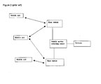
- Figure 2 heuristically shows a portion of a wireless cellular system with base stations wirelessly communicating with mobile units
- Figures 3a-3b illustrate spread spectrum signals with a QPSK (quadrature phase-shift keying) modulation encoder and decoder.
- the multiple access is typically called code division multiple access (CDMA).
- CDMA code division multiple access
- the pseudo-random code may be an orthogonal (Walsh) code, a pseudo-noise (PN) code, a Gold code, or combinations (modulo-2 additions) of such codes.
- the user After despreading the received signal at the correct time instant, the user recovers the corresponding information while the remaining interfering signals appear noise-like.
- the interim standard IS-95 for such CDMA communications employs channels of 1.25 MHz bandwidth and a code pulse interval (chip) T c of 0.8138 microsecond with a transmitted symbol (bit) lasting 64 chips.
- the recent wideband CDMA (WCDMA) proposal employs a 3.84 MHz bandwidth and the CDMA code length applied to each information symbol may vary from 4 chips to 256 chips.
- the CDMA code for each user is typically produced as the modulo-2 addition of a Walsh code with a pseudo-random code (two pseudo-random codes for QPSK modulation) to improve the noise-like nature of the resulting signal.
- a cellular system as illustrated in Figure 2 could employ IS-95 or WCDMA for the air interface between the base station and the mobile units.
- a spread spectrum receiver synchronizes with the transmitter by code acquisition followed by code tracking.
- Code acquisition performs an initial search to bring the phase of the receiver's local code generator to within typically a half chip of the transmitter's, and code tracking maintains fine alignment of chip boundaries of the incoming and locally generated codes.
- Conventional code tracking utilizes a delay-lock loop (DLL) or a tau-dither loop (TDL), both of which are based on the well-known early-late gate principle.
- Figures 3a-3b show the basic blocks of possible transmitters and receivers.
- a RAKE receiver In a multipath situation a RAKE receiver has individual demodulators (fingers) tracking separate paths and combines the results to improve signal-to-noise ratio (SNR), typically according to a method such as maximal ratio combining (MRC) in which the individual detected signals are synchronized and weighted according to their signal strengths.
- SNR signal-to-noise ratio
- MRC maximal ratio combining
- a RAKE receiver usually has a DLL or TDL code tracking loop for each finger together with control circuitry for assigning tracking units to received signal paths.
- Figure 5 illustrates a receiver with N fingres.
- UTRA universal mobile telecommunications system
- FDD frequency division duplex
- TDD time division duplex
- UTRA currently uses radio frames of 10 ms duration and partition each frame into 15 time slots with each time slot consisting of 2560 chips.
- FDD mode the base station and the mobile user transmit on different frequencies
- TDD mode a time slot may be allocated to transmissions by either the base station (downlink) or a mobile user (uplink).
- TDD systems are differentiated from the FDD systems by the presence of interference cancellation at the receiver.
- the spreading gain for TDD systems is small (e.g., 8-16), and the absence of the long spreading code implies that the multi-user multipath interference does not look Gaussian and needs to be canceled at the receiver.
- the uplink dedicated physical data channels (DPDCH n ) and the dedicated physical control channel (DPCCH) are spread using real channelization codes and some DPDCH n are added to form the in-phase stream plus some (optionally) DPDCH's and the DPCCH are added to form the quadrature stream. Then scramble (with a complex scrambling code) the resulting complex stream and use it to modulate the transmission.
- the channelization codes separate the physical channels, and the scrambling code separates cells.
- DPCCH contains pilot bits.
- the dedicated physical channel DPCH effectively includes DPDCH and DPCCH as time-multiplexed fields in a time slot with a portion of the DPCCH bits as pilot bits.
- Serial-to-parallel convert the DPCH bits to I and Q streams and apply the same real channelization codes to spread.
- complex add and apply a complex scrambling code, scale with a gain factor and then add a scaled synchronization channel to use the resulting sum stream to modulate the transmission.
- a physical channel is a burst (data, midamble, and guard) in a particular time slot in a frame.
- the physical synchronization channels essentially provide pilot symbols.
- For spreading apply complex channelization codes which separate the physical channels, and then add and apply a length-16 scrambling code. Use the resulting scrambled complex sum to modulate the transmission.
- the present invention provides a receiver for complex-modulated code-division encoded signals which uses a complex rotation of a complex pseudo-noise code for correlations.
- CDMA code division multiple access
- Preferred embodiment spread spectrum communication systems incorporate preferred embodiment despreading methods.
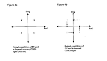
- Preferred embodiment despreading methods apply to QPSK (quadrature phase shift keying) modulated CDMA (code division multiple access) encoded signals and for synchronization acquisition and tracking and for decoding the methods insert a ⁇ /4 rotation in the complex pseudo-noise portion of the encoding; see the receiver of Figure 1.
- Figure 4 illustrates the ⁇ /4 rotation.
- This ⁇ /4 rotation reduces correlation arithmetic operations by essentially replacing a complex multiplication by 1+j with a multiplication by 1 or j. On average this saves two additions and one sign change per multiplication at the cost of a corresponding ⁇ /4 rotation in the transmission channel fading parameter.
- the channel fading parameter estimation using pilot symbols absorbs the ⁇ /4 rotation and avoids any compensating computation to undo the ⁇ /4 rotation.
- Preferred embodiment communications systems base stations and mobile users could each include one or more application specific integrated circuits (ASICs), (programmable) digital signal processors (DSP's), and/or other programmable devices with stored programs for performance of the signal processing of the preferred embodiment methods.
- the base stations and mobile users may also contain analog integrated circuits for amplification of inputs to or outputs from antennas and conversion between analog and digital; and these analog and processor circuits may be integrated on a single die.
- the stored programs may, for example, be in onboard or external ROM, flash EEPROM or FeRAM.
- the antennas may be parts of RAKE detectors with multiple fingers for each user's signals.
- the DSP core could be a TMS320C6xxx or TMS320C5xxx from Texas Instruments.
- Figure 1 illustrates first preferred embodiment receivers and despreading methods.
- a single pseudo-noise code with QPSK modulation as illustrated by the transmitter and receiver of Figures 3a-3b.
- d (k) an input sequence of symbols d (k) where each symbol d (k) has two components: d 1 (k) and d 2 (k); for notational convenience a symbol is expressed as a complex number d 1 (k) + jd 2 (k).
- PN (n) PN 1 (n) + jPN 2 (n) where each component is from the set ⁇ -1,1 ⁇ and the variable n indicates chip number.
- N is the spreading factor (number of chips per symbol) and typically would equal some (small) integral power of 2.
- the real and imaginary parts of this sequence are then used for the in-phase and quadrature modulation (i.e., carriers cos ⁇ t and - sin ⁇ t, respectively) after any chip pulse wave-shaping; see Figure 3a.
- the transmitted signal is thus Re ⁇ G d (k) PN (n)p(t)e j ⁇ t ⁇ where G denotes the gain applied by the transmitter power amplifier.
- This channel fading parameter will essentially be constant over a short time interval, such as a frame of 10 milliseconds (e.g., 38400 chips at a chip rate of 3.84 Mcps).
- the receiver To estimate the channel fading parameter plus gain, G ⁇ , the receiver similarly acquires and decodes a separate pilot signal transmission Re ⁇ G d (k) PN (n)p(t)e j ⁇ t ⁇ where d (k) is a kown constant sequence of symbols, and uses this channel estimate to then recover the data symbols d (k) as G d (k) ⁇ ./ G ⁇ .
- PN * a correlation by PN* consists of complex multiplications by ⁇ 1 ⁇ j plus complex additions. Looking at the four possible values for PN (n):
- the preferred embodiment simplify the correlations to complex multiplications by ⁇ 1 and ⁇ j.
- the four possibilities become:
- the conventional correlations require a precision increase of 1 bit due to the additions.
- the preferred embodiments avoid this 1-bit increase which is an artifact of the conventional correlation approach.
- the second preferred embodiments also rotate a complex pseudo-noise code in conjunction with a channelization code for despreading correlations with QPSK signals.
- a complex pseudo-noise code in conjunction with a channelization code for despreading correlations with QPSK signals.
- presume data bit stream d(k) is spread to the chip rate with real channelization code c d and pilot bit stream d(k) is spread with real channelization code c c ; where both the bits and codes have values ⁇ 1.
- Second preferred embodiment receivers see the incoming signal Re ⁇ G x p(t)e j ⁇ t ⁇ where, as in the foregoing, ⁇ is the transmission channel fading parameter. Then the receiver decodes by estimating the channel fading parameter through correlations with rotated PN* c c plus estimating the data through correlations with rotated PN* c d .
- the correlations of G x ⁇ with rotated PN* c c for each bit is a sum of N terms: ⁇ n G ⁇ d c d (n) d(k) +j ⁇ c C c (n) d(k) ⁇ PN(n) ⁇ e j ⁇ /4 / ⁇ 2 PN*(n)c c (n)
- PN (n) PN *(n) 2 and the orthogonality of the channelization codes yields N jG ⁇ c d(k) 2e j ⁇ /4 / ⁇ 2 ⁇ .
- the correlations with rotated PN* c d yield N jG ⁇ d d(k) 2e j ⁇ /4 / ⁇ 2 ⁇ , so the data bits are recovered.
- UTRA FDD mode uplink can transmit the physical control channel plus up to six physical data channels by using more real channelization codes and adding some coded data channels plus weighting to form the real part of z and adding the remaining coded data channels plus weighting together with the coded pilot channel plus weighting to form the imaginary part of z.
- the channelization codes have a spreading factor from 1 to 16, depending on the number of mobiles in the cell and separate the mobiles. Then apply the complex scrambling code PN derived from a Gold code to z to yield the modulation factor. The scrambling code separates cells.
- UTRA FDD mode downlink analogously spreads data-pilot physical channels (although the data and pilot bits are actually time multiplexed in a single dedicated physical channel, DPCH) and additionally has synchronization physical channels with synchronization codes.
- DPCH dedicated physical channel
- correlating with a rotated conjugate scrambling code times the channelization code yields time-multiplexed data and pilot bits multiplied by the rotated fading parameter (e j ⁇ /4 / ⁇ 2 ⁇ ), so again the data bits can be recovered.
Landscapes
- Engineering & Computer Science (AREA)
- Computer Networks & Wireless Communication (AREA)
- Signal Processing (AREA)
- Mobile Radio Communication Systems (AREA)
- Digital Transmission Methods That Use Modulated Carrier Waves (AREA)
Abstract
Description
Claims (4)
- A method for receiving pseudo-noise code QPSK-modulated signals, comprising:(a) receiving a pseudo-noise code QPSK-modulated signal; and(b) correlating said signal with a complex-rotated version of a conjugate of said pseudo-noise code.
- A receiver for pseudo-noise code QPSK-modulated signals, comprising:(a) an input for receiving a pseudo-noise code QPSK-modulated signal; and(b) a correlator coupled to said input, said correlator including a complex-rotated version of a conjugate of said pseudo-noise code.
- A method for receiving pseudo-noise code QPSK-modulated signals, comprising(a) using a rotated PN sequence which entails the following mapping:
Conventional QPSK PN Bit PN Bit of this claim 1 + j j +1 -j 1 -1 -j -j -1 + j -1 (b) whereby this transformation corresponds to rotation of the PN constellation counter-clockwise by π/4 and scaling by a factor of 1/√2, and this rotation can also be by an angle of - π/4, 3π/4, and -3π/4. - The method of claim 3, wherein:(a) the rotated PN is used to despread the received CDMA signal, as well as to estimate the channel coefficient.(b) whereby advantages obtained include:two addition operations and one sign change operation are saved.one bit of precision in the datapath may be reduced due to the scaling; this saves silicon area.
Applications Claiming Priority (2)
| Application Number | Priority Date | Filing Date | Title |
|---|---|---|---|
| US30942001P | 2001-08-01 | 2001-08-01 | |
| US309420P | 2001-08-01 |
Publications (2)
| Publication Number | Publication Date |
|---|---|
| EP1296461A2 true EP1296461A2 (en) | 2003-03-26 |
| EP1296461A3 EP1296461A3 (en) | 2003-11-19 |
Family
ID=23198160
Family Applications (1)
| Application Number | Title | Priority Date | Filing Date |
|---|---|---|---|
| EP02102086A Withdrawn EP1296461A3 (en) | 2001-08-01 | 2002-08-01 | CDMA despreading using QPSK rotated PN sequences |
Country Status (4)
| Country | Link |
|---|---|
| US (1) | US20030039303A1 (en) |
| EP (1) | EP1296461A3 (en) |
| JP (1) | JP2003110532A (en) |
| KR (1) | KR20030013287A (en) |
Families Citing this family (12)
| Publication number | Priority date | Publication date | Assignee | Title |
|---|---|---|---|---|
| US7161973B2 (en) * | 2002-12-17 | 2007-01-09 | Sbc Properties, L.P. | Pilot aided adaptive minimum mean square interference cancellation and detection |
| US6999467B2 (en) * | 2003-07-28 | 2006-02-14 | Motorola, Inc. | Method and apparatus for transmission and reception within an OFDM communication system |
| WO2009105418A1 (en) | 2008-02-20 | 2009-08-27 | Hobbit Wave | Beamforming devices and methods |
| US9319214B2 (en) * | 2009-10-07 | 2016-04-19 | Rf Micro Devices, Inc. | Multi-mode power amplifier architecture |
| ES2841908T3 (en) | 2010-01-11 | 2021-07-12 | Electronics & Telecommunications Res Inst | Carrier aggregation in wireless communication systems |
| WO2013134506A2 (en) | 2012-03-07 | 2013-09-12 | Hobbit Wave, Inc. | Devices and methods using the hermetic transform |
| US9154353B2 (en) | 2012-03-07 | 2015-10-06 | Hobbit Wave, Inc. | Devices and methods using the hermetic transform for transmitting and receiving signals using OFDM |
| US9531431B2 (en) * | 2013-10-25 | 2016-12-27 | Hobbit Wave, Inc. | Devices and methods employing hermetic transforms for encoding and decoding digital information in spread-spectrum communications systems |
| US9829568B2 (en) | 2013-11-22 | 2017-11-28 | VertoCOMM, Inc. | Radar using hermetic transforms |
| US11304661B2 (en) | 2014-10-23 | 2022-04-19 | VertoCOMM, Inc. | Enhanced imaging devices, and image construction methods and processes employing hermetic transforms |
| US9871684B2 (en) | 2014-11-17 | 2018-01-16 | VertoCOMM, Inc. | Devices and methods for hermetic transform filters |
| US10305717B2 (en) | 2016-02-26 | 2019-05-28 | VertoCOMM, Inc. | Devices and methods using the hermetic transform for transmitting and receiving signals using multi-channel signaling |
Family Cites Families (4)
| Publication number | Priority date | Publication date | Assignee | Title |
|---|---|---|---|---|
| US5463627A (en) * | 1993-02-23 | 1995-10-31 | Matsushita Electric Industrial Co., Ltd. | Frame synchronizing apparatus for quadrature modulation data communication radio receiver |
| US6005887A (en) * | 1996-11-14 | 1999-12-21 | Ericcsson, Inc. | Despreading of direct sequence spread spectrum communications signals |
| WO2000060738A1 (en) * | 1999-04-06 | 2000-10-12 | Ericsson Inc. | Complex matched filter with reduced power consumption |
| US6549564B1 (en) * | 1999-04-08 | 2003-04-15 | Telefonaktiebolaget Lm Ericsson (Publ) | Random access in a mobile telecommunications system |
-
2002
- 2002-07-31 KR KR1020020045381A patent/KR20030013287A/en not_active Withdrawn
- 2002-08-01 EP EP02102086A patent/EP1296461A3/en not_active Withdrawn
- 2002-08-01 JP JP2002224782A patent/JP2003110532A/en active Pending
- 2002-08-01 US US10/210,379 patent/US20030039303A1/en not_active Abandoned
Also Published As
| Publication number | Publication date |
|---|---|
| JP2003110532A (en) | 2003-04-11 |
| EP1296461A3 (en) | 2003-11-19 |
| KR20030013287A (en) | 2003-02-14 |
| US20030039303A1 (en) | 2003-02-27 |
Similar Documents
| Publication | Publication Date | Title |
|---|---|---|
| CA2400934C (en) | Reverse link correlation filter in wireless communication systems | |
| US7099377B2 (en) | Method and device for interference cancellation in a CDMA wireless communication system | |
| JP5039887B2 (en) | Method and apparatus for demodulating a processed signal in transmit diversity mode | |
| EP1063780A2 (en) | Spread spectrum channel estimation sequences | |
| US7110782B2 (en) | Cell search synchronization | |
| JP2771757B2 (en) | Data demodulation circuit of receiver for spread spectrum communication | |
| US6747969B1 (en) | Transmission gap interference measurement | |
| US7133433B2 (en) | Method and apparatus for enhancing data rates in spread spectrum communication systems | |
| KR20000053310A (en) | Despreading of direct sequence spread spectrum communications signals | |
| CA2317751A1 (en) | Method and apparatus for increasing spectral efficiency of cdma systems using direct sequence spread spectrum signals | |
| US20030039303A1 (en) | Receiver and method for CDMA despreading using rotated QPSK PN sequence | |
| US7010016B2 (en) | Method and WCDMA receiver for high-rate and low-rate physical channel reception | |
| US20050276314A1 (en) | Interference eliminating apparatus and method | |
| WO2000035110A1 (en) | Code division multiplex communication method | |
| EP1350338B1 (en) | Time tracking in a non-negligible multipath spacing environment | |
| EP1065825B1 (en) | Time division duplex synchronization | |
| JP2003198500A (en) | Spread spectrum communication system and method | |
| EP1235358B1 (en) | System and method for extracting soft symbols in direct sequence spread spectrum communications | |
| KR20080050211A (en) | Signal transmission method and reception method of communication system | |
| JP2001160798A (en) | Time division duplex synchronization | |
| Jalloul et al. | Enhancing data throughput using quasi-orthogonal functions aggregation for 3G CDMA systems | |
| KR20030083949A (en) | Rake receiver and signal processing method of the same | |
| HK1096781A (en) | Reverse link correlation filter in multi rate cdma wireless communication systems |
Legal Events
| Date | Code | Title | Description |
|---|---|---|---|
| PUAI | Public reference made under article 153(3) epc to a published international application that has entered the european phase |
Free format text: ORIGINAL CODE: 0009012 |
|
| AK | Designated contracting states |
Kind code of ref document: A2 Designated state(s): AT BE BG CH CY CZ DE DK EE ES FI FR GB GR IE IT LI LU MC NL PT SE SK TR Designated state(s): AT BE BG CH CY CZ DE DK EE ES FI FR GB GR IE IT LI LU MC NL PT SE SK TR |
|
| AX | Request for extension of the european patent |
Extension state: AL LT LV MK RO SI |
|
| PUAL | Search report despatched |
Free format text: ORIGINAL CODE: 0009013 |
|
| AK | Designated contracting states |
Kind code of ref document: A3 Designated state(s): AT BE BG CH CY CZ DE DK EE ES FI FR GB GR IE IT LI LU MC NL PT SE SK TR |
|
| AX | Request for extension of the european patent |
Extension state: AL LT LV MK RO SI |
|
| 17P | Request for examination filed |
Effective date: 20040519 |
|
| AKX | Designation fees paid |
Designated state(s): DE FR GB |
|
| 17Q | First examination report despatched |
Effective date: 20040816 |
|
| STAA | Information on the status of an ep patent application or granted ep patent |
Free format text: STATUS: THE APPLICATION IS DEEMED TO BE WITHDRAWN |
|
| 18D | Application deemed to be withdrawn |
Effective date: 20041228 |