EP1296395A1 - Gasket for fuel cell - Google Patents
Gasket for fuel cell Download PDFInfo
- Publication number
- EP1296395A1 EP1296395A1 EP01943832A EP01943832A EP1296395A1 EP 1296395 A1 EP1296395 A1 EP 1296395A1 EP 01943832 A EP01943832 A EP 01943832A EP 01943832 A EP01943832 A EP 01943832A EP 1296395 A1 EP1296395 A1 EP 1296395A1
- Authority
- EP
- European Patent Office
- Prior art keywords
- gasket
- fuel battery
- substrate
- cell
- print circuit
- Prior art date
- Legal status (The legal status is an assumption and is not a legal conclusion. Google has not performed a legal analysis and makes no representation as to the accuracy of the status listed.)
- Granted
Links
Images




Classifications
-
- H—ELECTRICITY
- H01—ELECTRIC ELEMENTS
- H01M—PROCESSES OR MEANS, e.g. BATTERIES, FOR THE DIRECT CONVERSION OF CHEMICAL ENERGY INTO ELECTRICAL ENERGY
- H01M8/00—Fuel cells; Manufacture thereof
- H01M8/04—Auxiliary arrangements, e.g. for control of pressure or for circulation of fluids
- H01M8/04298—Processes for controlling fuel cells or fuel cell systems
- H01M8/04313—Processes for controlling fuel cells or fuel cell systems characterised by the detection or assessment of variables; characterised by the detection or assessment of failure or abnormal function
- H01M8/04537—Electric variables
- H01M8/04544—Voltage
- H01M8/04552—Voltage of the individual fuel cell
-
- H—ELECTRICITY
- H01—ELECTRIC ELEMENTS
- H01M—PROCESSES OR MEANS, e.g. BATTERIES, FOR THE DIRECT CONVERSION OF CHEMICAL ENERGY INTO ELECTRICAL ENERGY
- H01M8/00—Fuel cells; Manufacture thereof
- H01M8/02—Details
- H01M8/0202—Collectors; Separators, e.g. bipolar separators; Interconnectors
- H01M8/0258—Collectors; Separators, e.g. bipolar separators; Interconnectors characterised by the configuration of channels, e.g. by the flow field of the reactant or coolant
-
- H—ELECTRICITY
- H01—ELECTRIC ELEMENTS
- H01M—PROCESSES OR MEANS, e.g. BATTERIES, FOR THE DIRECT CONVERSION OF CHEMICAL ENERGY INTO ELECTRICAL ENERGY
- H01M8/00—Fuel cells; Manufacture thereof
- H01M8/02—Details
- H01M8/0271—Sealing or supporting means around electrodes, matrices or membranes
-
- H—ELECTRICITY
- H01—ELECTRIC ELEMENTS
- H01M—PROCESSES OR MEANS, e.g. BATTERIES, FOR THE DIRECT CONVERSION OF CHEMICAL ENERGY INTO ELECTRICAL ENERGY
- H01M8/00—Fuel cells; Manufacture thereof
- H01M8/02—Details
- H01M8/0271—Sealing or supporting means around electrodes, matrices or membranes
- H01M8/0273—Sealing or supporting means around electrodes, matrices or membranes with sealing or supporting means in the form of a frame
-
- H—ELECTRICITY
- H01—ELECTRIC ELEMENTS
- H01M—PROCESSES OR MEANS, e.g. BATTERIES, FOR THE DIRECT CONVERSION OF CHEMICAL ENERGY INTO ELECTRICAL ENERGY
- H01M8/00—Fuel cells; Manufacture thereof
- H01M8/02—Details
- H01M8/0271—Sealing or supporting means around electrodes, matrices or membranes
- H01M8/0276—Sealing means characterised by their form
-
- H—ELECTRICITY
- H01—ELECTRIC ELEMENTS
- H01M—PROCESSES OR MEANS, e.g. BATTERIES, FOR THE DIRECT CONVERSION OF CHEMICAL ENERGY INTO ELECTRICAL ENERGY
- H01M8/00—Fuel cells; Manufacture thereof
- H01M8/02—Details
- H01M8/0271—Sealing or supporting means around electrodes, matrices or membranes
- H01M8/028—Sealing means characterised by their material
- H01M8/0284—Organic resins; Organic polymers
-
- H—ELECTRICITY
- H01—ELECTRIC ELEMENTS
- H01M—PROCESSES OR MEANS, e.g. BATTERIES, FOR THE DIRECT CONVERSION OF CHEMICAL ENERGY INTO ELECTRICAL ENERGY
- H01M8/00—Fuel cells; Manufacture thereof
- H01M8/02—Details
- H01M8/0271—Sealing or supporting means around electrodes, matrices or membranes
- H01M8/0286—Processes for forming seals
-
- H—ELECTRICITY
- H01—ELECTRIC ELEMENTS
- H01M—PROCESSES OR MEANS, e.g. BATTERIES, FOR THE DIRECT CONVERSION OF CHEMICAL ENERGY INTO ELECTRICAL ENERGY
- H01M8/00—Fuel cells; Manufacture thereof
- H01M8/02—Details
- H01M8/0297—Arrangements for joining electrodes, reservoir layers, heat exchange units or bipolar separators to each other
-
- H—ELECTRICITY
- H01—ELECTRIC ELEMENTS
- H01M—PROCESSES OR MEANS, e.g. BATTERIES, FOR THE DIRECT CONVERSION OF CHEMICAL ENERGY INTO ELECTRICAL ENERGY
- H01M8/00—Fuel cells; Manufacture thereof
- H01M8/04—Auxiliary arrangements, e.g. for control of pressure or for circulation of fluids
- H01M8/04298—Processes for controlling fuel cells or fuel cell systems
- H01M8/04313—Processes for controlling fuel cells or fuel cell systems characterised by the detection or assessment of variables; characterised by the detection or assessment of failure or abnormal function
- H01M8/0432—Temperature; Ambient temperature
- H01M8/04365—Temperature; Ambient temperature of other components of a fuel cell or fuel cell stacks
-
- H—ELECTRICITY
- H01—ELECTRIC ELEMENTS
- H01M—PROCESSES OR MEANS, e.g. BATTERIES, FOR THE DIRECT CONVERSION OF CHEMICAL ENERGY INTO ELECTRICAL ENERGY
- H01M8/00—Fuel cells; Manufacture thereof
- H01M8/04—Auxiliary arrangements, e.g. for control of pressure or for circulation of fluids
- H01M8/04298—Processes for controlling fuel cells or fuel cell systems
- H01M8/04313—Processes for controlling fuel cells or fuel cell systems characterised by the detection or assessment of variables; characterised by the detection or assessment of failure or abnormal function
- H01M8/04664—Failure or abnormal function
- H01M8/04671—Failure or abnormal function of the individual fuel cell
-
- H—ELECTRICITY
- H01—ELECTRIC ELEMENTS
- H01M—PROCESSES OR MEANS, e.g. BATTERIES, FOR THE DIRECT CONVERSION OF CHEMICAL ENERGY INTO ELECTRICAL ENERGY
- H01M8/00—Fuel cells; Manufacture thereof
- H01M8/24—Grouping of fuel cells, e.g. stacking of fuel cells
- H01M8/241—Grouping of fuel cells, e.g. stacking of fuel cells with solid or matrix-supported electrolytes
-
- H—ELECTRICITY
- H01—ELECTRIC ELEMENTS
- H01M—PROCESSES OR MEANS, e.g. BATTERIES, FOR THE DIRECT CONVERSION OF CHEMICAL ENERGY INTO ELECTRICAL ENERGY
- H01M8/00—Fuel cells; Manufacture thereof
- H01M8/04—Auxiliary arrangements, e.g. for control of pressure or for circulation of fluids
- H01M8/04223—Auxiliary arrangements, e.g. for control of pressure or for circulation of fluids during start-up or shut-down; Depolarisation or activation, e.g. purging; Means for short-circuiting defective fuel cells
- H01M8/04246—Short circuiting means for defective fuel cells
-
- H—ELECTRICITY
- H01—ELECTRIC ELEMENTS
- H01M—PROCESSES OR MEANS, e.g. BATTERIES, FOR THE DIRECT CONVERSION OF CHEMICAL ENERGY INTO ELECTRICAL ENERGY
- H01M8/00—Fuel cells; Manufacture thereof
- H01M8/04—Auxiliary arrangements, e.g. for control of pressure or for circulation of fluids
- H01M8/04298—Processes for controlling fuel cells or fuel cell systems
- H01M8/04313—Processes for controlling fuel cells or fuel cell systems characterised by the detection or assessment of variables; characterised by the detection or assessment of failure or abnormal function
- H01M8/0444—Concentration; Density
-
- H—ELECTRICITY
- H01—ELECTRIC ELEMENTS
- H01M—PROCESSES OR MEANS, e.g. BATTERIES, FOR THE DIRECT CONVERSION OF CHEMICAL ENERGY INTO ELECTRICAL ENERGY
- H01M8/00—Fuel cells; Manufacture thereof
- H01M8/04—Auxiliary arrangements, e.g. for control of pressure or for circulation of fluids
- H01M8/04298—Processes for controlling fuel cells or fuel cell systems
- H01M8/04313—Processes for controlling fuel cells or fuel cell systems characterised by the detection or assessment of variables; characterised by the detection or assessment of failure or abnormal function
- H01M8/04537—Electric variables
- H01M8/04574—Current
- H01M8/04582—Current of the individual fuel cell
-
- H—ELECTRICITY
- H01—ELECTRIC ELEMENTS
- H01M—PROCESSES OR MEANS, e.g. BATTERIES, FOR THE DIRECT CONVERSION OF CHEMICAL ENERGY INTO ELECTRICAL ENERGY
- H01M8/00—Fuel cells; Manufacture thereof
- H01M8/10—Fuel cells with solid electrolytes
- H01M8/1004—Fuel cells with solid electrolytes characterised by membrane-electrode assemblies [MEA]
-
- Y—GENERAL TAGGING OF NEW TECHNOLOGICAL DEVELOPMENTS; GENERAL TAGGING OF CROSS-SECTIONAL TECHNOLOGIES SPANNING OVER SEVERAL SECTIONS OF THE IPC; TECHNICAL SUBJECTS COVERED BY FORMER USPC CROSS-REFERENCE ART COLLECTIONS [XRACs] AND DIGESTS
- Y02—TECHNOLOGIES OR APPLICATIONS FOR MITIGATION OR ADAPTATION AGAINST CLIMATE CHANGE
- Y02E—REDUCTION OF GREENHOUSE GAS [GHG] EMISSIONS, RELATED TO ENERGY GENERATION, TRANSMISSION OR DISTRIBUTION
- Y02E60/00—Enabling technologies; Technologies with a potential or indirect contribution to GHG emissions mitigation
- Y02E60/30—Hydrogen technology
- Y02E60/50—Fuel cells
Definitions
- the present invention relates to a gasket for a fuel battery which is used as a seal portion in the fuel battery.
- the present invention is made by taking the matters mentioned above into consideration, and an object of the present invention is to provide a gasket for a fuel battery which is provided with a function capable of performing an operation of specifying a cell or a module generating a voltage drop or a current reduction without dissembling a stack for a fuel battery, by directly measuring a voltage or a current of the cell or the module by a print circuit being electrically in contact with a separator, and a function of taking out an output of a gas sensor or a temperature sensor build in the cell or the module.
- a gasket for a fuel battery characterized in that gaskets are provided on both surfaces of a print circuit for taking out an electric signal within a cell or a module.
- a gasket for a fuel battery as recited in the first aspect mentioned above, characterized in that the print circuit is a flexible print circuit.
- a gasket for a fuel battery for sealing between a pair of separators characterized in that a detecting portion for detecting a voltage or a current of a cell or a module by being electrically connected to a separator in a state of combining a plurality of cells or modules so as to form a stack is integrally assembled.
- a gasket for a fuel battery as recited in the third aspect mentioned above, characterized in that the gasket has a substrate mounted to an electrolyte membrane of a reaction electrode portion, a flexible print circuit lapped over the substrate, an electrode provided in the flexible print circuit and being in contact with the separator, and a gasket fixed to the substrate and holding the flexible print circuit between the gasket and the substrate.
- a gasket for a fuel battery characterized in that a detecting portion having a function of taking out an output of a gas sensor build in a cell or a module is integrally assembled.
- a gasket for a fuel battery characterized in that a detecting portion having a function of taking out an output of a temperature sensor build in a cell or a module is integrally assembled.
- a gasket for a fuel battery characterized in that a signal line for taking out an electric signal within a cell or a module is integrally formed with a gasket substrate in accordance with a printing method or an etching method, and a gasket is integrally formed with the substrate.
- a gasket for a fuel battery as recited in the seventh aspect mentioned above, characterized in that the signal line takes out an electric signal of a current application diagnosis, a temperature, a gas or the like.
- a gasket for a fuel battery as recited in the seventh aspect mentioned above, characterized in that the gasket is formed in a double structure, the signal line is arranged between the gaskets, and an electrode is also arranged there.
- a gasket for a fuel battery as recited in any one of the first to ninth aspects mentioned above, characterized in that a front surface of a circuit formed in the substrate is coated with a protecting member constituted of an insulating membrane.
- the detecting portion and the gasket As a particular structure of the detecting portion and the gasket, as described in the third aspect, it is preferable to have a substrate mounted to an electrolyte membrane of a reaction electrode portion, a flexible print circuit lapped over the substrate, an electrode provided in the flexible print circuit and being in contact with the separator, and a gasket fixed to the substrate and holding the flexible print circuit between the gasket and the substrate.
- the circuit portion may be formed by directly adhering a metal foil to the substrate or printing a conductive ink. Further, the present invention is structured such that the gasket for the fuel battery having the gaskets on both surfaces of the print circuit for taking out the electric signal within the cell or the module is held between the separators, and the electric signal take-out portion for taking out the electric signal (the voltage, the current or the like) is integrally assembled with the seal.
- the gasket for a fuel battery in accordance with the sixth aspect of the present invention provided with the structure mentioned above, in the case that the signal line for taking out the electric signal within the cell or the module is integrally formed with the gasket substrate in accordance with the printing method or the etching method, an occupying space is hardly expanded in comparison with the structure having no signal line, so that it is possible to provide the gasket which saves space and has an excellent practicability in this view.
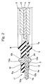
- Figs. 1 and 2 respectively show a cross section of a gasket for a fuel battery in accordance with embodiments of the present invention.
- a circuit is formed on one surface of a substrate 7, and an electrode 13 is attached to one surface.
- the electrode 13 may be attached to both surfaces by forming a hole in the substrate 7.
- the circuit is formed on both surfaces of the substrate 7, and electrodes 13a and 13b are attached to the respective surfaces.
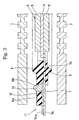
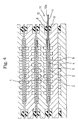
- a state after assembling the structure shown in Fig. 1 is shown in Figs. 3 and 4.
- Fig. 3 is a view after assembling the gasket shown in Fig. 1, and Fig.
- Fig. 4 shows an embodiment of a module unit in which one gasket is provided in a plurality of cells without being provided in each of the cells.
- Fig. 5 is a plan view of the substrate 7.
- the assembled structure shown in Figs. 3 and 4 constructs a cell for a fuel battery corresponding to an assembled complete product, and is structured as follows.
- reaction electrode portion (MEA) 3 is held between a pair of separators 1 and 2.
- the reaction electrode portion 3 is structured such that a positive electrode (GDL: an electrode having a gas diffusion layer) 5 and a negative electrode (GDL: an electrode having a gas diffusion layer) 6 are overlapped on both upper and lower sides of an electrolyte membrane (an ion exchange membrane) 4.
- a substrate (frame) 7 is attached to a peripheral edge portion of the electrolyte membrane 4 in the reaction electrode portion 3 by means of an adhesion or the like, and gaskets (seal rubbers) 8 and 9 are fixed to both upper and lower sides of the substrate 7.
- the upper gasket 8 is closely attached to a lower surface of the upper separator 1 with a predetermined compression margin
- the lower gasket 9 is closely attached to an upper surface of the lower separator 2 with a predetermined compression margin, whereby both of the gaskets 8 and 9 seal between a pair of separators 1 and 2.
- both of the illustrated gaskets 8 and 9 are integrally formed with each other via a communication portion 7a provided in the substrate 7 so as to form a through hole shape, however, may be separately provided in upper and lower portions without the communication portion 7a.
- the substrate 7 is formed with a heat-resistant resin sheet or the like made of a polyimide, a polyether nitrile, a polyethylene terephthalate, an epoxy-based resin, a phenol-based resin or the like, and the gaskets 8 and 9 are formed with a saturated rubber or the like such as a silicone rubber, a fluorine-contained rubber, an ethylene propylene rubber and the like.
- a detecting portion (also called as an electric signal take-out portion) 11 for detecting electric signals (voltages or currents) of the separators 1 and 2 in a state of combining a plurality of cells so as to form a stack is provided at a position outside the gaskets 8 and 9.
- the detecting portion 11 is structured in a manner mentioned below.
- a flexible print circuit 12 is overlapped on the upper surface of the substrate 7 in an unbonded manner, and a membrane-like coating portion 8a integrally formed with the upper gasket 8 covers the flexible print circuit 12 in an unbonded manner. Accordingly, the flexible print circuit 12 is held between the substrate 7 and the coating portion 8a so as to form a sandwich structure. Further, the electrode 13 is placed on the upper surface of the flexible print circuit 12, the electrode 13 protrudes upward from the communication portion 8b formed in the coating portion 8a in the through hole shape, and is in contact with the lower surface of the upper separator 1.
- the flexible print circuit 12 is formed with a foil made of Cu, Ni, Ag, Au or the like, or a conductive ink or the like, and the electrode 13 is formed by a conductive rubber, a conductive resin, a carbon or the like.
- the substrate 7 partly protrudes in a part thereof outside the flat shape of the upper and lower separators 1 and 2, and a part of the flexible print circuit 12 which is not covered by the coating portion 8a is arranged in a protruding portion 7b of the substrate 7.
- This part of the flexible print circuit 12 forms a measurement terminal portion 12a with which a tester for detecting an electric signal is to be in contact, and it is possible to detect the electric signal of the separator and the cell by contacting the tester with the terminal portion 12a.
- the flexible print circuits 12 are respectively overlapped on both upper and lower surfaces of the substrate 7 in an unbonded state, the membrane-like coating portion 8a integrally formed with the upper gasket 8 covers the upper flexible print circuit 12 in an unbonded state, and a membrane-like coating portion 9a integrally formed with the lower gasket 9 covers the lower flexible print circuit 12 in an unbonded state. Accordingly, both of the flexible print circuits 12 are held between the substrate 7 and the coating portions 8a and 9a in a sandwich shape.
- the electrodes 13a and 13b are respectively placed on the upper surface of the upper flexible print circuit 12 and the lower surface of the lower flexible print circuit 12, and the electrodes 13a and 13b protrude upward or downward from the communication portions 8b and 9b formed in the coating portions 8a and 9a in the through hole shape so as to be in contact with the lower surface of the upper separator 1 or the upper surface of the lower separator 2.
- the flexible print circuit 12 is formed with a foil made of Cu, Ni, Ag, Au or the like, or a conductive ink or the like, and the electrodes 13a and 13b are formed with a conductive rubber, a conductive resin, a carbon or the like.
- the substrate 7 partly protrudes in a part thereof outside the flat shape of the upper and lower separators 1 and 2, and a part of the flexible print circuit 12 which is not covered by the coating portions 8a and 9a is arranged in a protruding portion 7b of the substrate 7.
- This part of the flexible print circuit 12 forms measurement terminal portions 12a and 12b with which a tester for detecting an electric signal is to be in contact, and it is possible to detect the electric signal of the separator and the cell by contacting the tester with the terminal portions 12a and 12b.
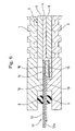
- Fig. 6 shows an embodiment of an invention in accordance with the fifth aspect of the present application.
- the structure is made such that it is possible to measure from an external portion of the cell or the module on the basis of a similar structure to the embodiment mentioned above, by using a gas sensor (also called as a hydrogen sensor) 14 for measuring a concentration of a hydrogen supplied to the cell for the fuel battery mentioned above.
- a gas sensor also called as a hydrogen sensor
- the gas sensor 14 is, for example, of a type of constructing a bridge of a palladium 16 on an alumina substrate 15 having a thickness of 0.25 mm and a size of 5 mm square and detecting a concentration of hydrogen due to a bridge voltage change caused by the hydrogen attached to the palladium 16, and a measurement terminal portion 12a protrudes outward via the flexible print circuit 12 so as to form a detecting portion 17.
- Reference numerals 18 and 19 respectively denote a PI film.
- Fig. 7 shows an embodiment of an invention in accordance with the sixth aspect of the present application.
- the structure is made such that it is possible to measure from an external portion of the cell or the module on the basis of a similar structure to the embodiment mentioned above, by using a temperature sensor 20 for measuring a temperature of an inner portion of the cell for the fuel battery mentioned above.
- the temperature sensor 20 is structured, for example, such that a flattened so-called thermo couple is printed on the flexible print circuit 12 so as to form a sensing portion, and a measurement terminal portion 12a protrudes outward so as to form a detecting portion 21.
- Reference numerals 22 and 23 respectively denote a PI film.
- FIGs. 8 and 9 show an embodiment of an invention in accordance with the seventh aspect of the present application, and the embodiment is structured as follows.
- catalysts 33 are overlapped on both upper and lower sides of an electrolyte membrane (an ion exchange membrane)32 to provide a reaction electrode portion (MEA) 31 and cell seals 34 are respectively provided on both upper and lower sides of a peripheral edge portion 32a in the electrolyte membrane 32.
- Each of the cell seals 34 is obtained by integrally forming a gasket (bead) 36 made of a rubber such as a selective adhesive silicone rubber or the like on one surface of a gasket substrate (frame) 35 made of a resin such as a PET film or the like and applying an adhesive agent 37 made of a PSA or the like on another surface of the substrate 35, and is bonded to the peripheral edge portion 32a of the electrolyte membrane 32 by the adhesive agent 37.
- a gasket (bead) 36 made of a rubber such as a selective adhesive silicone rubber or the like
- frame 35 made of a resin such as a PET film or the like
- an adhesive agent 37 made of a PSA or the like
- a signal line 38 is integrally formed on the upper substrate 35 in the drawing by an integrally forming means on the basis of a printing method or an etching method prior to forming the gasket 36.
- the signal line 38 is in contact with an electrode (GDL: an electrode having a gas diffusion layer) 39 at one end portion 38a thereof after assembling the cell, and outputs an electric signal from another end portion 38b so as to measure the voltage or the current within the cell. Since the signal line 38 is integrally formed with the substrate 35, it is possible to realize a space saving.
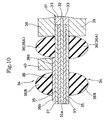
- Fig. 10 shows an embodiment of an invention in accordance with the ninth aspect of the present application, and the embodiment is structured as follows.
- catalysts 33 are overlapped on both upper and lower sides of an electrolyte membrane (an ion exchange membrane)32 to provide a reaction electrode portion (MEA) 31, and cell seals 34 are respectively provided on both upper and lower sides of a peripheral edge portion 32a in the electrolyte membrane 32.
- Each of the cell seals 34 is obtained by integrally forming a gasket (bead) 36 made of a rubber such as a selective adhesive silicone rubber or the like on one surface of a gasket substrate (frame) 35 made of a resin such as a PET film or the like and applying an adhesive agent 37 made of a PSA or the like on another surface of the substrate 35, and is bonded to the peripheral edge portion 32a of the electrolyte membrane 32 by the adhesive agent 37.
- the gasket 36 is provided with an inner peripheral side gasket 36A and an outer peripheral side gasket 36B so as to be structured as an inner and outer double structure.
- a signal line 38 is integrally formed on the upper substrate 35 in the drawing by an integrally forming means on the basis of a printing method or an etching method prior to forming the gasket 36.
- One end portion 38a of the signal line 38 is arranged between the inner and outer gaskets 36A and 36B, and an electrode 40 is mounted to this one end portion 38a. Accordingly, after assembling the cell, the electrode 40 is in contact with the separator (not shown) and outputs an electric signal from another end portion 38b of the signal line 38 so as to measure the voltage or the current within the cell.
- the signal line 38 is integrally formed with the substrate 35, it is possible to realize a space saving.
- the present invention obtains the following effects.
- the detecting portion for taking out the electric signal of the separator and the cell or the module in a state of combining a plurality of cells or modules so as to form the stack is integrally assembled in the gasket, it is possible to detect the electric signal only by connecting the tester to the detecting potion without dissembling the stack, whereby it is possible to easily know from the external portion which of the cells or modules the voltage drop or the current reduction is generated in.
- gasket for the fuel battery in accordance with the fifth aspect of the present invention provided with the structure mentioned above, it is possible to easily measure the concentration of the hydrogen supplied to the cell for the fuel battery from the external portion without dissembling the stack, and in the gasket for the fuel battery in accordance with the sixth aspect of the present invention, it is also possible to easily measure the temperature of the inner portion of the cell for the fuel battery from the external portion without dissembling the stack.
- the gasket for the fuel battery in accordance with the tenth aspect of the present invention provided with the structure mentioned above, since the structure is made such that the front surface of the circuit formed on the substrate is covered by the protecting member constituted of the insulative membrane, it is possible to obtain the effect of preventing the corrosion in the circuit portion, and the effect of preventing the warp due to the difference of thermal expansion between the substrate portion and the circuit portion.
Landscapes
- Life Sciences & Earth Sciences (AREA)
- Engineering & Computer Science (AREA)
- Manufacturing & Machinery (AREA)
- Sustainable Development (AREA)
- Sustainable Energy (AREA)
- Chemical & Material Sciences (AREA)
- Chemical Kinetics & Catalysis (AREA)
- Electrochemistry (AREA)
- General Chemical & Material Sciences (AREA)
- Fuel Cell (AREA)
Abstract
Description
Claims (10)
- A gasket for a fuel battery characterized in that gaskets (8, 9) are provided on both surfaces of a print circuit (12) for taking out an electric signal within a cell or a module.
- A gasket for a fuel battery as claimed in claim 1, characterized in that the print circuit (12) is a flexible print circuit.
- A gasket for a fuel battery for sealing between a pair of separators (1, 2), characterized in that a detecting portion (11) for detecting a voltage or a current of a cell or a module by being electrically connected to the separator (1) and/or the separator (2) in a state of combining a plurality of cells or modules so as to form a stack is integrally assembled.
- A gasket for a fuel battery as claimed in claim 3, characterized in that the gasket has a substrate (7) mounted to an electrolyte membrane (4) of a reaction electrode portion (3), a flexible print circuit (12) lapped over said substrate (7), an electrode (13, 13a, 13b) provided in the flexible print circuit (12) and being in contact with the separator (1, 2), and a gasket (8, 9) fixed to the substrate (7) and holding the flexible print circuit (12) between the gasket and the substrate (7).
- A gasket for a fuel battery characterized in that a detecting portion (17) having a function of taking out an output of a gas sensor (14) build in a cell or a module is integrally assembled.
- A gasket for a fuel battery characterized in that a detecting portion (22) having a function of taking out an output of a temperature sensor (20) build in a cell or a module is integrally assembled.
- A gasket for a fuel battery characterized in that a signal line (38) for taking out an electric signal within a cell or a module is integrally formed with a gasket substrate (35) in accordance with a printing method or an etching method, and a gasket (36) is integrally formed with the substrate (35).
- A gasket for a fuel battery as claimed in claim 7, characterized in that the signal line (38) takes out an electric signal of a current application diagnosis, a temperature, a gas or the like.
- A gasket for a fuel battery as claimed in claim 7, characterized in that gaskets (36A, 36B) is formed in a double structure, the signal line (38) is arranged between the gaskets (36A, 36B), and an electrode (40) is arranged there.
- A gasket for a fuel battery as claimed in any one of claims 1 to 9, characterized in that a front surface (38) of a circuit formed in the substrate is coated by a protecting member constituted by an insulating membrane.
Applications Claiming Priority (3)
| Application Number | Priority Date | Filing Date | Title |
|---|---|---|---|
| JP2000192302 | 2000-06-27 | ||
| JP2000192302 | 2000-06-27 | ||
| PCT/JP2001/005470 WO2002001659A1 (en) | 2000-06-27 | 2001-06-26 | Gasket for fuel cell |
Publications (3)
| Publication Number | Publication Date |
|---|---|
| EP1296395A1 true EP1296395A1 (en) | 2003-03-26 |
| EP1296395A4 EP1296395A4 (en) | 2009-04-15 |
| EP1296395B1 EP1296395B1 (en) | 2012-08-08 |
Family
ID=18691453
Family Applications (1)
| Application Number | Title | Priority Date | Filing Date |
|---|---|---|---|
| EP01943832A Expired - Lifetime EP1296395B1 (en) | 2000-06-27 | 2001-06-26 | Gasket assembly for fuel cell |
Country Status (5)
| Country | Link |
|---|---|
| US (1) | US6805986B2 (en) |
| EP (1) | EP1296395B1 (en) |
| JP (1) | JP3807498B2 (en) |
| AU (1) | AU6633401A (en) |
| WO (1) | WO2002001659A1 (en) |
Cited By (10)
| Publication number | Priority date | Publication date | Assignee | Title |
|---|---|---|---|---|
| WO2005086263A3 (en) * | 2004-02-27 | 2006-07-13 | Freudenberg Nok Gp | Fuel cell gasket having an integrated sensor |
| EP1808922A1 (en) | 2006-01-11 | 2007-07-18 | Samsung SDI Co., Ltd. | Fuel cell with sealing frame comprising contacts for measuring cell voltage |
| WO2007113589A1 (en) * | 2006-03-31 | 2007-10-11 | Johnson Matthey Public Limited Company | Membrane electrode assembly |
| WO2013041869A1 (en) * | 2011-09-21 | 2013-03-28 | Intelligent Energy Limited | Cell voltage monitoring connector system for a fuel cell stack |
| DE102004044685B4 (en) * | 2003-09-19 | 2014-02-20 | Honda Motor Co., Ltd. | Separator, fuel cell and construction of the connection between the terminals of a cell voltage measuring device and a fuel cell |
| FR3037444A1 (en) * | 2015-06-15 | 2016-12-16 | Commissariat Energie Atomique | MEMBRANE ASSEMBLY / ELECTRODES FOR AN ELECTROCHEMICAL REACTOR |
| EP2581631A4 (en) * | 2010-06-14 | 2017-11-15 | NOK Corporation | Gasket |
| DE102016116536A1 (en) | 2016-09-05 | 2018-03-08 | Audi Ag | Sealing element with single cell voltage measuring device for a fuel cell |
| EP3429007A1 (en) * | 2017-07-12 | 2019-01-16 | Commissariat à l'Énergie Atomique et aux Énergies Alternatives | Electrochemical device equipped with a hydrogen sensor |
| FR3119940A1 (en) * | 2021-02-16 | 2022-08-19 | Commissariat à l'Energie Atomique et aux Energies Alternatives | Electrochemical cell with improved peripheral sealing |
Families Citing this family (35)
| Publication number | Priority date | Publication date | Assignee | Title |
|---|---|---|---|---|
| JP3609016B2 (en) * | 2000-10-18 | 2005-01-12 | 本田技研工業株式会社 | Fuel cell seal mounting method and fuel cell |
| JP4530122B2 (en) * | 2001-03-09 | 2010-08-25 | Nok株式会社 | gasket |
| US6793544B2 (en) * | 2003-02-05 | 2004-09-21 | General Motors Corporation | Corrosion resistant fuel cell terminal plates |
| US7104545B2 (en) * | 2003-02-18 | 2006-09-12 | Delphi Technologies, Inc. | Method of forming a gasket assembly for a PEM fuel cell assembly |
| JP4381759B2 (en) * | 2003-09-19 | 2009-12-09 | 本田技研工業株式会社 | Separator and fuel cell |
| CN1323458C (en) * | 2003-10-14 | 2007-06-27 | 胜光科技股份有限公司 | Manufacturing method of laminated integrated fuel cell system and fuel cell system thereof |
| JP4474976B2 (en) * | 2004-04-02 | 2010-06-09 | Nok株式会社 | Fuel cell wiring |
| JP4806901B2 (en) * | 2004-04-15 | 2011-11-02 | Nok株式会社 | Fuel cell wiring |
| JP4806902B2 (en) * | 2004-04-15 | 2011-11-02 | Nok株式会社 | Fuel cell wiring |
| JP4857525B2 (en) * | 2004-04-15 | 2012-01-18 | Nok株式会社 | FUEL CELL WIRING AND METHOD OF ASSEMBLING FUEL CELL WIRING TO FUEL CELL |
| JP4806900B2 (en) * | 2004-04-15 | 2011-11-02 | Nok株式会社 | Fuel cell wiring |
| JP4586413B2 (en) * | 2004-05-17 | 2010-11-24 | Nok株式会社 | Fuel cell |
| JP4459793B2 (en) | 2004-11-29 | 2010-04-28 | 株式会社日立製作所 | Fuel cell end plate and fuel cell |
| WO2007018005A1 (en) * | 2005-08-10 | 2007-02-15 | Daikin Industries, Ltd. | Sealing material |
| JP4607827B2 (en) * | 2006-01-11 | 2011-01-05 | 三星エスディアイ株式会社 | Fuel cell system |
| US7648782B2 (en) * | 2006-03-20 | 2010-01-19 | Tokyo Electron Limited | Ceramic coating member for semiconductor processing apparatus |
| US8216740B2 (en) * | 2006-12-12 | 2012-07-10 | Bose Corporation | Fuel cell |
| US7790305B2 (en) * | 2007-02-20 | 2010-09-07 | Freudenberg-Nok General Partnership | Gas diffusion layers with integrated seals having interlocking features |
| US7771885B2 (en) * | 2007-03-30 | 2010-08-10 | Panasonic Corporation | Polymer electrolyte fuel cell and manufacturing method for electrode-membrane-frame assembly |
| JP2008262847A (en) * | 2007-04-13 | 2008-10-30 | Nok Corp | Sticking component for fuel cell |
| KR100980995B1 (en) * | 2007-06-19 | 2010-09-07 | 현대자동차주식회사 | Intelligent Electrode Membrane for Fuel Cell |
| JP4954024B2 (en) * | 2007-11-09 | 2012-06-13 | タイガースポリマー株式会社 | Fuel cell packing and seal structure |
| JP4954025B2 (en) * | 2007-11-09 | 2012-06-13 | タイガースポリマー株式会社 | Method for forming packing for fuel cell |
| US8557473B2 (en) * | 2007-12-11 | 2013-10-15 | Bose Corporation | Fuel cell polymer electrolyte membrane |
| JP5625594B2 (en) * | 2010-08-02 | 2014-11-19 | Nok株式会社 | Connector seal and manufacturing method thereof |
| JP5778056B2 (en) * | 2012-02-20 | 2015-09-16 | 本田技研工業株式会社 | Fuel cell |
| JP5781957B2 (en) * | 2012-02-20 | 2015-09-24 | 本田技研工業株式会社 | Fuel cell |
| GB2516931B (en) * | 2013-08-07 | 2019-12-25 | Intelligent Energy Ltd | Interface seal for a fuel cartridge |
| JP6383203B2 (en) * | 2014-07-25 | 2018-08-29 | Nok株式会社 | Manufacturing method of plate-integrated gasket |
| TWI536651B (en) * | 2015-06-05 | 2016-06-01 | 元智大學 | Cell module |
| JP6260609B2 (en) * | 2015-12-02 | 2018-01-17 | トヨタ自動車株式会社 | Fuel cell and fuel cell manufacturing method |
| KR102845708B1 (en) * | 2019-05-16 | 2025-08-12 | 현대자동차주식회사 | Elastomer cell frame for fuel cell and Manufacturing method thereof and Fuel cell stack comprising thereof |
| DE102020210410A1 (en) | 2020-08-17 | 2022-02-17 | Robert Bosch Gesellschaft mit beschränkter Haftung | Fuel cell assembly, fuel cell stack and method of making a fuel cell assembly |
| KR102666059B1 (en) * | 2021-11-19 | 2024-05-14 | 테라릭스 주식회사 | A Manofold Gasket for Fuel Cell |
| SE2350842A1 (en) * | 2023-07-05 | 2025-01-06 | Powercell Sweden Ab | Membrane electrode assembly |
Family Cites Families (15)
| Publication number | Priority date | Publication date | Assignee | Title |
|---|---|---|---|---|
| JPS60236464A (en) * | 1984-05-10 | 1985-11-25 | Fuji Electric Corp Res & Dev Ltd | Monitoring method of electrolyte retaining amount of fuel cell |
| JPH0439869A (en) * | 1990-06-04 | 1992-02-10 | Mitsubishi Electric Corp | Control method of electrolyte in fuel cell |
| JP2516274B2 (en) * | 1990-07-27 | 1996-07-24 | 株式会社日立製作所 | Fuel cell power plant |
| JP3021853B2 (en) * | 1991-09-25 | 2000-03-15 | ソニー株式会社 | Disk unit |
| JPH05159794A (en) * | 1991-12-10 | 1993-06-25 | Ishikawajima Harima Heavy Ind Co Ltd | Fuel cell stack and defective cell replacement method for the fuel cell stack |
| US5629104A (en) * | 1994-11-23 | 1997-05-13 | Detroit Center Tool | Modular electrical energy device |
| US6242690B1 (en) * | 1995-09-25 | 2001-06-05 | Ericsson Inc. | Gasket system for EMI isolation |
| JP3681467B2 (en) * | 1996-03-29 | 2005-08-10 | 株式会社エクォス・リサーチ | Fuel cell power generator and method of operating the same |
| US5763113A (en) * | 1996-08-26 | 1998-06-09 | General Motors Corporation | PEM fuel cell monitoring system |
| JP4000607B2 (en) * | 1996-09-06 | 2007-10-31 | トヨタ自動車株式会社 | Fuel cell power generation apparatus and method |
| US6190793B1 (en) * | 1997-07-16 | 2001-02-20 | Ballard Power Systems Inc. | Electrochemical fuel cell stack with an improved compression assembly |
| JPH11309747A (en) * | 1998-04-30 | 1999-11-09 | Mitsubishi Plastics Ind Ltd | Method for producing silicone resin-metal composite |
| GB9814123D0 (en) * | 1998-07-01 | 1998-08-26 | British Gas Plc | Electrochemical fuel cell |
| JP4576646B2 (en) * | 1999-09-30 | 2010-11-10 | アイシン精機株式会社 | Fuel cell |
| US6410176B1 (en) * | 2000-07-31 | 2002-06-25 | Plug Power, Inc. | Voltage monitoring system for a fuel cell stack |
-
2001
- 2001-06-26 EP EP01943832A patent/EP1296395B1/en not_active Expired - Lifetime
- 2001-06-26 JP JP2002505704A patent/JP3807498B2/en not_active Expired - Fee Related
- 2001-06-26 WO PCT/JP2001/005470 patent/WO2002001659A1/en not_active Ceased
- 2001-06-26 AU AU66334/01A patent/AU6633401A/en not_active Abandoned
- 2001-06-26 US US10/049,637 patent/US6805986B2/en not_active Expired - Lifetime
Cited By (17)
| Publication number | Priority date | Publication date | Assignee | Title |
|---|---|---|---|---|
| DE102004044685B4 (en) * | 2003-09-19 | 2014-02-20 | Honda Motor Co., Ltd. | Separator, fuel cell and construction of the connection between the terminals of a cell voltage measuring device and a fuel cell |
| WO2005086263A3 (en) * | 2004-02-27 | 2006-07-13 | Freudenberg Nok Gp | Fuel cell gasket having an integrated sensor |
| EP1808922A1 (en) | 2006-01-11 | 2007-07-18 | Samsung SDI Co., Ltd. | Fuel cell with sealing frame comprising contacts for measuring cell voltage |
| US7927758B2 (en) | 2006-01-11 | 2011-04-19 | Samsung Sdi Co., Ltd. | Gasket being capable of measuring voltage and fuel cell system having the same |
| WO2007113589A1 (en) * | 2006-03-31 | 2007-10-11 | Johnson Matthey Public Limited Company | Membrane electrode assembly |
| EP2581631A4 (en) * | 2010-06-14 | 2017-11-15 | NOK Corporation | Gasket |
| WO2013041869A1 (en) * | 2011-09-21 | 2013-03-28 | Intelligent Energy Limited | Cell voltage monitoring connector system for a fuel cell stack |
| GB2494879B (en) * | 2011-09-21 | 2014-09-24 | Intelligent Energy Ltd | Cell voltage monitoring connector system for a fuel cell stack |
| KR20190135565A (en) * | 2011-09-21 | 2019-12-06 | 인텔리전트 에너지 리미티드 | Cell voltage monitoring connector system for a fuel cell stack |
| KR102102286B1 (en) | 2011-09-21 | 2020-04-20 | 인텔리전트 에너지 리미티드 | Cell voltage monitoring connector system for a fuel cell stack |
| FR3037444A1 (en) * | 2015-06-15 | 2016-12-16 | Commissariat Energie Atomique | MEMBRANE ASSEMBLY / ELECTRODES FOR AN ELECTROCHEMICAL REACTOR |
| DE102016116536A1 (en) | 2016-09-05 | 2018-03-08 | Audi Ag | Sealing element with single cell voltage measuring device for a fuel cell |
| EP3429007A1 (en) * | 2017-07-12 | 2019-01-16 | Commissariat à l'Énergie Atomique et aux Énergies Alternatives | Electrochemical device equipped with a hydrogen sensor |
| FR3068990A1 (en) * | 2017-07-12 | 2019-01-18 | Commissariat A L'energie Atomique Et Aux Energies Alternatives | ELECTROCHEMICAL DEVICE COMPRISING A HYDROGEN SENSOR |
| US10790524B2 (en) | 2017-07-12 | 2020-09-29 | Commissariat A L'energie Atomique Et Aux Energies Alternatives | Electrochemical device comprising a hydrogen sensor |
| FR3119940A1 (en) * | 2021-02-16 | 2022-08-19 | Commissariat à l'Energie Atomique et aux Energies Alternatives | Electrochemical cell with improved peripheral sealing |
| WO2022175233A1 (en) * | 2021-02-16 | 2022-08-25 | Symbio | Electrochemical cell with improved peripheral sealing |
Also Published As
| Publication number | Publication date |
|---|---|
| AU6633401A (en) | 2002-01-08 |
| EP1296395B1 (en) | 2012-08-08 |
| WO2002001659A1 (en) | 2002-01-03 |
| JP3807498B2 (en) | 2006-08-09 |
| EP1296395A4 (en) | 2009-04-15 |
| US20030013000A1 (en) | 2003-01-16 |
| US6805986B2 (en) | 2004-10-19 |
Similar Documents
| Publication | Publication Date | Title |
|---|---|---|
| US6805986B2 (en) | Gasket for fuel battery | |
| JPWO2002001659A1 (en) | Fuel cell gaskets | |
| US7791349B2 (en) | Fuel cell diagnostic apparatus and diagnostic method | |
| CN102576915B (en) | There is the battery unit of integrated sensing platform | |
| CN111937227B (en) | Metal-air battery and method for manufacturing metal-air battery | |
| JP4568044B2 (en) | Membrane electrode composite module, fuel cell, electronic device, and manufacturing method of membrane electrode composite module | |
| JP4469414B2 (en) | Membrane electrode assembly | |
| US20100003568A1 (en) | Fuel cell and fuel cell system including the same | |
| US20110136029A1 (en) | Fuel cell and temperature measurement method | |
| US20050191537A1 (en) | Fuel cell gasket having an integrated sensor | |
| JP2008293766A (en) | Fuel cell stack | |
| CN111141428A (en) | Automobile seat pressure sensor, membrane switch sheet and preparation method thereof, automobile | |
| JP4192824B2 (en) | Fuel cell seal | |
| JP5765062B2 (en) | Battery, power supply device, battery driving system, and method for detecting expansion of battery | |
| JP2001076747A (en) | Solid polymer fuel cell | |
| US11038185B2 (en) | Water detection device and power generation cell | |
| JP7596018B2 (en) | Pouch-type battery cell containing flexible printed circuit board | |
| KR100804703B1 (en) | Electrical output measuring device and stack for fuel cell comprising same | |
| CN217765300U (en) | Flexible pressure sensor | |
| CN211291818U (en) | Car seat pressure sensor, membrane switch piece and car | |
| JP4474976B2 (en) | Fuel cell wiring | |
| JP4453423B2 (en) | Fuel cell wiring | |
| CN221008816U (en) | Key structure for portable densimeter and portable densimeter | |
| US20220407134A1 (en) | Temperature measurement device, temperature measurement method, and battery system | |
| JP4806902B2 (en) | Fuel cell wiring |
Legal Events
| Date | Code | Title | Description |
|---|---|---|---|
| PUAI | Public reference made under article 153(3) epc to a published international application that has entered the european phase |
Free format text: ORIGINAL CODE: 0009012 |
|
| 17P | Request for examination filed |
Effective date: 20020620 |
|
| AK | Designated contracting states |
Kind code of ref document: A1 Designated state(s): AT BE CH CY DE DK ES FI FR GB GR IE IT LI LU MC NL PT SE TR |
|
| AX | Request for extension of the european patent |
Extension state: AL LT LV MK RO SI |
|
| RBV | Designated contracting states (corrected) |
Designated state(s): DE FR GB |
|
| A4 | Supplementary search report drawn up and despatched |
Effective date: 20090313 |
|
| 17Q | First examination report despatched |
Effective date: 20090803 |
|
| GRAP | Despatch of communication of intention to grant a patent |
Free format text: ORIGINAL CODE: EPIDOSNIGR1 |
|
| RTI1 | Title (correction) |
Free format text: GASKET ASSEMBLY FOR FUEL CELL |
|
| GRAS | Grant fee paid |
Free format text: ORIGINAL CODE: EPIDOSNIGR3 |
|
| GRAA | (expected) grant |
Free format text: ORIGINAL CODE: 0009210 |
|
| AK | Designated contracting states |
Kind code of ref document: B1 Designated state(s): DE FR GB |
|
| REG | Reference to a national code |
Ref country code: GB Ref legal event code: FG4D |
|
| REG | Reference to a national code |
Ref country code: DE Ref legal event code: R096 Ref document number: 60146959 Country of ref document: DE Effective date: 20121011 |
|
| PLBE | No opposition filed within time limit |
Free format text: ORIGINAL CODE: 0009261 |
|
| STAA | Information on the status of an ep patent application or granted ep patent |
Free format text: STATUS: NO OPPOSITION FILED WITHIN TIME LIMIT |
|
| 26N | No opposition filed |
Effective date: 20130510 |
|
| REG | Reference to a national code |
Ref country code: DE Ref legal event code: R097 Ref document number: 60146959 Country of ref document: DE Effective date: 20130510 |
|
| REG | Reference to a national code |
Ref country code: FR Ref legal event code: PLFP Year of fee payment: 16 |
|
| REG | Reference to a national code |
Ref country code: FR Ref legal event code: PLFP Year of fee payment: 17 |
|
| PGFP | Annual fee paid to national office [announced via postgrant information from national office to epo] |
Ref country code: FR Payment date: 20170511 Year of fee payment: 17 Ref country code: GB Payment date: 20170621 Year of fee payment: 17 |
|
| PGFP | Annual fee paid to national office [announced via postgrant information from national office to epo] |
Ref country code: DE Payment date: 20180612 Year of fee payment: 18 |
|
| GBPC | Gb: european patent ceased through non-payment of renewal fee |
Effective date: 20180626 |
|
| PG25 | Lapsed in a contracting state [announced via postgrant information from national office to epo] |
Ref country code: FR Free format text: LAPSE BECAUSE OF NON-PAYMENT OF DUE FEES Effective date: 20180630 Ref country code: GB Free format text: LAPSE BECAUSE OF NON-PAYMENT OF DUE FEES Effective date: 20180626 |
|
| REG | Reference to a national code |
Ref country code: DE Ref legal event code: R119 Ref document number: 60146959 Country of ref document: DE |
|
| PG25 | Lapsed in a contracting state [announced via postgrant information from national office to epo] |
Ref country code: DE Free format text: LAPSE BECAUSE OF NON-PAYMENT OF DUE FEES Effective date: 20200101 |