EP1296372A2 - Heat dissipating material and manufacturing method thereof - Google Patents
Heat dissipating material and manufacturing method thereof Download PDFInfo
- Publication number
- EP1296372A2 EP1296372A2 EP02020961A EP02020961A EP1296372A2 EP 1296372 A2 EP1296372 A2 EP 1296372A2 EP 02020961 A EP02020961 A EP 02020961A EP 02020961 A EP02020961 A EP 02020961A EP 1296372 A2 EP1296372 A2 EP 1296372A2
- Authority
- EP
- European Patent Office
- Prior art keywords
- heat dissipating
- based metal
- metal
- dissipating material
- iron
- Prior art date
- Legal status (The legal status is an assumption and is not a legal conclusion. Google has not performed a legal analysis and makes no representation as to the accuracy of the status listed.)
- Withdrawn
Links
Images


Classifications
-
- B—PERFORMING OPERATIONS; TRANSPORTING
- B32—LAYERED PRODUCTS
- B32B—LAYERED PRODUCTS, i.e. PRODUCTS BUILT-UP OF STRATA OF FLAT OR NON-FLAT, e.g. CELLULAR OR HONEYCOMB, FORM
- B32B15/00—Layered products comprising a layer of metal
- B32B15/01—Layered products comprising a layer of metal all layers being exclusively metallic
- B32B15/013—Layered products comprising a layer of metal all layers being exclusively metallic one layer being formed of an iron alloy or steel, another layer being formed of a metal other than iron or aluminium
- B32B15/015—Layered products comprising a layer of metal all layers being exclusively metallic one layer being formed of an iron alloy or steel, another layer being formed of a metal other than iron or aluminium the said other metal being copper or nickel or an alloy thereof
-
- B—PERFORMING OPERATIONS; TRANSPORTING
- B22—CASTING; POWDER METALLURGY
- B22D—CASTING OF METALS; CASTING OF OTHER SUBSTANCES BY THE SAME PROCESSES OR DEVICES
- B22D19/00—Casting in, on, or around objects which form part of the product
- B22D19/14—Casting in, on, or around objects which form part of the product the objects being filamentary or particulate in form
-
- H—ELECTRICITY
- H10—SEMICONDUCTOR DEVICES; ELECTRIC SOLID-STATE DEVICES NOT OTHERWISE PROVIDED FOR
- H10W—GENERIC PACKAGES, INTERCONNECTIONS, CONNECTORS OR OTHER CONSTRUCTIONAL DETAILS OF DEVICES COVERED BY CLASS H10
- H10W40/00—Arrangements for thermal protection or thermal control
- H10W40/20—Arrangements for cooling
- H10W40/25—Arrangements for cooling characterised by their materials
- H10W40/255—Arrangements for cooling characterised by their materials having a laminate or multilayered structure, e.g. direct bond copper [DBC] ceramic substrates
-
- H—ELECTRICITY
- H10—SEMICONDUCTOR DEVICES; ELECTRIC SOLID-STATE DEVICES NOT OTHERWISE PROVIDED FOR
- H10W—GENERIC PACKAGES, INTERCONNECTIONS, CONNECTORS OR OTHER CONSTRUCTIONAL DETAILS OF DEVICES COVERED BY CLASS H10
- H10W70/00—Package substrates; Interposers; Redistribution layers [RDL]
- H10W70/01—Manufacture or treatment
- H10W70/02—Manufacture or treatment of conductive package substrates serving as an interconnection, e.g. of metal plates
-
- H—ELECTRICITY
- H10—SEMICONDUCTOR DEVICES; ELECTRIC SOLID-STATE DEVICES NOT OTHERWISE PROVIDED FOR
- H10W—GENERIC PACKAGES, INTERCONNECTIONS, CONNECTORS OR OTHER CONSTRUCTIONAL DETAILS OF DEVICES COVERED BY CLASS H10
- H10W72/00—Interconnections or connectors in packages
- H10W72/30—Die-attach connectors
-
- H—ELECTRICITY
- H10—SEMICONDUCTOR DEVICES; ELECTRIC SOLID-STATE DEVICES NOT OTHERWISE PROVIDED FOR
- H10W—GENERIC PACKAGES, INTERCONNECTIONS, CONNECTORS OR OTHER CONSTRUCTIONAL DETAILS OF DEVICES COVERED BY CLASS H10
- H10W72/00—Interconnections or connectors in packages
- H10W72/30—Die-attach connectors
- H10W72/381—Auxiliary members
-
- Y—GENERAL TAGGING OF NEW TECHNOLOGICAL DEVELOPMENTS; GENERAL TAGGING OF CROSS-SECTIONAL TECHNOLOGIES SPANNING OVER SEVERAL SECTIONS OF THE IPC; TECHNICAL SUBJECTS COVERED BY FORMER USPC CROSS-REFERENCE ART COLLECTIONS [XRACs] AND DIGESTS
- Y10—TECHNICAL SUBJECTS COVERED BY FORMER USPC
- Y10T—TECHNICAL SUBJECTS COVERED BY FORMER US CLASSIFICATION
- Y10T428/00—Stock material or miscellaneous articles
- Y10T428/12—All metal or with adjacent metals
- Y10T428/12014—All metal or with adjacent metals having metal particles
- Y10T428/12028—Composite; i.e., plural, adjacent, spatially distinct metal components [e.g., layers, etc.]
- Y10T428/12063—Nonparticulate metal component
-
- Y—GENERAL TAGGING OF NEW TECHNOLOGICAL DEVELOPMENTS; GENERAL TAGGING OF CROSS-SECTIONAL TECHNOLOGIES SPANNING OVER SEVERAL SECTIONS OF THE IPC; TECHNICAL SUBJECTS COVERED BY FORMER USPC CROSS-REFERENCE ART COLLECTIONS [XRACs] AND DIGESTS
- Y10—TECHNICAL SUBJECTS COVERED BY FORMER USPC
- Y10T—TECHNICAL SUBJECTS COVERED BY FORMER US CLASSIFICATION
- Y10T428/00—Stock material or miscellaneous articles
- Y10T428/12—All metal or with adjacent metals
- Y10T428/12014—All metal or with adjacent metals having metal particles
- Y10T428/12028—Composite; i.e., plural, adjacent, spatially distinct metal components [e.g., layers, etc.]
- Y10T428/12063—Nonparticulate metal component
- Y10T428/12069—Plural nonparticulate metal components
-
- Y—GENERAL TAGGING OF NEW TECHNOLOGICAL DEVELOPMENTS; GENERAL TAGGING OF CROSS-SECTIONAL TECHNOLOGIES SPANNING OVER SEVERAL SECTIONS OF THE IPC; TECHNICAL SUBJECTS COVERED BY FORMER USPC CROSS-REFERENCE ART COLLECTIONS [XRACs] AND DIGESTS
- Y10—TECHNICAL SUBJECTS COVERED BY FORMER USPC
- Y10T—TECHNICAL SUBJECTS COVERED BY FORMER US CLASSIFICATION
- Y10T428/00—Stock material or miscellaneous articles
- Y10T428/12—All metal or with adjacent metals
- Y10T428/12493—Composite; i.e., plural, adjacent, spatially distinct metal components [e.g., layers, joint, etc.]
-
- Y—GENERAL TAGGING OF NEW TECHNOLOGICAL DEVELOPMENTS; GENERAL TAGGING OF CROSS-SECTIONAL TECHNOLOGIES SPANNING OVER SEVERAL SECTIONS OF THE IPC; TECHNICAL SUBJECTS COVERED BY FORMER USPC CROSS-REFERENCE ART COLLECTIONS [XRACs] AND DIGESTS
- Y10—TECHNICAL SUBJECTS COVERED BY FORMER USPC
- Y10T—TECHNICAL SUBJECTS COVERED BY FORMER US CLASSIFICATION
- Y10T428/00—Stock material or miscellaneous articles
- Y10T428/12—All metal or with adjacent metals
- Y10T428/12493—Composite; i.e., plural, adjacent, spatially distinct metal components [e.g., layers, joint, etc.]
- Y10T428/12528—Semiconductor component
-
- Y—GENERAL TAGGING OF NEW TECHNOLOGICAL DEVELOPMENTS; GENERAL TAGGING OF CROSS-SECTIONAL TECHNOLOGIES SPANNING OVER SEVERAL SECTIONS OF THE IPC; TECHNICAL SUBJECTS COVERED BY FORMER USPC CROSS-REFERENCE ART COLLECTIONS [XRACs] AND DIGESTS
- Y10—TECHNICAL SUBJECTS COVERED BY FORMER USPC
- Y10T—TECHNICAL SUBJECTS COVERED BY FORMER US CLASSIFICATION
- Y10T428/00—Stock material or miscellaneous articles
- Y10T428/12—All metal or with adjacent metals
- Y10T428/12493—Composite; i.e., plural, adjacent, spatially distinct metal components [e.g., layers, joint, etc.]
- Y10T428/12771—Transition metal-base component
- Y10T428/12861—Group VIII or IB metal-base component
- Y10T428/12951—Fe-base component
Definitions
- the present invention relates to a heat dissipating material and a method for manufacturing the material. More particularly, the present invention pertains to a heat dissipating material suitable for heat dissipating substrate, on which electronic components such as semiconductor devices are mounted.
- heat dissipating board heat dissipating substrate
- methods for implementing semiconductor devices on a heat dissipating board include a method using a heat sink and a method using a heat spreader.
- a heat sink using method is shown in Fig. 4.
- a heat sink 42 is fixed to an aluminum base 41, which forms a case, with screws (not shown).
- the heat sink 42 may be soldered to the aluminum base 41.
- An insulated substrate 43 is fixed to the heat sink 42,
- the insulated substrate 43 has metal (Al) layer 43a on each side.
- An electronic component 44 such as a semiconductor device is implemented onto the upper metal layer 43a of the insulated substrate 43.
- the insulated substrate 43 is made of aluminum nitride (AlN).
- the heat sink 42 is made of a material having a low expansion coefficient and a high thermal conductivity.
- the heat sink 42 is made of metal matrix composite, which has ceramics dispersed in a metal matrix layer. For example, a composite having SiC particles dispersed in an aluminum main component is used.
- Aluminum nitride of the insulated substrate 43 arid the metal matrix composite of the heat sink 42 are expensive. Therefore, an inexpensive method using a heat spreader has also been proposed.
- a heat spreader using method is shown in Fig. 5-
- a high insulated thermal technology (HITT) substrate 45 is secured to the upper surface of an aluminum base 41, which forms a case, with silicone grease.
- the HITT substrate 45 includes an aluminum main body 45a, an epoxy resin insulating layer 45b, and a metal (copper) layer 45c.
- the insulating layer 45b is adhered to an opposite side of the main body 45a from the aluminum base 41.
- the metal layer 45c is laminated on the insulating layer 45b.
- a heat spreader 46 is soldered onto the HITT substrate 45.
- An electronic component 44 is soldered onto the heat spreader 46.
- heat spreaders are made of Cu, Mo or a three-layer laminated material of Cu/Invar/Cu.
- Invar is an alloy containing 36% of weight of Ni. The remaining portion of Invar is substantially Fe.
- Cu has a relatively great linear expansion coefficient of 17 ⁇ 10 -6 /°C. Therefore, matching between Cu and the electronic component 44, the linear expansion coefficient of which is 4 ⁇ 10 -6 /°C, is not satisfactory. Also, since Mo has a relatively low linear expansion coefficient of 4 ⁇ 10 -6 /°C to 5 ⁇ 10 -6 /°C, matching between Mo and the HITT substrate 45 is not satisfactory.
- the three-layer laminated material of Cu/Invar/Cu which is used nowadays, has a linear expansion coefficient of 10 ⁇ 10 -6 /°C to 11 ⁇ 10 -6 /°C.
- the laminated material has satisfactory matching with the electronic component 44 and the HITT substrate 45.
- Invar contained in the laminated material has a significantly small thermal conductivity.
- Invar is held between Cu layers having a relatively high thermal conductivity (390W/(m ⁇ K)
- the heat expansion of the heat spreader 46 in the direction of thickness is as small as 30W/(m ⁇ K).
- the heat conductivity of the three-layer laminated material is as small as 60W/(m ⁇ K), which is not sufficient for dissipating heat. Further, since Invar is held between Cu layers, the cost is increased.
- a plate-shaped heat dissipating material is provided.
- the main component of the material is an iron-based metal, and at least the surface of the material is covered with a rustproof metal.
- the present also provides an electronic module including a plate shaped heat dissipating material and an electronic element.
- the main component of the material is an iron-based metal, and at least the surface of the material is covered with a rustproof metal.
- the electronic element is mounted on the heat dissipating material.
- the present invention further provides a method for manufacturing a heat dissipating material.
- the method includes: placing metal shaving in a mold; pouring a molten aluminum-based metal or molten copper into the mold and impregnating the metal shaving with the molten aluminum-based metal or the molten copper; and taking out the molded material as the heat dissipating material from the mold after the aluminum-based metal or the copper is solidified.
- the present invention provides another method for manufacturing a heat dissipating material.
- the method includes: forming a porous sintered compact with powder of an iron-based metal; placing the sintered compact in a mold; pouring and pressurizing a molten aluminum-based metal or molten copper into the mold, and impregnating the sintered compact with the molten aluminum-based metal or the molten copper; and taking out the molded material as the heat dissipating material from the mold after the aluminum-based metal or the copper is solidified.
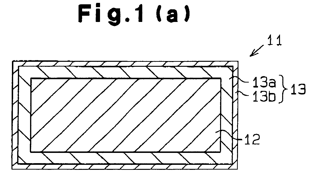
- Fig. 1(a) is schematic cross-sectional view illustrating a heat dissipating material.
- the heat dissipating material is a heat spreader 11.
- Fig. 1(b) is a schematic cross-sectional view illustrating a semiconductor module (electronic module) using the heat spreader 11.
- the heat spreader 11 includes an electromagnetic soft iron sheet 12 and a protective layer formed on the surface of the iron sheet 12.
- the protective layer is a plating layer 13. That is, the heat spreader 11 is a plate the main component of which is an iron-based metal. At least the surface of the heat spreader 11 is coated with rustproof metal. Pure iron, cast iron, carbon steel, or low alloy steel having alloy content element no more than 5% may be used as the iron-based metal.
- the iron-based metal is the electromagnetic soft iron.
- the plating layer 13 includes an electrolytic Ni plating layer 13a and an Ni-B plating layer 13b.
- the electrolytic Ni plating layer 13a is formed on the surface of the electromagnetic soft iron sheet 12.
- the Ni-B plating layer 13b is the outermost layer.
- the thickness of the electrolytic Ni plating layer 13a is 20 ⁇ m.
- the thickness of the Ni-B plating layer 13b is a few micrometers.
- the Ni-B plating layer 13b reduces pinholes in the electrolytic Ni plating layer 13a and improves the corrosion resistance of the electrolytic Ni plating layer 13a.
- the thickness of the electromagnetic soft iron sheet 12 is, for example, 1 mm. Even if the thickness of the iron sheet 12 is changed, the thickness of the electrolytic Ni plating layer 13a and the thickness of the Ni-B plating layer 13b will be substantially constant.
- a high insulated thermal technology (HITT) substrate 15 is soldered onto an aluminum base 14 as shown in Fig. 1(b).
- the aluminum base 14 forms a case.
- the HITT substrate 15 includes an aluminum main body 15a, an epoxy resin insulating layer 15b, and a metal (copper) layer 15c.
- the insulating layer 15b is adhered to an opposite side of the main body 15a from the aluminum base 14.
- the metal layer 15c is laminated on the insulating layer 15b.
- the heat spreader 11 is soldered onto the HITT substrate 15.
- An electronic component (silicon chip) 16 such as a semiconductor device is soldered onto the heat spreader 11.
- the electromagnetic soft iron has a favorable matching with the electronic component 16 and with the HITT substrate 15 since the linear expansion coefficient of the electromagnetic soft iron is approximately 11 ⁇ 10 -6 /°C. Further, since the thermal conductivity of the soft magnetic material is 80W/(m ⁇ K), the heat dissipating property of the heat spreader 11 is better than that of the three-layer laminated material.
- This embodiment provides the following advantages.
- FIG. 2 A second embodiment of the present invention will now be described with reference to Figs. 2 to 3(b).
- the embodiment of Figs. 2 to 3(b) is significantly different from the embodiment of Figs. 1(a) and 1(b) in that the iron-based material is powder.
- Fig. 2 is a schematic cross-sectional view illustrating a heat spreader 11.
- the heat spreader 11 includes a metallic matrix 17 made of an aluminum-based metal or copper.
- the metallic matrix 17 is charged with powder 18 of an iron-based metal. That is, the heat spreader 11 is formed by impregnating the powder 18 of iron-based metal with aluminum-based metal or copper as the metallic matrix 17 and then solidifying the matrix 17.
- the aluminum-based metal refers to aluminum or aluminum alloy.
- the powder 18 of iron-based metal is covered by the rustproof metallic matrix 17. Therefore, as in the first embodiment of Figs. 1(a) and 1(b), at least the surface of the heat spreader 11 of the second embodiment is coated with rustproof metal.
- Metal shaving is used as the powder 18 of the iron-based metal.
- shaving of cast iron swarf of case metal
- the volume content of the powder 18 is determined such that the linear expansion coefficient of the heat spreader 11 is 14 ⁇ 10 -6 /°C to 15 ⁇ 10 -6 /°C.
- the volume content of the powder 18 is set to 49 volume% to 51 volume%.
- the maximum diameter of the particles in the powder 18 is, for example, 180 ⁇ m, and the average diameter is, for example 100 ⁇ m.
- a method for manufacturing the heat spreader 11, which is constructed as above, will hereafter be described with reference to Figs 3(a) and 3(b).
- a predetermined amount of the powder 18 of cast iron is charged into a mold 19.
- molten metal 20, which is molten aluminum metal or molten copper is poured into the mold 19 to impregnate the powder 18 with the molten metal 20.
- the molded material is taken out of the mold 19. The manufacture of the heat spreader 11 is thus completed.
- the embodiment shown in Figs. 2 to 3(b) has the following advantages.
- the heat spreader 11 is formed by charging the powder 18 of the iron-based metal in the metallic matrix 17 of the aluminum-based metal or copper, and the linear expansion coefficient of the heat spreader 11 is 14x10 -6 /°C to 15 ⁇ 10 -6 /°C. Therefore, by adjusting the volume content of the powder 18, the linear expansion coefficient of the heat spreader 11 can be optimized. Accordingly, the heat spreader 11 has an improved thermal conductivity and heat dissipating property compared to a three-layer laminated material of Cu/Invar/Cu.
- the heat spreader 11 is formed simply charging the powder 18 of cast iron into the mold 19, impregnating the powder 18 with the molten metal 20, and then solidifying the powder 18 and the molten metal 20.
- the heat spreader 11 is manufactured at a lower cost.
- Metal dust of cast iron is used as the powder 18 of the iron-based metal, which further reduces the costs.
- the plating layer 13 formed on the electromagnetic soft iron sheet 12 need not include both of the electrolytic Ni plating layer 13a and the electrolytic Ni-B plating layer 13b.
- the plating layer 13 may include only the electrolytic Ni plating layer 13a.
- the plating layer 13 may be replaced with a plating layer of a metal other than Ni as long as the metal has a low electrical resistance.
- the powder 18 instead of the cast iron, other type of iron-based metal may be used as the powder 18.
- other type of iron-based metal may be used as the powder 18.
- carbon steel, low alloy steel, or electromagnetic sofL iron may be used. This modification has the same advantages as the second embodiment. As long as the volume content is the same, the heat dissipating property of material using electromagnetic soft iron powder is better than a material using cast iron powder.
- a sintered porous preform may be formed with the powder 18 of iron-based metal, and the dissipating material may be formed by impregnating the sintered compact with aluminum-based metal or copper.
- the sintered preform is placed in a mold, and pressurized molten aluminum-based metal or pressurized molten copper is cast in the mold. After being solidified, the molded material is taken out of the mold.
- the porosity of the sintered compact is 49 to 51%. The porosity is computed based on the volume and the weight of the sintered compact.
- the sintered preform of the iron-based metal is formed and impregnated with molten metal.
- the cost is increased.
- the cost for forming sintered preform is lower than a case in which a preform is formed by thermal spraying. Since aluminum-based metal has a lower melting temperature than copper and is lighter than copper, aluminum-based metal is more preferable the metal for impregnation.
- a composite was formed using a Cr containing iron as the iron-based metal and aluminum as molten metal. The volume content of the iron-based metal was approximately 60%.
- the heat conductivity was 140W/(m ⁇ K) to 150W/(m ⁇ K), and the linear expansion coefficient was 15 ⁇ 10 -6 /°C.
- the plating layer 13 may be cladded with metal foil.
- the electromagnetic soft iron sheet 12 may be cladded with Ni foil. Compared to the case where the coating layer is formed only with the electrolytic Ni plating layer, the number of pinholes is reduced and creation of voids in solder is suppressed, which improves the reliability.
- the heat dissipating material may be used for purposes other than implementing of semiconductor devices.
- the mold 19 need not be made of metal.
- the mold 19 may be made of ceramics.
Landscapes
- Engineering & Computer Science (AREA)
- Mechanical Engineering (AREA)
- Cooling Or The Like Of Semiconductors Or Solid State Devices (AREA)
- Laminated Bodies (AREA)
Abstract
Description
Claims (13)
- A plate-shaped heat dissipating material, characterized in that the main component of the material is an iron-based metal, and wherein at least the surface of the material is covered with a rustproof metal.
- The heat dissipating material according to claim 1, characterized by:a plate made of the iron-based metal; anda protective layer made of the rustproof metal, wherein the protective layer covers the surface of the plate.
- The heat dissipating material according to claim 2, characterized in that the plate is made of an electromagnetic soft iron, and wherein the protective layer is a plating layer.
- The heat dissipating material according to claim 3, characterized in that the plating layer includes an inner Ni plating layer and an outer Ni-B plating layer.
- The heat dissipating material according to claim 2, characterized in that the plate is made of an electromagnetic soft iron, and wherein the protective layer is made of an Ni foil.
- The heat dissipating material according to claim 1, characterized in that the rustproof metal is an aluminum-based metal or copper, wherein the heat dissipating material is formed by impregnating powder of the iron-based metal with a metallic matrix, which is the aluminum-based metal or the copper, and wherein the volume content of the iron-based metal is determined such that the linear expansion coefficient of the heat dissipating material is 14×10-6/°C to 15×10-6/°C.
- The heat dissipating material according to claim 1, characterized in that the rustproof metal is an aluminum-based metal or copper, wherein the heat dissipating material is formed by impregnating a porous sintered compact made of the iron-based metal powder with a metallic matrix, which is the aluminum-based metal or the copper, and wherein the volume content of the iron-based metal is determined such that the linear expansion coefficient of the heat dissipating material is 14×10-6/°C to 15×10-6/°C.
- The heat dissipating material according to claim 6 or 7, characterized in that the iron-based metal powder is metal shaving.
- An electronic module characterized by:a heat dissipating material according to any one of claims 1 to 8; andan electronic element mounted on the heat dissipating material.
- A method for manufacturing a heat dissipating material, characterized by:placing metal shaving in a mold;pouring a molten aluminum-based metal or molten copper into the mold and impregnating the metal shaving with the molten aluminum-based metal or the molten copper; andtaking out the molded material as the heat dissipating material from the mold after the aluminum-based metal or the copper is solidified.
- The method according to claim 10, characterized in that the volume content of the metal shaving is determined such that the linear expansion coefficient of the heat dissipating material is 14×10-6/°C to 15×10-6/°C.
- A method for manufacturing a heat dissipating material, characterized by:forming a porous sintered compact with powder of an iron-based metal;placing the sintered compact in a mold;pouring and pressurizing a molten aluminum-based metal or molten copper into the mold, and impregnating the sintered compact with the molten aluminum-based metal or the molten copper; andtaking out the molded material as the heat dissipating material from the mold after the aluminum-based metal or the copper is solidified.
- The method according to claim 12, characterized in that the iron-based metal powder is sintered such that the porosity of the sintered compact is 49 to 51%.
Applications Claiming Priority (2)
| Application Number | Priority Date | Filing Date | Title |
|---|---|---|---|
| JP2001288122 | 2001-09-21 | ||
| JP2001288122A JP2003100968A (en) | 2001-09-21 | 2001-09-21 | Heat radiating material and method of manufacturing the same |
Publications (2)
| Publication Number | Publication Date |
|---|---|
| EP1296372A2 true EP1296372A2 (en) | 2003-03-26 |
| EP1296372A3 EP1296372A3 (en) | 2006-07-26 |
Family
ID=19110819
Family Applications (1)
| Application Number | Title | Priority Date | Filing Date |
|---|---|---|---|
| EP02020961A Withdrawn EP1296372A3 (en) | 2001-09-21 | 2002-09-19 | Heat dissipating material and manufacturing method thereof |
Country Status (3)
| Country | Link |
|---|---|
| US (1) | US6753093B2 (en) |
| EP (1) | EP1296372A3 (en) |
| JP (1) | JP2003100968A (en) |
Cited By (1)
| Publication number | Priority date | Publication date | Assignee | Title |
|---|---|---|---|---|
| EP1717333A1 (en) * | 2005-04-27 | 2006-11-02 | Kabushiki Kaisha Toyota Jidoshokki | Method of manufacturing composite material |
Families Citing this family (11)
| Publication number | Priority date | Publication date | Assignee | Title |
|---|---|---|---|---|
| US7077859B2 (en) * | 2000-12-22 | 2006-07-18 | Avantec Vascular Corporation | Apparatus and methods for variably controlled substance delivery from implanted prostheses |
| US7027304B2 (en) * | 2001-02-15 | 2006-04-11 | Integral Technologies, Inc. | Low cost thermal management device or heat sink manufactured from conductive loaded resin-based materials |
| EP1452614B1 (en) * | 2001-11-09 | 2017-12-27 | Sumitomo Electric Industries, Ltd. | Sintered diamond having high thermal conductivity |
| JP2004103700A (en) * | 2002-09-06 | 2004-04-02 | Toyota Industries Corp | Low expansion member, method of manufacturing the same, and semiconductor device using low expansion member |
| FR2863186B1 (en) * | 2003-12-04 | 2006-12-15 | Toyota Jidoshokki Kk | COMPOSITE COMPOSITE ELEMENT, IRON-BASED POROUS SUBSTANCE FOR COMPOSITE CASTING ELEMENTS AND PRESSURE CASING METHODS OF MANUFACTURING THIS CASING UNDER PRESSURE COMPRESSOR COMPONENT ELEMENT |
| JP2007150289A (en) * | 2005-11-04 | 2007-06-14 | Mitsubishi Materials Corp | Radiator, radiator, power module substrate and power module |
| JP5273922B2 (en) * | 2006-12-28 | 2013-08-28 | 株式会社アライドマテリアル | Heat dissipation member and semiconductor device |
| JP5782741B2 (en) * | 2010-07-15 | 2015-09-24 | 富士通株式会社 | Electronics |
| US9420734B2 (en) * | 2014-04-01 | 2016-08-16 | Advanced Micro Devices, Inc. | Combined electromagnetic shield and thermal management device |
| CN110620088B (en) * | 2018-06-20 | 2021-11-12 | 比亚迪股份有限公司 | Heat dissipation element and IGBT module |
| CN110620091A (en) * | 2018-06-20 | 2019-12-27 | 比亚迪股份有限公司 | Heat dissipation bottom plate, heat dissipation element, preparation method of heat dissipation element and IGBT module |
Family Cites Families (16)
| Publication number | Priority date | Publication date | Assignee | Title |
|---|---|---|---|---|
| JPS6016431A (en) | 1983-07-08 | 1985-01-28 | Hitachi Cable Ltd | Semiconductor device |
| US4569692A (en) * | 1983-10-06 | 1986-02-11 | Olin Corporation | Low thermal expansivity and high thermal conductivity substrate |
| US4894293A (en) * | 1988-03-10 | 1990-01-16 | Texas Instruments Incorporated | Circuit system, a composite metal material for use therein, and a method for making the material |
| JPH01261848A (en) * | 1988-04-13 | 1989-10-18 | Toshiba Corp | Semiconductor device |
| JPH03173166A (en) * | 1989-11-30 | 1991-07-26 | Aichi Steel Works Ltd | Heat-dissipating substrate for semiconductor |
| JP2566341B2 (en) * | 1990-11-24 | 1996-12-25 | 株式会社日立製作所 | Semiconductor device |
| JPH0945815A (en) * | 1995-08-03 | 1997-02-14 | Sumitomo Electric Ind Ltd | Semiconductor package, plate member for the package, and method for manufacturing the same |
| US5981085A (en) * | 1996-03-21 | 1999-11-09 | The Furukawa Electric Co., Inc. | Composite substrate for heat-generating semiconductor device and semiconductor apparatus using the same |
| US5844310A (en) * | 1996-08-09 | 1998-12-01 | Hitachi Metals, Ltd. | Heat spreader semiconductor device with heat spreader and method for producing same |
| JPH10256443A (en) * | 1997-03-12 | 1998-09-25 | Dowa Mining Co Ltd | Heat sink body for power module |
| US6132676A (en) * | 1997-06-30 | 2000-10-17 | Massachusetts Institute Of Technology | Minimal thermal expansion, high thermal conductivity metal-ceramic matrix composite |
| US6129993A (en) * | 1998-02-13 | 2000-10-10 | Hitachi Metals, Ltd. | Heat spreader and method of making the same |
| US6084775A (en) * | 1998-12-09 | 2000-07-04 | International Business Machines Corporation | Heatsink and package structures with fusible release layer |
| US6381094B1 (en) * | 1999-07-23 | 2002-04-30 | Hardayal Singh Gill | Shield structure with a heat sink layer for dissipating heat from a read sensor |
| JP4342050B2 (en) | 1999-09-20 | 2009-10-14 | 日本ベアリング株式会社 | Sliding device |
| JP3812321B2 (en) * | 2000-10-25 | 2006-08-23 | 株式会社豊田自動織機 | Heat sink and manufacturing method thereof |
-
2001
- 2001-09-21 JP JP2001288122A patent/JP2003100968A/en active Pending
-
2002
- 2002-09-19 EP EP02020961A patent/EP1296372A3/en not_active Withdrawn
- 2002-09-20 US US10/247,953 patent/US6753093B2/en not_active Expired - Fee Related
Cited By (1)
| Publication number | Priority date | Publication date | Assignee | Title |
|---|---|---|---|---|
| EP1717333A1 (en) * | 2005-04-27 | 2006-11-02 | Kabushiki Kaisha Toyota Jidoshokki | Method of manufacturing composite material |
Also Published As
| Publication number | Publication date |
|---|---|
| JP2003100968A (en) | 2003-04-04 |
| US20030066621A1 (en) | 2003-04-10 |
| EP1296372A3 (en) | 2006-07-26 |
| US6753093B2 (en) | 2004-06-22 |
Similar Documents
| Publication | Publication Date | Title |
|---|---|---|
| US6753093B2 (en) | Heat dissipating material and manufacturing method thereof | |
| CN101361184B (en) | Aluminum/silicon carbide composite and heat radiation part making use of the same | |
| KR100637635B1 (en) | Silicon carbide composite, method for producing it and heat dissipation device employing it | |
| CN101427367B (en) | Aluminum-silicon carbide composite and heat dissipation component using same | |
| CN109690760B (en) | Heat sink and method for manufacturing the same | |
| US4894293A (en) | Circuit system, a composite metal material for use therein, and a method for making the material | |
| KR20100105734A (en) | Heat sink and heat sink manufacturing method | |
| JPWO2006030676A1 (en) | Aluminum-silicon carbide composite | |
| CN101273450A (en) | Heat dissipation module and manufacturing method thereof | |
| EP0365275B1 (en) | A composite material heat-dissipating member for a semiconductor element and method of its fabrication | |
| JP2005145746A (en) | Ceramic circuit board integrated aluminum-silicon carbide composite and manufacturing method thereof | |
| WO2015115649A1 (en) | Silicon carbide complex, method for manufacturing same, and heat dissipation component using same | |
| KR101691724B1 (en) | Heat radiation plate for high power devices | |
| JPH08186204A (en) | Heat sink and method of manufacturing the same | |
| JP2022132241A (en) | Molded article and its manufacturing method | |
| KR20210038085A (en) | Electronic component | |
| JP4127379B2 (en) | Method for producing aluminum-silicon carbide composite | |
| JP2002285259A (en) | Heat dissipating member for electronic equipment and method of manufacturing the same | |
| JP4407858B2 (en) | Module structure | |
| JP2001294494A (en) | Metal ceramic composite and heat dissipation member | |
| JP3732193B2 (en) | Aluminum-silicon carbide composite and method for producing the same | |
| JP2003188324A (en) | Heat dissipation base material, method of manufacturing heat dissipation base material, and semiconductor device including heat dissipation base material | |
| JP2001217364A (en) | Al-SiC COMPOSITE | |
| JP2780129B2 (en) | Composite sintered body and its manufacturing method and application | |
| JP2024041251A (en) | Electronic component joining method |
Legal Events
| Date | Code | Title | Description |
|---|---|---|---|
| PUAI | Public reference made under article 153(3) epc to a published international application that has entered the european phase |
Free format text: ORIGINAL CODE: 0009012 |
|
| AK | Designated contracting states |
Kind code of ref document: A2 Designated state(s): AT BE BG CH CY CZ DE DK EE ES FI FR GB GR IE IT LI LU MC NL PT SE SK TR Designated state(s): AT BE BG CH CY CZ DE DK EE ES FI FR GB GR IE IT LI LU MC NL PT SE SK TR |
|
| AX | Request for extension of the european patent |
Extension state: AL LT LV MK RO SI |
|
| RIC1 | Information provided on ipc code assigned before grant |
Ipc: 7B 32B 15/01 B Ipc: 7H 01L 23/373 A |
|
| PUAL | Search report despatched |
Free format text: ORIGINAL CODE: 0009013 |
|
| AK | Designated contracting states |
Kind code of ref document: A3 Designated state(s): AT BE BG CH CY CZ DE DK EE ES FI FR GB GR IE IT LI LU MC NL PT SE SK TR |
|
| AX | Request for extension of the european patent |
Extension state: AL LT LV MK RO SI |
|
| RIC1 | Information provided on ipc code assigned before grant |
Ipc: H01L 21/48 20060101ALI20060619BHEP Ipc: B32B 15/01 20060101ALI20060619BHEP Ipc: H01L 23/373 20060101AFI20021203BHEP |
|
| 17P | Request for examination filed |
Effective date: 20060918 |
|
| STAA | Information on the status of an ep patent application or granted ep patent |
Free format text: STATUS: THE APPLICATION HAS BEEN WITHDRAWN |
|
| 18W | Application withdrawn |
Effective date: 20070201 |