EP1296173A1 - Multiple sharing type display device - Google Patents
Multiple sharing type display device Download PDFInfo
- Publication number
- EP1296173A1 EP1296173A1 EP01945723A EP01945723A EP1296173A1 EP 1296173 A1 EP1296173 A1 EP 1296173A1 EP 01945723 A EP01945723 A EP 01945723A EP 01945723 A EP01945723 A EP 01945723A EP 1296173 A1 EP1296173 A1 EP 1296173A1
- Authority
- EP
- European Patent Office
- Prior art keywords
- display
- display device
- mask
- eye
- glasses
- Prior art date
- Legal status (The legal status is an assumption and is not a legal conclusion. Google has not performed a legal analysis and makes no representation as to the accuracy of the status listed.)
- Granted
Links
Images





Classifications
-
- G—PHYSICS
- G06—COMPUTING OR CALCULATING; COUNTING
- G06F—ELECTRIC DIGITAL DATA PROCESSING
- G06F3/00—Input arrangements for transferring data to be processed into a form capable of being handled by the computer; Output arrangements for transferring data from processing unit to output unit, e.g. interface arrangements
- G06F3/01—Input arrangements or combined input and output arrangements for interaction between user and computer
- G06F3/011—Arrangements for interaction with the human body, e.g. for user immersion in virtual reality
-
- G—PHYSICS
- G02—OPTICS
- G02B—OPTICAL ELEMENTS, SYSTEMS OR APPARATUS
- G02B27/00—Optical systems or apparatus not provided for by any of the groups G02B1/00 - G02B26/00, G02B30/00
- G02B27/01—Head-up displays
- G02B27/017—Head mounted
-
- G—PHYSICS
- G02—OPTICS
- G02B—OPTICAL ELEMENTS, SYSTEMS OR APPARATUS
- G02B27/00—Optical systems or apparatus not provided for by any of the groups G02B1/00 - G02B26/00, G02B30/00
- G02B27/01—Head-up displays
- G02B27/017—Head mounted
- G02B27/0172—Head mounted characterised by optical features
-
- G—PHYSICS
- G02—OPTICS
- G02B—OPTICAL ELEMENTS, SYSTEMS OR APPARATUS
- G02B30/00—Optical systems or apparatus for producing three-dimensional [3D] effects, e.g. stereoscopic images
- G02B30/20—Optical systems or apparatus for producing three-dimensional [3D] effects, e.g. stereoscopic images by providing first and second parallax images to an observer's left and right eyes
- G02B30/34—Stereoscopes providing a stereoscopic pair of separated images corresponding to parallactically displaced views of the same object, e.g. three-dimensional [3D] slide viewers
-
- H—ELECTRICITY
- H04—ELECTRIC COMMUNICATION TECHNIQUE
- H04N—PICTORIAL COMMUNICATION, e.g. TELEVISION
- H04N13/00—Stereoscopic video systems; Multi-view video systems; Details thereof
- H04N13/30—Image reproducers
- H04N13/302—Image reproducers for viewing without the aid of special glasses, i.e. using autostereoscopic displays
- H04N13/32—Image reproducers for viewing without the aid of special glasses, i.e. using autostereoscopic displays using arrays of controllable light sources; using moving apertures or moving light sources
-
- H—ELECTRICITY
- H04—ELECTRIC COMMUNICATION TECHNIQUE
- H04N—PICTORIAL COMMUNICATION, e.g. TELEVISION
- H04N13/00—Stereoscopic video systems; Multi-view video systems; Details thereof
- H04N13/30—Image reproducers
- H04N13/366—Image reproducers using viewer tracking
- H04N13/368—Image reproducers using viewer tracking for two or more viewers
-
- H—ELECTRICITY
- H04—ELECTRIC COMMUNICATION TECHNIQUE
- H04N—PICTORIAL COMMUNICATION, e.g. TELEVISION
- H04N13/00—Stereoscopic video systems; Multi-view video systems; Details thereof
- H04N13/30—Image reproducers
- H04N13/398—Synchronisation thereof; Control thereof
-
- G—PHYSICS
- G02—OPTICS
- G02B—OPTICAL ELEMENTS, SYSTEMS OR APPARATUS
- G02B27/00—Optical systems or apparatus not provided for by any of the groups G02B1/00 - G02B26/00, G02B30/00
- G02B27/01—Head-up displays
- G02B27/017—Head mounted
- G02B2027/0178—Eyeglass type
-
- H—ELECTRICITY
- H04—ELECTRIC COMMUNICATION TECHNIQUE
- H04N—PICTORIAL COMMUNICATION, e.g. TELEVISION
- H04N13/00—Stereoscopic video systems; Multi-view video systems; Details thereof
- H04N13/20—Image signal generators
- H04N13/286—Image signal generators having separate monoscopic and stereoscopic modes
-
- H—ELECTRICITY
- H04—ELECTRIC COMMUNICATION TECHNIQUE
- H04N—PICTORIAL COMMUNICATION, e.g. TELEVISION
- H04N13/00—Stereoscopic video systems; Multi-view video systems; Details thereof
- H04N13/30—Image reproducers
- H04N13/332—Displays for viewing with the aid of special glasses or head-mounted displays [HMD]
- H04N13/339—Displays for viewing with the aid of special glasses or head-mounted displays [HMD] using spatial multiplexing
-
- H—ELECTRICITY
- H04—ELECTRIC COMMUNICATION TECHNIQUE
- H04N—PICTORIAL COMMUNICATION, e.g. TELEVISION
- H04N13/00—Stereoscopic video systems; Multi-view video systems; Details thereof
- H04N13/30—Image reproducers
- H04N13/332—Displays for viewing with the aid of special glasses or head-mounted displays [HMD]
- H04N13/344—Displays for viewing with the aid of special glasses or head-mounted displays [HMD] with head-mounted left-right displays
Definitions
- the present invention relates to a display device.
- it is related to display device allowing a plurality of users to share a common display device.
- Techniques of displaying three-dimensional images are generally classified into a technique where a stereoscopic image is formed using an appropriate method and having the viewer of such image view it without assistance, and a binocular disparity technique devised so that, instead of a stereoscopic image, a right-eye view and a left-eye view of a flat image is formed and the right-eye view is viewed by the right eye and the left-eye view is viewed by the left eye.
- Typical examples of the former include holography and integral photography, and the latter includes three-dimensional movies where polarized glasses or liquid crystal shutters are used, and three-dimensional television using lenticular film.
- the binocular disparity technique is based on ergonomics, and provides three-dimensional images giving an enhanced 'real' feeling, and superior immersion and sensory feelings. However, it is not possible to freely change the viewpoint from which the three-dimensional object shown is viewed to coordinate with the user's movements using this technique by itself.
- a method which modifies the three-dimensional image in accordance with the viewpoint and position of the viewer a device (e.g., magnetic sensors or the like) worn for measuring the position of the head (viewpoint) of the viewer plus the binocular disparity technique allows the three-dimensional image to be viewed relative to the viewpoint position.
- a device e.g., magnetic sensors or the like
- the number of users for which viewpoint movement within real-space can be reflected in the virtual world is limited to one person for each display.
- An object of the present invention is to provide a multi-person shared display device capable of displaying in response to viewpoint movement in real space. Another object of the present invention is to provide a multi-person shared display device capable of displaying a three dimensional image.
- the present invention is a multi-person shared display device, in which a display device is shared by a plurality of users; it is characterized by comprising: a display device, which displays a plurality of video for a plurality of users on a screen; a display mask, which is disposed so as to cover said display device separated by a fixed distance and has a sufficiently large hole; a position sensor, which detects a location of a user in real space corresponding to said display device; and a processing device, which is dynamically combined with said one display device and said position sensor, and displays an image corresponding to each user upon said display device in accordance with the position of the user through said position sensor.
- the proposed multi-person shared display device uses a display mask in which a hole is formed and covers the display device so as to hide portions besides the hole, allowing different display regions upon the display device to be set in accordance with the viewpoint position within real space of each user. This makes it possible to perform display in response to viewpoint movements of a plurality of users.
- Video to be displayed upon a display device can include video for three-dimensional viewing.
- each user wears a plurality of glasses for separating said video for three-dimensional viewing displayed into that for the right eye and that for the left eye, and the plurality of video for three dimensional viewing shown on said display device, are images allowing separation between that for the right eye and that for the left eye through said plurality of glasses.
- glasses in which shutters for the right eye and for the left eye open and close can be used as said glasses; and said processing device can be dynamically combined with said glasses.
- said glasses and said position sensor By forming said glasses and said position sensor as an integral unit, the position of a user can be found with little error.
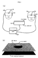
- FIG 1(a) is a diagram showing a configuration of a multi-person shared three-dimensional display device according to an embodiment of the present invention.
- two users 140 and 150 of a multi-person shared three-dimensional display device each have on liquid crystal shutter glasses 142, 152, respectively, and also have a respective position sensor 144, 154 attached.
- the users view an image displayed upon a display screen 110 via the liquid crystal shutters.
- the liquid crystal shutter glasses 142, 152, position sensors 144, 154, and display device 110 are connected to a processing device 130. In conformity with the input from the position sensors, the processing apparatus 130 displays an image upon the display at a region corresponding to each respective user.
- the display device 110 is configured from a display 112 and a display mask 114, which covers and hides a portion thereof.
- the display mask 114 is set at a position separated only an appropriate distance away from a display surface 116.
- a hole 118 is formed in the display mask 114, and through only that portion can the surface 116 of the display 112 be seen.
- the viewable region upon the display surface varies depending on the viewpoint position of the user.
- the viewpoint position of a user moves
- the region viewable by the user also changes depending on that movement. Accordingly, by detecting viewpoint position using the position sensor and displaying at a region befitting that viewpoint position, it is possible to adapt to the movement of the viewpoint position of the user.
- a magnetic sensor having 6 degrees of freedom can be used as the viewpoint position detection sensor.
- the magnetic sensor can detect the current position by detecting magnetic flux cutoff in every respective direction x, y, and z. Assuming that the direction of the line of sight faces the center of the hole upon the mask and that a line connecting both eyes parallels the horizontal surface, that direction of the line of sight can be calculated in real time from the viewpoint position detected.
- the position detection sensor may be constructed integrated in the liquid crystal shutter glasses.
- the processing device 130 is provided comprising projecting an image for the respective right and left viewpoint derived and time-divided, alternating displaying upon a display 112 synchronous to the liquid crystal shutters.
- this system displays enlargement thereof.
- This allows, for example, a display frequency of 120 Hz to be divided into 60 Hz to show the right and left images.
- the liquid crystal shutters switch between both right and left, viewable and non-viewable, by synchronizing with the image refresh rate.
- the fact that the display 112 is viewed through the liquid crystal shutter glasses makes it possible to obtain images that correspond to the respective right and left viewpoints, thereby allowing three-dimensional viewing.
- the top and lower halves are output one at a time; however, in what manner division and display are carried out, or whether display is carried out without division, or if display is accomplished through interlacing or so forth, can be freely set. Further, besides a display device that provides a normal light-emitting surface to be directly viewed, a projector type display device may also be used.
- the positional sensor is constructed integrated with glasses incorporating liquid crystal shutters, error is especially small, and it is possible to calculate the viewpoint position from the positional information obtained by the positional sensor, as described above.
- the method where the projection surface and the display surface are made to match can be used as a most basic method of appropriately setting the projection surface.
- this method in the case where the absolute position of the display surface within the real world is invariant, the absolute position of the projection surface within the virtual world is also invariant, there is no need to consider correction of the absolute position of the projection surface, and it becomes acceptable to consider only the relative position from the viewpoint.
- the projection surface should be set to match the display surface in the simplistic manner described next.
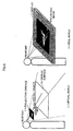
- FIG 5(b) shows an example of a display screen in the case where a relationship among the projection surface, the display surface, and the virtual object such as that shown in FIG 5(a) is assumed. If a relationship such as that shown in FIG 5(a) is assumed, that which is to be shown upon the display surface 116 in the real world is an enlarged image.
- a display region corresponding to the viewpoint position of the user is derived and image rendering is performed in that region.
- the display region corresponding to the position of the user viewpoint is also circular, and the position of the center thereof is determined in conformity with the following two parameters.
- the center of the display surface 116 is made the origin, the coordinate system having the center of display surface 116 as the origin is set as shown in FIG 6, with the viewpoint upon that coordinate system, the distance between the mask and the display surface, and the position of the center of the display region being defined as the following: (x eye , y eye , z eye ) viewpoint position d mask-display distance between mask and display surface (x center , y center , z center ) center position of display region
- the radius defining the magnitude of the circular display region 242 is derived from the following three parameters:
- the display has a rectangular shape with a width of 1360 mm and height of 1020 mm, and from the surface of the floor the height of the display surface is 1000 mm.
- the distance between the display mask and the display surface is 150 mm and the radius of the mask hole is 200 mm.
- the system of the embodiment described above is an example where the display surface is placed horizontally; alternatively, the display surface may naturally be placed vertically or at a slant. If the display is made to be the projection type, it is possible to achieve a large screen display. In addition, in order to configure a large display, a plurality of displays may be combined.
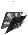
- FIG 8 shows a theatre-style multi-person shared three-dimensional display device capable of being used by multiple persons.
- the theatre style multi-person shared three-dimensional display device for example, given a width of 25 m, height of 18 m, distance of 6 m between the display mask and the display surface, radius of 0.5 m for the mask hole of the display mask, a maximum of forty-eight persons can simultaneously view the respective videos.
- the display mask is configured with liquid crystal, it is possible to control the radius, shape, and location of the hole of the display mask through the permeability and non-permeability of the liquid crystal.
- a mechanical mechanism such as an aperture mechanism or the like can be used.
- glasses with attached shutters are utilized wherein the opening and closing of the shutters is synchronized and images corresponding to the left/right line of sight are displayed to obtain a three-dimensional image; however, the present invention is not limited to this method for obtaining a three-dimensional view.
- a filter based on polarization or color may be used as the glasses to be worn to segregate images corresponding to the left and right lines of sight.
- FIG 9(a) audience members traveling aboard carts 421, 422, and 423, respectively, view a display 416 via a hole 418 in display mask 414.
- FIG 9(b) shows a configuration where a three-dimensional image displayed on a display 516 is viewed through a hole 518 in a display mask 514 while a plurality of audience members are moving about a central stage.
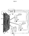
- FIG 10 An example of this configuration is shown in FIG 10.
- This configuration is a fundamentally similar configuration as the multi-person shared three-dimensional display device shown in FIG 1.
- sensors 162, 164, 166 are attached to each audience member and the respective position of each audience member is detected through a processing device 130.
- the processing device 130 in conformity with the detected positions, performs display corresponding to each person on the display regions 224, 226, 228 respectively associated with each audience member.
- the multi-person shared display device of the present invention it is possible to perform appropriate display corresponding to viewpoint movement for a plurality of persons.
- the relative positions between the viewpoint and projection surface in the virtual world are appropriately corrected corresponding to changes in the relative positions between the viewpoint and projection surface in the real world.
- a three-dimensional image can be displayed for a plurality of moving users having neither flickering nor spatial distortion.
- regions of viewpoint movement allowing a user to obtain an appropriate image have also been described in detail.
- the present invention is applicable to not only a stand-alone computer system, but may also be made applicable to, for example, a client server system or the like configured from a plurality of systems.
- Such storage media includes floppy disks, CD-ROMS, magnetic tape, and ROM cassettes.
- an image rendered upon a screen in compliance with the individual audience member positions is viewed via a hole of an appropriate size an appropriate distance from the screen.
- a hole of an appropriate size an appropriate distance from the screen.
- Technology relating to such a multi-person shared display device is capable of wide range industrial applicability, for example as a device for viewing three-dimensional objects.
Landscapes
- Engineering & Computer Science (AREA)
- Physics & Mathematics (AREA)
- General Physics & Mathematics (AREA)
- Multimedia (AREA)
- Signal Processing (AREA)
- Optics & Photonics (AREA)
- General Engineering & Computer Science (AREA)
- Theoretical Computer Science (AREA)
- Human Computer Interaction (AREA)
- Testing, Inspecting, Measuring Of Stereoscopic Televisions And Televisions (AREA)
- Controls And Circuits For Display Device (AREA)
- Stereoscopic And Panoramic Photography (AREA)
Abstract
Description

- Position of the viewpoint upon the display coordinate system
- Distance between the mask and the display surface
| (xeye, yeye, zeye) | viewpoint position |
| dmask-display | distance between mask and display surface |
| (xcenter, ycenter, zcenter) | center position of display region |
| rhole | radius of the hole on the mask |
| rdraw | radius of the display region |
Claims (5)
- A multi-person shared display device, which is a display device shared by a plurality of users, comprising:a display device, which displays a plurality of video for a plurality of users on a screen;a display mask, which is disposed so as to cover said display device separated by a fixed distance and has a sufficiently large hole;a position sensor, which detects a location of a user in real space corresponding to said display device; anda processing device, which is dynamically combined with said one display device and said position sensor, and displays an image corresponding to each user upon said display device in accordance with said position of the user through said position sensor.
- The multi-person shared display device according to Claim 1, wherein
said video to be displayed upon the display device includes video for three-dimensional viewing. - The multi-person shared display device according to Claim 2, wherein
each user wears a plurality of glasses for separating said video for three-dimensional viewing displayed into that for the right eye and that for the left eye; and
the plurality of video for three dimensional viewing shown on said display device, is images allowing separation between that for the right eye and that for the left eye through said plurality of glasses. - The multi-person shared display device according to Claim 3, wherein
said glasses are glasses in which shutters for the right eye and for the left eye open and close; and
said processing device is dynamically combined with said glasses. - The multi-person shared display device according to either Claim 3 or Claim 4, wherein
said glasses and said position sensor are formed as an integral unit.
Applications Claiming Priority (3)
| Application Number | Priority Date | Filing Date | Title |
|---|---|---|---|
| JP2000199240 | 2000-06-30 | ||
| JP2000199240 | 2000-06-30 | ||
| PCT/JP2001/005656 WO2002003124A1 (en) | 2000-06-30 | 2001-06-29 | Multiple sharing type display device |
Publications (3)
| Publication Number | Publication Date |
|---|---|
| EP1296173A1 true EP1296173A1 (en) | 2003-03-26 |
| EP1296173A4 EP1296173A4 (en) | 2008-04-09 |
| EP1296173B1 EP1296173B1 (en) | 2012-06-13 |
Family
ID=18697290
Family Applications (1)
| Application Number | Title | Priority Date | Filing Date |
|---|---|---|---|
| EP01945723A Expired - Lifetime EP1296173B1 (en) | 2000-06-30 | 2001-06-29 | Multiple sharing type display device |
Country Status (4)
| Country | Link |
|---|---|
| US (1) | US6965381B2 (en) |
| EP (1) | EP1296173B1 (en) |
| JP (1) | JP4616543B2 (en) |
| WO (1) | WO2002003124A1 (en) |
Cited By (1)
| Publication number | Priority date | Publication date | Assignee | Title |
|---|---|---|---|---|
| US8780178B2 (en) | 2009-12-18 | 2014-07-15 | Electronics And Telecommunications Research Institute | Device and method for displaying three-dimensional images using head tracking |
Families Citing this family (33)
| Publication number | Priority date | Publication date | Assignee | Title |
|---|---|---|---|---|
| US7070921B2 (en) | 2000-04-28 | 2006-07-04 | Molecular Devices Corporation | Molecular modification assays |
| JP2004364197A (en) * | 2003-06-06 | 2004-12-24 | Asahi Kasei Electronics Co Ltd | Sensor unit |
| US7538746B2 (en) * | 2004-07-23 | 2009-05-26 | Lockheed Martin Corporation | Direct ocular virtual 3D workspace |
| JP4664108B2 (en) * | 2005-03-31 | 2011-04-06 | 富士通株式会社 | Display device, display method, display program, and display system |
| US8466954B2 (en) * | 2006-04-03 | 2013-06-18 | Sony Computer Entertainment Inc. | Screen sharing method and apparatus |
| WO2008152183A1 (en) * | 2007-06-15 | 2008-12-18 | Fogscreen Inc. | Display screen based on particles carried in a fluid stream |
| GB0920754D0 (en) * | 2009-11-27 | 2010-01-13 | Compurants Ltd | Inamo big book 1 |
| US20110141246A1 (en) * | 2009-12-15 | 2011-06-16 | Justin Michael Schwartz | System and Method for Producing Stereoscopic Images |
| DE102010009737A1 (en) * | 2010-03-01 | 2011-09-01 | Institut für Rundfunktechnik GmbH | Method and arrangement for reproducing 3D image content |
| US9030536B2 (en) | 2010-06-04 | 2015-05-12 | At&T Intellectual Property I, Lp | Apparatus and method for presenting media content |
| US8640182B2 (en) | 2010-06-30 | 2014-01-28 | At&T Intellectual Property I, L.P. | Method for detecting a viewing apparatus |
| US9787974B2 (en) | 2010-06-30 | 2017-10-10 | At&T Intellectual Property I, L.P. | Method and apparatus for delivering media content |
| US8593574B2 (en) | 2010-06-30 | 2013-11-26 | At&T Intellectual Property I, L.P. | Apparatus and method for providing dimensional media content based on detected display capability |
| US8918831B2 (en) | 2010-07-06 | 2014-12-23 | At&T Intellectual Property I, Lp | Method and apparatus for managing a presentation of media content |
| US9049426B2 (en) | 2010-07-07 | 2015-06-02 | At&T Intellectual Property I, Lp | Apparatus and method for distributing three dimensional media content |
| US9032470B2 (en) | 2010-07-20 | 2015-05-12 | At&T Intellectual Property I, Lp | Apparatus for adapting a presentation of media content according to a position of a viewing apparatus |
| US9560406B2 (en) | 2010-07-20 | 2017-01-31 | At&T Intellectual Property I, L.P. | Method and apparatus for adapting a presentation of media content |
| US9232274B2 (en) | 2010-07-20 | 2016-01-05 | At&T Intellectual Property I, L.P. | Apparatus for adapting a presentation of media content to a requesting device |
| US8994716B2 (en) | 2010-08-02 | 2015-03-31 | At&T Intellectual Property I, Lp | Apparatus and method for providing media content |
| US8438502B2 (en) | 2010-08-25 | 2013-05-07 | At&T Intellectual Property I, L.P. | Apparatus for controlling three-dimensional images |
| US8947511B2 (en) | 2010-10-01 | 2015-02-03 | At&T Intellectual Property I, L.P. | Apparatus and method for presenting three-dimensional media content |
| US8619124B2 (en) * | 2010-10-14 | 2013-12-31 | Industrial Technology Research Institute | Video data processing systems and methods |
| US9602766B2 (en) | 2011-06-24 | 2017-03-21 | At&T Intellectual Property I, L.P. | Apparatus and method for presenting three dimensional objects with telepresence |
| US8947497B2 (en) | 2011-06-24 | 2015-02-03 | At&T Intellectual Property I, Lp | Apparatus and method for managing telepresence sessions |
| US9030522B2 (en) | 2011-06-24 | 2015-05-12 | At&T Intellectual Property I, Lp | Apparatus and method for providing media content |
| US9445046B2 (en) | 2011-06-24 | 2016-09-13 | At&T Intellectual Property I, L.P. | Apparatus and method for presenting media content with telepresence |
| US8587635B2 (en) | 2011-07-15 | 2013-11-19 | At&T Intellectual Property I, L.P. | Apparatus and method for providing media services with telepresence |
| KR20130075253A (en) * | 2011-12-27 | 2013-07-05 | 한국전자통신연구원 | Method and apparatus for displaying stereoscopic image contents using pixel mapping |
| KR102153743B1 (en) | 2013-11-01 | 2020-09-10 | 삼성디스플레이 주식회사 | Display device |
| US9712810B2 (en) * | 2015-06-03 | 2017-07-18 | Disney Enterprises, Inc. | Tracked automultiscopic 3D tabletop display |
| DE102017208936A1 (en) * | 2017-05-29 | 2018-11-29 | Audi Ag | Method for operating a virtual reality system and virtual reality system |
| US10922892B1 (en) | 2019-04-30 | 2021-02-16 | Splunk Inc. | Manipulation of virtual object position within a plane of an extended reality environment |
| CN117939106B (en) * | 2024-03-19 | 2024-05-24 | 成都工业学院 | A viewpoint planning component for stereoscopic display |
Family Cites Families (12)
| Publication number | Priority date | Publication date | Assignee | Title |
|---|---|---|---|---|
| US5521724A (en) * | 1993-11-15 | 1996-05-28 | Shires; Mark R. | Real-time automultiscopic 3D video display using holographic optical elements (HOEs) |
| JP3516774B2 (en) * | 1995-06-14 | 2004-04-05 | 三菱電機株式会社 | 3D image display device |
| JP2846856B2 (en) * | 1996-07-19 | 1999-01-13 | 三洋電機株式会社 | 3D image display device |
| JP3472068B2 (en) * | 1997-03-19 | 2003-12-02 | 株式会社国際電気通信基礎技術研究所 | 3D image display device |
| JP2001519126A (en) * | 1997-03-27 | 2001-10-16 | リットン・システムズ・インコーポレーテッド | Automatic stereoscopic projection system |
| US5993003A (en) * | 1997-03-27 | 1999-11-30 | Litton Systems, Inc. | Autostereo projection system |
| US6798390B1 (en) | 1997-08-29 | 2004-09-28 | Canon Kabushiki Kaisha | 3D image reconstructing apparatus and 3D object inputting apparatus |
| JP3403048B2 (en) | 1997-12-10 | 2003-05-06 | キヤノン株式会社 | Three-dimensional image reproducing device and three-dimensional subject information input device |
| DE19746764B4 (en) * | 1997-10-23 | 2006-09-14 | Siemens Ag | display unit |
| US6710920B1 (en) * | 1998-03-27 | 2004-03-23 | Sanyo Electric Co., Ltd | Stereoscopic display |
| US5926318A (en) * | 1998-04-06 | 1999-07-20 | Optimize Incorporated | Biocular viewing system with intermediate image planes for an electronic display device |
| GB2371878A (en) * | 1999-11-22 | 2002-08-07 | Sl3D Inc | Stereoscopic telescope with camera |
-
2001
- 2001-06-29 WO PCT/JP2001/005656 patent/WO2002003124A1/en not_active Ceased
- 2001-06-29 JP JP2002508131A patent/JP4616543B2/en not_active Expired - Fee Related
- 2001-06-29 US US10/069,718 patent/US6965381B2/en not_active Expired - Lifetime
- 2001-06-29 EP EP01945723A patent/EP1296173B1/en not_active Expired - Lifetime
Cited By (1)
| Publication number | Priority date | Publication date | Assignee | Title |
|---|---|---|---|---|
| US8780178B2 (en) | 2009-12-18 | 2014-07-15 | Electronics And Telecommunications Research Institute | Device and method for displaying three-dimensional images using head tracking |
Also Published As
| Publication number | Publication date |
|---|---|
| EP1296173B1 (en) | 2012-06-13 |
| US20030043146A1 (en) | 2003-03-06 |
| WO2002003124A1 (en) | 2002-01-10 |
| JP4616543B2 (en) | 2011-01-19 |
| US6965381B2 (en) | 2005-11-15 |
| EP1296173A4 (en) | 2008-04-09 |
Similar Documents
| Publication | Publication Date | Title |
|---|---|---|
| US6965381B2 (en) | Multi-person shared display device | |
| JPWO2002003124A1 (en) | Multi-person display device | |
| Kulik et al. | C1x6: a stereoscopic six-user display for co-located collaboration in shared virtual environments | |
| US6788274B2 (en) | Apparatus and method for displaying stereoscopic images | |
| KR970004916A (en) | A stereoscopic CG image generating apparatus and stereoscopic television apparatus | |
| JP4052357B2 (en) | Virtual environment experience display device | |
| US6239830B1 (en) | Displayer and method for displaying | |
| CN108769664B (en) | Naked eye 3D display method, device, equipment and medium based on human eye tracking | |
| JP4069550B2 (en) | Virtual environment experience display device | |
| JPH09238369A (en) | 3D image display device | |
| US12052410B2 (en) | Image processing device, image processing method, and image display system for generating common images and individual images for users with overlapping fields of view | |
| US12278943B2 (en) | Display device and display method therefor | |
| US6061084A (en) | Displayer and a method for displaying | |
| Naimark | Elements of real-space imaging: a proposed taxonomy | |
| Baker | Generating images for a time-multiplexed stereoscopic computer graphics system | |
| JP3425402B2 (en) | Apparatus and method for displaying stereoscopic image | |
| JP2007323093A (en) | Display device for virtual environment experience | |
| JP3088326B2 (en) | 3D image display device | |
| Kang Wei et al. | Three-dimensional scene navigation through anaglyphic panorama visualization | |
| Lipton | Future of autostereoscopic electronic displays | |
| US20140152783A1 (en) | Display device | |
| US10701345B2 (en) | System and method for generating a stereo pair of images of virtual objects | |
| Lacoche et al. | Dealing with frame cancellation for stereoscopic displays in 3d user interfaces | |
| Kurogi et al. | Scalable Autostereoscopic Display with Temporal Division Method. | |
| JP2003141573A (en) | Immersive display device and method |
Legal Events
| Date | Code | Title | Description |
|---|---|---|---|
| PUAI | Public reference made under article 153(3) epc to a published international application that has entered the european phase |
Free format text: ORIGINAL CODE: 0009012 |
|
| 17P | Request for examination filed |
Effective date: 20020322 |
|
| AK | Designated contracting states |
Kind code of ref document: A1 Designated state(s): AT BE CH CY DE DK ES FI FR GB GR IE IT LI LU MC NL PT SE TR |
|
| RBV | Designated contracting states (corrected) |
Designated state(s): BE DE FR GB |
|
| A4 | Supplementary search report drawn up and despatched |
Effective date: 20080307 |
|
| 17Q | First examination report despatched |
Effective date: 20080912 |
|
| REG | Reference to a national code |
Ref country code: DE Ref legal event code: R079 Ref document number: 60146704 Country of ref document: DE Free format text: PREVIOUS MAIN CLASS: G02B0027220000 Ipc: G06F0003010000 |
|
| GRAP | Despatch of communication of intention to grant a patent |
Free format text: ORIGINAL CODE: EPIDOSNIGR1 |
|
| RIC1 | Information provided on ipc code assigned before grant |
Ipc: H04N 13/04 20060101ALI20111202BHEP Ipc: G06F 3/01 20060101AFI20111202BHEP |
|
| GRAS | Grant fee paid |
Free format text: ORIGINAL CODE: EPIDOSNIGR3 |
|
| GRAA | (expected) grant |
Free format text: ORIGINAL CODE: 0009210 |
|
| AK | Designated contracting states |
Kind code of ref document: B1 Designated state(s): BE DE FR GB |
|
| REG | Reference to a national code |
Ref country code: GB Ref legal event code: FG4D |
|
| REG | Reference to a national code |
Ref country code: DE Ref legal event code: R096 Ref document number: 60146704 Country of ref document: DE Effective date: 20120809 |
|
| PLBE | No opposition filed within time limit |
Free format text: ORIGINAL CODE: 0009261 |
|
| STAA | Information on the status of an ep patent application or granted ep patent |
Free format text: STATUS: NO OPPOSITION FILED WITHIN TIME LIMIT |
|
| 26N | No opposition filed |
Effective date: 20130314 |
|
| REG | Reference to a national code |
Ref country code: DE Ref legal event code: R097 Ref document number: 60146704 Country of ref document: DE Effective date: 20130314 |
|
| REG | Reference to a national code |
Ref country code: FR Ref legal event code: PLFP Year of fee payment: 16 |
|
| REG | Reference to a national code |
Ref country code: FR Ref legal event code: PLFP Year of fee payment: 17 |
|
| REG | Reference to a national code |
Ref country code: FR Ref legal event code: PLFP Year of fee payment: 18 |
|
| PGFP | Annual fee paid to national office [announced via postgrant information from national office to epo] |
Ref country code: DE Payment date: 20180625 Year of fee payment: 18 |
|
| PGFP | Annual fee paid to national office [announced via postgrant information from national office to epo] |
Ref country code: FR Payment date: 20180620 Year of fee payment: 18 Ref country code: BE Payment date: 20180620 Year of fee payment: 18 |
|
| PGFP | Annual fee paid to national office [announced via postgrant information from national office to epo] |
Ref country code: GB Payment date: 20180620 Year of fee payment: 18 |
|
| REG | Reference to a national code |
Ref country code: DE Ref legal event code: R119 Ref document number: 60146704 Country of ref document: DE |
|
| GBPC | Gb: european patent ceased through non-payment of renewal fee |
Effective date: 20190629 |
|
| REG | Reference to a national code |
Ref country code: BE Ref legal event code: MM Effective date: 20190630 |
|
| PG25 | Lapsed in a contracting state [announced via postgrant information from national office to epo] |
Ref country code: DE Free format text: LAPSE BECAUSE OF NON-PAYMENT OF DUE FEES Effective date: 20200101 Ref country code: GB Free format text: LAPSE BECAUSE OF NON-PAYMENT OF DUE FEES Effective date: 20190629 |
|
| PG25 | Lapsed in a contracting state [announced via postgrant information from national office to epo] |
Ref country code: BE Free format text: LAPSE BECAUSE OF NON-PAYMENT OF DUE FEES Effective date: 20190630 |
|
| PG25 | Lapsed in a contracting state [announced via postgrant information from national office to epo] |
Ref country code: FR Free format text: LAPSE BECAUSE OF NON-PAYMENT OF DUE FEES Effective date: 20190630 |