EP1296066A2 - Ventileinrichtung - Google Patents
Ventileinrichtung Download PDFInfo
- Publication number
- EP1296066A2 EP1296066A2 EP02020283A EP02020283A EP1296066A2 EP 1296066 A2 EP1296066 A2 EP 1296066A2 EP 02020283 A EP02020283 A EP 02020283A EP 02020283 A EP02020283 A EP 02020283A EP 1296066 A2 EP1296066 A2 EP 1296066A2
- Authority
- EP
- European Patent Office
- Prior art keywords
- carrier material
- valve device
- microvalve
- valve
- micro
- Prior art date
- Legal status (The legal status is an assumption and is not a legal conclusion. Google has not performed a legal analysis and makes no representation as to the accuracy of the status listed.)
- Withdrawn
Links
- 239000000463 material Substances 0.000 claims abstract description 24
- 239000012876 carrier material Substances 0.000 claims description 106
- 239000012530 fluid Substances 0.000 claims description 30
- 239000004020 conductor Substances 0.000 claims description 23
- 229920001971 elastomer Polymers 0.000 claims description 8
- 239000004033 plastic Substances 0.000 claims description 5
- 229920003023 plastic Polymers 0.000 claims description 5
- 239000000806 elastomer Substances 0.000 claims description 3
- 230000005489 elastic deformation Effects 0.000 claims description 2
- 238000007789 sealing Methods 0.000 description 6
- 238000004519 manufacturing process Methods 0.000 description 3
- 238000000034 method Methods 0.000 description 3
- 239000000758 substrate Substances 0.000 description 3
- 230000006870 function Effects 0.000 description 2
- 230000036316 preload Effects 0.000 description 2
- XUIMIQQOPSSXEZ-UHFFFAOYSA-N Silicon Chemical compound [Si] XUIMIQQOPSSXEZ-UHFFFAOYSA-N 0.000 description 1
- 229910000639 Spring steel Inorganic materials 0.000 description 1
- 230000015572 biosynthetic process Effects 0.000 description 1
- 229910010293 ceramic material Inorganic materials 0.000 description 1
- 239000003795 chemical substances by application Substances 0.000 description 1
- 238000010276 construction Methods 0.000 description 1
- 239000013013 elastic material Substances 0.000 description 1
- 238000005516 engineering process Methods 0.000 description 1
- 238000005530 etching Methods 0.000 description 1
- 238000003780 insertion Methods 0.000 description 1
- 230000037431 insertion Effects 0.000 description 1
- 230000010354 integration Effects 0.000 description 1
- 239000002184 metal Substances 0.000 description 1
- 229910052710 silicon Inorganic materials 0.000 description 1
- 239000010703 silicon Substances 0.000 description 1
- 230000007704 transition Effects 0.000 description 1
Images


Classifications
-
- F—MECHANICAL ENGINEERING; LIGHTING; HEATING; WEAPONS; BLASTING
- F15—FLUID-PRESSURE ACTUATORS; HYDRAULICS OR PNEUMATICS IN GENERAL
- F15B—SYSTEMS ACTING BY MEANS OF FLUIDS IN GENERAL; FLUID-PRESSURE ACTUATORS, e.g. SERVOMOTORS; DETAILS OF FLUID-PRESSURE SYSTEMS, NOT OTHERWISE PROVIDED FOR
- F15B13/00—Details of servomotor systems ; Valves for servomotor systems
- F15B13/02—Fluid distribution or supply devices characterised by their adaptation to the control of servomotors
- F15B13/06—Fluid distribution or supply devices characterised by their adaptation to the control of servomotors for use with two or more servomotors
- F15B13/08—Assemblies of units, each for the control of a single servomotor only
- F15B13/0803—Modular units
- F15B13/0832—Modular valves
-
- F—MECHANICAL ENGINEERING; LIGHTING; HEATING; WEAPONS; BLASTING
- F15—FLUID-PRESSURE ACTUATORS; HYDRAULICS OR PNEUMATICS IN GENERAL
- F15B—SYSTEMS ACTING BY MEANS OF FLUIDS IN GENERAL; FLUID-PRESSURE ACTUATORS, e.g. SERVOMOTORS; DETAILS OF FLUID-PRESSURE SYSTEMS, NOT OTHERWISE PROVIDED FOR
- F15B13/00—Details of servomotor systems ; Valves for servomotor systems
- F15B13/02—Fluid distribution or supply devices characterised by their adaptation to the control of servomotors
- F15B13/04—Fluid distribution or supply devices characterised by their adaptation to the control of servomotors for use with a single servomotor
- F15B13/042—Fluid distribution or supply devices characterised by their adaptation to the control of servomotors for use with a single servomotor operated by fluid pressure
- F15B13/043—Fluid distribution or supply devices characterised by their adaptation to the control of servomotors for use with a single servomotor operated by fluid pressure with electrically-controlled pilot valves
- F15B13/0431—Fluid distribution or supply devices characterised by their adaptation to the control of servomotors for use with a single servomotor operated by fluid pressure with electrically-controlled pilot valves the electrical control resulting in an on-off function
-
- F—MECHANICAL ENGINEERING; LIGHTING; HEATING; WEAPONS; BLASTING
- F15—FLUID-PRESSURE ACTUATORS; HYDRAULICS OR PNEUMATICS IN GENERAL
- F15B—SYSTEMS ACTING BY MEANS OF FLUIDS IN GENERAL; FLUID-PRESSURE ACTUATORS, e.g. SERVOMOTORS; DETAILS OF FLUID-PRESSURE SYSTEMS, NOT OTHERWISE PROVIDED FOR
- F15B13/00—Details of servomotor systems ; Valves for servomotor systems
- F15B13/02—Fluid distribution or supply devices characterised by their adaptation to the control of servomotors
- F15B13/06—Fluid distribution or supply devices characterised by their adaptation to the control of servomotors for use with two or more servomotors
- F15B13/08—Assemblies of units, each for the control of a single servomotor only
- F15B13/0803—Modular units
- F15B13/0807—Manifolds
- F15B13/081—Laminated constructions
-
- F—MECHANICAL ENGINEERING; LIGHTING; HEATING; WEAPONS; BLASTING
- F15—FLUID-PRESSURE ACTUATORS; HYDRAULICS OR PNEUMATICS IN GENERAL
- F15B—SYSTEMS ACTING BY MEANS OF FLUIDS IN GENERAL; FLUID-PRESSURE ACTUATORS, e.g. SERVOMOTORS; DETAILS OF FLUID-PRESSURE SYSTEMS, NOT OTHERWISE PROVIDED FOR
- F15B13/00—Details of servomotor systems ; Valves for servomotor systems
- F15B13/02—Fluid distribution or supply devices characterised by their adaptation to the control of servomotors
- F15B13/06—Fluid distribution or supply devices characterised by their adaptation to the control of servomotors for use with two or more servomotors
- F15B13/08—Assemblies of units, each for the control of a single servomotor only
- F15B13/0803—Modular units
- F15B13/0807—Manifolds
- F15B13/0814—Monoblock manifolds
-
- F—MECHANICAL ENGINEERING; LIGHTING; HEATING; WEAPONS; BLASTING
- F15—FLUID-PRESSURE ACTUATORS; HYDRAULICS OR PNEUMATICS IN GENERAL
- F15B—SYSTEMS ACTING BY MEANS OF FLUIDS IN GENERAL; FLUID-PRESSURE ACTUATORS, e.g. SERVOMOTORS; DETAILS OF FLUID-PRESSURE SYSTEMS, NOT OTHERWISE PROVIDED FOR
- F15B13/00—Details of servomotor systems ; Valves for servomotor systems
- F15B13/02—Fluid distribution or supply devices characterised by their adaptation to the control of servomotors
- F15B13/06—Fluid distribution or supply devices characterised by their adaptation to the control of servomotors for use with two or more servomotors
- F15B13/08—Assemblies of units, each for the control of a single servomotor only
- F15B13/0803—Modular units
- F15B13/0846—Electrical details
- F15B13/0853—Electric circuit boards
-
- F—MECHANICAL ENGINEERING; LIGHTING; HEATING; WEAPONS; BLASTING
- F15—FLUID-PRESSURE ACTUATORS; HYDRAULICS OR PNEUMATICS IN GENERAL
- F15B—SYSTEMS ACTING BY MEANS OF FLUIDS IN GENERAL; FLUID-PRESSURE ACTUATORS, e.g. SERVOMOTORS; DETAILS OF FLUID-PRESSURE SYSTEMS, NOT OTHERWISE PROVIDED FOR
- F15B13/00—Details of servomotor systems ; Valves for servomotor systems
- F15B13/02—Fluid distribution or supply devices characterised by their adaptation to the control of servomotors
- F15B13/06—Fluid distribution or supply devices characterised by their adaptation to the control of servomotors for use with two or more servomotors
- F15B13/08—Assemblies of units, each for the control of a single servomotor only
- F15B13/0803—Modular units
- F15B13/0846—Electrical details
- F15B13/0857—Electrical connecting means, e.g. plugs, sockets
-
- F—MECHANICAL ENGINEERING; LIGHTING; HEATING; WEAPONS; BLASTING
- F15—FLUID-PRESSURE ACTUATORS; HYDRAULICS OR PNEUMATICS IN GENERAL
- F15B—SYSTEMS ACTING BY MEANS OF FLUIDS IN GENERAL; FLUID-PRESSURE ACTUATORS, e.g. SERVOMOTORS; DETAILS OF FLUID-PRESSURE SYSTEMS, NOT OTHERWISE PROVIDED FOR
- F15B13/00—Details of servomotor systems ; Valves for servomotor systems
- F15B13/02—Fluid distribution or supply devices characterised by their adaptation to the control of servomotors
- F15B13/06—Fluid distribution or supply devices characterised by their adaptation to the control of servomotors for use with two or more servomotors
- F15B13/08—Assemblies of units, each for the control of a single servomotor only
- F15B13/0803—Modular units
- F15B13/0875—Channels for electrical components, e.g. for cables or sensors
-
- F—MECHANICAL ENGINEERING; LIGHTING; HEATING; WEAPONS; BLASTING
- F15—FLUID-PRESSURE ACTUATORS; HYDRAULICS OR PNEUMATICS IN GENERAL
- F15B—SYSTEMS ACTING BY MEANS OF FLUIDS IN GENERAL; FLUID-PRESSURE ACTUATORS, e.g. SERVOMOTORS; DETAILS OF FLUID-PRESSURE SYSTEMS, NOT OTHERWISE PROVIDED FOR
- F15B13/00—Details of servomotor systems ; Valves for servomotor systems
- F15B13/02—Fluid distribution or supply devices characterised by their adaptation to the control of servomotors
- F15B13/06—Fluid distribution or supply devices characterised by their adaptation to the control of servomotors for use with two or more servomotors
- F15B13/08—Assemblies of units, each for the control of a single servomotor only
- F15B13/0803—Modular units
- F15B13/0878—Assembly of modular units
- F15B13/0896—Assembly of modular units using different types or sizes of valves
-
- F—MECHANICAL ENGINEERING; LIGHTING; HEATING; WEAPONS; BLASTING
- F15—FLUID-PRESSURE ACTUATORS; HYDRAULICS OR PNEUMATICS IN GENERAL
- F15C—FLUID-CIRCUIT ELEMENTS PREDOMINANTLY USED FOR COMPUTING OR CONTROL PURPOSES
- F15C5/00—Manufacture of fluid circuit elements; Manufacture of assemblages of such elements integrated circuits
-
- F—MECHANICAL ENGINEERING; LIGHTING; HEATING; WEAPONS; BLASTING
- F16—ENGINEERING ELEMENTS AND UNITS; GENERAL MEASURES FOR PRODUCING AND MAINTAINING EFFECTIVE FUNCTIONING OF MACHINES OR INSTALLATIONS; THERMAL INSULATION IN GENERAL
- F16K—VALVES; TAPS; COCKS; ACTUATING-FLOATS; DEVICES FOR VENTING OR AERATING
- F16K99/00—Subject matter not provided for in other groups of this subclass
- F16K99/0001—Microvalves
-
- F—MECHANICAL ENGINEERING; LIGHTING; HEATING; WEAPONS; BLASTING
- F16—ENGINEERING ELEMENTS AND UNITS; GENERAL MEASURES FOR PRODUCING AND MAINTAINING EFFECTIVE FUNCTIONING OF MACHINES OR INSTALLATIONS; THERMAL INSULATION IN GENERAL
- F16K—VALVES; TAPS; COCKS; ACTUATING-FLOATS; DEVICES FOR VENTING OR AERATING
- F16K99/00—Subject matter not provided for in other groups of this subclass
- F16K99/0001—Microvalves
- F16K99/0034—Operating means specially adapted for microvalves
- F16K99/0042—Electric operating means therefor
- F16K99/0048—Electric operating means therefor using piezoelectric means
-
- F—MECHANICAL ENGINEERING; LIGHTING; HEATING; WEAPONS; BLASTING
- F16—ENGINEERING ELEMENTS AND UNITS; GENERAL MEASURES FOR PRODUCING AND MAINTAINING EFFECTIVE FUNCTIONING OF MACHINES OR INSTALLATIONS; THERMAL INSULATION IN GENERAL
- F16K—VALVES; TAPS; COCKS; ACTUATING-FLOATS; DEVICES FOR VENTING OR AERATING
- F16K99/00—Subject matter not provided for in other groups of this subclass
- F16K99/0001—Microvalves
- F16K99/0034—Operating means specially adapted for microvalves
- F16K99/0042—Electric operating means therefor
- F16K99/0053—Electric operating means therefor using magnetostrictive means
-
- F—MECHANICAL ENGINEERING; LIGHTING; HEATING; WEAPONS; BLASTING
- F16—ENGINEERING ELEMENTS AND UNITS; GENERAL MEASURES FOR PRODUCING AND MAINTAINING EFFECTIVE FUNCTIONING OF MACHINES OR INSTALLATIONS; THERMAL INSULATION IN GENERAL
- F16K—VALVES; TAPS; COCKS; ACTUATING-FLOATS; DEVICES FOR VENTING OR AERATING
- F16K99/00—Subject matter not provided for in other groups of this subclass
- F16K2099/0073—Fabrication methods specifically adapted for microvalves
- F16K2099/0076—Fabrication methods specifically adapted for microvalves using electrical discharge machining [EDM], milling or drilling
-
- F—MECHANICAL ENGINEERING; LIGHTING; HEATING; WEAPONS; BLASTING
- F16—ENGINEERING ELEMENTS AND UNITS; GENERAL MEASURES FOR PRODUCING AND MAINTAINING EFFECTIVE FUNCTIONING OF MACHINES OR INSTALLATIONS; THERMAL INSULATION IN GENERAL
- F16K—VALVES; TAPS; COCKS; ACTUATING-FLOATS; DEVICES FOR VENTING OR AERATING
- F16K99/00—Subject matter not provided for in other groups of this subclass
- F16K2099/0073—Fabrication methods specifically adapted for microvalves
- F16K2099/0078—Fabrication methods specifically adapted for microvalves using moulding or stamping
-
- F—MECHANICAL ENGINEERING; LIGHTING; HEATING; WEAPONS; BLASTING
- F16—ENGINEERING ELEMENTS AND UNITS; GENERAL MEASURES FOR PRODUCING AND MAINTAINING EFFECTIVE FUNCTIONING OF MACHINES OR INSTALLATIONS; THERMAL INSULATION IN GENERAL
- F16K—VALVES; TAPS; COCKS; ACTUATING-FLOATS; DEVICES FOR VENTING OR AERATING
- F16K99/00—Subject matter not provided for in other groups of this subclass
- F16K2099/0073—Fabrication methods specifically adapted for microvalves
- F16K2099/008—Multi-layer fabrications
-
- Y—GENERAL TAGGING OF NEW TECHNOLOGICAL DEVELOPMENTS; GENERAL TAGGING OF CROSS-SECTIONAL TECHNOLOGIES SPANNING OVER SEVERAL SECTIONS OF THE IPC; TECHNICAL SUBJECTS COVERED BY FORMER USPC CROSS-REFERENCE ART COLLECTIONS [XRACs] AND DIGESTS
- Y10—TECHNICAL SUBJECTS COVERED BY FORMER USPC
- Y10T—TECHNICAL SUBJECTS COVERED BY FORMER US CLASSIFICATION
- Y10T137/00—Fluid handling
- Y10T137/7504—Removable valve head and seat unit
Definitions
- the invention relates to a valve device, with at least a micro valve that is fixed to a support structure.
- valve device In a valve device known from US 5640995 this Type are multiple micro valves on one of several Layers of existing support structure attached.
- the support structure consists for example of printed circuit board material or ceramic materials.
- the micro valves on the surface of a PCB attached In doing so, the flatness and freedom from distortion the circuit board made very high demands. The effort for the manufacture and assembly of the valve device is therefore relatively large.
- the microvalve for fixing it between the rubber-elastic carrier material the support structure is clamped.
- the attachment of one or more micro valves to a support structure thus takes place by clamping between the carrier material, which has rubber-elastic properties.
- carrier material is capable of sufficient Holding forces for securely fixing the micro valve in question build.
- it can depend on the shape of the Automatically adjust the microvalve so that even larger manufacturing tolerances be easily compensated for what the Manufacturing and assembly simplified.
- rubber elasticity of the carrier material also mechanical Decoupling of the microvalve from the environment can be achieved; Impacts introduced into the carrier material strain the structure of the microvalve at most to a small extent.
- the carrier material Rubber or elastomer plastic in question, being a foam-like Construction is possible.
- the carrier material consist of one and the same material or can be made of different materials.
- the carrier material it is particularly expedient to use at least the carrier material to provide a recess forming a pocket, in which a micro valve is plugged in.
- the bag is preferred dimensioned so that the carrier material from the inserted Micro valve is deformed elastically and the micro valve thereby acting on it. When inserting the microvalve is simply pushed into the pocket and is then held securely, largely by friction.
- microvalve between to clamp two separate rubber-elastic carrier material layers.
- the microvalve is between two Carrier material layers placed, which are then replaced by suitable Acting means from opposite sides biased against the micro valve.
- suitable Acting means from opposite sides biased against the micro valve.
- the microvalve can be completely enclosed by the carrier material his.
- the holding force causing the microvalve to clamp also be delivered exclusively from the carrier material itself, that deforms elastically when the microvalve is installed is so that a restoring force of the carrier material on the Micro valve acts.
- valve device is equipped with actuating means is expediently contain two plate-like trained admission body, between which the carrier material is located and by suitable Clamping devices from opposite sides against the carrier material are biased.
- the clamping means work expediently immediately between the admission bodies and can, for example, of hooking means and / or of be elastic clips formed.
- At least in the carrier material can provide electrical conductors leading a microvalve.
- This electrical Conductors and / or fluid channels are expediently already before installing the at least one microvalve in the Carrier material realized and lead there to the various Places where a microvalve is placed.
- the respectively installed micro valve directly with the ones structured into the carrier material Fluid channels communicates, the carrier material itself performs the required sealing function.
- Direct electrical contact can also be made of the microvalve.
- fluid channels can be a function-specific Recommend material selection of the carrier material.
- the carrier material For example can be used on the electrical contact Side of the microvalve carrier material from an electrical conductive structured material are used while on the opposite for the fluidic connection A material is selected on the side of the microvalve, which has particularly good sealing properties.
- the rubber-elastic properties of the carrier material can also allow the external shape to adapt to local Conditions to vary without the integration of the micro valves to affect.
- Valve devices are each with one or more Micro valves 2 equipped. Regardless of the specific embodiment can those equipped with only one microvalve 2 Valve devices 1 also a plurality of micro valves 2 included, and vice versa.
- the micro valves 2 are independent complete valves that have a valve housing 3 in which at least one movable Valve member 4 is housed. Depending on the momentary switching position of the valve member 4 results in a Release and / or interruption of a fluidic connection between several valve channels 5.
- the in the embodiments provided micro valves 2 have a 2/2 valve functionality, albeit of a higher quality Functionalities would be possible, for example by type called 3/2-way valves.
- Each microvalve 2 is equipped with drive means 6, through which the switching position of the valve member 4 are determined leaves. It is expediently electrical activatable drive means 6, as in the embodiment the case is.
- the drive means 6 can for example based on electrostatic principle.
- valve channels 5 open with valve channel openings 7 to the outer surface of the valve housing 3. All valve channel openings 7 are conveniently located on the same Housing outer surface, hereinafter referred to as the first housing outer surface 8 is referred to.
- the drive means 6 have electrical contact means 12 for feeding the electrical actuation signals. Also they are led to the outer surface of the valve housing 3, where they end with first electrical contact surfaces 13. Prefers all first electrical contact surfaces 13 are on and the same outer housing surface arranged below be referred to as the second housing outer surface 9. The first and second housing outer surfaces 8, 9 are expediently on opposite sides of the valve housing Third
- the microvalves 2 preferably have a micromechanical structured structure. You can use it the method known from micro-system technology , for example using a silicon etching technique or a plastic impression process. In addition to the functional principle already mentioned, for example also a piezoelectric, a magnetostrictive or a Functional principle of memory metal conceivable.
- microvalves 2 can be used sensibly, it needs to be fixed to a generally with reference number 14 designated support structure. This is done via this support structure the mechanical, electrical and fluidic connection to the macro environment of the respective micro valve.
- the supporting structure 14 can thus be used, for example, to create a to fix several micro valves 2 on site, the required transmit electrical signals and fluid exchange to allow.
- the support structure contains 14 rubber-elastic carrier material 15, between which the Micro valve 2 concerned is firmly clamped. It is alone this restraint in the rubber-elastic properties available carrier material 15, which is the attachment of the microvalve 2 causes. In particular, it is not a direct connection to a rigid support material, as is the case with State of the art is usually the case.
- the carrier material 15 suitably consists of rubber or an elastomer plastic. For particularly high flexibility can get a foam-like structure with air-filled cavities are provided.
- the microvalve is seated 2 in an open to the outer surface of the carrier material 15 Well that can be called pocket 16. at assembly, the microvalve 2 is simply placed in the pocket 16 inserted, as illustrated by the arrow 17 in FIG. 2 becomes.
- the dimensions of the pocket 16 are expediently chosen so that that regarding the outside dimensions of the microvalve there is a certain undersize and therefore the microvalve 2 with plug-in assembly with a certain amount of effort in the pocket 16 is to be pressed.
- the carrier material 15 elastically deformed, the resulting Resilience of the rubber-elastic material for fixing of the microvalve 2 provides the required holding force.
- the caused by the elastic deformation of the carrier material 15 Holding force can be the only holding force that acts on the microvalve 2.
- the configuration can be such that the microvalve 2 alone in the press fit, by the resulting Frictional forces is held in the pocket 16.
- measures that additionally include a cause positive fixation.
- valve device 1 shown in FIG. 3 corresponds that of FIGS. 1 and 2, with the difference that of the same rubber-elastic carrier material 15 at the same time several micro valves 2 are held.
- carrier material 15 are several pockets 16 in any arrangement formed, in each of which a microvalve 2 is inserted.
- the structure of the valve device 1 according to FIG. 5 corresponds in principle that of FIG. 3, but with the support structure 14 additionally a support body 18 with a curved Has wing 19 on which the carrier material 15 is placed is.
- the rubber-elastic carrier material is evident 15 able to match its outer shape to the shape of the wing 19 to adapt.
- the valve device can thus if necessary mounted on spatially curved wings become.
- the carrier body 18 can also have a flat wing, for example around a flat outer surface Place the carrier material 15 on it, as in the case of the valve device 1 of FIGS. 1 and 2 is the case.
- the carrier material 15 can, for example, with the carrier body 18 be glued.
- the carrier body 18 can also be an independent body, which does not belong to the supporting structure 14 and which, for example is provided on a fluid power device that with a valve device 1 is to be equipped.
- the carrier material 15 is here expediently from a uniform material.
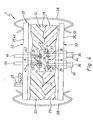
- the carrier material has a layer structure can. It consists in particular of several, surface-mounted Carrier material layers 22 together, wherein the micro valves 2 within at least one and preferably arranged within one and the same carrier material layer 22a are.
- the microvalve 2 with carrier material layers still separated from one another 23 at the designated place of the one Carrier material layer 23 are placed, followed by the opposite side the other carrier material layer 23 is set and finally the two layers of support material 23 only from opposite sides with the Micro valve 2 must be clamped.
- the dimensions of the carrier material layers 23 can for example be chosen so that they laterally over the Micro valve 2 does not protrude or only slightly. In the 4 a larger extension is selected, so that the carrier material layers 23 are mutual Bias around the micro valve 2 and a flat contact between the carrier material layers 23 takes place around the microvalve 2.
- the contact area of the carrier material layers marked at 24 in FIG. 4 23 can be flat or uneven, in Dependence on the initial design of the facing one another Surfaces of the carrier material layers 23.
- the micro valve 2 is of the carrier material 15 completely enclosed, there is a particularly effective Protection against external influences.
- the micro valve 2 is safe embedded in the rubber-elastic carrier material 15.
- the possibility of opening the pockets 16 after Plug a micro valve 2 to close for example can be provided a cover that is Fix in the pocket 16 similar to a plug leaves. With such a design, it is then in the direction of insertion of the microvalve 2 measured depth of the pocket larger selected as the corresponding measured length of the microvalve 2, so that when the microvalve is fully inserted 2 in the area of the pocket opening there remains an area which can at least partially accommodate the cover.
- the loading means 25 can two preferably plate-shaped first and second loading bodies 26, 27 included, between which the carrier material 15 is sandwiched.
- the expansion planes the loading body 26, 27 run expediently parallel to those of the assigned Carrier material layers 22, 23.
- the outline of the loading body 26, 27 is expedient designed so that the entire outline of the substrate layers 23 is covered.
- the loading means 25 also contain suitable ones Clamping means 28 with which the two loading bodies 26, 27 are pulled against each other so that they are of opposite Pages biased against the carrier material 15 are and the microvalves 2 a firm, yet elastic experience flexible clamping.
- the clamping means 28 formed by resilient brackets, the distance between bridge the two loading bodies 26, 27 and against the outer surfaces 32 of the application bodies facing away from one another 26, 27 are biased.
- the resilient Brackets are made of spring steel, for example and can have a bow-like shape.
- the clamping means 28 formed by interlocking means on both bodies 26, 27 are fixed and in one position reach behind, in which the loading body 26, 27 are so close to each other that the desired clamping intensity of the carrier material 15 is given.
- connection body 33 which is equipped with connection means 34 which are not shown fluid lines, for example Have fluid hoses connected.
- connection means 34 can be used as connector devices be designed.
- connection means 34 communicate with at least each a fluid channel 35 which passes through the carrier material 15 and leads to at least one microvalve 2.
- the fluid channels 35 provide the fluid connection between the in the carrier material 15th embedded micro valves 2 and accessible from the outside Connection openings 36 forth, wherein the connection openings 36 4 and 6 of the connection means in the exemplary embodiments of FIGS 34 are defined.
- Fluid channels 35 are provided, although not in all figures are shown. As can be seen from Fig. 1, the connection openings 36 in the absence of a connector body 33 also directly from the end portion of the to an outer surface of the carrier material 15 opening fluid channels 35 are formed his.
- the fluid channels provided for connection to a microvalve 2 35 each end with a fluid channel opening 37 that surface section of the carrier material 15 which the microvalve 2 in the clamped state with the first Housing outer surface 8 comes to rest.
- the arrangement is like this met that with the microvalve 2 installed, the valve channel openings 7 and the fluid channel orifices 37 lie opposite one another in pairs.
- the carrier material 15 with its Fluid channel openings 37 surrounding material areas 38 sealing around the associated valve channel mouth 37 around is applied to the microvalve 2, a very reliable result sealed fluid connection. Because the direction of force with which the carrier material 15 is biased against the microvalve 2 is, with the axial direction of the channel mouths 7, 37 expediently coincides, is by tightening provided the required sealing force at the same time.
- the multilayer structure is used of the carrier material 15 also very flexible Fluid channel courses between the connection openings 36 and the micro valves 2 or between different To realize micro valves 2.
- Multiple layers of substrate 22b, 22c, 22d contain internal lengths of the fluid channels 35, which are in the case of attached carrier material layers add to the desired channel course.
- Corresponding the complexity of the desired fluidic connection can be the number of corresponding substrate layers can be varied.
- the mutual sealing on the channel transitions aligned with one another can thereby be achieved directly be guaranteed to be a rubber elastic Backing material with sealing properties used.
- valve device 1 with both hydraulic media and gaseous Media, especially with compressed air.
- Electrical conductors 42 run in the carrier material 15, via the electric drive means 6 of the microvalves 2 the electrical actuation signals required for actuation can be transmitted.
- the electrical conductors 42 are in the embodiment of with respect to the carrier material 15 separate conductor elements formed that Push through carrier material 15.
- the electrical conductor 42 starting from a preferably plate-like trained contact body 43, here in Unit formed with the second loading body 27 is.
- Electrical contact means are on the contacting body 43 44 provided the feeding of the electrical Enable actuation signals and as part of electrical conductor 42 can be executed.
- the electrical contacting means 44 directly from those protruding from the carrier material 15 End portions of the electrical conductor 42 are formed his.
- the contacting body 43 can with electrical if necessary and electronic components 45, which are for the electrical control of the micro valves 2 are required. They stand in a suitable manner with the necessary electrical Conductors 42 in connection.
- the contacting body is 43 a circuit board.
- the electrical contact between the electrical conductors 42 of the carrier material 15 and the electrical contact means 12 of the microvalves 2 is advantageously carried out alone due to positive contact without plug connection measures. 1 and 4 open the electrical Conductor 42, each with an end second electrical contact surface 45 to that surface section of the carrier material 15, that of the second housing outer surface 9 of the microvalve 2 faces.
- the arrangement is so that there are first and second electrical contact surfaces 13, 45 in pairs opposite each other and with preload abut each other. This way when assembling the microvalves 2 not only the fluid ones, but also the electrical connections are made.
- the Fluid channels 35 in one and electrical conductors 42 in of the other carrier material layer 23 are formed.
- the materials for the Select carrier material 15 function-specifically.
- the carrier material layer containing the fluid channels 35 23 for optimal fluid-tight properties are selected, and the one containing the electrical conductors 42
- Carrier material layer 23 can be made, for example, of electrical conductive structured material are produced, to provide an integral design of the electrical conductors 42 enable.
- the electrical conductors can both from in Carrier material 15 embedded conductor elements and / or of electrically conductive material regions of the carrier material 15 be formed, the latter for example using anisotropic conductive plastics.
Landscapes
- Engineering & Computer Science (AREA)
- General Engineering & Computer Science (AREA)
- Mechanical Engineering (AREA)
- Physics & Mathematics (AREA)
- Fluid Mechanics (AREA)
- Chemical & Material Sciences (AREA)
- Dispersion Chemistry (AREA)
- Computer Hardware Design (AREA)
- Microelectronics & Electronic Packaging (AREA)
- Theoretical Computer Science (AREA)
- Check Valves (AREA)
- Micromachines (AREA)
Abstract
Description
- Fig. 1
- eine mit lediglich einem Mikroventil ausgestattete Ventileinrichtung, teilweise geschnitten,
- Fig. 2
- einen Ausschnitt der Ventileinrichtung aus Fig. 1 zur Verdeutlichung der Montage des Mikroventils,
- Fig. 3
- eine Draufsicht auf eine weitere Ausführungsform der Ventileinrichtung, die mit mehreren Mikroventilen ausgestattet ist,
- Fig. 4
- eine weitere Ausführungsform der Ventileinrichtung, bei der ein Mikroventil zwischen zwei separaten gummielastischen Trägermaterialschichten eingespannt ist,
- Fig. 5
- eine weitere Ausführungsform der Ventileinrichtung, aus der die Gestaltungsflexibilität des Trägermaterials hervorgeht, und
- Fig. 6
- einen Längsschnitt durch eine weitere Bauform der erfindungsgemäßen Ventileinrichtung, deren Trägermaterial einen Mehrschichtaufbau besitzt.
Claims (20)
- Ventileinrichtung, mit mindestens einem Mikroventil (2), das an einer Trägerstruktur (14) fixiert ist, dadurch gekennzeichnet, dass das Mikroventil (2) zu seiner Fixierung zwischen gummielastischem Trägermaterial (15) der Trägerstruktur (14) eingespannt ist.
- Ventileinrichtung nach Anspruch 1, dadurch gekennzeichnet, dass mindestens ein Mikroventil (2) in eine Tasche (16) des Trägermaterials (15) eingesteckt ist.
- Ventileinrichtung nach Anspruch 2, dadurch gekennzeichnet, dass die Tasche (16) so dimensioniert ist, dass das Trägermaterial (15) vom eingesteckten Mikroventil (2) elastisch verformt wird und das Mikroventil (2) dadurch haltend beaufschlagt wird.
- Ventileinrichtung nach einem der Ansprüche 1 bis 3, dadurch gekennzeichnet, dass mindestens ein Mikroventil (2) zwischen zwei separaten gummielastischen Trägermaterialschichten (23) eingespannt ist.
- Ventileinrichtung nach einem der Ansprüche 1 bis 4, dadurch gekennzeichnet, dass die das Festspannen mindestens eines Mikroventils bewirkenden Haltekräfte ausschließlich von der bei der Montage des Mikroventils hervorgerufenen elastischen Verformung des Trägermaterials (15) herrühren.
- Ventileinrichtung nach einem der Ansprüche 1 bis 4, gekennzeichnet durch Beaufschlagungsmittel (25) zum Beaufschlagen des Trägermaterials (15) zum Zwecke des Hervorrufens mindestens ein Mikroventil festspannender Haltekräfte.
- Ventileinrichtung nach Anspruch 6, dadurch gekennzeichnet, dass die Beaufschlagungsmittel (25) zwei vorzugsweise plattenartig ausgebildete Beaufschlagungskörper (26, 27) enthalten, zwischen denen das Trägermaterial (15) angeordnet ist und die von entgegengesetzten Seiten her gegen das Trägermaterial (15) vorgespannt sind.
- Ventileinrichtung nach Anspruch 7, gekennzeichnet durch Spannmittel (28) zum gegenseitigen Verspannen der Beaufschlagungskörper (26, 27).
- Ventileinrichtung nach Anspruch 8, dadurch gekennzeichnet, dass die Spannmittel (28) Verhakungsmittel und/oder mindestens eine federelastische Klammer aufweisen.
- Ventileinrichtung nach einem der Ansprüche 1 bis 9, dadurch gekennzeichnet, dass in dem Trägermaterial (15) zu dem mindestens einen Mikroventil (2) führende elektrische Leiter (42) verlaufen, die zweckmäßigerweise allein durch Berührkontakt an das betreffende Mikroventil (2) angeschlossen sind.
- Ventileinrichtung nach Anspruch 10, dadurch gekennzeichnet, dass die elektrischen Leiter (42) von in das Trägermaterial (15) eingebetteten Leiterelementen und/oder von elektrisch leitenden Materialbereichen des Trägermaterials (15) gebildet sind.
- Ventileinrichtung nach Anspruch 10 oder 11, dadurch gekennzeichnet, dass die elektrischen Leiter (42) zumindest teilweise zu einem an das Trägermaterial (15) angesetzten und vorzugsweise plattenartig ausgebildeten Kontaktierungskörper (43) führen, der zweckmäßigerweise von einer Leiterplatte gebildet ist.
- Ventileinrichtung nach einem der Ansprüche 1 bis 12, dadurch gekennzeichnet, dass in dem Trägermaterial (15) zu dem mindestens einen Mikroventil (2) führende Fluidkanäle (35) verlaufen.
- Ventileinrichtung nach Anspruch 13, dadurch gekennzeichnet, dass die Fluidverbindung zwischen den Fluidkanälen (35) und dem zugeordneten Mikroventil (2) zumindest teilweise dadurch realisiert ist, dass das Trägermaterial (15) mit die betreffende Fluidkanalmündung (37) umschließenden Materialbereichen (38) dichtend am Mikroventil (2) anliegt.
- Ventileinrichtung nach Anspruch 13 oder 14, dadurch gekennzeichnet, dass die Fluidkanäle (35) zumindest teilweise zu einem an das Trägermaterial (15) angesetzten und vorzugsweise plattenartig ausgebildeten Anschlusskörper (33) führen, der zweckmäßigerweise mit Anschlussmitteln (34) für Fluidleitungen ausgestattet ist.
- Ventileinrichtung nach einem der Ansprüche 1 bis 15, dadurch gekennzeichnet, dass das Trägermaterial (15) mehrere, flächig aneinandergesetzte Trägermaterialschichten (22) aufweist, in denen miteinander kommunizierende Fluidkanalabschnitte verlaufen.
- Ventileinrichtung nach einem der Ansprüche 12 bis 16 in Verbindung mit Anspruch 7, dadurch gekennzeichnet, dass der Kontaktierungskörper (43) und/oder der Anschlusskörper (33) gleichzeitig einen Beaufschlagungskörper (26, 27) der Beaufschlagungsmittel (25) bildet.
- Ventileinrichtung nach einem der Ansprüche 1 bis 17, dadurch gekennzeichnet, dass das Trägermaterial (15) aus wenigstens zwei unterschiedlichen Werkstoffen besteht.
- Ventileinrichtung nach einem der Ansprüche 1 bis 18, dadurch gekennzeichnet, dass das Trägermaterial (15) aus Gummi oder aus einem Elastomer-Kunststoff besteht.
- Ventileinrichtung nach einem der Ansprüche 1 bis 19, gekennzeichnet durch mehrere, vom gleichen gummielastischen Trägermaterial (15) gehaltene Mikroventile (2).
Applications Claiming Priority (2)
| Application Number | Priority Date | Filing Date | Title |
|---|---|---|---|
| DE20115733U DE20115733U1 (de) | 2001-09-25 | 2001-09-25 | Ventileinrichtung |
| DE20115733U | 2001-09-25 |
Publications (2)
| Publication Number | Publication Date |
|---|---|
| EP1296066A2 true EP1296066A2 (de) | 2003-03-26 |
| EP1296066A3 EP1296066A3 (de) | 2006-05-31 |
Family
ID=7962091
Family Applications (1)
| Application Number | Title | Priority Date | Filing Date |
|---|---|---|---|
| EP02020283A Withdrawn EP1296066A3 (de) | 2001-09-25 | 2002-09-11 | Ventileinrichtung |
Country Status (3)
| Country | Link |
|---|---|
| US (1) | US6866060B2 (de) |
| EP (1) | EP1296066A3 (de) |
| DE (1) | DE20115733U1 (de) |
Families Citing this family (2)
| Publication number | Priority date | Publication date | Assignee | Title |
|---|---|---|---|---|
| DE10243699B4 (de) * | 2002-09-20 | 2005-01-05 | Festo Ag & Co. | Verfahren zur Herstellung eines Mikroventils |
| US7320338B2 (en) * | 2005-06-03 | 2008-01-22 | Honeywell International Inc. | Microvalve package assembly |
Citations (1)
| Publication number | Priority date | Publication date | Assignee | Title |
|---|---|---|---|---|
| US5640995A (en) | 1995-03-14 | 1997-06-24 | Baxter International Inc. | Electrofluidic standard module and custom circuit board assembly |
Family Cites Families (12)
| Publication number | Priority date | Publication date | Assignee | Title |
|---|---|---|---|---|
| US3347260A (en) * | 1964-09-22 | 1967-10-17 | Lockheed Aircraft Corp | Cartridge valve assembly |
| US3495608A (en) * | 1967-05-04 | 1970-02-17 | Pitney Bowes Inc | Fluidic elements and devices thereof |
| US3587607A (en) * | 1969-01-02 | 1971-06-28 | Reglerwerk Dresden Veb | Fluidic block assembly |
| FR2644549B1 (fr) * | 1989-03-16 | 1991-07-05 | Hutchinson | Dispositif a clapet de decharge, notamment pour circuit de fluide associe a un aerotherme |
| US5144982A (en) * | 1990-10-12 | 1992-09-08 | Milliken Research Corporation | Electro-pneumatic valve card assemblies |
| CA2058916C (en) | 1991-01-28 | 2000-03-21 | Dean Joseph Maurer | Piezoresistive pressure transducer with a conductive elastomeric seal |
| US5123591A (en) * | 1991-02-15 | 1992-06-23 | Reynolds William J | Radiator hose with internally mounted thermostat |
| DE4221089A1 (de) | 1992-06-26 | 1994-01-05 | Bosch Gmbh Robert | Mikroventil |
| EP1008146A4 (de) | 1996-06-07 | 2000-06-14 | Marotta Scientific Controls | Mikro-gas rheostat |
| US5971355A (en) * | 1996-11-27 | 1999-10-26 | Xerox Corporation | Microdevice valve structures to fluid control |
| DE19909069C2 (de) | 1999-03-02 | 2001-08-30 | Hahn Schickard Ges | Mikroventilanordnung |
| NZ533466A (en) * | 1999-06-28 | 2005-10-28 | California Inst Of Techn | Microfabricated elastomeric valve and pump systems |
-
2001
- 2001-09-25 DE DE20115733U patent/DE20115733U1/de not_active Expired - Lifetime
-
2002
- 2002-09-11 EP EP02020283A patent/EP1296066A3/de not_active Withdrawn
- 2002-09-16 US US10/244,768 patent/US6866060B2/en not_active Expired - Fee Related
Patent Citations (1)
| Publication number | Priority date | Publication date | Assignee | Title |
|---|---|---|---|---|
| US5640995A (en) | 1995-03-14 | 1997-06-24 | Baxter International Inc. | Electrofluidic standard module and custom circuit board assembly |
Also Published As
| Publication number | Publication date |
|---|---|
| US20030056828A1 (en) | 2003-03-27 |
| DE20115733U1 (de) | 2001-12-20 |
| EP1296066A3 (de) | 2006-05-31 |
| US6866060B2 (en) | 2005-03-15 |
Similar Documents
| Publication | Publication Date | Title |
|---|---|---|
| EP1367307B1 (de) | Piezoventil | |
| EP1729388A2 (de) | Befestigungsvorrichtung für mehrere Leitungen | |
| EP2740521A1 (de) | Ventil insbesondere für ein Spielzeugbaukastensystem | |
| DE19514708C1 (de) | Elektrische Schalteinrichtung | |
| EP0606048A1 (de) | Fluidische Ventileinheit | |
| DE3116410C2 (de) | ||
| DE10304324B4 (de) | Elektrische Anschlussvorrichtung | |
| EP1306598A1 (de) | Mikroventil | |
| DE10211798A1 (de) | Kontaktierungseinrichtung für Ventilantriebe und damit ausgestattete Ventilanordnung | |
| DE9412068U1 (de) | Verbindungseinrichtung zu elektrischen Verbindung von Kontaktelementen | |
| DE102011085924A1 (de) | Elektrisches Steuergerät für ein Kraftfahrzeug | |
| EP2188425B1 (de) | Biegewandlerelement sowie biegewandlermodul | |
| DE10260241B4 (de) | Kontaktierungsbauteil und Verfahren zur Herstellung eines Kontaktierungsbauteils | |
| DE20115733U1 (de) | Ventileinrichtung | |
| DE19921659C2 (de) | Mikroventilanordnung | |
| DE102005033593B3 (de) | Kontaktfeder in einem Trägerrahmen eines Antennenverstärkers eines Fahrzeuges | |
| DE19916839C1 (de) | Vorsteuer-Ventileinrichtung | |
| DE102006030158B4 (de) | Steuergerät für ein automatisches oder automatisiertes Getriebe eines Kraftfahrzeuges | |
| DE10306618B4 (de) | Planare Kontaktstruktur mit Kontaktzungen für eine variable Steckposition | |
| DE2659904C2 (de) | Fernbedienungseinrichtung | |
| DE102018122301A1 (de) | Aktoreinheit für ein Fahrzeuggetriebe | |
| EP1306597B2 (de) | Ventil | |
| DE102023136228A1 (de) | Elektromechanische Anschlussvorrichtung und damit ausgestattetes Wegeventil | |
| DE4105675C1 (en) | Miniature electrostatic pump or flow velocity sensor - has semiconductor device sandwiched between facing plates with flow apertures | |
| DE10206681C1 (de) | Vorrichtung zum Verbinden einer Steckplatte mit einem flexiblen Leitungsmedium |
Legal Events
| Date | Code | Title | Description |
|---|---|---|---|
| PUAI | Public reference made under article 153(3) epc to a published international application that has entered the european phase |
Free format text: ORIGINAL CODE: 0009012 |
|
| AK | Designated contracting states |
Kind code of ref document: A2 Designated state(s): AT BE BG CH CY CZ DE DK EE ES FI FR GB GR IE IT LI LU MC NL PT SE SK TR Designated state(s): AT BE BG CH CY CZ DE DK EE ES FI FR GB GR IE IT LI LU MC NL PT SE SK TR |
|
| AX | Request for extension of the european patent |
Extension state: AL LT LV MK RO SI |
|
| PUAL | Search report despatched |
Free format text: ORIGINAL CODE: 0009013 |
|
| AK | Designated contracting states |
Kind code of ref document: A3 Designated state(s): AT BE BG CH CY CZ DE DK EE ES FI FR GB GR IE IT LI LU MC NL PT SE SK TR |
|
| AX | Request for extension of the european patent |
Extension state: AL LT LV MK RO SI |
|
| AKX | Designation fees paid | ||
| STAA | Information on the status of an ep patent application or granted ep patent |
Free format text: STATUS: THE APPLICATION IS DEEMED TO BE WITHDRAWN |
|
| 18D | Application deemed to be withdrawn |
Effective date: 20061201 |
|
| REG | Reference to a national code |
Ref country code: DE Ref legal event code: 8566 |