EP1296063A1 - Accumulator - Google Patents
Accumulator Download PDFInfo
- Publication number
- EP1296063A1 EP1296063A1 EP01949808A EP01949808A EP1296063A1 EP 1296063 A1 EP1296063 A1 EP 1296063A1 EP 01949808 A EP01949808 A EP 01949808A EP 01949808 A EP01949808 A EP 01949808A EP 1296063 A1 EP1296063 A1 EP 1296063A1
- Authority
- EP
- European Patent Office
- Prior art keywords
- bellows
- chamber
- fluid
- accumulator
- pressure
- Prior art date
- Legal status (The legal status is an assumption and is not a legal conclusion. Google has not performed a legal analysis and makes no representation as to the accuracy of the status listed.)
- Granted
Links
Images


Classifications
-
- F—MECHANICAL ENGINEERING; LIGHTING; HEATING; WEAPONS; BLASTING
- F15—FLUID-PRESSURE ACTUATORS; HYDRAULICS OR PNEUMATICS IN GENERAL
- F15B—SYSTEMS ACTING BY MEANS OF FLUIDS IN GENERAL; FLUID-PRESSURE ACTUATORS, e.g. SERVOMOTORS; DETAILS OF FLUID-PRESSURE SYSTEMS, NOT OTHERWISE PROVIDED FOR
- F15B1/00—Installations or systems with accumulators; Supply reservoir or sump assemblies
- F15B1/02—Installations or systems with accumulators
- F15B1/04—Accumulators
- F15B1/08—Accumulators using a gas cushion; Gas charging devices; Indicators or floats therefor
- F15B1/22—Liquid port constructions
-
- F—MECHANICAL ENGINEERING; LIGHTING; HEATING; WEAPONS; BLASTING
- F15—FLUID-PRESSURE ACTUATORS; HYDRAULICS OR PNEUMATICS IN GENERAL
- F15B—SYSTEMS ACTING BY MEANS OF FLUIDS IN GENERAL; FLUID-PRESSURE ACTUATORS, e.g. SERVOMOTORS; DETAILS OF FLUID-PRESSURE SYSTEMS, NOT OTHERWISE PROVIDED FOR
- F15B1/00—Installations or systems with accumulators; Supply reservoir or sump assemblies
- F15B1/02—Installations or systems with accumulators
- F15B1/04—Accumulators
- F15B1/08—Accumulators using a gas cushion; Gas charging devices; Indicators or floats therefor
- F15B1/10—Accumulators using a gas cushion; Gas charging devices; Indicators or floats therefor with flexible separating means
- F15B1/103—Accumulators using a gas cushion; Gas charging devices; Indicators or floats therefor with flexible separating means the separating means being bellows
-
- F—MECHANICAL ENGINEERING; LIGHTING; HEATING; WEAPONS; BLASTING
- F15—FLUID-PRESSURE ACTUATORS; HYDRAULICS OR PNEUMATICS IN GENERAL
- F15B—SYSTEMS ACTING BY MEANS OF FLUIDS IN GENERAL; FLUID-PRESSURE ACTUATORS, e.g. SERVOMOTORS; DETAILS OF FLUID-PRESSURE SYSTEMS, NOT OTHERWISE PROVIDED FOR
- F15B2201/00—Accumulators
- F15B2201/20—Accumulator cushioning means
- F15B2201/205—Accumulator cushioning means using gas
-
- F—MECHANICAL ENGINEERING; LIGHTING; HEATING; WEAPONS; BLASTING
- F15—FLUID-PRESSURE ACTUATORS; HYDRAULICS OR PNEUMATICS IN GENERAL
- F15B—SYSTEMS ACTING BY MEANS OF FLUIDS IN GENERAL; FLUID-PRESSURE ACTUATORS, e.g. SERVOMOTORS; DETAILS OF FLUID-PRESSURE SYSTEMS, NOT OTHERWISE PROVIDED FOR
- F15B2201/00—Accumulators
- F15B2201/30—Accumulator separating means
- F15B2201/315—Accumulator separating means having flexible separating means
- F15B2201/3153—Accumulator separating means having flexible separating means the flexible separating means being bellows
-
- F—MECHANICAL ENGINEERING; LIGHTING; HEATING; WEAPONS; BLASTING
- F15—FLUID-PRESSURE ACTUATORS; HYDRAULICS OR PNEUMATICS IN GENERAL
- F15B—SYSTEMS ACTING BY MEANS OF FLUIDS IN GENERAL; FLUID-PRESSURE ACTUATORS, e.g. SERVOMOTORS; DETAILS OF FLUID-PRESSURE SYSTEMS, NOT OTHERWISE PROVIDED FOR
- F15B2201/00—Accumulators
- F15B2201/30—Accumulator separating means
- F15B2201/315—Accumulator separating means having flexible separating means
- F15B2201/3158—Guides for the flexible separating means, e.g. for a collapsed bladder
Definitions
- the present invention relates to an accumulator used as a pressure accumulating apparatus, a pulse pressure absorbing apparatus or the like.
- a housing 52 is provided by welding end covers 54, 55 to both end portions of a cylindrical shell 53. Inside this housing 52, an operating member 56 comprising a bellows 57 and a bellows cap 58 is accommodated. An end portion of the bellows 57 is attached to the one end cover 54 while the bellows cap 58 is mounted on the other end portion thereof. Consequently, the interior of the housing 52 is divided to a pressure sealing chamber 59 inside the bellows 57 and the bellows cap 58 and an outside fluid flow-in chamber 60 by the bellows 57 and the bellows cap 58.
- the end cover 54 on the one left side in this Figure is provided with a pressure supply port 61 for supplying gas into the pressure sealing chamber 59.
- a plug member 62 for clogging this supply port 61 is fitted in.
- gas under a predetermined pressure is supplied into the sealing chamber 59 from the supply port 61.
- the supply port 61 is clogged with the plug member 62 so as to fill the pressure sealing chamber 59 with gas under the predetermined pressure.
- the other end cover 55 on the right side of the same Figure has a mounting portion 63 having a thread portion 64 for connecting the accumulator 51 to a fluid pipe on a system side (not shown).
- This mounting portion 63 contains a fluid inlet 65 for introducing fluid on the system side into the fluid flow-in chamber 60. Therefore, the actuator 51 is connected to the system side through the mounting portion 63 so as to introduce fluid on the system side into the fluid flow-in chamber 60 through the fluid inlet 65.
- the accumulator 51 having the above-described structure accumulates the pressure of oil in a system and discharges the oil as a pressure accumulating apparatus. However, when the pressure of oil is accumulated or discharged, pulsating waves occur and thereby some (abnormal) sound has been generated.
- an object of the present invention is to provide an accumulator capable of damping the sound due to the pulsating wave.
- the accumulator according to claim 1 of the present invention has such a feature that an operating member containing a bellows is disposed inside a housing so as to divide the interior of the housing to a pressure sealing chamber and a fluid flow-in chamber and the housing is provided with a fluid inlet for introducing fluid to the fluid flow-in chamber from the side of a fluid pipe, the accumulator further comprising a throttling mechanism and a chamber room for damping a sound generated by the pulsating wave, provided at a movable end portion of the operating member.
- the accumulator according to claim 1 wherein the operating member has a bellows cap, which is attached to the movable end portion of the bellows, and the bellows cap contains the throttling mechanism and the chamber room.
- the accumulator according to claim 1 or 2 wherein the throttling mechanism is provided at a position opposing the fluid inlet.
- pulsation energy is converted to loss energy due to contracted flow and throttling by the throttling mechanism. Further, the fluid with pulsation is used as loss of dynamic pressure by provision of the chamber room. Consequently, the pulsation can be damped, so that a sound caused by the pulsating wave can be damped.
- the bellows is made of, for example, a metallic bellows and the metallic bellows often has the bellows cap at its movable end portion. Therefore, in case where the bellows of the operating member of the present invention is a metallic bellows and the bellows cap is attached to its movable end portion, preferably, the throttling mechanism and the chamber room are provided on the bellows cap (claim 2). Further, preferably, the throttling mechanism is provided at a position opposing the fluid inlet (claim 3).
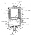
- Fig. 1 shows a section of the accumulator 1 according to an embodiment of the present invention and a partially enlarged sectional view indicating its operating condition is shown in Fig. 2.
- the accumulator 1 of this embodiment is a metallic bellows-type accumulator, which has the following structure.
- a housing 2 is provided by welding an end cover 4 (called gas end cover or lid member also) to an open end portion of a bottomed cylindrical shell 3 and an operating member 5 comprising a bellows and a bellows cap (called end member also) is accommodated inside this housing 2.
- An end portion (called fixed end portion also) of the bellows 6 is attached to the end cover 4 while the other end portion (called movable end portion) has a bellows cap 7.
- the interior of the housing 2 is divided to a pressure sealing chamber (called gas chamber) 8 inside the bellows 6 and the bellows cap 7 and an outside fluid flow-in chamber (called liquid chamber or fluid chamber also) 9 by the bellows 6 and the bellows cap 7.
- gas chamber a pressure sealing chamber
- liquid chamber or fluid chamber an outside fluid flow-in chamber
- the bellows cap 7 may be formed integrally with the bellows 6.
- the end cover 4 which forms part of the aforementioned housing 2 is provided with a pressure supply port 10 for supplying gas into the pressure sealing chamber 8.
- This pressure supply port 10 has a plug member (called gas plug also) 11 for clogging this supply port 10.
- gas plug also
- gas under a predetermined pressure is supplied into the sealing chamber 8 through the supply port 10.
- the supply port 10 is clogged with the plug member 11 so as to fill the sealing chamber 8 with gas under the predetermined pressure.
- gas to be filled preferably, nitrogen gas or inert gas is used.
- a mounting portion 12 having a thread portion 13 for connecting the accumulator 1 to a pressure pipe on a hydraulic pressure system (not shown) is provided in the center of a flat face of a wall end portion 3a which forms part of the housing 2.
- This mounting portion 12 has a fluid inlet (called fluid introduction port or fluid passage) 14 for introducing fluid on the system side into the fluid flow-in chamber 9.
- the accumulator 1 is connected to the system side through the mounting portion 12 so as to introduce fluid on the system side into the fluid flow-in chamber 9 through the fluid inlet 14.
- a ring-like sliding member (called vibration damping ring also) 15 is mounted on an outer periphery of the other end portion of the bellows 6 provided with the bellows cap 7 or the outer periphery of the bellows cap 7.
- the sliding member 15 slides along an inner peripheral face of the shell 3 at the outer periphery thereof.
- the bellows cap 7 moves in parallel to the inner peripheral face of the shell 3 while the bellows 6 is expanded or contracted in parallel to the inner peripheral face of the shell 3 under a guide by the sliding of the sliding member 15. Consequently, the bellows cap 7 or the bellows 6 is prevented from being caught by the inner peripheral face of the shell 3.
- a pressure communicating portion (not shown) is provided in this sliding member 15 in order to prevent the fluid flow-in chamber 9 from being divided to a space 9a on the outer periphery side of the bellows 6 and a space 9b below the bellows cap 7 in the same Figure by the sliding member 15.
- a concave or stepped mounting portion 3c is provided in the inner face of the wall end portion 3a of the shell 3, that is, in the peripheral portion of the opening of the supply port 10 of an end face portion 3b of the shell 3.
- An outside seal 16, an outside holder 17, an inside seal 18 and an inside holder 19 are mounted in this mounting portion 3c successively from the outer periphery.
- the outside seal 16 is provided so as to maintain the pressure of the fluid flow-in chamber 9 over a predetermined value and keep the bellows 6 from being damaged. If the pressure of fluid in the fluid flow-in chamber 9 or the pressure of fluid on the system side drops remarkably upon usage of the accumulator 1, the bellows 6 is prohibited from being expanded by a difference in pressure between the inside and the outside thereof.
- This outside seal is formed in the following structure.
- this seal 16 is formed as a lip seal moulded of a predetermined rubber-like elastic material and as shown with an enlarged diagram of Fig. 2.
- the seal 16 has an annular base portion 16a, which is to be pressed into the mounting portion 3c without being bonded thereto.
- An annular seal lip (called inner peripheral seal lip or first seal lip) is formed integrally on an end face on the side of the bellows cap of the base portion 16a such that it makes contact with the end face 7a of the bellows cap 7 freely detachably.
- An annular concave portion 16c is formed on the outer peripheral side of the seal lip 16b and an outer peripheral side seal lip (called second seal lip also) 16d is formed integrally on a further outer side of this concave portion 16c such that it is always in a firm contact with the inner face of the mounting portion 3c.
- the seal lip 16b is formed as an outward directed seal lip whose diameter is expanded outward in the diameter direction from a proximal portion to a distal portion thereof.
- this seal lip 16b makes contact with the end face 7a of the bellows cap 7, it is pressed by a pressure within the fluid flow-in chamber 9, which is a resistant pressure of sealed fluid, against the end face 7a so that it makes a firm contact therewith. Therefore, an outer peripheral face of this seal lip 16 serves as a pressure receiving face.
- Two annular rows of sealing protrusions 16e, 16f are provided coaxially at a front end portion of the seal lip 16b and these seal protrusions 16e, 16f make contact with the end face 7a of the bellows cap 7.
- the other sealing protrusion 16e or 16f keeps a firm contact with the end face 7a throughout the entire circumference so as to maintain the sealing performance. Because such double structure of the sealing protrusions 16e, 16f is provided, the sealing performance of the entire seal lip 16b is improved.
- the number of the rows formed for the sealing protrusions 16e, 16f is not restricted to two rows, but may be three or more.
- the sealing protrusions 16e, 16f make contact with the end face 7a of the bellows cap 7.
- the seal lip 16b does not bear the operation or burden as a stopper which stops the bellows cap 7 moving toward it.
- the outside holder 17 disposed on the inner peripheral side of the outside seal 16 is formed in an annular shape of rigid material such as metal or resin, and is comprised of a flat portion 17a, which is flat and annular or double-ring like, and a cylindrical rising portion 17b, which is formed integrally with this flat portion 17a such that it rises from the outer peripheral end portion of the flat portion 17a toward the bellows cap 7, its section being L-shaped or substantially L-shaped.
- the inner peripheral end portion of the flat portion 17a is engaged with an annular stepped engaging portion 19a provided in the outer peripheral face of the inside holder 19. Therefore, when the inside holder 19 is inserted into the fluid inlet 14 and fixed therein, the outside holder 17 gets fixed to the shell 3.
- the rising portion 17b is disposed just on the inner peripheral side of the outside seal 16 and a front end portion thereof is expanded in a trumpet-like or tapered form, so that the rising portion 17b holds the outside seal 16 from being removed from the mounting portion 3c.
- This rising portion 17b has also the function of backing up the seal lip 16b of the outside seal 16.
- the inside seal 18 which is disposed on the inner peripheral side of the holder 17 and held by this holder 17, is provided so as to maintain the pressure of the fluid flow-in chamber 9 over a predetermined value and keep the bellows 6 from being damaged, so that if the pressure of fluid in the fluid flow-in chamber 9 or the pressure of fluid on the system side drops remarkably upon usage of the accumulator 1, the bellows 6 is prohibited from being expanded by a difference in pressure between the inside and the outside thereof.
- This inside seal is formed in a following structure.
- this seal 18 is formed as a lip seal moulded of a predetermined rubber-like elastic material and as shown in the enlarged diagram of Fig. 2.
- the seal 18 has an annular base portion 18a, which is to be pressed into the inner peripheral side of the outside holder 17 without being bonded thereto.
- An annular seal lip (called inner peripheral seal lip or first seal lip) 18b is formed integrally on an end face on the side of the bellows cap 7 of the base portion 18a such that it makes contact with the end face 7a of the bellows cap 7 freely detachably.
- An annular concave portion 18c is formed on the outer peripheral side of the seal lip 18b and an outer peripheral side seal lip (called second seal lip also) 18d is formed integrally on a further outer side of this concave portion 18c such that it is always in a firm contact with the inner face of the outside holder 17.
- the seal lip 18b is formed as an outward directed seal lip whose diameter is expanded outward in the diameter direction from a proximal portion to a distal portion thereof.
- this seal lip 18b makes contact with the end face 7a of the bellows cap 7, it is pressed by a pressure within the fluid flow-in chamber 9, which is a resistant pressure of sealed fluid, against the end face 7a so that it makes a firm contact therewith. Therefore, an outer peripheral face of this seal lip 18b serves as a pressure receiving face.
- Two annular rows of sealing protrusions 18e, 18f are provided coaxially at a front end portion of the seal lip 18b and these seal protrusions 18e, 18f make contact with the end face 7a of the bellows cap 7.
- the other sealing protrusion 18e or 18f keeps a firm contact with the end face 7a throughout the entire circumference so as to maintain the sealing performance. Because such double structure of the sealing protrusions 18e, 18f is provided, the sealing performance of the entire seal lip 18b is improved.
- the number of the rows formed for the sealing protrusions 18e, 18f is not restricted to two rows, but may be three or more.
- the sealing protrusions 18e, 18f make contact with the end face 7a of the bellows cap 7.
- the seal lip 18b does not bear the operation or burden as a stopper which stops the bellows cap 7 moving toward it.
- the inside holder 19 disposed on the inner peripheral side of the outside holder 17 and the inside seal 18 is formed in a cylindrical or pipe-like form of such rigid material as metal or resin, and is comprised of an insertion portion 19b having a relatively small diameter and to be inserted into the fluid inlet 14 and a rising portion 19c formed integrally with this insertion portion 19b and having a relatively large diameter.
- the aforementioned, annular stepped engaging portion 19a is provided on the border between this insertion portion 19b and the rising portion 19c.
- the insertion portion 19b is fixed to the shell 3 after it is pressed into the fluid inlet 14, it is permissible to expand the front end portion (bottom portion in the same Figure) of the insertion portion 19b in a trumpet-like or tapered form after the insertion portion 18b is inserted into the fluid inlet 14 so that it is fixed to the shell 3.
- part of the inner face of the fluid inlet 14 is provided with a trumpet-like or tapered engaging portion 14a preliminarily.
- the accumulator 1 of this embodiment contains an abnormal sound preventing mechanism having the following structure.
- the bellows cap 7 mounted on the movable end portion of the bellows 6, which is the operating member 5, is provided with a through hole-like throttling mechanism 20 damping a sound generated by pulsating waves and having a relatively small diameter.
- a cup-like chamber forming member 21 is mounted on the side of the sealing chamber 8 of the bellows cap 7 and on the inner side of the bellows 6 by engaging, bonding or welding.
- This chamber forming member 21 forms a chamber room 22 having a predetermined capacity for damping a sound generated by the pulsating waves.
- the through hole-like throttling mechanism 20 is provided in the center of the flat face of the bellows cap 7 such that it opposes the fluid inlet 14.
- the chamber room 22 communicates with the fluid flow-in chamber 9 through the throttling mechanism 20.
- the bellows cap has a stepped engaging portion 7b for positioning the chamber forming member 21 in the center of the flat face.
- the accumulator 1 having the aforementioned structure accumulates and discharges the pressure of oil in the system as a pressure accumulating apparatus and the following operation and effect are exerted with the aforementioned structure.
- the pulsating wave is generated when the pressure of oil is accumulated or discharged, thereby generating a sound (abnormal sound).
- fluid with the pulsating wave flows into the fluid flow-in chamber 9 through the fluid inlet 14 in the accumulator 1 having the above-described structure, pulsating wave energy is converted to loss energy due to contracted flow and throttling by the through hole-like throttling mechanism 20 and used as loss of dynamic pressure by the chamber room 22.
- the pulsating wave can be damped and consequently, a sound generated by the pulsating wave can be damped.
- the abnormal sound preventing mechanism comprised of the throttling mechanism 20 and the chamber room 22 acts in a range from zero in system pressure to a gas sealing pressure.
- the present invention exerts the following effects.
- the pulsating energy is converted to loss energy due to contracted flow and throttling by the throttling mechanism provided on the movable end portion of the operating member including the bellows and used as loss of dynamic pressure by the chamber room. Consequently, the pulsating can be damped so that a sound due to the pulsating wave can be damped. Therefore, an accumulator having an excellent silencing performance can be provided.
- the pulsating energy is converted to loss energy due to contracted flow and throttling by the throttling mechanism provided on the bellows cap mounted on the end portion of the bellows and used as loss of dynamic pressure by the chamber room. Consequently, the pulsating can be damped so that a sound due to the pulsating wave can be damped. Therefore, an accumulator having an excellent silencing performance can be provided.
- the throttling mechanism is provided at a position opposing the fluid inlet, the throttling mechanism is likely to be actuated to fluid flowing through the fluid inlet. Even if the movable end of the operating member or the bellows cap approaches the fluid inlet, the operation for damping the pulsation can be exerted.
Landscapes
- Engineering & Computer Science (AREA)
- Physics & Mathematics (AREA)
- Fluid Mechanics (AREA)
- Mechanical Engineering (AREA)
- General Engineering & Computer Science (AREA)
- Supply Devices, Intensifiers, Converters, And Telemotors (AREA)
Abstract
Description
- 1:
- accumulator
- 2:
- housing
- 3:
- shell
- 4:
- end cover
- 5:
- operating member
- 6:
- bellows
- 7:
- bellows cap
- 8:
- pressure sealing chamber
- 9:
- fluid flow-in chamber
- 10:
- pressure supplying port
- 11:
- plug member
- 12:
- mounting portion
- 13:
- thread portion
- 14:
- flow inlet
- 15:
- sliding member
- 16,
- 18: seal
- 17,
- 19: holder
- 20:
- throttling mechanism
- 21:
- chamber forming member
- 22:
- chamber room
Claims (3)
- An accumulator wherein an operating member (5) containing a bellows (6) is disposed inside a housing (2) so as to divide the interior of the housing (2) to a pressure sealing chamber (8) and a fluid flow-in chamber (9) and the housing is provided with a fluid inlet (14) for introducing fluid to the fluid flow-in chamber (9) from the side of a fluid pipe,
the accumulator further comprising a throttling mechanism (20) and a chamber room (22) for damping a sound generated by the pulsating wave, provided at a movable end portion of the operating member (5). - The accumulator as claimed in claim 1 wherein the operating member (5) has a bellows cap (7) to be attached to the movable end portion of the bellows (6), and the 'bellows cap (7) contains the throttling mechanism (20) and the chamber room (22).
- The accumulator as claimed in claim 1 or 2 wherein the throttling mechanism (20) is provided at a position opposing the fluid inlet (14).
Applications Claiming Priority (3)
| Application Number | Priority Date | Filing Date | Title |
|---|---|---|---|
| JP2000198102A JP2002013501A (en) | 2000-06-30 | 2000-06-30 | Accumulator |
| JP2000198102 | 2000-06-30 | ||
| PCT/IB2001/001170 WO2002001077A1 (en) | 2000-06-30 | 2001-07-02 | Accumulator |
Publications (3)
| Publication Number | Publication Date |
|---|---|
| EP1296063A1 true EP1296063A1 (en) | 2003-03-26 |
| EP1296063A4 EP1296063A4 (en) | 2005-07-06 |
| EP1296063B1 EP1296063B1 (en) | 2006-03-29 |
Family
ID=18696312
Family Applications (1)
| Application Number | Title | Priority Date | Filing Date |
|---|---|---|---|
| EP01949808A Expired - Lifetime EP1296063B1 (en) | 2000-06-30 | 2001-07-02 | Accumulator |
Country Status (6)
| Country | Link |
|---|---|
| US (1) | US6892765B2 (en) |
| EP (1) | EP1296063B1 (en) |
| JP (1) | JP2002013501A (en) |
| AU (1) | AU2001270922A1 (en) |
| DE (1) | DE60118389T2 (en) |
| WO (1) | WO2002001077A1 (en) |
Families Citing this family (21)
| Publication number | Priority date | Publication date | Assignee | Title |
|---|---|---|---|---|
| JP2002070801A (en) * | 2000-08-30 | 2002-03-08 | Aisin Seiki Co Ltd | accumulator |
| DE10307129A1 (en) * | 2003-02-20 | 2004-09-16 | Robert Bosch Gmbh | End position seal for a fluid store for a motor vehicle brake unit has elastic partition between two spaces and a seal and ring piece |
| JPWO2004102009A1 (en) * | 2003-05-16 | 2006-07-13 | Nok株式会社 | accumulator |
| JP4507519B2 (en) * | 2003-07-03 | 2010-07-21 | 株式会社アドヴィックス | Brake fluid pressure control unit |
| US20050011821A1 (en) * | 2003-07-17 | 2005-01-20 | Sigma-Aldrich Co. | High throughput flash purification stand and cartridge |
| DE102004004341A1 (en) * | 2004-01-29 | 2005-08-18 | Hydac Technology Gmbh | Pressure accumulator, in particular pulsation damper |
| WO2005087339A1 (en) * | 2004-03-04 | 2005-09-22 | Sigma-Aldrich Co. | A high throughput flash purification stand and cartridge |
| JP4272604B2 (en) * | 2004-08-23 | 2009-06-03 | 日本発條株式会社 | Pressure vessel and pressure accumulator / buffer |
| JP4735811B2 (en) * | 2005-04-15 | 2011-07-27 | Nok株式会社 | accumulator |
| US20080092969A1 (en) * | 2006-08-07 | 2008-04-24 | Diperna Paul Mario | Variable flow reshapable flow restrictor apparatus and related methods |
| US7855024B2 (en) * | 2006-12-27 | 2010-12-21 | Proton Energy Systems, Inc. | Compartmentalized storage tank for electrochemical cell system |
| JP5102576B2 (en) * | 2007-10-10 | 2012-12-19 | Nok株式会社 | accumulator |
| RU2493892C2 (en) * | 2007-10-30 | 2013-09-27 | Эрбюс Операсьон | High-integrity fluid discharge device |
| EP2340371A1 (en) * | 2008-10-03 | 2011-07-06 | Eaton Corporation | Hydraulic accumulator and method of manufacture |
| JP5474333B2 (en) * | 2008-11-05 | 2014-04-16 | イーグル工業株式会社 | accumulator |
| US7810522B1 (en) * | 2010-04-26 | 2010-10-12 | Nok Corporation | Accumulator |
| DE102012012971B4 (en) * | 2012-06-29 | 2024-08-08 | Zf Active Safety Gmbh | Damping element for a motor vehicle hydraulic system |
| WO2015015882A1 (en) * | 2013-07-29 | 2015-02-05 | イーグル工業株式会社 | Accumulator |
| JP6504827B2 (en) | 2015-01-16 | 2019-04-24 | 東京エレクトロン株式会社 | Etching method |
| US12522039B2 (en) * | 2023-03-22 | 2026-01-13 | Advanced Suspension Technology Llc | Suspension system with proportional pressure accumulator |
| US12188492B1 (en) * | 2023-11-21 | 2025-01-07 | DRiV Automotive Inc. | Method of charging a bellows accumulator |
Family Cites Families (16)
| Publication number | Priority date | Publication date | Assignee | Title |
|---|---|---|---|---|
| US3714964A (en) * | 1968-10-24 | 1973-02-06 | Factory Mutual Res Corp | Double rate flow controller |
| US4527580A (en) * | 1983-11-25 | 1985-07-09 | Sundstrand Corporation | Volume control device |
| JP2756792B2 (en) | 1988-08-30 | 1998-05-25 | 東洋農機株式会社 | Auxiliary equipment for mortar board |
| JPH0547281Y2 (en) * | 1988-11-09 | 1993-12-13 | ||
| JPH02266101A (en) * | 1989-04-05 | 1990-10-30 | Nhk Spring Co Ltd | Accumulator |
| JP2649091B2 (en) * | 1989-09-05 | 1997-09-03 | 株式会社 豊田中央研究所 | High pressure liquid supply device |
| DE4318553C2 (en) * | 1993-06-04 | 1995-05-18 | Daimler Benz Ag | Adaptive hydropneumatic pulsation damper |
| JPH09242702A (en) * | 1996-03-05 | 1997-09-16 | Nok Corp | Accumulator |
| JPH116572A (en) * | 1997-06-18 | 1999-01-12 | Nok Corp | Accumulator |
| EP0980981B1 (en) * | 1998-08-17 | 2003-11-26 | Continental Teves AG & Co. oHG | Fluid pressure accumulator |
| JP3812621B2 (en) * | 1998-10-15 | 2006-08-23 | Nok株式会社 | End face seal |
| EP1052412B1 (en) * | 1999-05-12 | 2005-03-09 | NHK Spring Co., Ltd. | Accumulator and manufacturing process thereof |
| US6644354B2 (en) * | 2000-04-04 | 2003-11-11 | Continental Teves Ag & Co., Ohg | Hydraulic fluid accumulator |
| JP3513096B2 (en) * | 2000-09-25 | 2004-03-31 | トヨタ自動車株式会社 | Accumulator and abnormality detection device for accumulator |
| JP2003172301A (en) * | 2001-12-04 | 2003-06-20 | Nhk Spring Co Ltd | accumulator |
| JP3844064B2 (en) * | 2002-03-25 | 2006-11-08 | 株式会社アドヴィックス | Bellows hydraulic accumulator |
-
2000
- 2000-06-30 JP JP2000198102A patent/JP2002013501A/en not_active Withdrawn
-
2001
- 2001-07-02 US US10/312,642 patent/US6892765B2/en not_active Expired - Fee Related
- 2001-07-02 DE DE60118389T patent/DE60118389T2/en not_active Expired - Fee Related
- 2001-07-02 AU AU2001270922A patent/AU2001270922A1/en not_active Abandoned
- 2001-07-02 EP EP01949808A patent/EP1296063B1/en not_active Expired - Lifetime
- 2001-07-02 WO PCT/IB2001/001170 patent/WO2002001077A1/en not_active Ceased
Also Published As
| Publication number | Publication date |
|---|---|
| US20040003854A1 (en) | 2004-01-08 |
| US6892765B2 (en) | 2005-05-17 |
| AU2001270922A1 (en) | 2002-01-08 |
| DE60118389D1 (en) | 2006-05-18 |
| WO2002001077A1 (en) | 2002-01-03 |
| EP1296063B1 (en) | 2006-03-29 |
| EP1296063A4 (en) | 2005-07-06 |
| JP2002013501A (en) | 2002-01-18 |
| DE60118389T2 (en) | 2006-08-17 |
Similar Documents
| Publication | Publication Date | Title |
|---|---|---|
| EP1296063B1 (en) | Accumulator | |
| US20060130920A1 (en) | Hydraulic accumulator | |
| JPH02266101A (en) | Accumulator | |
| DK0663348T3 (en) | Device for emptying a pipe bag | |
| JPH0480255B2 (en) | ||
| SE468721B (en) | VALVE DEVICE FOR GENERATING SHORT-TERM PRESSURE PULSES EXAMPLE FOR BLEASING BASIC FILTER ELEMENTS | |
| KR920009648A (en) | Ignition Unit for Air Bag Gas Generator | |
| JP2003262201A (en) | Accumulator | |
| US4305428A (en) | Surge absorber | |
| CN104024653A (en) | Accumulator | |
| US6651698B1 (en) | Suppressor for manifold fluid line | |
| JP4257027B2 (en) | Liquid tank | |
| JPH0686072U (en) | Pulsation damper for liquid chromatography equipment | |
| US4112978A (en) | Valve for an opening of a pressure vessel | |
| US4351363A (en) | Hydro-pneumatic pressure vessel | |
| JP4288770B2 (en) | Scroll fluid machinery | |
| GB2203799A (en) | Accumulator provided with an insert | |
| JP3794316B2 (en) | accumulator | |
| US4201246A (en) | Pressure accumulator | |
| JPH0483903A (en) | Accumulator | |
| JPH0658302A (en) | Filter with accumulator function | |
| KR20010071144A (en) | Seal Structure for Rodless Cylinder | |
| JP3212384B2 (en) | accumulator | |
| JP2001020901A (en) | Accumulator | |
| JP5178552B2 (en) | Pressure vessel, accumulator and pressure vessel lid manufacturing method |
Legal Events
| Date | Code | Title | Description |
|---|---|---|---|
| PUAI | Public reference made under article 153(3) epc to a published international application that has entered the european phase |
Free format text: ORIGINAL CODE: 0009012 |
|
| 17P | Request for examination filed |
Effective date: 20021230 |
|
| AK | Designated contracting states |
Kind code of ref document: A1 Designated state(s): AT BE CH CY DE DK ES FI FR GB GR IE IT LI LU MC NL PT SE TR Designated state(s): AT BE CH CY DE DK ES FI FR GB GR IE IT LI LU MC NL PT SE TR |
|
| AX | Request for extension of the european patent |
Extension state: AL LT LV MK RO SI |
|
| RBV | Designated contracting states (corrected) |
Designated state(s): AT BE CH DE FR GB LI |
|
| A4 | Supplementary search report drawn up and despatched |
Effective date: 20050524 |
|
| RIC1 | Information provided on ipc code assigned before grant |
Ipc: 7F 16L 55/04 B Ipc: 7F 16L 55/033 B Ipc: 7F 15B 1/10 B Ipc: 7F 15B 1/00 A |
|
| GRAP | Despatch of communication of intention to grant a patent |
Free format text: ORIGINAL CODE: EPIDOSNIGR1 |
|
| GRAS | Grant fee paid |
Free format text: ORIGINAL CODE: EPIDOSNIGR3 |
|
| GRAA | (expected) grant |
Free format text: ORIGINAL CODE: 0009210 |
|
| AK | Designated contracting states |
Kind code of ref document: B1 Designated state(s): DE FR GB |
|
| RBV | Designated contracting states (corrected) |
Designated state(s): DE FR GB |
|
| REG | Reference to a national code |
Ref country code: GB Ref legal event code: FG4D |
|
| REF | Corresponds to: |
Ref document number: 60118389 Country of ref document: DE Date of ref document: 20060518 Kind code of ref document: P |
|
| PGFP | Annual fee paid to national office [announced via postgrant information from national office to epo] |
Ref country code: GB Payment date: 20060628 Year of fee payment: 6 |
|
| PGFP | Annual fee paid to national office [announced via postgrant information from national office to epo] |
Ref country code: DE Payment date: 20060629 Year of fee payment: 6 |
|
| PGFP | Annual fee paid to national office [announced via postgrant information from national office to epo] |
Ref country code: FR Payment date: 20060719 Year of fee payment: 6 |
|
| PLBE | No opposition filed within time limit |
Free format text: ORIGINAL CODE: 0009261 |
|
| STAA | Information on the status of an ep patent application or granted ep patent |
Free format text: STATUS: NO OPPOSITION FILED WITHIN TIME LIMIT |
|
| 26N | No opposition filed |
Effective date: 20070102 |
|
| EN | Fr: translation not filed | ||
| GBPC | Gb: european patent ceased through non-payment of renewal fee |
Effective date: 20070702 |
|
| PG25 | Lapsed in a contracting state [announced via postgrant information from national office to epo] |
Ref country code: FR Free format text: LAPSE BECAUSE OF FAILURE TO SUBMIT A TRANSLATION OF THE DESCRIPTION OR TO PAY THE FEE WITHIN THE PRESCRIBED TIME-LIMIT Effective date: 20070309 Ref country code: DE Free format text: LAPSE BECAUSE OF NON-PAYMENT OF DUE FEES Effective date: 20080201 |
|
| PG25 | Lapsed in a contracting state [announced via postgrant information from national office to epo] |
Ref country code: GB Free format text: LAPSE BECAUSE OF NON-PAYMENT OF DUE FEES Effective date: 20070702 |