EP1295968A1 - Gas diffusion electrode, method for manufacturing the same and fuel cell using it - Google Patents
Gas diffusion electrode, method for manufacturing the same and fuel cell using it Download PDFInfo
- Publication number
- EP1295968A1 EP1295968A1 EP01934519A EP01934519A EP1295968A1 EP 1295968 A1 EP1295968 A1 EP 1295968A1 EP 01934519 A EP01934519 A EP 01934519A EP 01934519 A EP01934519 A EP 01934519A EP 1295968 A1 EP1295968 A1 EP 1295968A1
- Authority
- EP
- European Patent Office
- Prior art keywords
- gas diffusion
- diffusion electrode
- fluororesin
- micro particles
- polymer electrolyte
- Prior art date
- Legal status (The legal status is an assumption and is not a legal conclusion. Google has not performed a legal analysis and makes no representation as to the accuracy of the status listed.)
- Granted
Links
Images


Classifications
-
- H—ELECTRICITY
- H01—ELECTRIC ELEMENTS
- H01M—PROCESSES OR MEANS, e.g. BATTERIES, FOR THE DIRECT CONVERSION OF CHEMICAL ENERGY INTO ELECTRICAL ENERGY
- H01M4/00—Electrodes
- H01M4/86—Inert electrodes with catalytic activity, e.g. for fuel cells
- H01M4/88—Processes of manufacture
- H01M4/8825—Methods for deposition of the catalytic active composition
- H01M4/8853—Electrodeposition
-
- C—CHEMISTRY; METALLURGY
- C25—ELECTROLYTIC OR ELECTROPHORETIC PROCESSES; APPARATUS THEREFOR
- C25D—PROCESSES FOR THE ELECTROLYTIC OR ELECTROPHORETIC PRODUCTION OF COATINGS; ELECTROFORMING; APPARATUS THEREFOR
- C25D15/00—Electrolytic or electrophoretic production of coatings containing embedded materials, e.g. particles, whiskers, wires
-
- H—ELECTRICITY
- H01—ELECTRIC ELEMENTS
- H01M—PROCESSES OR MEANS, e.g. BATTERIES, FOR THE DIRECT CONVERSION OF CHEMICAL ENERGY INTO ELECTRICAL ENERGY
- H01M4/00—Electrodes
- H01M4/02—Electrodes composed of, or comprising, active material
- H01M4/04—Processes of manufacture in general
- H01M4/0438—Processes of manufacture in general by electrochemical processing
- H01M4/045—Electrochemical coating; Electrochemical impregnation
- H01M4/0457—Electrochemical coating; Electrochemical impregnation from dispersions or suspensions; Electrophoresis
-
- H—ELECTRICITY
- H01—ELECTRIC ELEMENTS
- H01M—PROCESSES OR MEANS, e.g. BATTERIES, FOR THE DIRECT CONVERSION OF CHEMICAL ENERGY INTO ELECTRICAL ENERGY
- H01M4/00—Electrodes
- H01M4/86—Inert electrodes with catalytic activity, e.g. for fuel cells
- H01M4/8605—Porous electrodes
-
- H—ELECTRICITY
- H01—ELECTRIC ELEMENTS
- H01M—PROCESSES OR MEANS, e.g. BATTERIES, FOR THE DIRECT CONVERSION OF CHEMICAL ENERGY INTO ELECTRICAL ENERGY
- H01M4/00—Electrodes
- H01M4/86—Inert electrodes with catalytic activity, e.g. for fuel cells
- H01M4/88—Processes of manufacture
- H01M4/8803—Supports for the deposition of the catalytic active composition
- H01M4/8807—Gas diffusion layers
-
- H—ELECTRICITY
- H01—ELECTRIC ELEMENTS
- H01M—PROCESSES OR MEANS, e.g. BATTERIES, FOR THE DIRECT CONVERSION OF CHEMICAL ENERGY INTO ELECTRICAL ENERGY
- H01M8/00—Fuel cells; Manufacture thereof
- H01M8/10—Fuel cells with solid electrolytes
- H01M8/1004—Fuel cells with solid electrolytes characterised by membrane-electrode assemblies [MEA]
-
- Y—GENERAL TAGGING OF NEW TECHNOLOGICAL DEVELOPMENTS; GENERAL TAGGING OF CROSS-SECTIONAL TECHNOLOGIES SPANNING OVER SEVERAL SECTIONS OF THE IPC; TECHNICAL SUBJECTS COVERED BY FORMER USPC CROSS-REFERENCE ART COLLECTIONS [XRACs] AND DIGESTS
- Y02—TECHNOLOGIES OR APPLICATIONS FOR MITIGATION OR ADAPTATION AGAINST CLIMATE CHANGE
- Y02E—REDUCTION OF GREENHOUSE GAS [GHG] EMISSIONS, RELATED TO ENERGY GENERATION, TRANSMISSION OR DISTRIBUTION
- Y02E60/00—Enabling technologies; Technologies with a potential or indirect contribution to GHG emissions mitigation
- Y02E60/10—Energy storage using batteries
-
- Y—GENERAL TAGGING OF NEW TECHNOLOGICAL DEVELOPMENTS; GENERAL TAGGING OF CROSS-SECTIONAL TECHNOLOGIES SPANNING OVER SEVERAL SECTIONS OF THE IPC; TECHNICAL SUBJECTS COVERED BY FORMER USPC CROSS-REFERENCE ART COLLECTIONS [XRACs] AND DIGESTS
- Y02—TECHNOLOGIES OR APPLICATIONS FOR MITIGATION OR ADAPTATION AGAINST CLIMATE CHANGE
- Y02E—REDUCTION OF GREENHOUSE GAS [GHG] EMISSIONS, RELATED TO ENERGY GENERATION, TRANSMISSION OR DISTRIBUTION
- Y02E60/00—Enabling technologies; Technologies with a potential or indirect contribution to GHG emissions mitigation
- Y02E60/30—Hydrogen technology
- Y02E60/50—Fuel cells
-
- Y—GENERAL TAGGING OF NEW TECHNOLOGICAL DEVELOPMENTS; GENERAL TAGGING OF CROSS-SECTIONAL TECHNOLOGIES SPANNING OVER SEVERAL SECTIONS OF THE IPC; TECHNICAL SUBJECTS COVERED BY FORMER USPC CROSS-REFERENCE ART COLLECTIONS [XRACs] AND DIGESTS
- Y02—TECHNOLOGIES OR APPLICATIONS FOR MITIGATION OR ADAPTATION AGAINST CLIMATE CHANGE
- Y02P—CLIMATE CHANGE MITIGATION TECHNOLOGIES IN THE PRODUCTION OR PROCESSING OF GOODS
- Y02P70/00—Climate change mitigation technologies in the production process for final industrial or consumer products
- Y02P70/50—Manufacturing or production processes characterised by the final manufactured product
Definitions
- the present invention relates to a gas diffusion electrode suitable for use as an oxygen cathode in a chlor-alkari electrolysis, as well as in a fuel cell.
- the present invention relates to a gas diffusion electrode capable of being manufactured in a short time through a simple operation, a method for manufacturing the gas diffusion electrode, and a fuel cell employing, as a compositional material, the gas diffusion electrode, in particular, a polymer electrolyte fuel cell.
- a gas diffusion electrode is used, for example, as an oxygen cathode in a chlor-alkari electrolysis and in an oxygen-hydrogen fuel cell.
- a fuel cell employing the gas diffusion electrode comprises three components, i.e., an oxygen electrode (cathode) for supplying oxygen, an electrolytic plate for holding an electrolyte, and a fuel electrode (anode) to which fuel is supplied.
- an oxygen electrode (cathode) for supplying oxygen is used as the oxygen cathode.
- a polymer electrolyte fuel cell has a structure that gas diffusion electrodes are arranged on both surfaces of an ion exchange membrane (polymer electrolyte film).
- Such a gas diffusion electrode comprises a reaction layer and a gas supply layer.
- a liquid electrolyte and reaction gas are supplied to the electrode having a fixed surface, whereby a three-phase interface is formed on the electrode surface. Then, the electrochemical reaction progresses at the interface for performing power generation or electrode restoration.
- the gas diffusion electrode is usually made up of a catalyst, carbon black, polytetrafluoroethylene (PTFE), and a current collector.
- PTFE polytetrafluoroethylene
- the gas diffusion electrode has a thickness of about 0.6 mm and is divided into a gas supply layer of about 0.5 mm and a reaction layer of about 0.1 mm.
- the gas supply layer constituting the gas diffusion electrode is made up of, e.g., micro particles of hydrophobic carbon black and polytetrafluoroethylene (PTFE).
- PTFE polytetrafluoroethylene
- reaction layer is made up of micro particles of a catalyst, hydrophilic carbon black, hydrophobic carbon black, and polytetrafluoroethylene (PTFE).
- PTFE polytetrafluoroethylene
- a liquid dispersion containing micro particles of a catalyst, hydrophilic carbon black, hydrophobic carbon black, PTFE, etc., as electrode materials, is used.
- an additional solution of a polymer electrolyte (such as a fluorine-based ion exchange resin, for example, liquid Nafion made by DuPont) is used.
- aqueous dispersion in which those materials are evenly mixed and dispersed is prepared using a quantity of water with about 20 to 100 times the weight of the carbon black inclusive of a surfactant.
- Ultrasonic waves for example, are irradiated to finely disperse the gas diffusion electrode materials in an aqueous medium. With irradiation of ultrasonic waves, material particles are stabilized in the colloidal state.
- the gas diffusion electrode is fabricated using the aqueous medium in which the gas diffusion electrode materials are dispersed (hereinafter referred to simply as the "aqueous dispersion").
- the aqueous dispersion medium must be removed from the aqueous dispersion.
- dispersion medium is removed by filtering, for example, a difficulty would arise in filtering micro particles finely dispersed in the stabilized state and a long time, two days or more, would be required until the filtering is completed.
- the filtering time could be shortened to about 3 hours, but another problem would be more likely to occur in that PTFE micro particles tend to segregate and the PTFE concentration in the formed reaction layer is locally different, thus resulting in unevenness of the composition.
- the separated dispersoid After removing the dispersion medium by, e.g., filtering, the separated dispersoid is dried and formed into sheets with the addition of solvent naphtha. A sheet for the gas supply layer and a sheet for the reaction layer are thus obtained.
- the sheets are laid one on another to form a gas diffusion electrode sheet having a predetermined thickness.
- the sheet is further dried.
- the gas diffusion electrode is obtained by hot pressing the dried sheet together with a current collector.
- a polymer electrolyte fuel cell having a structure in which gas diffusion electrodes are arranged on both surfaces of an ion exchange membrane is manufactured as follows.
- a solution of a polymer electrolyte such as a fluorine-based ion exchange resin, for example, liquid Nafion made by DuPont
- a flocculant is added to obtain a mixed liquid dispersion of the fluororesin and the catalyst-carrying carbon black caught by the fluororesin.
- the mixed liquid dispersion is coated on, e.g., a Teflon film for forming the reaction layer and then dried to form a reaction layer film.
- This reaction layer film is press-bonded to a film of a polymer electrolyte (such as a fluorine-based ion exchange resin, for example, Nafion made by DuPont) while heating to obtain a joined electrode of the reaction layer and the polymer electrolyte.
- a polymer electrolyte such as a fluorine-based ion exchange resin, for example, Nafion made by DuPont
- Solidifying the aqueous dispersion while maintaining the evenly dispersed state requires the aqueous dispersion to be subjected to filtering. As stated above, however, the filtering encounters difficulty and takes a long time, two days or more, until the filtering is completed.
- the inventor has analyzed the steps employed in conventional techniques for obtaining a gas diffusion electrode having a reaction layer and a gas supply layer, which have a low water content and are uniform, in a short time while maintaining dispersed state in the electorode.
- the inventor has made intensive studies on means for manufacturing, with simpler means, not only a gas diffusion electrode, but also a reaction layer and a gas supply layer of the gas diffusion electrode, which are basic elements of a polymer electrolyte fuel cell.
- An object of the present invention is to provide a high-performance and long-life gas diffusion electrode at lower cost by a simple manufacturing method for deposit, from a aqueous dispersion having a high water content, a fluororesin-containing in porous state, which has a small water content, causes no concentration difference due to segregation of fluororesin, and has an even concentration distribution, in a short time, and for forming a reaction layer and a gas supply layer of the gas diffusion electrode by using the prepared fluororesin-containing porous deposit.
- Another object of the present invention is to provide a polymer electrolyte fuel cell that has superior mass-productivity, can be manufactured by a simpler apparatus at a lower cost, and has high performance and a long life, wherein a polymer electrolyte film as an electrode material is also formed by a method comprising the steps of immersing a cathode and an anode in a solution of a polymer electrolyte, e.g., Nafion (made by DuPont), (hereinafter referred to simply as "solution") as an electrophoresis liquid, applying an electrical current between both the electrodes to move the polymer electrolyte toward the anode by electrophoresis, and electrodepositing the polymer electrolyte on the anode or a perforated plate disposed near the anode.
- a polymer electrolyte e.g., Nafion (made by DuPont)
- the present invention provides a gas diffusion electrode including a gas supply layer or/and a reaction layer as a compositional material, which are each formed on a surface of a conductive base through deposit by electrophoresis of gas diffusion electrode materials comprising micro particles of fluororesin, as a primary constituent, dispersed in dispersion medium .
- the present invention provides a gas diffusion electrode including a gas supply layer or/and a reaction layer, as a compositional material, which are each formed on a surface of a conductive base through deposit by electrophoresis of gas diffusion electrode materials comprising micro particles of fluororesin as a primary constituent and one or more kinds of micro particles selected from among hydrophobic carbon black, hydrophilic carbon black and catalysts dispersed in dispersion medium.
- the present invention provides a method for manufacturing a gas diffusion electrode comprising the steps of forming a fluororesin-containing porous deposit through deposition, on a surface of a conductive base, by electrophoresis of gas diffusion electrode materials comprising micro particles of fluororesin, as a primary constituent, dispersed in a dispersion medium, and employing the formed fluororesin-containing porous deposit as a gas supply layer or/and a reaction layer of the gas diffusion electrode.
- the present invention provides a method for manufacturing a gas diffusion electrode comprising the steps of forming a fluororesin-containing porous deposit on a surface of a conductive base, by electrophoresis of gas diffusion electrode materials comprising micro particles of fluororesin as a primary constituent and one or more kinds of micro particles selected from among hydrophobic carbon black, hydrophilic carbon black and catalysts dispersed in dispersion medium, and employing the formed fluororesin-containing porous deposit as a gas supply layer or/and a reaction layer of the gas diffusion electrode.
- the present invention provides a fuel cell including, as a compositional material, the gas diffusion electrode set forth above.
- the present invention provides a polymer electrolyte fuel cell including, as a compositional material, the gas diffusion electrode set forth above.
- a gas diffusion electrode of the present invention particularly a reaction layer and a gas supply layer of the gas diffusion electrode, a method for manufacturing them, and a fuel cell employing them will be described in detail with reference to the accompanying drawings. Note that the present invention is not limited to the embodiments and examples described below.
- reaction layer and the gas supply layer constituting the gas diffusion electrode is characterized by being formed by electrophoretic deposit.
- a polymer electrolyte film for use in a polymer electrolyte fuel cell having a structure, in which the gas diffusion electrodes are arranged on both surfaces of the polymer electrolyte film can also be formed by electrophoretic deposit.
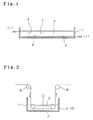
- Fig. 1 is a schematic explanatory view showing a method for manufacturing a gas diffusion electrode according to the present invention.
- the manufacturing method is carried out using, as basic component elements, a DC stabilized power supply, a pair of porous opposing electrodes disposed parallel to each other, a silver mesh as a perforated plate, and a liquid dispersion of gas diffusion electrode materials primarily comprising micro particles of fluororesin.
- a silver mesh is laid at the bottom of a cylindrical glass container 1 to serve as an anode 2, and a liquid dispersion 4 is filled in the glass container 1.
- a nickel mesh is disposed at a position slightly lower than the surface level of the liquid dispersion 4 parallel to the silver mesh in order to serve as a cathode 3.
- electrophoresis can be performed regardless of whether the anode 2 and the cathode 3 are arranged to extend horizontally or vertically.
- the anode 2 and the cathode 3 be arranged to extend horizontally and a conductive base on which the gas diffusion electrode materials are deposited, i.e., the anode 2, be arranged below the cathode 3 so that the direction in which the fluororesin micro particles, etc. are moved under electrophoresis is the same as the settling-down direction of those micro particles by the action of gravity.
- Such an arrangement of the anode 2 and the cathode 3 is advantageous in that the time required for movement of the gas diffusion electrode materials can be shortened for an improvement in the efficiency, and the gas diffusion electrode materials can be evenly deposited on the anode 2, i.e., the conductive base, in the same composition.
- the anode 2 In electrophoresis, the anode 2 is not always required to be held stationary. By continuously moving the anode 2 as shown in Fig. 2, it is possible to manufacture a porous deposit, on which the gas diffusion electrode materials are evenly deposited, in a continuous manner.
- the porous deposit is manufactured in a continuous manner by employing a metal mesh as the anode, which serves also as a base for the porous deposit, and by continuously moving the metal mesh.
- Materials usable for the anode 2 include, e.g., metals such as noble metals, silver, copper, zinc, iron, aluminum, nickel and stainless, alloys of two or more selected from among them, and carbon.
- the cathode 3 can also be made of similar materials.
- the distance between both the electrodes is preferably in the range of 5 to 100 mm. If the distance is too short, there is a risk of short circuit, and if it is too long, a higher voltage power supply is required.
- a deposit formed by electrodeposition contains the metal of about 0.01 to 2% and even such a trace amount of the metal may function as a catalyst in the gas diffusion electrode. If the presence of that metal raises a problem, the anode 2 is preferably made of carbon, platinum, gold, palladium or the like.
- the carbon plate surface is preferably plated with a metal, e.g., zinc.
- the metal used as the anode 2 is preferably in the form of a mesh, but it may be in the form of a plate. In the case of a mesh, the mesh size is preferably in the range of about 0.5 to 2 mm.
- the cathode 3 may be in the form of a mesh or a plate, but a mesh is preferable because generated hydrogen bubbles are more easily removed.
- the gas diffusion electrode is also usable.
- a fibrous material may be closely disposed to the surface of the anode 2 so that the fibrous material is embedded in the porous deposit formed by electrophoresis.
- the gas diffusion electrode materials can be deposited on the filter, and the porous deposit formed by electrophoresis can be easily separated from the anode 2.
- the diaphragm can be formed of, e.g., a porous membrane or an ion exchange membrane.
- the ion exchange membrane may be a cation exchange membrane, a composite membrane of cation exchange membrane and a carboxylic acid membrane, etc.
- the liquid dispersion of the gas diffusion electrode materials primarily comprising micro particles of fluororesin is prepared as follows.
- hydrophobic carbon black is dispersed in water containing a surfactant under agitation, and then further dispersed using a jet mill for reducing the particle size to 1 micron or less.
- a dispersion of fluororesin micro particles e.g., a PTFE dispersion, followed by mixing under agitation.
- an alcohol solution of a polymer electrolyte such as a solution of a fluorine-based ion exchange resin, for example, Nafion made by DuPont
- a polymer electrolyte such as a solution of a fluorine-based ion exchange resin, for example, Nafion made by DuPont
- This mixing contributes to increased adhesion between the reaction layer and the polymer electrolyte film.
- the fluororesin micro particles may be, for example, micro particles of a polytetrafluoroethylene, a copolymer of tetrafluoroethylene and hexafluoropropylene, a polytrifluoroethylene chloride, or a perfluoroalkoxy resin.
- liquid dispersion used for forming the reaction layer it is similarly prepared using micro particles of hydrophilic carbon black, a catalyst, etc. in addition to hydrophobic carbon black.
- the catalyst and the hydrophilic carbon black may be applied, instead of being separate micro particles, in the form of united micro particles in which the catalyst adheres to the hydrophilic carbon black.
- the fluororesin micro particles can be same to the materials as those mentioned above.
- the catalyst may be prepared as micro particles of a metal selected from among gold, silver, platinum metals and alloys of these metals, or micro particles of any of oxides of them.
- the electrical conductivity of the liquid dispersion is preferably held at a relatively low and constant level. If the electrical conductivity of the liquid dispersion is not constant, there would arise a risk that the thickness of the obtained porous deposit containing the fluororesin micro particles, i.e., the amount of the micro particles electrodeposited, cannot be kept constant.
- the electrical conductivity of the liquid dispersion is as high as about 150 ⁇ S/cm, there would arise a risk that since the current exceeds more than 1 A/dm 2 , a power supply having a larger capacity is required when the electrodeposition is to be performed over a large area, and the temperature of liquid dispersion is noticeably increased because of the Joule heating, whereupon the oxidation reaction occurs more vigorously at the anode and the silver mesh forming the anode is dissolved causing a large amount of silver ions to mix in the dispersion, thus resulting in aggregation of the particles in dispersion.
- Uneven electrical conductivity of the liquid dispersion is attributable to the fact that the amount of ions in the liquid dispersion of the fluororesin micro particles used as the electrode materials, the amount of ions contained in carbon black and the surfactant, etc. are not constant.
- PTFE Dispersion 30J made by DuPont has an electrical conductivity of 0.98 mS/cm
- PTFE Dispersion D-1 made by DAIKIN INDUSTRIES Ltd. has an electrical conductivity of 0.39 mS/cm.
- a surfactant Triton (surfactant made by Union Carbide) used as a dispersant has an electrical conductivity that greatly varies in the range of 48 ⁇ S/cm to 28 ⁇ S/cm from lot to lot when it is prepared as a 4% aqueous solution.
- the electrical conductivity of the aqueous surfactant solution can be reduced by treating with cation and anion ion exchange resins.
- the electrical conductivity of the Triton 4% aqueous solution is reduced to 2 ⁇ S/cm as a result of that treatment.
- the aqueous dispersion When the aqueous dispersion is prepared from hydrophobic carbon black and PTFE Dispersion D-1 by using the aqueous surfactant solution, its electrical conductivity is as low as 50 ⁇ S/cm.
- the aqueous dispersion having such a level of electrical conductivity is satisfactorily usable. By diluting that aqueous dispersion to 1/2 concentration with deionized water, the electrical conductivity is reduced to 27 ⁇ S/cm, where the electrodeposition can proceed more easily.
- the PTFE dispersion In the case of using the PTFE dispersion having such a high electrical conductivity that the aqueous dispersion with an electrical conductivity of not more than 50 ⁇ S/cm can not be obtained even by using deionized water or a deionized aqueous surfactant solution, the PTFE dispersion itself must be treated with an ion exchange resin. When the PTFE dispersion has a high concentration, PTFE micro particles adhere to the ion exchange resin and therefore that PTFE dispersion is preferably treated after diluting it (about 5 times) with deionized water. With such treatment, the electrical conductivity of the PTFE dispersion can be adjusted to be not more than 30 ⁇ S/cm.
- the relationship between the electrical conductivity of the liquid dispersion and the current is substantially proportional, while the amount of electrodeposit does not so change much with the electrical conductivity of the liquid dispersion.
- the amount of each of the reaction layer and the gas supply layer electrodeposited can be electrochemically controlled by controlling the electrical conductivity of the liquid dispersion to be held constant. Hence, an electrodeposition can be obtained with high reproducibility.
- the pH of the aqueous dispersion is adjusted with, e.g., ammonia. Increasing the pH value of the aqueous dispersion increases the electrical conductivity. In the pH range of 4 to 9, however, the current rises, but the effect upon the amount of electrodeposit is slight and the change in the amount of electrodeposit is not enough to cause a problem in the above pH range.
- the porous deposit formed on the surface of the anode 2 by electrodeposition may flow out from the anode 2 if the water content of the formed porous deposit is too large.
- a water-content reducing agent for reducing the water content of the porous deposit formed by the electrodeposition is added as an additive to the aqueous dispersion .
- the water-content reducing agent has a small degree of dissociation in the aqueous dispersion and dissociates at the electrode surface to produce ions, thereby developing its ability to assist the movement of the water.
- the water-content reducing agent include chemical compounds such as urea, glycerin, boric acid, saccharin, methyltriphenylphosphonium bromide, thiourea, polyethylene glycol #300, formamide, butyldiethanolamine, aniline, nitrilotriethanol, dimethylaminoethanol, glycine, copper acetate, nicotinic acid, tetramethylethyldiamine, thiodiglycol, lauryltrimethylalminum chloride, triethanolamine, butyltriethanolamine, guanidine carbonate, laurylpyridinium chloride, pyrogallol, catechol, Br hexadecyltrimethylammonium, acetamide, allylamine, barbital Na, pyridine, and triethanolamine.
- chemical compounds such as urea, glycerin, boric acid, saccharin, methyltriphenylphosphonium bromide, thiourea,
- agents are able to reduce, by 1% to 11%, the water content of the porous deposit formed by electrodeposition by adding them in such an amount that the electrical conductivity of the aqueous dispersion does not exceed 0.2 ⁇ S/cm, specifically in an amount ranging from 0.1 to 2 mmol/l.
- the agents function to prevent the water content from increasing to an excessive level and hence to prevent the porous deposit formed by electrodeposition from flowing out from the anode 2.
- preferable ones are triethanolamine, laurylpyridinium chloride, pyrogallol and butyltriethanolamine because they can reduce the water content to a larger extent. These agents can provide a significant effect even when used alone, and can provide a more significant effect when several of them are used in combination.
- the following agents are ones that provide no effect when the water content is low, but are applicable to, in particular, a porous deposit which is electrodeposited at temperature of not lower than 30°C and has a high water content of not less than 60%.
- agents include sodium formate, triethyleneglycol, propyleneglycol, dimethylformamide, polyethyleneglycol #600, methanol, ethanol, pyrrolizine, hexyleneglycol, barbital, polyvinylpyrrolidone, dulcin, glucose, SDS, NMP, vinylpyrrolidone, dodecanethiol, glutamic acid, ethyleneimine, ⁇ alanine, arginine, nicotinamide, pyridinol, D xylose, and dopamine hydrochloride.
- a fluororesin-containing porous deposit (not shown) is deposited preferably in a cake-like shape on the anode 2 by electrophoresis.
- the deposition rate is in the range of 90 to 99% or more.
- the power supply may be a DC constant-voltage power supply, a DC constant-current power supply, a DC pulse current power supply, etc. These power supplies can be employed depending on the application, that is, whether a fluororesin concentration is to be made in the porous deposit or whether a gradient is to be provided in the fluororesin concentration.
- Electrophoresis can proceed and is preferably performed at the normal temperature.
- the temperature of the aqueous dispersion may noticeably rise because of Joule heating.
- the formed fluororesin-containing porous deposit would contain 50% or more of the solvent (water) and binding forces among micro particles in the fluororesin-containing porous deposit would be weakened, thus resulting in a risk that the formed porous deposit may flow out due to increased fluidity, when lifted up from the liquid dispersion. For that reason, it is desired that the electrophoresis be performed while controlling the temperature of the liquid dispersion in the range not exceeding 30°C, and preferably in the range not exceeding 20°C.
- the obtained fluororesin-containing porous deposit in particular, the cake-shaped fluororesin-containing porous deposit, is dried and then pressed into the form of a sheet by rolling with the addition of solvent naphtha for obtaining a sheet for the reaction layer and/or the gas supply layer of the gas diffusion electrode.
- a water repellent layer made of fluororesin is preferably coated on an the entire surface of the gas supply layer in a pattern of dots each having a diameter of about 1 mm or in a stripe pattern for ensuring long-term stability of the gas diffusion electrode.
- the drying step takes one day or longer at normal temperatures, the drying step is desirably performed at an elevated temperature to increase the water vapor pressure for quicker drying, but the preferable range of the drying temperature is not higher than 200°C.
- Two stainless foils, on each of which the gas supply layer, the reaction layer and the polymer electrolyte film obtained as described above are multilayered in a half dried state, are joined to each other under heat and pressure with the two laminates positioned on respective inner sides. Then, the outer stainless foils are peeled off from the joined laminates. 2) Similarly to the above 1), a reaction layer and a polymer electrolyte film are deposited on a stainless foil by electrophoresis to form a laminate of the reaction layer and the polymer electrolyte film. Then, a water-repellent carbon paper or the like is employed as a gas supply layer.
- a reaction layer and a gas supply layer are successively electrodeposited on a stainless foil to form a laminate of the reaction layer and the gas supply layer.
- Two stainless foils, on each of which the reaction layer and the gas supply layer are multilayered in a half dried state, are joined to each other under heat and pressure with a polymer electrolyte film. Then, the outer stainless foils are peeled off from the joined laminates.
- a solution of the polymer electrolyte film is preferably used in addition to the electrophoresis liquid. This combined use contributes to improved adhesion between the reaction layer and the polymer electrolyte film. 4) A polymer electrolyte film is disposed in an electrophoresis vessel between an anode and a cathode, whereby micro particles migrating under electrophoresis are deposited on the polymer electrolyte film so that a reaction layer and a gas supply layer are formed on the film.
- a reaction layer, a polymer electrolyte film, and another reaction layer are successively electrodeposited on a stainless foil to form a laminate of the reaction layer / the polymer electrolyte film / the reaction layer.
- water-repellent carbon paper or the like is employed as a gas supply layer.
- a gas supply layer, a reaction layer, a polymer electrolyte film, a reaction layer, and a gas supply layer are successively electrodeposited on a stainless foil to form a laminate of the gas supply layer / the reaction layer / the polymer electrolyte film / the reaction layer / the gas supply layer.
- reaction layer and/or the gas supply layer formed by the electrophoretic deposition can be employed after drying and then pressing those layers into the form of sheets by rolling with addition of, e.g., solvent naphtha for obtaining a reaction layer sheet and/or a gas supply layer sheet.
- the liquid dispersion of micro particles of fluororesin e.g., the PTFE aqueous dispersion, which is a basic factor for forming the fluororesin-containing porous deposit serving as the gas supply layer and/or the reaction layer of the gas diffusion electrode.
- aqueous dispersion of the fluororesin micro particles is prepared using a cationic surfactant
- positive ions can be added to the fluororesin micro particles, hydrophobic carbon black and hydrophilic carbon black. In that case, those micro particles can be deposited on the cathode.
- a conductive base is immersed, as one electrode, in the aqueous dispersion of the fluororesin micro particles, or in the aqueous dispersion in which additives, such as hydrophobic carbon black, hydrophilic carbon black, a catalyst, and micro particles of a metal or a metal oxide, are dispersed in addition to the fluororesin micro particles.
- An electrical current is made to flow between the one electrode and the other electrode immersed in the aqueous dispersion, whereby the fluororesin-containing porous deposit or the fluororesin-containing porous deposit containing the above various additives can be formed on the surface of the conductive base (anode or cathode) by electrophoresis. Any of those fluororesin-containing porous deposit can be used as a base material for the gas supply layer and/or the reaction layer of the gas diffusion electrode.
- the present invention can eliminate the steps of cohering, filtering and drying the dispersed materials with alcohol, which have been required in the conventional methods for manufacturing the gas diffusion electrode.
- An apparatus for implementing the method of the present invention comprises only a constant-voltage power supply for charging a voltage between the electrodes, and therefore the apparatus construction is very simple. Since an electrical current hardly flows between the electrodes, no appreciable electrical power is consumed and the fluororesin-containing porous deposit serving as the gas supply layer and/or the reaction layer of the gas diffusion electrode can be formed highly economically and efficiently.
- the electrodes as a parallel plate system, a uniform electric field is formed between the two electrodes, and hence the formed gas supply layer and reaction layer are free from unevenness in thickness.
- micro particles of the gas diffusion electrode materials are deposited on the electrode surface by the force of electricity, i.e., the Coulomb force, a great adhesion force can be achieved and the fluororesin-containing porous deposit serving as the gas supply layer and/or the reaction layer can be formed at high efficiency.
- a polymer electrolyte membrane for use in a polymer electrolyte fuel cell including the gas supply layer and/or the reaction layer on each of both surfaces of the polymer electrolyte membrane can also be formed by electrophoresis.
- a polymer electrolyte film By applying an electric field to an electrophoresis liquid prepared by dissolving a polymer electrolyte (such as a fluorine-based ion exchange resin, for example, Nafion made by DuPont) in alcohol at high temperature, a polymer electrolyte film can be formed by electrodeposition of the electrolyte through electrophoresis toward the anode.
- a polymer electrolyte such as a fluorine-based ion exchange resin, for example, Nafion made by DuPont
- a conductive base is immersed, as one electrode, in an electrophoresis liquid prepared by dispersing micro particles of hydrophobic carbon black, hydrophilic carbon black, a catalyst, a metal or a metal oxide, etc. in a solution and/or a dispersion .
- An electrical current is made to flow between one electrode and the other electrode immersed in the electrophoresis liquid, whereby a polymer electrolyte film can be formed on the surface of the conductive base and the fluororesin-containing porous deposit can be formed on the surface of the formed polymer electrolyte film by electrophoresis.
- a polymer electrolyte fuel cell can be manufactured using the thus-formed laminate as a base material for the gas supply layer and/or the reaction layer of the gas diffusion electrode.
- a silver mesh serving as a base for a gas diffusion electrode was disposed as an anode 2 at the bottom of an aqueous dispersion 4 in a glass container 1, and a cathode 3 formed of a Ni mesh was disposed above the anode 2 parallel to it with a distance of 1 cm left between the two electrodes.
- the aqueous dispersion 4 for forming a gas supply layer was prepared by putting 100 g of hydrophobic carbon black in 800 ml of distilled water containing 4% of Triton (surfactant made by Union Carbide), mechanically dispersing the carbon black using a jet mill for reducing the particle size to 1 micron or less, and adding 75 ml of PTFE dispersion to the dispersion , followed by mixing through agitation.
- Triton surfactant made by Union Carbide
- a DC voltage of 50 V was charged between the anode 2 and the cathode 3 from a DC stabilized power supply (not shown) for 60 seconds to form a uniform electric field.
- micro particles 6 provided by the hydrophobic carbon black charged negatively adhered to its surface and by PTFE in the PTFE dispersion were moved from the cathode 3 of the Ni mesh, serving as an opposite electrode, toward the anode 2 of the silver mesh by the Coulomb force under electrophoresis.
- the micro particles 6 were deposited on the anode surface and a fluororesin-containing porous deposit serving as the gas supply layer was formed.
- numeral 7 in Fig. denotes a positive ion paired with each of the micro particles 6 that are negative ions.
- the obtained gas supply layer had a thickness of about 0.9 mm.
- This Example 1 offers the following advantages.
- the apparatus construction is simple and therefore the equipment cost can be reduced. Since an electrical current hardly flows between the two electrodes, power consumption is very small. Since a uniform electric field is formed between both the electrodes, the gas supply layer free from unevenness in thickness can be formed in a short time.
- Example 1 Subsequent to the operation of Example 1, the aqueous dispersion 4 put in the glass container 1 for forming the gas supply layer was replaced with a aqueous dispersion for forming a reaction layer. Then, a DC voltage of 50 V was charged between both the electrodes from the DC constant-voltage power supply (not shown) for 15 seconds. As a result, a fluororesin-containing porous deposit serving as the reaction layer was formed on the surface of the anode 2 on which the fluororesin-containing porous deposit serving as the gas supply layer had been formed in Example 1.
- the aqueous dispersion for forming the reaction layer was prepared by putting 50 g of hydrophobic carbon black and 50 g of hydrophilic carbon black in 1600 ml of distilled water containing 4% of Triton (surfactant made by Union Carbide), mechanically dispersing the carbon black using a jet mill for reducing the particle size to 1 micron or less, and adding 20 g of silver colloid and 60 ml of PTFE dispersion to the dispersion while mixing.
- the deposited reaction layer had a thickness of about 0.1 mm.
- the reaction layer could be obtained by supplying electrical power for a short time.
- an aqueous dispersion 4 was prepared by dispersing hydrophobic carbon black and a PTFE dispersion in distilled water, as a solvent, with addition of Triton (surfactant made by Union Carbide).
- An anode 2 formed of a web-shaped silver mesh was disposed in the aqueous dispersion 4 to be movable from one side to the other side, and a cathode 3 made of Ni was disposed, as an opposite electrode, above the anode 2.
- micro particles 6 of the hydrophobic carbon black and PTFE i.e., materials for a gas supply layer, were moved from the cathode 3, serving as the opposite electrode, toward the anode 2. Finally, the micro particles 6 were deposited as a fluororesin-containing porous deposit on the surface of the silver mesh.
- the anode 2 including the fluororesin-containing porous deposit formed on its surface was withdrawn from the aqueous dispersion 4 and introduced into a heater (not shown) through a roller 9 for drying.
- aqueous dispersion 4 By replacing the aqueous dispersion 4 with an aqueous dispersion 5 (denoted by (5) following 4 in Fig. 2) containing material micro particles for a reaction layer dispersed therein, the silver mesh having the reaction layer formed thereon was manufactured in a similar manner.
- a silver mesh having the gas supply layer and the reaction layer deposited thereon in order can be manufactured.
- a gas diffusion electrode was obtained by removing the surfactant from the silver mesh including the deposited gas diffusion electrode materials by using an alcohol extractor, and hot-pressing it after drying.
- This Example 3 is advantageous in realizing superior mass-productivity because the gas supply layer and the reaction layer can be successively deposited on the surface of a current collector such as a metal mesh or a carbon felt.
- An aqueous dispersion was prepared by putting 100 g of hydrophobic carbon black (No. 6, mean particle size of 500 angstroms, trial product; made by DENKI KAGAKU KOGYO KABUSHIKI KAISHA) in 1000 ml of water containing 4% of surfactant Triton (made by Union Carbide), mechanically dispersing the carbon black twice using a jet mill for reducing the particle size to 1 micron or less, and adding 66 g of PTFE dispersion (D-1; made by DAIKIN INDUSTRIES Ltd.) as PTFE to the dispersion , followed by mixing under agitation.
- D-1 PTFE dispersion
- a silver mesh with a diameter of about 6.2 cm was laid as an anode at the bottom of a cylindrical glass container with an inner diameter of 6.2 cm, and the prepared aqueous dispersion was filled in the glass container up to a depth of 6 cm.
- a Ni mesh was disposed as a cathode parallel to the anode such that it was immersed in the aqueous dispersion at a position about 6 cm above the silver mesh.
- An aqueous dispersion for a reaction layer was prepared as follows. Both 30 g of hydrophobic carbon black (No. 6, mean particle size of 500 angstroms, trial product; made by DENKI KAGAKU KOGYO KABUSHIKI KAISHA) and 70 g of hydrophilic carbon black (AB-12, mean particle size of 400 angstroms, trial product; made by DENKI KAGAKU KOGYO KABUSHIKI KAISHA) were put in 1000 ml of water containing 4% of surfactant Triton (made by Union Carbide). The both types of carbon black were then mechanically dispersed twice using a jet mill for reducing the particle size to 1 micron or less.
- PTFE dispersion (D-1; made by DAIKIN INDUSTRIES Ltd.) was added as PTFE, followed by mixing under agitation. Further, 30 g of silver colloid was added and mixed under agitation, whereby the aqueous dispersion for the reaction layer was prepared.
- a silver mesh with a diameter of about 6.2 cm was laid as an anode at the bottom of a cylindrical glass container with an inner diameter of 6.2 cm, and the prepared aqueous dispersion was filled in the glass container to a depth of 6 cm.
- a Ni mesh was disposed as a cathode parallel to the anode such that it was immersed in the aqueous dispersion at a position about 6 cm above the silver mesh.
- a sheet for the reaction layer was obtained by drying the cake-shaped fluororesin-containing porous deposit. The deposition rate was 98%. Observing a section of the sheet for the reaction layer, it was confirmed that the sheet had a very uniform thickness.
- Such a sheet for the reaction layer was shaped into a final reaction layer sheet with a thickness of 0.5 mm by rolling after addition of solvent naphtha.
- the above-mentioned sheet for the gas supply layer was shaped into a final gas supply layer sheet with a thickness of 0.1 mm by rolling after addition of solvent naphtha.
- the final reaction layer sheet was laid on the final gas supply layer sheet to obtain a laminated sheet with a total thickness of 0.6 mm.
- a silver mesh serving as a current collector
- a 50-mesh size and a thickness of 0.19 mm was laid on the side of the gas supply layer and then hot-pressed for 60 seconds at a temperature of 380°C under a pressure of 50 kg/cm 2 .
- a gas diffusion electrode was thus manufactured.
- the manufactured electrode was measured for an oxygen reduction capability. As a result, a high capability of 0.83 V (vs. RHE) was obtained at 30 A/dm 2 .
- a gas supply layer was electrodeposited as follows.
- a silver mesh for forming a gas diffusion electrode was disposed as an anode, and a cathode formed of a Ni mesh was disposed above the anode parallel to it with a distance of 1 cm left between both the electrodes.
- An aqueous dispersion for forming the gas supply layer was prepared by putting 100 g of hydrophobic carbon black in 800 ml of distilled water containing 4% of Triton, mechanically dispersing the carbon black using a jet mill for reducing the particle size to 1 micron or less, and adding 40% of PTFE dispersion to the dispersion under mixing.
- a fluororesin-containing porous deposit serving as the gas supply layer was electrodeposited on the surface of the silver mesh, serving as the anode, by electrophoresis.
- the obtained fluororesin-containing porous deposit had a thickness of about 1.2 mm.
- aqueous dispersion for forming a reaction layer, which contained hydrophobic carbon black, hydrophilic carbon black, platinum micro particles, and a PTFE dispersion.
- a fluororesin-containing porous deposit serving as the reaction layer was formed on the gas supply layer.
- a multilayered fluororesin-containing porous deposit comprising the gas supply layer and the reaction layer successively formed on the silver mesh was obtained.
- the formed reaction layer had a thickness of about 0.15 mm.
- a laminate was formed by successively laminating the following components including the fluororesin-containing porous deposit :
- the chromium-treated foamed nickel was highly resistant against pressing, had a porosity of not less than 90%, and allows gas to freely pass therethrough in the lateral direction.
- the laminate including the fluororesin-containing porous deposit was finished to a gas diffusion electrode through steps of removing the surfactant, drying and hot pressing.
- Triton surfactant made by Union Carbide
- a silver wire having a known weight and a diameter of 1 mm was disposed as an anode parallel to a platinum wire having a diameter of 1 mm and serving as a cathode with a distance of 1 cm left between the anode and the cathode. Both the electrodes were immersed 22 mm in length in the aqueous dispersion.
- a constant voltage of 30 V was charged from a DC stabilized power supply between the anode and the cathode to flow a DC current for 30 seconds.
- a fluororesin-containing porous deposit was electrodeposited on the surface of the silver wire, i.e., the anode, by electrophoresis.
- the silver wire including the fluororesin-containing porous deposit formed thereon was taken out and measured for the weight including the solvent (water) and then for the weight after drying at the room temperature for 24 hours in order to determine the amount of electrodeposit and the content of the solvent (water).
- Fig. 3 is a graph showing temperature dependency of the amount of electrodeposit. As seen from the graph, the amount of electrodeposit increases as the temperature rises up to 30°C, but it decreases when the temperature exceeds 30°C. This result is presumably caused by the fact that, at temperature exceeding 30°C, the binding force is weakened and the electrodeposit runs out when it is lifted out of the aqueous dispersion .
- Fig. 4 is a graph showing temperature dependency of electrodeposition efficiency (amount electrodeposited per coulomb). As seen from the graph, the electrodeposition efficiency remains substantially at the same value, i.e., 0.45 g/C, until the temperature rises up to 30°C, but it quickly decreases when the temperature exceeds 30°C.
- Fig. 5 is a graph showing temperature dependency of the percentage of the solvent content. When the temperature exceeds 30°C, the percentage of the solvent content exceeds 50%. It is hence estimated that, at the temperature higher than 30°C, the fluidity of the electrodeposit is increased and the binding force or the adhesion force thereof is reduced.
- the thus-prepared dispersion had a pH-value of 6.83 and the electrical conductivity of 0.079 ⁇ S/cm.
- a metal plate was disposed in a lower portion of a cylindrical electrodeposition vessel with a diameter of 40 mm and a depth of 30 mm, and a nickel mesh was disposed in a lower portion of the vessel such that a distance of 15 mm was left between the metal plate and the nickel mesh.
- the prepared dispersion was filled in the vessel up to a level 1 mm above the nickel mesh. Electrodeposition was performed for 3 minutes while charging a voltage of 30 V between the metal plate as an anode and the nickel mesh as a cathode.
- the weight of the water-impregnated electrodeposit was obtained by measuring the weight of the metal plate after the electrodeposition, and then subtracting the previously measured dead weight of the metal plate from the measured weight. Also, the percentage of the water content was calculated by measuring the weight of the electrodeposit after drying. Table 1 shows results thus obtained when using various metals as materials of the metal plate.
- the amount of electrodeposit and the amount of electricity differ depending on the kinds of metals.
- copper and zinc are suitable for achieving high electrodeposition efficiency in the case of using a system of the above-described dispersion .
- the electrodeposit having the lowest percentage of the water content is obtained by using a Zn plate.
- a 6 cm-square stainless foil with an insulated lead was laid at the bottom of a 6 cm-square acrylic container having a depth of 2 cm.
- a foamed nickel cathode having a thickness of 2 mm and a pore size of 50 ppi was disposed as an opposite electrode parallel to the stainless foil at a position 1 cm above the stainless foil.
- a 6 cm-square stainless foil with an insulated lead was laid at the bottom of the 6 cm-square acrylic vessel having a depth of 2 cm.
- a foamed nickel cathode having a thickness of 2 mm and a pore size of 50 ppi was disposed as an opposite electrode parallel to the stainless foil at a position 1 cm above the stainless foil.
- a liquid dispersion for forming a reaction layer was filled in the container.
- This liquid dispersion was a mixture of a liquid dispersion , which was prepared by dispersing 2.5 g of hydrophilic carbon black carrying 30 wt% of platinum (AB-12; made by DENKI KAGAKU KOGYO KABUSHIKI KAISHA) and 1 g of low-molecular PTFE (Lubron; made byDAIKIN INDUSTRIES Ltd.) in 100 ml of ethanol with ultrasonic waves, and mixing 25 ml of solution of a polymer electrolyte (5-wt% Nafion solution made by Aldrich).
- the reaction layer was formed on the stainless foil by charging a voltage of 30 V for 15 seconds. Thereafter, the electrophoresis liquid was quickly removed out of the vessel, and the solution of the polymer electrolyte (5-wt% Nafion solution made by Aldrich) was filled in the same vessel such that the foamed nickel cathode was immersed in the solution.
- the polymer electrolyte 5-wt% Nafion solution made by Aldrich
- a reaction layer/electrolyte film joined sheet was fabricated by coating a dispersion for forming a reaction layer on a film of a polymer electrolyte (Nafion 115 made by DuPont).
- the content of a platinum catalyst in the reaction layer was 0.3 mg/cm 2 .
- Example 9 two sheets of water-repellent carbon paper each cut to a 5-cm square were disposed as gas diffusion layers on both sides of the reaction layer/electrolyte film joined sheet, and joined together into a laminate sheet under heating and pressing with conditions of pressure of 100 kg/cm 2 , temperature of 135°C and 2 minutes.
- a comparative polymer electrolyte fuel cell was fabricated by holding the laminate sheet between end metal plates formed with gas supply passages.
- the two polymer electrolyte fuel cells fabricated as described above were each operated under the following conditions and measured for a current-voltage characteristic.
- Pure hydrogen and pure oxygen were humidified with respective humidifiers (glass bubblers) set to a temperature of 83°C, and then supplied to each fuel cell under the atmospheric pressure.
- a 6 cm-square recess having a depth of 5 mm was formed in each of 10 cm-square acrylic plates 12, 13 having a thickness of 1.5 cm, and 6 cm-square platinum meshes 14, 15 with insulated leads were each disposed at the bottom of the recess.
- a polymer electrolyte Nafion 115 made by DuPont
- the liquid dispersion was prepared by mixing 80 ml of solution of a polymer electrolyte (5-wt% Nafion solution made by Aldrich), 200 ml of ethanol, 3.6 g of hydrophilic carbon black carrying 30 wt% of platinum (AB-12; made by DENKI KAGAKU KOGYO KABUSHIKI KAISHA), and 2.7 g of low-molecular PTFE (Lubron; made by DAIKIN INDUSTRIES Ltd.) with each other, and then dispersing the liquid with ultrasonic waves.
- a polymer electrolyte 5-wt% Nafion solution made by Aldrich
- ethanol 3.6 g
- hydrophilic carbon black carrying 30 wt% of platinum (AB-12; made by DENKI KAGAKU KOGYO KABUSHIKI KAISHA)
- Libron low-molecular PTFE
- the prepared liquid dispersion was filled in the acrylic cell 10, and a voltage of 20 V was charged between both the electrodes for 30 seconds. As a result, a reaction layer was formed on one surface of the polymer electrolyte film (on the cathode chamber side).
- reaction layer was in a half dried state, the polymer electrolyte film and the reaction layer were firmly joined to each other under heating and pressing with conditions of pressure of 100 kg/cm 2 , temperature of 135°C and 1 minute.
- the reaction layer had a film thickness of about 0.1 mm.
- Another acrylic cell 10 was formed in the same manner as described above except for setting the polymer electrolyte film including the reaction layer firmly joined to it such that the film surface joined to the reaction layer was positioned on the anode chamber side. Then, a polymer electrolyte film having the reaction layers formed on both surfaces was obtained by electrodeposition performed using the thus-formed acrylic cell 10.
- the laminate was again subjected to heating and pressing with conditions of pressure of 100 kg/cm 2 , temperature of 135°C and 1 minute in order to firmly join the polymer electrolyte film and the reaction layers together.
- the polymer electrolyte film having the reaction layers formed on both surfaces was held between end metal plates formed with gas supply passages while sheets of water-repellent carbon paper were interposed between the film and the end plates.
- the polymer electrolyte fuel cell according to the present invention was thus fabricated.
- the content of platinum in the reaction layers formed in this example was in the range of 0.4 to 0.6 mg/cm 2 .
- a gas supply layer or a reaction layer is formed of, for example, a sheet obtained, particularly after addition of solvent naphtha, from a fluororesin-containing porous deposit, which is formed on the surface of a conductive base and in which gas diffusion electrode materials primarily comprising micro particles of fluororesin are evenly dispersed. Therefore, a gas diffusion electrode having improved performance and life can be easily fabricated in a short time.
- the apparatus construction for manufacturing the gas diffusion electrode can be simplified and therefore the equipment cost can be reduced. Since an electrical current hardly flows between both the electrodes, the operating costs can be reduced. Since a uniform electric field is formed between the two electrodes, the gas supply layer and/or the reaction layer free from unevenness in thickness can be formed.
- the gas diffusion electrode materials can be quickly deposited on the surface of the conductive base by electrophoresis, it is possible to form the gas supply layer and/or the reaction layer in a short time.
- the present invention is superior in mass-production because the gas supply layer and/or the reaction layer can be formed by continuously depositing micro particles on the surface of a metal mesh serving as a current collector.
- a gas supply layer sheet or a reaction layer sheet obtained by the manufacturing method of the present invention is a dried sheet free from cracks and does not cause peeling-off of the sheet during subsequent steps. Therefore, a gas diffusion electrode causing no unevenness of strength after hot pressing and having a long life can be obtained.
- a thin electrode can be easily fabricated and a reaction layer containing polymer electrolyte molecules dispersed around catalyst-carrying carbon black can be easily formed. Therefore, continuity of proton paths can be ensured between the reaction layer and the polymer electrolyte layer, and a fuel cell having high performance can be obtained.
- electrophoresis provides the following additional advantages.
- An electrical current hardly flows between the two electrodes, and hence the power consumption is very small. Since a uniform electric field is formed between the two electrodes, a polymer electrolyte film, a reaction layer or a gas supply layer free from unevenness in thickness can be formed in a short time. Since micro particles of the gas diffusion electrode materials adhere to the electrode surface by the force of electricity, i.e., the Coulomb force, a large adhesion force is obtained and the gas supply layer and/or the reaction layer can be formed with high efficiency.
- the present invention can be widely applied to various industrial fields as an electrode for use in a fuel cell or a chlor-alkari electrolysis and as a fuel cell.
Landscapes
- Chemical & Material Sciences (AREA)
- Chemical Kinetics & Catalysis (AREA)
- Electrochemistry (AREA)
- Engineering & Computer Science (AREA)
- General Chemical & Material Sciences (AREA)
- Manufacturing & Machinery (AREA)
- Materials Engineering (AREA)
- Metallurgy (AREA)
- Organic Chemistry (AREA)
- Health & Medical Sciences (AREA)
- Life Sciences & Earth Sciences (AREA)
- Dispersion Chemistry (AREA)
- Molecular Biology (AREA)
- Inert Electrodes (AREA)
- Fuel Cell (AREA)
Abstract
Description
1) Using a stainless foil as an anode, the following layers are successively electrodeposited on the foil by electrophoresis:
- a gas supply layer (electrophoretic deposition with a liquid dispersion of micro particles of fluororesin and hydrophobic carbon black),
- a reaction layer (electrophoretic deposition with a solution or a liquid dispersion of fluororesin, micro particles of hydrophobic carbon black, hydrophilic carbon black, a catalyst, and a metal or a metal oxide, etc.), and
- a polymer electrolyte film (electrophoretic deposition with a solution).
2) Similarly to the above 1), a reaction layer and a polymer electrolyte film are deposited on a stainless foil by electrophoresis to form a laminate of the reaction layer and the polymer electrolyte film. Then, a water-repellent carbon paper or the like is employed as a gas supply layer.
3) Similarly to the above 1), a reaction layer and a gas supply layer are successively electrodeposited on a stainless foil to form a laminate of the reaction layer and the gas supply layer. Two stainless foils, on each of which the reaction layer and the gas supply layer are multilayered in a half dried state, are joined to each other under heat and pressure with a polymer electrolyte film. Then, the outer stainless foils are peeled off from the joined laminates.
4) A polymer electrolyte film is disposed in an electrophoresis vessel between an anode and a cathode, whereby micro particles migrating under electrophoresis are deposited on the polymer electrolyte film so that a reaction layer and a gas supply layer are formed on the film.
5) Similarly to the above 1), a reaction layer, a polymer electrolyte film, and another reaction layer are successively electrodeposited on a stainless foil to form a laminate of the reaction layer / the polymer electrolyte film / the reaction layer. Then, water-repellent carbon paper or the like is employed as a gas supply layer.
6) Similarly to the above 1), a gas supply layer, a reaction layer, a polymer electrolyte film, a reaction layer, and a gas supply layer are successively electrodeposited on a stainless foil to form a laminate of the gas supply layer / the reaction layer / the polymer electrolyte film / the reaction layer / the gas supply layer.
| After Electro-Deposition (mg) | After Drying (mg) | Amount of Electricity (mC) | Rate of Water Content | |
| Zn Plate | 3012 | 1877 | 2737 | 0.377 |
| Cu Plate | 2584 | 1560 | 2274 | 0.396 |
| Fe Plate | 2294 | 1374 | 2670 | 0.401 |
| Carbon Plate | 2054 | 1184 | 3407 | 0.423 |
| Al Plate | 2116 | 1172 | 1920 | 0.446 |
| Brass Plate | 1811 | 1099 | 3077 | 0.393 |
| Ni Plate | 1813 | 1069 | 2784 | 0.410 |
| Koval Plate | 1745 | 1000 | 2696 | 0.427 |
| Ag Plate | 1558 | 934 | 2165 | 0.401 |
| Pt Plate | 1562 | 897 | 2888 | 0.426 |
| Mo Plate | 1499 | 882 | 3663 | 0.412 |
| Sn Plate | 1527 | 849 | 2935 | 0.444 |
| 45 Permalloy Plate | 1452 | 833 | 3146 | 0.426 |
| Zr Plate | 1332 | 771 | 2972 | 0.421 |
| Ti Plate | 1146 | 640 | 2340 | 0.442 |
| W Plate | 489 | 237 | 1564 | 0.515 |
Claims (16)
- A gas diffusion electrode including a gas supply layer or/and a reaction layer, as a compositional material, which are each formed on a surface of a conductive base through deposit by electrophoresis of gas diffusion electrode materials primarily comprising micro particles of fluororesin dispersed in dispersion medium .
- A gas diffusion electrode including a gas supply layer or/and a reaction layer, as a compositional material, which are each formed on a surface of a conductive base through deposit by electrophoresis of gas diffusion electrode materials comprising micro particles of fluororesin as a primary constituent and one or more kinds of micro particles selected from among hydrophobic carbon black, hydrophilic carbon black, and catalysts dispersed in dispersion medium .
- A method for manufacturing a gas diffusion electrode comprising the steps of forming a fluororesin-containing porous deposit on a surface of a conductive base by electrophoresis of gas diffusion electrode materials primarily comprising micro particles of fluororesin dispersed in dispersion medium, and employing the formed fluororesin-containing porous deposit as a gas supply layer or/and a reaction layer of the gas diffusion electrode.
- A method for manufacturing a gas diffusion electrode comprising the steps of forming a fluororesin-containing porous deposit on a surface of a conductive base by electrophoresis of gas diffusion electrode materials comprising micro particles of fluororesin as a primary constituent and one or more kinds of micro particles selected from among hydrophobic carbon black, hydrophilic carbon black and catalysts dispersed in dispersion medium, and employing the formed fluororesin-containing porous deposit as a gas supply layer or/and a reaction layer of the gas diffusion electrode.
- A method for manufacturing a gas diffusion electrode according to Claim 3 or 4, wherein the electrophoresis is performed at an adjusted electrical conductivity.
- A method for manufacturing a gas diffusion electrode according to Claim 5, wherein the electrical conductivity is adjusted with an ion exchange resin.
- A method for manufacturing a gas diffusion electrode according to Claim 3 or 4, wherein the electrophoresis is performed while the temperature of said dispersion medium is held to be not higher than 30°C.
- A method for manufacturing a gas diffusion electrode according to Claim 3 or 4, wherein the electrophoresis is performed by applying a DC voltage between said conductive base serving as an anode and an opposite electrode serving as a cathode, said anode and cathode being immersed in a liquid dispersion of gas diffusion electrode materials containing micro particles of fluororesin as a primary constituent and one or more kinds of micro particles selected from among micro particles of hydrophobic carbon black, hydrophilic carbon black, and catalysts.
- A method for manufacturing a gas diffusion electrode according to Claim 8, wherein the electrophoresis is performed with a filter disposed between said anode and said cathode.
- A method for manufacturing a gas diffusion electrode according to Claim 8, wherein the electrophoresis is performed with a diaphragm disposed between said anode and said cathode for division into an anode chamber and a cathode chamber.
- A method for manufacturing an electrode sheet for a gas diffusion electrode comprising the steps of drying a fluororesin-containing porous deposit obtained by a manufacturing method according to any one of Claims 3 to 10, impregnating with solvent naphtha, and shaping into an electrode sheet by rolling.
- A method for manufacturing an electrode sheet for a gas diffusion electrode comprising the steps of holding a fluororesin-containing porous deposit, which is obtained by a manufacturing method according to any one of Claims 3 to 10, between porous films from both surfaces of the deposit, holding the thus-obtained assembly between perforated plates allowing gas to pass therethrough under pressure, and removing a solvent from the fluororesin-containing porous deposit under pressure and temperature.
- A fuel cell including, as a compositional material, a gas diffusion electrode according to any one of Claim 1 to 2.
- A fuel cell according to Claim 13, wherein the fuel cell is a polymer electrolyte fuel cell.
- A polymer electrolyte fuel cell according to Claim 14, wherein the polymer electrolyte is formed in a film by electrophoresis on a perforated plate disposed near an anode immersed in a solution of the polymer electrolyte.
- A polymer electrolyte fuel cell according to Claim 15, wherein the solution of the polymer electrolyte contains micro particles as dispersoid , and the formed polymer electrolyte contains the micro particles.
Applications Claiming Priority (11)
| Application Number | Priority Date | Filing Date | Title |
|---|---|---|---|
| JP2000169302 | 2000-06-06 | ||
| JP2000169302 | 2000-06-06 | ||
| JP2000173960 | 2000-06-09 | ||
| JP2000173960 | 2000-06-09 | ||
| JP2000216187A JP3508100B2 (en) | 2000-07-17 | 2000-07-17 | Solid polymer electrolyte fuel cell and method of manufacturing the same |
| JP2000216187 | 2000-07-17 | ||
| JP2000244525 | 2000-08-11 | ||
| JP2000244525 | 2000-08-11 | ||
| JP2001149494A JP3383948B2 (en) | 2000-06-06 | 2001-05-18 | Fluororesin-containing porous body for gas diffusion electrode, gas diffusion electrode and method for producing the same |
| JP2001149494 | 2001-05-18 | ||
| PCT/JP2001/004693 WO2001094668A1 (en) | 2000-06-06 | 2001-06-04 | Gas diffusion electrode, method for manufacturing the same and fuel cell using it |
Publications (3)
| Publication Number | Publication Date |
|---|---|
| EP1295968A1 true EP1295968A1 (en) | 2003-03-26 |
| EP1295968A4 EP1295968A4 (en) | 2003-08-13 |
| EP1295968B1 EP1295968B1 (en) | 2008-04-30 |
Family
ID=27531573
Family Applications (1)
| Application Number | Title | Priority Date | Filing Date |
|---|---|---|---|
| EP01934519A Expired - Lifetime EP1295968B1 (en) | 2000-06-06 | 2001-06-04 | Gas diffusion electrode, method for manufacturing the same and fuel cell using it |
Country Status (6)
| Country | Link |
|---|---|
| US (1) | US20030134177A1 (en) |
| EP (1) | EP1295968B1 (en) |
| AT (1) | ATE393843T1 (en) |
| AU (1) | AU2001260702A1 (en) |
| DE (1) | DE60133819T2 (en) |
| WO (1) | WO2001094668A1 (en) |
Cited By (5)
| Publication number | Priority date | Publication date | Assignee | Title |
|---|---|---|---|---|
| EP1498976A2 (en) * | 2003-07-15 | 2005-01-19 | Hewlett-Packard Development Company, L.P. | A system and a method for manufacturing an electrolyte using electrodeposition |
| EP1503439A2 (en) | 2003-07-30 | 2005-02-02 | JSR Corporation | Process of producing electrode paste and electrode paste composition |
| WO2008058199A1 (en) * | 2006-11-08 | 2008-05-15 | Bdf Ip Holdings Ltd. | Electrocatalyst layers for fuel cells and methods of making electrocatalyst layers for fuel cells |
| EP2490284A1 (en) * | 2011-02-16 | 2012-08-22 | VARTA Micro Innovation GmbH | Electrodes for batteries, in particular lithium-ion batteries, and their production |
| FR2982086A1 (en) * | 2011-11-02 | 2013-05-03 | Fabien Gaben | METHOD FOR MANUFACTURING MICRO-BATTERIES IN THIN LITHIUM ION LAYERS, AND MICRO-BATTERIES OBTAINED THEREBY |
Families Citing this family (11)
| Publication number | Priority date | Publication date | Assignee | Title |
|---|---|---|---|---|
| JP2005032569A (en) * | 2003-07-14 | 2005-02-03 | Toagosei Co Ltd | Composite made of fluororesin and carbon fine particles, gas diffusion electrode, and fuel cell |
| US7504013B2 (en) * | 2003-11-10 | 2009-03-17 | Hewlett-Packard Development Company, L.P. | System and a method for manufacturing an electrolyte using electro deposition |
| TWI459622B (en) * | 2007-11-15 | 2014-11-01 | Atomic Energy Council | Preparation of Thin Film Fuel Cell Electrode Using Nano Carbide Carrier Catalyst by Low Voltage Electrophoresis |
| EP2742090A1 (en) | 2011-08-11 | 2014-06-18 | Amalyst Limited | Improvements in or relating to catalysts |
| GB201121898D0 (en) | 2011-12-20 | 2012-02-01 | Ucl Business Plc | Fuel cell |
| WO2014022599A2 (en) * | 2012-07-31 | 2014-02-06 | Colorado State University Research Foundation | Lithium-ion battery having organic-inorganic hybrid solid electrolyte |
| US10173176B2 (en) | 2015-04-29 | 2019-01-08 | Ppg Industries Ohio, Inc. | Method for preparing a resin-treated microporous membrane |
| FR3080957B1 (en) | 2018-05-07 | 2020-07-10 | I-Ten | MESOPOROUS ELECTRODES FOR THIN FILM ELECTROCHEMICAL DEVICES |
| FR3091036B1 (en) | 2018-12-24 | 2024-04-19 | I Ten | METHOD FOR MANUFACTURING BATTERIES, AND BATTERY OBTAINED BY THIS PROCESS |
| CN116024597B (en) * | 2023-01-31 | 2025-08-22 | 南京工业大学 | A structural discontinuous air self-priming electrode with surface microcracks and anti-electrowetting properties, as well as a preparation method and use thereof |
| WO2025170588A1 (en) * | 2024-02-09 | 2025-08-14 | Johnson Ip Holding, Llc | Johnson ambient energy converter |
Family Cites Families (7)
| Publication number | Priority date | Publication date | Assignee | Title |
|---|---|---|---|---|
| US3113048A (en) * | 1960-04-21 | 1963-12-03 | Exxon Research Engineering Co | Electrodeposition of polymers in porous electrodes |
| JPS4826935B1 (en) * | 1968-04-26 | 1973-08-17 | ||
| US3558450A (en) * | 1968-06-24 | 1971-01-26 | Phillips Petroleum Co | Process for electrochemical conversion |
| SU745964A1 (en) * | 1977-12-07 | 1980-07-07 | Ленинградский Ордена Трудового Красного Знамени Технологический Институт Им. Ленсовета | Suspension for electrophoretic deposition of graphite-containing coatings |
| JPH07123047B2 (en) * | 1986-01-17 | 1995-12-25 | 株式会社日立製作所 | Method for manufacturing molten carbonate fuel cell |
| EP0241432B1 (en) * | 1986-03-07 | 1993-08-11 | Tanaka Kikinzoku Kogyo K.K. | Gas permeable electrode |
| CN1162929C (en) * | 1999-06-30 | 2004-08-18 | 古屋长一 | Method for manufacturing reaction layer or gas feed layer material for gas diffusion electrode |
-
2001
- 2001-06-04 WO PCT/JP2001/004693 patent/WO2001094668A1/en not_active Ceased
- 2001-06-04 US US10/297,329 patent/US20030134177A1/en not_active Abandoned
- 2001-06-04 DE DE60133819T patent/DE60133819T2/en not_active Expired - Lifetime
- 2001-06-04 AU AU2001260702A patent/AU2001260702A1/en not_active Abandoned
- 2001-06-04 EP EP01934519A patent/EP1295968B1/en not_active Expired - Lifetime
- 2001-06-04 AT AT01934519T patent/ATE393843T1/en not_active IP Right Cessation
Cited By (9)
| Publication number | Priority date | Publication date | Assignee | Title |
|---|---|---|---|---|
| EP1498976A2 (en) * | 2003-07-15 | 2005-01-19 | Hewlett-Packard Development Company, L.P. | A system and a method for manufacturing an electrolyte using electrodeposition |
| EP1503439A2 (en) | 2003-07-30 | 2005-02-02 | JSR Corporation | Process of producing electrode paste and electrode paste composition |
| EP1503439A3 (en) * | 2003-07-30 | 2007-09-26 | JSR Corporation | Process of producing electrode paste and electrode paste composition |
| WO2008058199A1 (en) * | 2006-11-08 | 2008-05-15 | Bdf Ip Holdings Ltd. | Electrocatalyst layers for fuel cells and methods of making electrocatalyst layers for fuel cells |
| EP2490284A1 (en) * | 2011-02-16 | 2012-08-22 | VARTA Micro Innovation GmbH | Electrodes for batteries, in particular lithium-ion batteries, and their production |
| WO2012110403A1 (en) * | 2011-02-16 | 2012-08-23 | Varta Micro Innovation Gmbh | Electrodes for batteries, in particular for lithium-ion batteries, and the production thereof |
| FR2982086A1 (en) * | 2011-11-02 | 2013-05-03 | Fabien Gaben | METHOD FOR MANUFACTURING MICRO-BATTERIES IN THIN LITHIUM ION LAYERS, AND MICRO-BATTERIES OBTAINED THEREBY |
| WO2013064777A1 (en) * | 2011-11-02 | 2013-05-10 | Fabien Gaben | Method for the production of thin-film lithium-ion microbatteries and resulting microbatteries |
| US10340555B2 (en) | 2011-11-02 | 2019-07-02 | I-Ten | Method for the production of thin-film lithium-ion microbatteries and resulting microbatteries |
Also Published As
| Publication number | Publication date |
|---|---|
| EP1295968B1 (en) | 2008-04-30 |
| EP1295968A4 (en) | 2003-08-13 |
| DE60133819D1 (en) | 2008-06-12 |
| DE60133819T2 (en) | 2009-07-09 |
| WO2001094668A1 (en) | 2001-12-13 |
| ATE393843T1 (en) | 2008-05-15 |
| AU2001260702A1 (en) | 2001-12-17 |
| US20030134177A1 (en) | 2003-07-17 |
Similar Documents
| Publication | Publication Date | Title |
|---|---|---|
| EP1295968B1 (en) | Gas diffusion electrode, method for manufacturing the same and fuel cell using it | |
| US7875387B2 (en) | Electrode for use in electrochemical device, solid electrolyte/electrode assembly, and production method thereof | |
| JP5587797B2 (en) | Direct fuel cell without selectively permeable membrane and components thereof | |
| US5346780A (en) | Fuel cell and method for producing an electrode used therefor | |
| JP4626514B2 (en) | ELECTRODE FOR FUEL CELL, FUEL CELL, AND METHOD FOR PRODUCING THE SAME | |
| JP6300315B2 (en) | Fuel cell current collector and fuel cell | |
| CA2677837C (en) | Method for the electrochemical deposition of catalyst particles onto carbon fibre-containing substrates and apparatus therefor | |
| WO2012077550A1 (en) | Metallic porous body having high corrosion resistance and method for manufacturing same | |
| US10811696B2 (en) | Porous metal body, fuel battery, and method for producing porous metal body | |
| CN106252670A (en) | Use the electrode added with crystal seed by the nucleocapsid catalyst volume to volume manufacture to high performance fuel cell electrode | |
| CA2054252A1 (en) | Process for replenishing metals in aqueous electrolyte solutions | |
| JP4534033B2 (en) | Current collector for fuel cell and electrolyte composite using the same | |
| US20090004550A1 (en) | In situ fabricated electrochemical device | |
| Al-Murisi et al. | Optimizing the PTFE wetproofing of nickel porous transport layers for anion exchange membrane water electrolyzers | |
| JP3740677B2 (en) | Gas diffusion electrode and manufacturing method thereof | |
| JP4099698B2 (en) | Gas diffusion electrode, manufacturing method thereof, and fuel cell using the same | |
| JPH08269761A (en) | Water electrolysis cell and manufacturing method thereof | |
| JP3383948B2 (en) | Fluororesin-containing porous body for gas diffusion electrode, gas diffusion electrode and method for producing the same | |
| JP2005032569A (en) | Composite made of fluororesin and carbon fine particles, gas diffusion electrode, and fuel cell | |
| JP3508100B2 (en) | Solid polymer electrolyte fuel cell and method of manufacturing the same | |
| Shen et al. | Preparation and characterisation of Pt deposition on ion conducting membrane for direct methanol fuel cell electrodes | |
| JPH11217687A (en) | Method for producing solid polymer electrolyte-catalyst composite electrode | |
| JP6241946B2 (en) | Manufacturing method of air electrode for lithium air battery | |
| JP3771111B2 (en) | Solid electrolyte membrane and method for producing solid electrolyte membrane | |
| JP3373141B2 (en) | Partially silver-coated porous metal foam and gas diffusion electrode using it |
Legal Events
| Date | Code | Title | Description |
|---|---|---|---|
| PUAI | Public reference made under article 153(3) epc to a published international application that has entered the european phase |
Free format text: ORIGINAL CODE: 0009012 |
|
| 17P | Request for examination filed |
Effective date: 20021217 |
|
| AK | Designated contracting states |
Kind code of ref document: A1 Designated state(s): AT BE CH CY DE DK ES FI FR GB GR IE IT LI LU MC NL PT SE TR |
|
| AX | Request for extension of the european patent |
Extension state: AL LT LV MK RO SI |
|
| A4 | Supplementary search report drawn up and despatched |
Effective date: 20030701 |
|
| 17Q | First examination report despatched |
Effective date: 20031020 |
|
| GRAP | Despatch of communication of intention to grant a patent |
Free format text: ORIGINAL CODE: EPIDOSNIGR1 |
|
| GRAS | Grant fee paid |
Free format text: ORIGINAL CODE: EPIDOSNIGR3 |
|
| GRAA | (expected) grant |
Free format text: ORIGINAL CODE: 0009210 |
|
| AK | Designated contracting states |
Kind code of ref document: B1 Designated state(s): AT BE CH CY DE DK ES FI FR GB GR IE IT LI LU MC NL PT SE TR |
|
| REG | Reference to a national code |
Ref country code: GB Ref legal event code: FG4D |
|
| REG | Reference to a national code |
Ref country code: CH Ref legal event code: EP |
|
| REG | Reference to a national code |
Ref country code: IE Ref legal event code: FG4D Free format text: LANGUAGE OF EP DOCUMENT: FRENCH |
|
| REF | Corresponds to: |
Ref document number: 60133819 Country of ref document: DE Date of ref document: 20080612 Kind code of ref document: P |
|
| RAP2 | Party data changed (patent owner data changed or rights of a patent transferred) |
Owner name: FURUYA, NAGAKAZU Owner name: TOAGOSEI CO., LTD |
|
| RIN2 | Information on inventor provided after grant (corrected) |
Inventor name: FURUYA, NAGAKAZU Inventor name: TOAGOSEI CO., LTD |
|
| NLV1 | Nl: lapsed or annulled due to failure to fulfill the requirements of art. 29p and 29m of the patents act | ||
| PG25 | Lapsed in a contracting state [announced via postgrant information from national office to epo] |
Ref country code: FI Free format text: LAPSE BECAUSE OF FAILURE TO SUBMIT A TRANSLATION OF THE DESCRIPTION OR TO PAY THE FEE WITHIN THE PRESCRIBED TIME-LIMIT Effective date: 20080430 Ref country code: NL Free format text: LAPSE BECAUSE OF FAILURE TO SUBMIT A TRANSLATION OF THE DESCRIPTION OR TO PAY THE FEE WITHIN THE PRESCRIBED TIME-LIMIT Effective date: 20080430 Ref country code: ES Free format text: LAPSE BECAUSE OF FAILURE TO SUBMIT A TRANSLATION OF THE DESCRIPTION OR TO PAY THE FEE WITHIN THE PRESCRIBED TIME-LIMIT Effective date: 20080810 Ref country code: PT Free format text: LAPSE BECAUSE OF FAILURE TO SUBMIT A TRANSLATION OF THE DESCRIPTION OR TO PAY THE FEE WITHIN THE PRESCRIBED TIME-LIMIT Effective date: 20080930 |
|
| PG25 | Lapsed in a contracting state [announced via postgrant information from national office to epo] |
Ref country code: AT Free format text: LAPSE BECAUSE OF FAILURE TO SUBMIT A TRANSLATION OF THE DESCRIPTION OR TO PAY THE FEE WITHIN THE PRESCRIBED TIME-LIMIT Effective date: 20080430 |
|
| PG25 | Lapsed in a contracting state [announced via postgrant information from national office to epo] |
Ref country code: SE Free format text: LAPSE BECAUSE OF FAILURE TO SUBMIT A TRANSLATION OF THE DESCRIPTION OR TO PAY THE FEE WITHIN THE PRESCRIBED TIME-LIMIT Effective date: 20080731 Ref country code: DK Free format text: LAPSE BECAUSE OF FAILURE TO SUBMIT A TRANSLATION OF THE DESCRIPTION OR TO PAY THE FEE WITHIN THE PRESCRIBED TIME-LIMIT Effective date: 20080430 Ref country code: MC Free format text: LAPSE BECAUSE OF NON-PAYMENT OF DUE FEES Effective date: 20080630 |
|
| REG | Reference to a national code |
Ref country code: CH Ref legal event code: PL |
|
| EN | Fr: translation not filed | ||
| PG25 | Lapsed in a contracting state [announced via postgrant information from national office to epo] |
Ref country code: BE Free format text: LAPSE BECAUSE OF FAILURE TO SUBMIT A TRANSLATION OF THE DESCRIPTION OR TO PAY THE FEE WITHIN THE PRESCRIBED TIME-LIMIT Effective date: 20080430 |
|
| PLBE | No opposition filed within time limit |
Free format text: ORIGINAL CODE: 0009261 |
|
| STAA | Information on the status of an ep patent application or granted ep patent |
Free format text: STATUS: NO OPPOSITION FILED WITHIN TIME LIMIT |
|
| GBPC | Gb: european patent ceased through non-payment of renewal fee |
Effective date: 20080730 |
|
| 26N | No opposition filed |
Effective date: 20090202 |
|
| PG25 | Lapsed in a contracting state [announced via postgrant information from national office to epo] |
Ref country code: FR Free format text: LAPSE BECAUSE OF FAILURE TO SUBMIT A TRANSLATION OF THE DESCRIPTION OR TO PAY THE FEE WITHIN THE PRESCRIBED TIME-LIMIT Effective date: 20090227 Ref country code: IE Free format text: LAPSE BECAUSE OF NON-PAYMENT OF DUE FEES Effective date: 20080604 |
|
| PG25 | Lapsed in a contracting state [announced via postgrant information from national office to epo] |
Ref country code: CH Free format text: LAPSE BECAUSE OF NON-PAYMENT OF DUE FEES Effective date: 20080630 Ref country code: GB Free format text: LAPSE BECAUSE OF NON-PAYMENT OF DUE FEES Effective date: 20080730 Ref country code: LI Free format text: LAPSE BECAUSE OF NON-PAYMENT OF DUE FEES Effective date: 20080630 |
|
| PG25 | Lapsed in a contracting state [announced via postgrant information from national office to epo] |
Ref country code: IT Free format text: LAPSE BECAUSE OF FAILURE TO SUBMIT A TRANSLATION OF THE DESCRIPTION OR TO PAY THE FEE WITHIN THE PRESCRIBED TIME-LIMIT Effective date: 20080430 |
|
| PG25 | Lapsed in a contracting state [announced via postgrant information from national office to epo] |
Ref country code: CY Free format text: LAPSE BECAUSE OF FAILURE TO SUBMIT A TRANSLATION OF THE DESCRIPTION OR TO PAY THE FEE WITHIN THE PRESCRIBED TIME-LIMIT Effective date: 20080430 Ref country code: LU Free format text: LAPSE BECAUSE OF NON-PAYMENT OF DUE FEES Effective date: 20080604 |
|
| PG25 | Lapsed in a contracting state [announced via postgrant information from national office to epo] |
Ref country code: TR Free format text: LAPSE BECAUSE OF FAILURE TO SUBMIT A TRANSLATION OF THE DESCRIPTION OR TO PAY THE FEE WITHIN THE PRESCRIBED TIME-LIMIT Effective date: 20080430 |
|
| PG25 | Lapsed in a contracting state [announced via postgrant information from national office to epo] |
Ref country code: GR Free format text: LAPSE BECAUSE OF FAILURE TO SUBMIT A TRANSLATION OF THE DESCRIPTION OR TO PAY THE FEE WITHIN THE PRESCRIBED TIME-LIMIT Effective date: 20080731 |
|
| PGFP | Annual fee paid to national office [announced via postgrant information from national office to epo] |
Ref country code: DE Payment date: 20200519 Year of fee payment: 20 |
|
| REG | Reference to a national code |
Ref country code: DE Ref legal event code: R071 Ref document number: 60133819 Country of ref document: DE |