EP1295777A2 - Lenkradeinheit für ein Kraftfahrzeug - Google Patents
Lenkradeinheit für ein Kraftfahrzeug Download PDFInfo
- Publication number
- EP1295777A2 EP1295777A2 EP02020564A EP02020564A EP1295777A2 EP 1295777 A2 EP1295777 A2 EP 1295777A2 EP 02020564 A EP02020564 A EP 02020564A EP 02020564 A EP02020564 A EP 02020564A EP 1295777 A2 EP1295777 A2 EP 1295777A2
- Authority
- EP
- European Patent Office
- Prior art keywords
- steering wheel
- spokes
- connecting hub
- wheel unit
- unit according
- Prior art date
- Legal status (The legal status is an assumption and is not a legal conclusion. Google has not performed a legal analysis and makes no representation as to the accuracy of the status listed.)
- Granted
Links
- 125000006850 spacer group Chemical group 0.000 claims description 36
- 230000005540 biological transmission Effects 0.000 claims description 14
- 230000008878 coupling Effects 0.000 claims description 12
- 238000010168 coupling process Methods 0.000 claims description 12
- 238000005859 coupling reaction Methods 0.000 claims description 12
- 238000010521 absorption reaction Methods 0.000 description 3
- 238000013000 roll bending Methods 0.000 description 3
- 208000027418 Wounds and injury Diseases 0.000 description 2
- 230000006378 damage Effects 0.000 description 2
- 230000000694 effects Effects 0.000 description 2
- 208000014674 injury Diseases 0.000 description 2
- 238000005452 bending Methods 0.000 description 1
- 238000005253 cladding Methods 0.000 description 1
- 238000005265 energy consumption Methods 0.000 description 1
- 230000003116 impacting effect Effects 0.000 description 1
- 238000009434 installation Methods 0.000 description 1
- 238000004519 manufacturing process Methods 0.000 description 1
- 238000007493 shaping process Methods 0.000 description 1
Images

Classifications
-
- B—PERFORMING OPERATIONS; TRANSPORTING
- B62—LAND VEHICLES FOR TRAVELLING OTHERWISE THAN ON RAILS
- B62D—MOTOR VEHICLES; TRAILERS
- B62D1/00—Steering controls, i.e. means for initiating a change of direction of the vehicle
- B62D1/02—Steering controls, i.e. means for initiating a change of direction of the vehicle vehicle-mounted
- B62D1/04—Hand wheels
- B62D1/11—Hand wheels incorporating energy-absorbing arrangements, e.g. by being yieldable or collapsible
-
- B—PERFORMING OPERATIONS; TRANSPORTING
- B62—LAND VEHICLES FOR TRAVELLING OTHERWISE THAN ON RAILS
- B62D—MOTOR VEHICLES; TRAILERS
- B62D1/00—Steering controls, i.e. means for initiating a change of direction of the vehicle
- B62D1/02—Steering controls, i.e. means for initiating a change of direction of the vehicle vehicle-mounted
- B62D1/04—Hand wheels
- B62D1/10—Hubs; Connecting hubs to steering columns, e.g. adjustable
- B62D1/105—Non-rotatable hubs, e.g. the central part of the steering wheel not rotating
-
- Y—GENERAL TAGGING OF NEW TECHNOLOGICAL DEVELOPMENTS; GENERAL TAGGING OF CROSS-SECTIONAL TECHNOLOGIES SPANNING OVER SEVERAL SECTIONS OF THE IPC; TECHNICAL SUBJECTS COVERED BY FORMER USPC CROSS-REFERENCE ART COLLECTIONS [XRACs] AND DIGESTS
- Y10—TECHNICAL SUBJECTS COVERED BY FORMER USPC
- Y10T—TECHNICAL SUBJECTS COVERED BY FORMER US CLASSIFICATION
- Y10T74/00—Machine element or mechanism
- Y10T74/20—Control lever and linkage systems
- Y10T74/20576—Elements
- Y10T74/20732—Handles
- Y10T74/20834—Hand wheels
Definitions
- the invention relates to a steering wheel unit for a motor vehicle, in particular for a passenger car, with the features of the preamble of the claim 1.
- Such a steering wheel unit is, for example, from the older German patent application 100 20 085.0 from April 22, 2000 and has a connection hub, which can be connected in a rotationally fixed manner to a steering shaft of a steering arrangement is.
- the steering wheel unit also has a steering wheel rim that over Spokes are rotatably connected to the connecting hub.
- a middle part provided that usually an impact body and an airbag unit having.
- the middle part is relative to the steering shaft and a spacer Steering wheel rim rotatably mounted on the connection hub. This distance element is on one end rotatably connected to the middle part and rotatable at the other end stored on the connection hub.
- the spacer element is a crash element formed, the one from a predetermined failure value the middle part force driving towards the connection hub fails.
- the generic steering wheel unit also has a coupling device opposite the middle part a rotation of the steering wheel rim stops. With the known Steering wheel unit is this coupling device by a magnetic force transmission Magnet arrangements are formed, which are spatially integrated in the steering wheel unit.
- a further steering wheel arrangement is known, the one Midsection that rotatably mounted relative to the steering shaft and steering wheel rim and by means of a coupling device against a rotational movement of the Steering wheel rim is stopped.
- the coupling device is in this steering wheel unit formed by a gear transmission with bevel gears, one Carrier plate on which the bevel gears are mounted by means of rotary adjustments the steering wheel rim is driven.
- this steering wheel unit collides, regularly going first to the furthest in the vehicle interior protruding steering wheel rim hits.
- this is Steering wheel rim with a corresponding shape of its spokes as a crash element trained so that the spokes under absorption of impact energy yield, the steering wheel rim adjusts in the direction of the connecting hub.
- This adjustment movement of the steering wheel rim leads to the fact that in the course of the impact the driver also hits the middle section at different times.
- the result of this design is that the vehicle driver collides upon impact the steering wheel unit first forms a first peak force when the Drivers transmitted forces on the steering wheel rim until the failure Build up spokes. Furthermore, a second force peak is formed after a delay when the forces transmitted by the driver to the middle section increase until the spacer fails. Since every peak of power Drivers effective effective deceleration forces, there is a desire to to reduce or eliminate the second peak force. A reduced or missing A second peak of force can increase the risk of injury when the driver collides on the steering wheel unit, reducing the personal protection effect of the Steering wheel unit designed as a safety component is improved.
- the present invention addresses the problem of a steering wheel unit of the type mentioned at the beginning with regard to their personal protection effect to improve.
- the invention is based on the general idea of the steering wheel rim support its spokes on the middle part towards the connecting hub.
- This Structures are forces that in the event of a crash from the driver to the steering wheel rim be initiated, immediately transferred to the middle section. This has as a result, that are transferred from the driver to the steering wheel unit Build up forces up to a value in which the spokes of the steering wheel rim and the spacer element of the middle part fail at the same time. That means that build up only a single force peak in the steering wheel unit according to the invention can, which reduces the risk of injury when impacting the steering wheel unit is.
- the middle part can expediently have a bearing bracket attached to it in a rotationally fixed manner have, on which the spokes are rotatably supported and supported and the end of the spacer element facing the central part is fixed in a rotationally fixed manner is.
- a bearing bracket On such a bearing bracket, the spokes can be supported on the central part be designed particularly cheap so that they are also used to transmit the impact forces suitable is.
- Such a bearing bracket can also be particularly simple be sufficiently stable to safely support the forces to be supported initiate the spacer.
- each spoke can be in one of the Pick up the section facing away from the steering wheel rim and one on the connecting hub attached first leg and a supported and supported on the middle part have second leg.
- the spokes are relatively inexpensive to manufacture.
- the shape of the individual legs can be related to the respectively assigned Function can be optimized.
- the first leg is for Torque transmission and impact force transmission between the steering wheel rim and molded hub, while the second leg for power transmission is formed between the steering wheel rim and the middle part.
- the first Legs have a deformation section, which from a predetermined support force in the form of a roll bending deformation a failure with energy absorption of the respective spoke.
- each spoke can be formed in two parts be, with a first spoke part attached to the steering wheel rim and on the central part is supported and supported, while a second spoke part on the first spoke part attached and attached to the connecting hub.
- This embodiment enables in particular with regard to the respective function of the spoke parts optimized material selection. While the first spoke part is a direct one Power transmission to take the middle part in the event of a crash can generate the second spoke part should be designed so that it is primarily in the event of a crash Energy absorption is plastically deformed.
- the second spoke part expediently has a deformation section already mentioned.
- the two spoke parts can do so be supported and attached to each other that the spoke parts in to this support Adjacent sections merge into each other almost continuously and to each other aligned.
- This design enables the power transmission in the event of a crash favored by the first spoke part on the second spoke part, so that for the desired deformation, in particular of the second spoke part, a reproducible Behavior results.
- the spacer element fails in the event of a crash even with relatively small forces , it is expedient to design the spacer element only so stable that just permissible forces or moments that the driver accidentally or arbitrarily applied to the middle part without damaging the spacer can be supported.
- the spacer at its end associated with the connecting hub as Ring body be formed, of which at least two in the circumferential direction of the Annularly spaced webs go out with the middle part are connected.
- This design means that in the direction of the crash Forces existing stability of the spacer is significantly reduced.
- this design ensures an increase in the deformation path for the middle part, since the spaced apart webs at one Deformation relatively late "run on block".
- Another reduction in stability the spacer can be achieved in that the webs with a Reduced width section, i.e. waisted, trained.
- a steering wheel unit 1 comprises a only partially shown steering wheel rim 2, a central part 3, a connecting hub 4th and a coupling device 5.
- the connecting hub 4 is with a steering shaft 4a a steering arrangement of a motor vehicle, in particular a passenger car, non-rotatably connected. A longitudinal axis or axis of rotation of this The steering shaft is designated 6 in FIG.
- the steering wheel rim 2 is over several Spokes 7, of which only one is shown here as an example, on the connecting hub 4 non-rotatably attached.
- the spokes 7 are connected the connecting hub 4 via a hub plate 8 (see also FIG. 2), both on the Connection hub 4 and on the spokes 7 is rotatably attached.
- the hub plate 8 is cup-shaped, the pot opening facing the steering wheel rim 2 is, so that the connecting hub 4 is sunk in the hub plate 8.
- the middle part 3 has an impact body 9 and usually contains one Airbag unit 10. This middle part 3 and the airbag unit 10 do not rotate with when the unit consisting of the steering wheel rim 2, the spokes 7 and the hub plate 8 with the attached connection hub 4 is rotated by the driver. When pressed of the steering wheel, the middle part 3 or the impact body 9 always has the same angular orientation to the driver.
- the middle part 3 is for this purpose via a spacer 11 and a slide bearing 12 rotatably mounted on the connecting hub 4; a relative rotation between the middle part and the steering wheel rim takes place in the area of the plain bearing 12 instead.
- a contactless coupling device 5 is provided, which is described below.
- the coupling device 5 is in the preferred embodiment shown here formed by a magnetic force transmission, the two arranged in a ring Has magnet units 13 and 14. While the one magnet unit 13 is rotatably connected to the spacer 11, the other magnet unit 14 rotatably connected to a magnetic carrier 15, which in turn is rotatably attached to a vehicle-fixed component, such as an outer casing tube of the steering arrangement, can be connected. A holding force or transmit a holding torque for decommissioning the middle part 3 without contact.
- the spacer 11 is at its end associated with the connecting hub 4 16 attached to a ring 17, the slide bearing 12 radially inside and radially outside which carries a magnet unit 13.
- the middle part 3 facing End 18 is spacer 11 on an annular bearing bracket 19 rotatably attached, which in turn is rotatably with a module plate 20 of the middle part 3 is firmly connected.
- the components of the Middle part 3 attached, for example impact body 9, airbag unit 10, bearing bracket 19 and a cladding element 21.
- the spacer 11 is as Crash element designed such that it is worth a predetermined failure one the middle part 3 according to an arrow 22 in the direction of the connecting hub 4 driving force fails.
- the spacer 11 is in essentially of an annular body 23 which is mounted on the connection hub 4, and from a plurality of webs 24 which protrude from the annular body 23 in the direction of the central part 3 and are attached to this or to its bearing bracket 19.
- two webs 24 are provided, which are diametrically opposite are arranged on the ring body 23.
- more than two webs 24 in the circumferential direction of the Annular body 23 may be arranged spaced apart.
- the shape of the Web 24 is selected according to Figure 1 so that the webs 24 starting from Taper the ring body 23 to the bearing bracket 19.
- the spacer is useful 11 in terms of its stability, e.g. through appropriate shaping, Material thickness and material selection, dimensioned so that the spacer 11th just permitted forces in the direction of arrow 22 and torques with respect the axis of rotation 6 can be transmitted undamaged.
- the steering wheel rim 2 is supported via its spokes in the event of a crash 7 at a support point designated by 25 on the central part 3.
- This support takes place so that forces acting on the steering wheel rim 2 in Direction of arrow 22 are transmitted to the central part 3 via the spokes 7, so that in the event of a crash with an adjustment movement of the steering wheel rim 2 in the direction the arrow 22, the middle part 3 is taken over the spokes 7.
- the support the spokes 7 are carried out via a support arm 26, which has a support ring 27 is firmly connected.
- This support ring 27 is on the bearing bracket 19 by means of plain bearing rings 28 and 29 mounted radially and axially, the support ring 27 relative to Bearing bracket 19 is rotatable.
- the strength values of the individual components are matched to one another so that the support arms 26 of the spokes 7 are so large Forces in the direction of arrow 22 are applied to the spacer 11 can that this is deformed or intentionally fails.
- the failure is the force from which a plastic deformation of the spokes or the spacer element entry.
- the material thicknesses of the spokes 7 and the support ring 27 and the bearing bracket 19 significantly larger than that of the spacer 11th
- the hub plate 8 also has a relatively small wall thickness, which makes it easily penetrate a gap between the magnet units 13 and 14 can. This design allows the connection hub 4 in the direction of the steering shaft are offset, which increases the distance between the connecting hub 4 and the middle part 3 enlarged. In a corresponding manner, this makes it available standing deformation path.
- the hub plate 8 is expedient from one Material formed that the magnetic force transmission between the magnet units 13 and 14 does not interfere or only insignificantly.
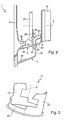
- the spokes are 7 formed in two parts.
- a first spoke part 30 is not recognizable here Place attached to the steering wheel rim 2.
- the first spoke part 30 is angled toward the axis of rotation 6, the one so angled Section then forms the support arm 26.
- a second spoke part 31 is on the one hand, e.g. via a rivet 37, firmly connected to the first spoke part 30 and attached to the hub 4 in a rotationally fixed manner via the hub plate 8.
- the connection takes place in accordance with the preferred embodiment shown here of the two spoke parts 30 and 31 so that the two spoke parts 30 and 31 on the adjacent sections almost stepless merge and align with each other.
- the second spoke part 31 has a step-shaped deformation section 32 which, from a predetermined failure value of one of the Steering wheel rim 2 yields driving force in the direction of arrow 22 and so one energy-absorbing roll bending deformation of the second spoke part 31 enables.
- the two-part design of the spokes 7 enables a suitable choice of material for the two spoke parts 30 and 31. While the first spoke part 30 be designed to transmit the failure forces to the spacer 11 can, it is expedient, the second spoke part 31 with regard to a possible optimize high energy consumption during its deformation.
- the spokes can be used in another embodiment 7 be formed in one piece and in a facing away from the steering wheel rim 2 Pick up the section. Due to this fork, the spokes 7 then a respective first leg 33 and second leg 34. During the first leg 33 is fastened to the connecting hub 4 via the hub plate 8, the second leg 34 is supported by the support ring 27 on not shown in Figure 2 Middle part 3 from. Accordingly, the second leg 34 forms in this Embodiment of the support arm 26.
- the section having the fork the spoke 7 is approximately between the connecting hub 4 or magnetic carrier 15 and the central part 3 or support ring 27 bent towards the axis of rotation 6, whereby in this Section, or in the first leg 33 again a deformation section 32 is formed, the roll bending deformation of the spoke in the event of a crash 7 enables.
- the shape of the two legs 33 and 34 can be appropriate be adapted again to their function. In the event of a crash, they can affect the Steering wheel rim 2 forces acting on the spokes 7 and their second Leg 34 on the middle part 3 or on the spacer 11 below be transmitted. As soon as the spokes 7 fail, i.e. as soon as the bending deformation the spokes 7 takes place, the spacer element 11 inevitably fails, so that the entire steering wheel unit 1 in the event of a crash with only one voltage spike gives way.
- the second leg 34 act as a driver for the Middle part 3.
- connection of the spokes 7 to the steering wheel rim 2 takes place here on Steering wheel rim 2 integrally formed lugs 35 on which the spokes 7, e.g. by Spot welds 36 are attached.
- the spacer 11 can in a special embodiment have two waisted webs 24 which extend from the ring body 23 and extend coaxially and in a circular arc to the axis of rotation 6.
- the spacer 11 here forms a crash element, the load-bearing capacity barely above what is still permitted on the steering wheel during normal operation Forces or moments.
- the training of two webs 24 a relatively large deformation path parallel to the axis of rotation 6, since the webs 24 are only squeezed so far together after a relatively large deformation path or "drove to block" are further deformations is only possible in connection with a steep increase in force.
- the failure value of the spacer 11 is smaller, preferably considerable smaller than the failure value of the spokes 7. This ensures that by taking the middle part 3 through the engaging spokes 7 the force required to cause the spokes to fail 7 is not or only insignificantly increases.
- the present invention is not limited to such an embodiment of the coupling device 5.
- the Coupling device 5 can in particular also be implemented by a gear transmission become.
Landscapes
- Engineering & Computer Science (AREA)
- Chemical & Material Sciences (AREA)
- Combustion & Propulsion (AREA)
- Transportation (AREA)
- Mechanical Engineering (AREA)
- Steering Controls (AREA)
- Air Bags (AREA)
Abstract
Description
- Figur 1 einen Längsschnitt durch eine erfindungsgemäße Lenkradeinheit bei einer ersten Ausführungsform,
- Figur 2 eine Seitenansicht auf die Lenkradeinheit, jedoch bei einer zweiten Ausführungsform
- Figur 3 eine perspektivische Ansicht auf ein Distanzelement der Lenkradeinheit bei einer besonderen Ausführungsform.
Claims (12)
- Lenkradeinheit für ein Kraftfahrzeug, insbesondere Personenkraftwagen, mitdadurch gekennzeichnet, daß der Lenkradkranz (2) über seine Speichen (7) am Mittelteil (3) zumindest in einer vom Lenkradkranz (2) zur Anschlußnabe (4) führenden Richtung abgestützt ist, wobei die Speichen (7) im Bereich ihrer Abstützung (25) drehbar am Mittelteil (3) gelagert sind.einer Anschlußnabe (4), die mit einer Lenkwelle (4a) einer Lenkungsanordnung drehfest verbindbar ist,einem Lenkradkranz (2), der über Speichen (7) drehfest mit der Anschlußnabe (4) verbunden ist,einem Mittelteil (3), das über ein Distanzelement (11) relativ zu Lenkwelle und Lenkradkranz (2) drehbar an der Anschlußnabe (4) gelagert ist, undeiner Kopplungseinrichtung (5), die das Mittelteil (3) gegenüber einer Drehbewegung des Lenkradkranzes (2) stillsetzt,wobei das Distanzelement (11) an einem Ende drehfest mit dem Mittelteil (3) verbunden ist, und am anderen Ende drehbar an der Anschlußnabe (4) gelagert ist und als Crashelement ausgebildet ist, das ab einem vorbestimmten Versagenswert einer das Mittelteil (3) in Richtung Anschlußnabe (4) antreibenden Kraft versagt,
- Lenkradeinheit nach Anspruch 1,
dadurch gekennzeichnet, daß das Mittelteil (3) einen drehfest daran angebrachten Lagerträger (19) aufweist, an dem die Speichen (7) drehbar gelagert und abgestützt sind und an dem das dem Mittelteil (3) zugewandte Ende (18) des Distanzelements (11) drehfest befestigt ist. - Lenkradeinheit nach Anspruch 1 oder 2,
dadurch gekennzeichnet, daß sich jede Speiche (7) in einem vom Lenkradkranz (2) abgewandten Abschnitt aufgabelt und einen an der Anschlußnabe (4) befestigten ersten Schenkel (33) und einen am Mittelteil (3) abgestützten und gelagerten zweiten Schenkel (34) aufweist. - Lenkradeinheit nach Anspruch 3,
dadurch gekennzeichnet, daß die Speichen (7) in einem an die Anschlußnabe (4) angrenzenden Abschnitt einen Verformungsabschnitt (32) bilden, der ab einem vorbestimmten Versagenswert einer den Lenkradkranz (2) in Richtung Anschlußnabe (4) antreibenden Kraft nachgibt, wobei der erste Schenkel (33) den Verformungsabschnitt (32) aufweist. - Lenkradeinheit nach Anspruch 1 oder 2,
dadurch gekennzeichnet, daß jede Speiche (7) zweiteilig ausgebildet ist, wobei ein erstes Speichenteil (30) am Lenkradkranz (2) befestigt und am Mittelteil (3) gelagert und abgestützt ist, wobei ein zweites Speichenteil (31) am ersten Speichenteil (30) befestigt und an der Anschlußnabe (4) befestigt ist. - Lenkradeinheit nach Anspruch 5,
dadurch gekennzeichnet, daß die Speichen (7) in einem an die Anschlußnabe (4) angrenzenden Abschnitt einen Verformungsabschnitt (32) bilden, der ab einem vorbestimmten Versagenswert einer den Lenkradkranz (2) in Richtung Anschlußnabe (4) antreibenden Kraft nachgibt, wobei das zweite Speichenteil (31) den Verformungsabschnitt (32) aufweist. - Lenkradeinheit nach Anspruch 5 oder 6,
dadurch gekennzeichnet, daß die beiden Speichenteile (30, 31) so aneinander abgestützt und befestigt sind, daß die Speichenteile (30, 31) in an diese Abstützung angrenzenden Abschnitten nahezu stufenlos ineinander übergehen. - Lenkradeinheit nach Anspruch 4 oder 6,
dadurch gekennzeichnet, daß der Versagenswert des Distanzelements (11) kleiner ist als der Versagenswert der Speichen (7). - Lenkradeinheit nach einem der Ansprüche 1 bis 8,
dadurch gekennzeichnet, daß das Distanzelement (11) an seinem der Anschlußnabe (4) zugeordneten Ende (16) als Ringkörper (23) ausgebildet ist, von dem wenigstens zwei in Umfangsrichtung des Ringkörpers (23) voneinander beabstandete Stege (24) ausgehen, die mit dem Mittelteil (3) verbunden sind. - Lenkradeinheit nach Anspruch 9,
dadurch gekennzeichnet, daß die Stege (24) mit einem Abschnitt verringerter Breite ausgebildet sind. - Lenkradeinheit nach einem der Ansprüche 1 bis 10,
dadurch gekennzeichnet, daß die Speichen (7) über einen Nabenteller (8) mit der Anschlußnabe (4) drehfest verbunden sind. - Lenkradeinheit nach einem der Ansprüche 1 bis 11,
dadurch gekennzeichnet, daß die Kopplungseinrichtung (5) ein Magnetkraftgetriebe mit wenigstens zwei Magnetanordnungen (13, 14) oder ein Zahnradgetriebe mit wenigstens zwei Zahnrädern aufweist.
Applications Claiming Priority (2)
| Application Number | Priority Date | Filing Date | Title |
|---|---|---|---|
| DE10146175 | 2001-09-19 | ||
| DE10146175A DE10146175A1 (de) | 2001-09-19 | 2001-09-19 | Lenkradeinheit für ein Kraftfahrzeug |
Publications (3)
| Publication Number | Publication Date |
|---|---|
| EP1295777A2 true EP1295777A2 (de) | 2003-03-26 |
| EP1295777A3 EP1295777A3 (de) | 2003-10-15 |
| EP1295777B1 EP1295777B1 (de) | 2006-02-22 |
Family
ID=7699549
Family Applications (1)
| Application Number | Title | Priority Date | Filing Date |
|---|---|---|---|
| EP02020564A Expired - Lifetime EP1295777B1 (de) | 2001-09-19 | 2002-09-17 | Lenkradeinheit für ein Kraftfahrzeug |
Country Status (4)
| Country | Link |
|---|---|
| US (1) | US6976404B2 (de) |
| EP (1) | EP1295777B1 (de) |
| DE (2) | DE10146175A1 (de) |
| ES (1) | ES2259061T3 (de) |
Families Citing this family (5)
| Publication number | Priority date | Publication date | Assignee | Title |
|---|---|---|---|---|
| US7040653B1 (en) | 2004-10-27 | 2006-05-09 | Automotive Technologies International, Inc. | Steering wheel assemblies for vehicles |
| JP3994830B2 (ja) * | 2002-09-04 | 2007-10-24 | 豊田合成株式会社 | ステアリングホイール |
| EP1765654A4 (de) * | 2004-03-25 | 2008-10-01 | Timken Us Corp | Lenkradbefestigungsanordnung |
| DE102016005020B4 (de) * | 2016-04-26 | 2019-08-14 | Dalphi Metal Espana, S.A. | Gassackeinheit und Fahrzeuginsassensicherheitssystem mit einer solchen Gassackeinheit sowie Herstellungsverfahren |
| US10953912B2 (en) * | 2018-03-14 | 2021-03-23 | Ford Global Technologies, Llc | Steering wheel systems and torque feedback actuator assemblies for use in steer-by-wire vehicles |
Citations (2)
| Publication number | Priority date | Publication date | Assignee | Title |
|---|---|---|---|---|
| DE4328562C1 (de) | 1993-08-25 | 1994-08-25 | Daimler Benz Ag | Lenkradanordnung für ein Kraftfahrzeug |
| DE10020085C1 (de) | 2000-04-22 | 2001-07-26 | Daimler Chrysler Ag | Lenkradeinheit für ein Kraftfahrzeug |
Family Cites Families (12)
| Publication number | Priority date | Publication date | Assignee | Title |
|---|---|---|---|---|
| DE1912528B2 (de) * | 1969-03-12 | 1975-01-23 | Volkswagenwerk Ag, 3180 Wolfsburg | Sicherheitslenkrad für Kraftfahrzeuge |
| DE2614041A1 (de) * | 1976-04-01 | 1977-10-06 | Petri Ag | Energieabsorptionselement |
| DE2842020C2 (de) * | 1978-09-27 | 1986-03-13 | Bernd 5000 Köln Pilatzki | Lenkvorrichtung für Kraftfahrzeuge mit einem Pralltopf |
| DE2935936C2 (de) * | 1979-09-06 | 1983-10-20 | Daimler-Benz Ag, 7000 Stuttgart | Lenkrad für Kraftwagen |
| DE3048771C2 (de) * | 1980-01-29 | 1983-06-23 | Ford-Werke AG, 5000 Köln | Energieabsorbierendes Lenkrad für Kraftfahrzeuge |
| DE3013996A1 (de) * | 1980-04-11 | 1981-10-22 | Bernd 5000 Köln Pilatzki | Lenkvorrichtung fuer kraftfahrzeuge mit einem pralltopf |
| DE3621226C1 (de) * | 1986-06-25 | 1988-01-14 | Daimler Benz Ag | Lenkradanordnung fuer Fahrzeuge |
| JPH0632460Y2 (ja) * | 1987-12-25 | 1994-08-24 | 豊田合成株式会社 | 衝撃エネルギー吸収ステアリングホイール |
| DE19714898A1 (de) | 1997-04-03 | 1998-10-08 | Petri Ag | Lenkrad |
| DE19714838C2 (de) | 1997-04-10 | 2002-10-10 | Rittal Gmbh & Co Kg | Schaltschrankklimatisierungseinrichtung |
| DE19747665C2 (de) * | 1997-10-29 | 2000-05-18 | Mannesmann Vdo Ag | Lenkrad mit einem Lenkradtopf |
| DE20021532U1 (de) * | 2000-12-20 | 2001-04-26 | TRW Automotive Safety Systems GmbH & Co. KG, 63743 Aschaffenburg | Fahrzeuglenkrad |
-
2001
- 2001-09-19 DE DE10146175A patent/DE10146175A1/de not_active Withdrawn
-
2002
- 2002-09-17 EP EP02020564A patent/EP1295777B1/de not_active Expired - Lifetime
- 2002-09-17 DE DE50205858T patent/DE50205858D1/de not_active Expired - Fee Related
- 2002-09-17 ES ES02020564T patent/ES2259061T3/es not_active Expired - Lifetime
- 2002-09-19 US US10/247,382 patent/US6976404B2/en not_active Expired - Fee Related
Patent Citations (2)
| Publication number | Priority date | Publication date | Assignee | Title |
|---|---|---|---|---|
| DE4328562C1 (de) | 1993-08-25 | 1994-08-25 | Daimler Benz Ag | Lenkradanordnung für ein Kraftfahrzeug |
| DE10020085C1 (de) | 2000-04-22 | 2001-07-26 | Daimler Chrysler Ag | Lenkradeinheit für ein Kraftfahrzeug |
Also Published As
| Publication number | Publication date |
|---|---|
| EP1295777A3 (de) | 2003-10-15 |
| EP1295777B1 (de) | 2006-02-22 |
| DE50205858D1 (de) | 2006-04-27 |
| US6976404B2 (en) | 2005-12-20 |
| ES2259061T3 (es) | 2006-09-16 |
| US20030075004A1 (en) | 2003-04-24 |
| DE10146175A1 (de) | 2003-04-17 |
Similar Documents
| Publication | Publication Date | Title |
|---|---|---|
| EP0943525B1 (de) | Lenksäulenanordnung für ein Kraftfahrzeug | |
| DE19526769C2 (de) | Verfahren zur Herstellung einer stoßabsorbierenden Lenkwelle | |
| DE102018113037B4 (de) | Lenkvorrichtung für fahrzeug | |
| EP0659615A1 (de) | Pedalwerk für ein Fahrzeug | |
| EP3938268B1 (de) | Verstellantrieb für eine lenksäule und lenksäule für ein kraftfahrzeug | |
| EP3353040B1 (de) | Einstellbare lenksaeule fuer ein kraftfahrzeug | |
| DE2431883B2 (de) | Lenksäule für Kraftfahrzeuge | |
| DE3136812C2 (de) | Lenksäulenverkleidung für Fahrzeuge | |
| DE10033810A1 (de) | Lenksäule eines Kraftfahrzeuges | |
| EP0572821B1 (de) | Kraftfahrzeuglenksäule | |
| DE1912528B2 (de) | Sicherheitslenkrad für Kraftfahrzeuge | |
| EP2807071B1 (de) | Lenksäule für ein kraftfahrzeug | |
| DE7902092U1 (de) | Lenksäule für Kraftfahrzeuge | |
| DE2143935C3 (de) | Konsole zum Tragen der Lenksäule einer Kraftfahrzeugsicherheitslenkung | |
| DE2150061B2 (de) | Aus Blech bestehendes, piatisch verformbares Deformationsglied für Sicherheitslenkungen von Kraftfahrzeugen | |
| EP1295777B1 (de) | Lenkradeinheit für ein Kraftfahrzeug | |
| DE2657485A1 (de) | Sicherheitslenkspindel fuer fahrzeuge, insbesondere kraftfahrzeuge | |
| DE2640770A1 (de) | Servoeinrichtung | |
| DE2318385A1 (de) | Einrichtung zur absorption von energie durch plastische verformung | |
| EP2205475A1 (de) | Lenksäulenanordnung für kraftwagen | |
| EP2993076B1 (de) | Beschlag und fahrzeugsitz | |
| DE102023104998A1 (de) | Längenverstellbare Bedieneinheit | |
| DE102006003430A1 (de) | Lenksäule mit feststehender Lenkradnabe und Verstellbarkeit des Lenkrades im Crashfall | |
| DE102016212812A1 (de) | Lenkung für ein Kraftfahrzeug, insbesondere für ein Nutzfahrzeug, mit Lenkwelle und Kugelgewindemutter | |
| EP3987199B1 (de) | Kopplungselement zur anbringung an einer gewindespindel, system mit einer gewindespindel und einem kopplungselement, spindeltrieb und lenksäule |
Legal Events
| Date | Code | Title | Description |
|---|---|---|---|
| PUAI | Public reference made under article 153(3) epc to a published international application that has entered the european phase |
Free format text: ORIGINAL CODE: 0009012 |
|
| AK | Designated contracting states |
Kind code of ref document: A2 Designated state(s): AT BE BG CH CY CZ DE DK EE ES FI FR GB GR IE IT LI LU MC NL PT SE SK TR |
|
| AX | Request for extension of the european patent |
Extension state: AL LT LV MK RO SI |
|
| PUAL | Search report despatched |
Free format text: ORIGINAL CODE: 0009013 |
|
| AK | Designated contracting states |
Kind code of ref document: A3 Designated state(s): AT BE BG CH CY CZ DE DK EE ES FI FR GB GR IE IT LI LU MC NL PT SE SK TR |
|
| AX | Request for extension of the european patent |
Extension state: AL LT LV MK RO SI |
|
| 17P | Request for examination filed |
Effective date: 20040304 |
|
| AKX | Designation fees paid |
Designated state(s): DE ES FR GB IT |
|
| 17Q | First examination report despatched |
Effective date: 20040817 |
|
| GRAP | Despatch of communication of intention to grant a patent |
Free format text: ORIGINAL CODE: EPIDOSNIGR1 |
|
| GRAS | Grant fee paid |
Free format text: ORIGINAL CODE: EPIDOSNIGR3 |
|
| GRAA | (expected) grant |
Free format text: ORIGINAL CODE: 0009210 |
|
| RAP1 | Party data changed (applicant data changed or rights of an application transferred) |
Owner name: TRW AUTOMOTIVE SAFETY SYSTEMS GMBH |
|
| AK | Designated contracting states |
Kind code of ref document: B1 Designated state(s): DE ES FR GB IT |
|
| PG25 | Lapsed in a contracting state [announced via postgrant information from national office to epo] |
Ref country code: GB Free format text: LAPSE BECAUSE OF FAILURE TO SUBMIT A TRANSLATION OF THE DESCRIPTION OR TO PAY THE FEE WITHIN THE PRESCRIBED TIME-LIMIT Effective date: 20060222 |
|
| REG | Reference to a national code |
Ref country code: GB Ref legal event code: FG4D Free format text: NOT ENGLISH |
|
| REF | Corresponds to: |
Ref document number: 50205858 Country of ref document: DE Date of ref document: 20060427 Kind code of ref document: P |
|
| REG | Reference to a national code |
Ref country code: ES Ref legal event code: FG2A Ref document number: 2259061 Country of ref document: ES Kind code of ref document: T3 |
|
| GBV | Gb: ep patent (uk) treated as always having been void in accordance with gb section 77(7)/1977 [no translation filed] |
Effective date: 20060222 |
|
| ET | Fr: translation filed | ||
| PLBE | No opposition filed within time limit |
Free format text: ORIGINAL CODE: 0009261 |
|
| STAA | Information on the status of an ep patent application or granted ep patent |
Free format text: STATUS: NO OPPOSITION FILED WITHIN TIME LIMIT |
|
| 26N | No opposition filed |
Effective date: 20061123 |
|
| PGFP | Annual fee paid to national office [announced via postgrant information from national office to epo] |
Ref country code: ES Payment date: 20070920 Year of fee payment: 6 |
|
| PGFP | Annual fee paid to national office [announced via postgrant information from national office to epo] |
Ref country code: DE Payment date: 20070928 Year of fee payment: 6 Ref country code: IT Payment date: 20070913 Year of fee payment: 6 |
|
| PGFP | Annual fee paid to national office [announced via postgrant information from national office to epo] |
Ref country code: FR Payment date: 20070904 Year of fee payment: 6 |
|
| REG | Reference to a national code |
Ref country code: FR Ref legal event code: ST Effective date: 20090529 |
|
| PG25 | Lapsed in a contracting state [announced via postgrant information from national office to epo] |
Ref country code: IT Free format text: LAPSE BECAUSE OF NON-PAYMENT OF DUE FEES Effective date: 20080917 Ref country code: DE Free format text: LAPSE BECAUSE OF NON-PAYMENT OF DUE FEES Effective date: 20090401 |
|
| PG25 | Lapsed in a contracting state [announced via postgrant information from national office to epo] |
Ref country code: FR Free format text: LAPSE BECAUSE OF NON-PAYMENT OF DUE FEES Effective date: 20080930 |
|
| REG | Reference to a national code |
Ref country code: ES Ref legal event code: FD2A Effective date: 20080918 |
|
| PG25 | Lapsed in a contracting state [announced via postgrant information from national office to epo] |
Ref country code: ES Free format text: LAPSE BECAUSE OF NON-PAYMENT OF DUE FEES Effective date: 20080918 |