EP1295061B1 - Braided hose reinforcement and method of manufacture - Google Patents
Braided hose reinforcement and method of manufacture Download PDFInfo
- Publication number
- EP1295061B1 EP1295061B1 EP01943317A EP01943317A EP1295061B1 EP 1295061 B1 EP1295061 B1 EP 1295061B1 EP 01943317 A EP01943317 A EP 01943317A EP 01943317 A EP01943317 A EP 01943317A EP 1295061 B1 EP1295061 B1 EP 1295061B1
- Authority
- EP
- European Patent Office
- Prior art keywords
- steel wires
- side regions
- wires
- tensile strength
- strips
- Prior art date
- Legal status (The legal status is an assumption and is not a legal conclusion. Google has not performed a legal analysis and makes no representation as to the accuracy of the status listed.)
- Expired - Lifetime
Links
- 230000002787 reinforcement Effects 0.000 title claims abstract description 31
- 238000004519 manufacturing process Methods 0.000 title claims description 4
- 238000000034 method Methods 0.000 title claims description 3
- 229910000831 Steel Inorganic materials 0.000 claims abstract description 67
- 239000010959 steel Substances 0.000 claims abstract description 67
- 229910052799 carbon Inorganic materials 0.000 claims description 7
- OKTJSMMVPCPJKN-UHFFFAOYSA-N Carbon Chemical compound [C] OKTJSMMVPCPJKN-UHFFFAOYSA-N 0.000 claims description 6
- 238000009954 braiding Methods 0.000 claims description 2
- 229910001369 Brass Inorganic materials 0.000 description 3
- 239000010951 brass Substances 0.000 description 3
- 230000000694 effects Effects 0.000 description 3
- 229910052751 metal Inorganic materials 0.000 description 3
- 239000002184 metal Substances 0.000 description 3
- 229910000975 Carbon steel Inorganic materials 0.000 description 2
- PXHVJJICTQNCMI-UHFFFAOYSA-N Nickel Chemical compound [Ni] PXHVJJICTQNCMI-UHFFFAOYSA-N 0.000 description 2
- 239000010962 carbon steel Substances 0.000 description 2
- 238000000576 coating method Methods 0.000 description 2
- 229920001971 elastomer Polymers 0.000 description 2
- 239000012530 fluid Substances 0.000 description 2
- 230000003014 reinforcing effect Effects 0.000 description 2
- VYZAMTAEIAYCRO-UHFFFAOYSA-N Chromium Chemical compound [Cr] VYZAMTAEIAYCRO-UHFFFAOYSA-N 0.000 description 1
- RYGMFSIKBFXOCR-UHFFFAOYSA-N Copper Chemical compound [Cu] RYGMFSIKBFXOCR-UHFFFAOYSA-N 0.000 description 1
- 229910000742 Microalloyed steel Inorganic materials 0.000 description 1
- ZOKXTWBITQBERF-UHFFFAOYSA-N Molybdenum Chemical compound [Mo] ZOKXTWBITQBERF-UHFFFAOYSA-N 0.000 description 1
- HCHKCACWOHOZIP-UHFFFAOYSA-N Zinc Chemical compound [Zn] HCHKCACWOHOZIP-UHFFFAOYSA-N 0.000 description 1
- 229910045601 alloy Inorganic materials 0.000 description 1
- 239000000956 alloy Substances 0.000 description 1
- 229910052804 chromium Inorganic materials 0.000 description 1
- 239000011651 chromium Substances 0.000 description 1
- 229910017052 cobalt Inorganic materials 0.000 description 1
- 239000010941 cobalt Substances 0.000 description 1
- GUTLYIVDDKVIGB-UHFFFAOYSA-N cobalt atom Chemical compound [Co] GUTLYIVDDKVIGB-UHFFFAOYSA-N 0.000 description 1
- 229910052802 copper Inorganic materials 0.000 description 1
- 239000010949 copper Substances 0.000 description 1
- 239000000806 elastomer Substances 0.000 description 1
- 239000007789 gas Substances 0.000 description 1
- 238000010438 heat treatment Methods 0.000 description 1
- 230000006698 induction Effects 0.000 description 1
- 229910052748 manganese Inorganic materials 0.000 description 1
- 150000002739 metals Chemical class 0.000 description 1
- 229910052750 molybdenum Inorganic materials 0.000 description 1
- 239000011733 molybdenum Substances 0.000 description 1
- 229910052759 nickel Inorganic materials 0.000 description 1
- 229920000642 polymer Polymers 0.000 description 1
- 238000000926 separation method Methods 0.000 description 1
- 229910052720 vanadium Inorganic materials 0.000 description 1
- LEONUFNNVUYDNQ-UHFFFAOYSA-N vanadium atom Chemical compound [V] LEONUFNNVUYDNQ-UHFFFAOYSA-N 0.000 description 1
- 229910052725 zinc Inorganic materials 0.000 description 1
- 239000011701 zinc Substances 0.000 description 1
Images
Classifications
-
- D—TEXTILES; PAPER
- D04—BRAIDING; LACE-MAKING; KNITTING; TRIMMINGS; NON-WOVEN FABRICS
- D04C—BRAIDING OR MANUFACTURE OF LACE, INCLUDING BOBBIN-NET OR CARBONISED LACE; BRAIDING MACHINES; BRAID; LACE
- D04C1/00—Braid or lace, e.g. pillow-lace; Processes for the manufacture thereof
- D04C1/06—Braid or lace serving particular purposes
-
- F—MECHANICAL ENGINEERING; LIGHTING; HEATING; WEAPONS; BLASTING
- F16—ENGINEERING ELEMENTS AND UNITS; GENERAL MEASURES FOR PRODUCING AND MAINTAINING EFFECTIVE FUNCTIONING OF MACHINES OR INSTALLATIONS; THERMAL INSULATION IN GENERAL
- F16L—PIPES; JOINTS OR FITTINGS FOR PIPES; SUPPORTS FOR PIPES, CABLES OR PROTECTIVE TUBING; MEANS FOR THERMAL INSULATION IN GENERAL
- F16L11/00—Hoses, i.e. flexible pipes
- F16L11/04—Hoses, i.e. flexible pipes made of rubber or flexible plastics
- F16L11/08—Hoses, i.e. flexible pipes made of rubber or flexible plastics with reinforcements embedded in the wall
- F16L11/085—Hoses, i.e. flexible pipes made of rubber or flexible plastics with reinforcements embedded in the wall comprising one or more braided layers
-
- F—MECHANICAL ENGINEERING; LIGHTING; HEATING; WEAPONS; BLASTING
- F16—ENGINEERING ELEMENTS AND UNITS; GENERAL MEASURES FOR PRODUCING AND MAINTAINING EFFECTIVE FUNCTIONING OF MACHINES OR INSTALLATIONS; THERMAL INSULATION IN GENERAL
- F16L—PIPES; JOINTS OR FITTINGS FOR PIPES; SUPPORTS FOR PIPES, CABLES OR PROTECTIVE TUBING; MEANS FOR THERMAL INSULATION IN GENERAL
- F16L11/00—Hoses, i.e. flexible pipes
- F16L11/04—Hoses, i.e. flexible pipes made of rubber or flexible plastics
- F16L11/10—Hoses, i.e. flexible pipes made of rubber or flexible plastics with reinforcements not embedded in the wall
-
- D—TEXTILES; PAPER
- D10—INDEXING SCHEME ASSOCIATED WITH SUBLASSES OF SECTION D, RELATING TO TEXTILES
- D10B—INDEXING SCHEME ASSOCIATED WITH SUBLASSES OF SECTION D, RELATING TO TEXTILES
- D10B2101/00—Inorganic fibres
- D10B2101/20—Metallic fibres
-
- D—TEXTILES; PAPER
- D10—INDEXING SCHEME ASSOCIATED WITH SUBLASSES OF SECTION D, RELATING TO TEXTILES
- D10B—INDEXING SCHEME ASSOCIATED WITH SUBLASSES OF SECTION D, RELATING TO TEXTILES
- D10B2505/00—Industrial
- D10B2505/02—Reinforcing materials; Prepregs
-
- Y—GENERAL TAGGING OF NEW TECHNOLOGICAL DEVELOPMENTS; GENERAL TAGGING OF CROSS-SECTIONAL TECHNOLOGIES SPANNING OVER SEVERAL SECTIONS OF THE IPC; TECHNICAL SUBJECTS COVERED BY FORMER USPC CROSS-REFERENCE ART COLLECTIONS [XRACs] AND DIGESTS
- Y10—TECHNICAL SUBJECTS COVERED BY FORMER USPC
- Y10S—TECHNICAL SUBJECTS COVERED BY FORMER USPC CROSS-REFERENCE ART COLLECTIONS [XRACs] AND DIGESTS
- Y10S138/00—Pipes and tubular conduits
- Y10S138/05—Pre-stress
-
- Y—GENERAL TAGGING OF NEW TECHNOLOGICAL DEVELOPMENTS; GENERAL TAGGING OF CROSS-SECTIONAL TECHNOLOGIES SPANNING OVER SEVERAL SECTIONS OF THE IPC; TECHNICAL SUBJECTS COVERED BY FORMER USPC CROSS-REFERENCE ART COLLECTIONS [XRACs] AND DIGESTS
- Y10—TECHNICAL SUBJECTS COVERED BY FORMER USPC
- Y10T—TECHNICAL SUBJECTS COVERED BY FORMER US CLASSIFICATION
- Y10T428/00—Stock material or miscellaneous articles
- Y10T428/13—Hollow or container type article [e.g., tube, vase, etc.]
- Y10T428/1352—Polymer or resin containing [i.e., natural or synthetic]
- Y10T428/139—Open-ended, self-supporting conduit, cylinder, or tube-type article
- Y10T428/1393—Multilayer [continuous layer]
Definitions
- the invention relates to a braided hose reinforcement.
- Hoses for example hydraulic and pneumatic hoses, conventionally comprise a flexible inner tube, such as a rubber or plastic inner tube surrounded by one or more tubular braids of metal wires. Since these hoses are used for conveying high pressure fluids or gases, they have to withstand the forces of the pressure within the hose. In order to obtain a high impulse strength, high strength carbon steel wires are utilized as reinforcing elements. In a still continuing effort to save weight of a hose reinforcement and to increase the flexibility, there is a trend to use wires with a higher tensile strength. However, because of the high internal pressure, high transversal stresses are applied on the reinforcing elements. This has as consequence that the hose can not be utilized at its full strength.
- the strips can be braided in such a way that the braided structure does not provide 100 % coverage of the inner tube but for example only 80 or 85 % coverage.
- the separation between adjacent strips permits some freedom of movement of the wires during flexing and/or application of fluid pressure to the hose and results in good stress transfer from wire to wire.
- Other ways to minimize the stresses applied on the wires is to provide a hose reinforcement which comprises several superimposed layers of wires. Such reinforcement structures, however, have the disadvantage of a higher weight.
- a braided hose reinforcement comprises a number of left and right turning strips.
- the left turning strips are bent in such a way that they subsequently run above and under the right turning strips; while the right turning strips are bent so that they subsequently run above and under the left turning strips.
- Each of the strips comprises a number of steel wires arranged in adjoining parallel relation so that each strip is substantially flat.
- a strip has a longitudinal central region and two longitudinal side regions. Each of these central and side regions comprises one or more steel wires.
- a strip comprises preferably between four and ten steel wires, more preferably a strip comprises between six and eight wires.
- the number of steel wires in the side regions is one; while the number of steel wires of the central region ranges between four and six.
- the steel wires preferably have a diameter between 0.10 and 0.90 mm, for example 0.20 mm.
- the steel wires of the side regions and the steel wires of the central region may all have the same diameter.
- the wires may be round wires or they may be flattened, for example to wires having a rectangular cross-section or a rectangular cross-section with rounded edges.
- the steel wires incorporated in the hoses preferably have a carbon content between 0.70 % and 1.20 % and a tensile strength between 2150 and 4000 N/mm 2 .
- each strip passes alternately over and under a transversely directed strip, the wires are deformed. Consequently, stresses are created on the wires, more particularly on the segments of the wires between adjacent overlying and underlying transverse strips. The stresses created in each segment will depend on the level of pinching exerted by the wires lying over and under the wire. This pinching gives rise to a rather complex form of stress, which is not simply tensile or traction, but is also including transversal forces on certain points along the wires.
- the steel wire or steel wires of the side regions have a tensile strength which is substantially lower than the tensile strength of the steel wire or steel wires of the central region.
- the steel wire or steel wires of the side regions may withstand the stresses to a higher degree since they have a higher ductility.
- the steel wire or steel wires of the side regions of a strip have a tensile strength which is at least 10 % lower than the tensile strength of the steel wire or steel wires of the central region. More preferably, the steel wire or steel wires of the side regions have a tensile strength which is at least 20 % lower than the tensile strength of the steel wire or steel wires of the central regions
- the steel wire or steel wires of the central region preferably have a tensile strength higher than 2150 MPa; more preferably the tensile strength is higher than 2800 MPa.
- Wires suitable to be used as wires for the side regions are for example stress-relieved wires. These stress-relieved wires preferably have an elongation at rupture exceeding 4 %.
- the steel wire or steel wires of the side regions can be wires having a lower carbon content than the steel wire or steel wires of the central region.
- the carbon content of the steel wire or steel wires of the side regions is for example lower than 0.80 %.
- the steel wire or steel wires of the side regions of a strip are flat wires or wires with a rectangular cross-section.
- the steel wires may be coated to assure satisfactory adhesion to the elastomer of the hose.
- Suitable coatings are copper or zinc or coatings comprising an alloy of these metals, such as brass.
- the braided hose reinforcement may comprise steel wires arranged in one layer or may comprise multiple layers.
- hose reinforcement comprises more layers a thin polymer layer may be present between two different layers to provide stress transfer from one layer to the other.
- a hose, pipe or tube comprising a hose reinforcement as described above is provided.
- a method of manufacturing a hose reinforcement comprises the steps of
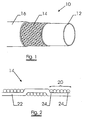
- Figure 1 shows a flexible hose 10.
- the hose comprises:
- FIG. 2 shows the cross-section of the reinforcement structure 14.
- the reinforcement structure comprises strips 20 passing alternately over and under transversely directed strips 22.
- a strip comprises 6 steel wires having a diameter between 0.10 and 0.90 mm. All steel wires of the strip have the same diameter
- the side regions of the strip comprise one wire, whereas the central region of the strip comprises 4 wires.
- the steel wires of the central region are for example carbon steel wires with a carbon content between 0.70 % an 1.20 %.
- high carbon micro-alloyed steel comprising from 0.70 % to 1.20 % C, 0.10 to 1.2 % Mn and up to 0.40 % of chromium, cobalt, molybdenum, nickel, and/or vanadium can be used.
- the tensile strength of the wires is preferably higher than 2800 N/mm 2 .
- the steel wires can be coated with a brass layer.
- the steel wires of the side regions 24 are stress-relieved steel wires.
- a stress-relieved wire suitable to be used as a wire of the side regions of a strip may be obtained as follows :
- the wires of the side regions are replaced by wires having a tensile strength of 2500 N/mm 2 .
- the deformation and stresses created on the wires of the side regions of a strip 24 are more pronounced than those created on an inner wire due to the pinching effect of the adjacent underlying and overlying transverse strip.
- the strips may withstand the stresses to a higher degree.
Landscapes
- Engineering & Computer Science (AREA)
- General Engineering & Computer Science (AREA)
- Mechanical Engineering (AREA)
- Manufacturing & Machinery (AREA)
- Textile Engineering (AREA)
- Rigid Pipes And Flexible Pipes (AREA)
- Moulding By Coating Moulds (AREA)
- Processing And Handling Of Plastics And Other Materials For Molding In General (AREA)
Abstract
Description
- The invention relates to a braided hose reinforcement.
- Hoses, for example hydraulic and pneumatic hoses, conventionally comprise a flexible inner tube, such as a rubber or plastic inner tube surrounded by one or more tubular braids of metal wires.
Since these hoses are used for conveying high pressure fluids or gases, they have to withstand the forces of the pressure within the hose.
In order to obtain a high impulse strength, high strength carbon steel wires are utilized as reinforcing elements.
In a still continuing effort to save weight of a hose reinforcement and to increase the flexibility, there is a trend to use wires with a higher tensile strength.
However, because of the high internal pressure, high transversal stresses are applied on the reinforcing elements. This has as consequence that the hose can not be utilized at its full strength. - To minimize the stresses on the wires, the strips can be braided in such a way that the braided structure does not provide 100 % coverage of the inner tube but for example only 80 or 85 % coverage. The separation between adjacent strips permits some freedom of movement of the wires during flexing and/or application of fluid pressure to the hose and results in good stress transfer from wire to wire.
Other ways to minimize the stresses applied on the wires is to provide a hose reinforcement which comprises several superimposed layers of wires. Such reinforcement structures, however, have the disadvantage of a higher weight. - It is an object of the present invention to provide a braided hose reinforcement with an increased strength and endurance.
- It is also an object of the invention to decrease the weight and to increase the flexibility of a hose reinforcement white maintaining a high strength.
- According to a first aspect of the invention, a braided hose reinforcement is provided. The hose reinforcement comprises a number of left and right turning strips. The left turning strips are bent in such a way that they subsequently run above and under the right turning strips; while the right turning strips are bent so that they subsequently run above and under the left turning strips.
- Each of the strips comprises a number of steel wires arranged in adjoining parallel relation so that each strip is substantially flat.
A strip has a longitudinal central region and two longitudinal side regions. Each of these central and side regions comprises one or more steel wires. - A strip comprises preferably between four and ten steel wires, more preferably a strip comprises between six and eight wires.
In a preferred embodiment the number of steel wires in the side regions is one; while the number of steel wires of the central region ranges between four and six. - The steel wires preferably have a diameter between 0.10 and 0.90 mm, for example 0.20 mm.
- The steel wires of the side regions and the steel wires of the central region may all have the same diameter.
- The wires may be round wires or they may be flattened, for example to wires having a rectangular cross-section or a rectangular cross-section with rounded edges.
- The steel wires incorporated in the hoses preferably have a carbon content between 0.70 % and 1.20 % and a tensile strength between 2150 and 4000 N/mm2.
- Since each strip passes alternately over and under a transversely directed strip, the wires are deformed.
Consequently, stresses are created on the wires, more particularly on the segments of the wires between adjacent overlying and underlying transverse strips.
The stresses created in each segment will depend on the level of pinching exerted by the wires lying over and under the wire.
This pinching gives rise to a rather complex form of stress, which is not simply tensile or traction, but is also including transversal forces on certain points along the wires. - The wires of the side regions of a strip suffer most from this pinching effect.
- It has been shown that transversal forces have a negative impact on the breaking load of a metal wire.
Consequently, due to the pinching effect, creating transversal contact stresses, the high tensile wire can not be used at its full potential.
This means that the full strength of the hose remains limited although high tensile wire is used. - Therefore, according to the present invention, the steel wire or steel wires of the side regions have a tensile strength which is substantially lower than the tensile strength of the steel wire or steel wires of the central region. The steel wire or steel wires of the side regions may withstand the stresses to a higher degree since they have a higher ductility.
- Preferably, the steel wire or steel wires of the side regions of a strip have a tensile strength which is at least 10 % lower than the tensile strength of the steel wire or steel wires of the central region.
More preferably, the steel wire or steel wires of the side regions have a tensile strength which is at least 20 % lower than the tensile strength of the steel wire or steel wires of the central regions - The steel wire or steel wires of the central region preferably have a tensile strength higher than 2150 MPa; more preferably the tensile strength is higher than 2800 MPa..
- Wires suitable to be used as wires for the side regions are for example stress-relieved wires.
These stress-relieved wires preferably have an elongation at rupture exceeding 4 %. - Alternatively, the steel wire or steel wires of the side regions can be wires having a lower carbon content than the steel wire or steel wires of the central region.
The carbon content of the steel wire or steel wires of the side regions is for example lower than 0.80 %. - It can be preferred that the steel wire or steel wires of the side regions of a strip are flat wires or wires with a rectangular cross-section.
- The steel wires may be coated to assure satisfactory adhesion to the elastomer of the hose.
Suitable coatings are copper or zinc or coatings comprising an alloy of these metals, such as brass. - The braided hose reinforcement may comprise steel wires arranged in one layer or may comprise multiple layers.
- In case the hose reinforcement comprises more layers a thin polymer layer may be present between two different layers to provide stress transfer from one layer to the other.
- According to a second aspect of the invention a hose, pipe or tube comprising a hose reinforcement as described above is provided.
- According to a further aspect of the invention a method of manufacturing a hose reinforcement is provided.
The method comprises the steps of - providing a number of strips; each strip having a longitudinal central portion and two longitudinal side regions; each of said central and side regions comprising one or more steel wires; said one or more steel wires of said side regions having a tensile strength which is substantially lower than the tensile strength of said one or more steel wires of said central region;
- braiding said strips to form the reinforcement.
- It is clear that all embodiments of strips described above can be considered for the manufacturing of the hose reinforcement.
- The invention will now be described into more detail with reference to the accompanying drawings wherein
- FIGURE 1 shows a reinforced hose according to the present invention;
- FIGURE 2 is the cross-section of the reinforcement shown in figure 1.
- Figure 1 shows a
flexible hose 10.
The hose comprises: - an
inner tube 12; - a
reinforcement structure 14, comprising at least one tubular braid; - an
outer cover 16. - Figure 2 shows the cross-section of the
reinforcement structure 14. The reinforcement structure comprisesstrips 20 passing alternately over and under transversely directed strips 22.
A strip comprises 6 steel wires having a diameter between 0.10 and 0.90 mm. All steel wires of the strip have the same diameter
The side regions of the strip comprise one wire, whereas the central region of the strip comprises 4 wires. - The steel wires of the central region are for example carbon steel wires with a carbon content between 0.70 % an 1.20 %. Also high carbon micro-alloyed steel comprising from 0.70 % to 1.20 % C, 0.10 to 1.2 % Mn and up to 0.40 % of chromium, cobalt, molybdenum, nickel, and/or vanadium can be used.
The tensile strength of the wires is preferably higher than 2800 N/mm2. The steel wires can be coated with a brass layer. - The steel wires of the
side regions 24 are stress-relieved steel wires. - A stress-relieved wire suitable to be used as a wire of the side regions of a strip may be obtained as follows :
- A steel wire or a steel wire coated with a layer of brass is drawn until a final diameter between 0.10 and 0.90 mm and a tensile strength Rm of about 2800 to 3600 N/mm2.
- The drawn steel wire is then subjected to a stress-relieving treatment, e.g. by passing the wire through a high-frequency or mid-frequency induction coil, heating the wire to a temperature of 300 to 450 °C.
- In another embodiment, the wires of the side regions are replaced by wires having a tensile strength of 2500 N/mm2.
- The deformation and stresses created on the wires of the side regions of a
strip 24 are more pronounced than those created on an inner wire due to the pinching effect of the adjacent underlying and overlying transverse strip.
By replacing the wires of the side regions of the strips with wires characterised by a tensile strength which is substantially lower than the tensile strength of the wires of the central region, the strips may withstand the stresses to a higher degree.
Claims (10)
- A braided hose reinforcement comprising left and right turning strips, said left turning strips being bent so that they subsequently run above and under said right turning strips and vice versa, each of said strips having a longitudinal central region and two longitudinal side regions; each of said central and side regions comprising one or more steel wires, characterised in that said one or more steel wires of said side regions have a tensile strength which is substantially lower than the tensile strength of said one or more steel wires of said central region, said one or more steel wires of said side regions and said one or more steel wires of said central region all having the same diameter.
- A hose reinforcement according to claim 1, wherein said one or more steel wires of said side regions have a tensile strength which is at least 10 % lower than the tensile strength of said one or more steel wires of said central region.
- A hose reinforcement according to claim 1 or 3, wherein said one or more steel wires of said side regions are stress-relieved.
- A hose reinforcement according to claim 4, wherein said stress-relieved wires have an elongation at rupture exceeding 4 %.
- A hose reinforcement according to any one of the preceding claims, wherein said one or more steel wires of the side regions have a carbon content lower than 0.80 %.
- A hose reinforcement according to any one of the preceding claims, wherein said one or more steel wires of said side regions are flat wires or wires with a rectangular cross-section.
- A hose reinforcement according to any one of the preceding claims, wherein the number of the steel wires in said side regions equals one.
- A hose reinforcement according to any one of the preceding claims, wherein the steel wire in the central region have a tensile strength higher than 2800 MPa.
- A hose, pipe or tube comprising a hose reinforcement according to any one of claims 1 to 8.
- A method of manufacturing a hose reinforcement according to any one of claims 1 to 8, said method comprises the steps of- providing a number of strips; each strip having a longitudinal central portion and two longitudinal side regions; each of said central and side regions comprising one or more steel wires; said one or more steel wires of said side regions having a tensile strength which is substantially lower than the tensile strength of said one or more steel wires of said central region; said one or more steel wires of said side regions and said on a more steel wires of said central region all having the same diameter- braiding said strips to form the reinforcement.
Priority Applications (1)
| Application Number | Priority Date | Filing Date | Title |
|---|---|---|---|
| EP01943317A EP1295061B1 (en) | 2000-05-31 | 2001-05-04 | Braided hose reinforcement and method of manufacture |
Applications Claiming Priority (4)
| Application Number | Priority Date | Filing Date | Title |
|---|---|---|---|
| EP00201942 | 2000-05-31 | ||
| EP00201942 | 2000-05-31 | ||
| PCT/EP2001/005019 WO2001092770A1 (en) | 2000-05-31 | 2001-05-04 | Braided hose reinforcement and method of manufacture |
| EP01943317A EP1295061B1 (en) | 2000-05-31 | 2001-05-04 | Braided hose reinforcement and method of manufacture |
Publications (2)
| Publication Number | Publication Date |
|---|---|
| EP1295061A1 EP1295061A1 (en) | 2003-03-26 |
| EP1295061B1 true EP1295061B1 (en) | 2006-04-05 |
Family
ID=8171586
Family Applications (1)
| Application Number | Title | Priority Date | Filing Date |
|---|---|---|---|
| EP01943317A Expired - Lifetime EP1295061B1 (en) | 2000-05-31 | 2001-05-04 | Braided hose reinforcement and method of manufacture |
Country Status (8)
| Country | Link |
|---|---|
| US (1) | US6883551B2 (en) |
| EP (1) | EP1295061B1 (en) |
| JP (1) | JP4783538B2 (en) |
| AT (1) | ATE322641T1 (en) |
| AU (1) | AU2001265922A1 (en) |
| BR (1) | BR0111122B1 (en) |
| DE (1) | DE60118561T2 (en) |
| WO (1) | WO2001092770A1 (en) |
Cited By (1)
| Publication number | Priority date | Publication date | Assignee | Title |
|---|---|---|---|---|
| US8783300B2 (en) | 2009-08-14 | 2014-07-22 | Kongsberg Actuation Systems Ii, Inc. | Hose assembly and method of forming the same |
Families Citing this family (13)
| Publication number | Priority date | Publication date | Assignee | Title |
|---|---|---|---|---|
| FR2845922A1 (en) | 2002-10-21 | 2004-04-23 | Robert Schegerin | Aircraft pilot respirator mask tube has rigid structure connected to seat or cockpit to take weight of supple conduit |
| DE10329857B3 (en) * | 2003-07-02 | 2004-12-30 | Verta Ag | Protection system for elongated bodies, especially wiring harnesses, cabels or pipes, comprises layers of glass and aramid fibers, aramid fibers and metal fibers |
| GB0322529D0 (en) * | 2003-09-26 | 2003-10-29 | Oceaneering Internat Services | Fluid conduit |
| US7328725B2 (en) * | 2005-08-15 | 2008-02-12 | Eaton Corporation | Reinforced hose |
| US7614428B2 (en) * | 2006-12-27 | 2009-11-10 | Veyance Technologies, Inc. | Power steering hose design for performance in high pressure and low to high volumeric expansion environments |
| CN102334256B (en) * | 2008-11-13 | 2017-02-15 | 瑞拉特斯有限公司 | Protective tube and related manufacturing method |
| IT1401913B1 (en) * | 2010-09-01 | 2013-08-28 | P G I Parigi Group Internat S P A | FLEXIBLE FLEXIBLE TUBE STRUCTURE |
| DE202011108410U1 (en) * | 2011-11-29 | 2013-03-01 | Witzenmann Gmbh | Hose netting and metal hose with such |
| MY189193A (en) * | 2015-07-08 | 2022-01-31 | Bekaert Sa Nv | Strip for reinforcement of a hose and a method of manufacture thereof |
| GB201519958D0 (en) | 2015-09-30 | 2015-12-30 | Eaton Ind Ip Gmbh & Co Kg | Rubber and hydraulic hose comprising a inner tube made of the rubber material |
| GB2561413A (en) * | 2017-04-13 | 2018-10-17 | Polimer Kaucuk Sanayi Ve Pazarlama A S | Metal braided hose |
| US11015743B2 (en) * | 2018-02-19 | 2021-05-25 | Gates Corporation | Pressure hose |
| CN114396512B (en) * | 2022-03-24 | 2022-10-28 | 浙江大学 | Method for long-distance conveying high-pressure hydrogen by using hydrogen-brittleness-resistant metal wire reinforced composite pipe |
Family Cites Families (20)
| Publication number | Priority date | Publication date | Assignee | Title |
|---|---|---|---|---|
| FR1522053A (en) | 1967-05-08 | 1968-04-19 | Raybestos Manhattan | Flexible hydraulic hose with wire braid |
| US3944453A (en) * | 1974-07-05 | 1976-03-16 | Imperial-Eastman Corporation | Hose construction |
| US4275937A (en) | 1979-09-19 | 1981-06-30 | Parker-Hannifin Corporation | Hose with braided reinforcement |
| US4259991A (en) * | 1979-09-20 | 1981-04-07 | Automation Industries, Inc. | High pressure hose construction and method of and apparatus for making the same |
| NO147538C (en) * | 1980-12-22 | 1983-04-27 | Standard Tel Kabelfab As | BOEYE RELIEF WITH VARIABLE STRENGTH. |
| US4688605A (en) * | 1981-02-25 | 1987-08-25 | The Goodyear Tire & Rubber Company | Reinforced hose structure |
| US4567917A (en) * | 1981-07-13 | 1986-02-04 | Stratoflex, Inc. | Hose with wire braid reinforcement |
| JPS61103086A (en) * | 1984-10-24 | 1986-05-21 | 東海ゴム工業株式会社 | Reinforced hose |
| US5338380A (en) | 1985-08-29 | 1994-08-16 | Kabushiki Kaisha Kobe Seiko Sho | High strength low carbon steel wire rods and method of producing them |
| FR2597568B1 (en) * | 1986-04-18 | 1988-07-08 | Tecalemit Flexibles | NOVEL FLEXIBLE PIPE FOR USE AT HIGH PRESSURE AND MANUFACTURING METHOD THEREOF |
| US4952262A (en) * | 1986-05-05 | 1990-08-28 | Parker Hannifin Corporation | Hose construction |
| EP0246019B1 (en) | 1986-05-05 | 1991-03-06 | Parker Hannifin Corporation | Reinforced hose |
| US4836080A (en) * | 1987-07-29 | 1989-06-06 | The Bentley-Harris Manufacturing Company | Vibration abrasive resistant fabric covering |
| US5956935A (en) | 1995-03-17 | 1999-09-28 | Tokyo Rope Manufacturing Co., Ltd. | High tensile steel filament member for rubber product reinforcement |
| US5655572A (en) * | 1995-06-05 | 1997-08-12 | Teleflex Incorporated | Hose assembly |
| US5927345A (en) * | 1996-04-30 | 1999-07-27 | Target Therapeutics, Inc. | Super-elastic alloy braid structure |
| US6039084A (en) * | 1997-06-13 | 2000-03-21 | Teleflex, Inc. | Expanded fluoropolymer tubular structure, hose assembly and method for making same |
| FR2775050B1 (en) * | 1998-02-18 | 2000-03-10 | Inst Francais Du Petrole | FLEXIBLE DRIVING FOR STATIC USE IN CORROSIVE ATMOSPHERE |
| US6170533B1 (en) * | 1998-06-15 | 2001-01-09 | Starway Pipelines Technology Inc. | Wiremesh reinforcement-plastic composite pipe component and method for making the same |
| US6302152B1 (en) * | 1999-11-18 | 2001-10-16 | Brass-Craft Manufacturing Company | Flexible connector with improved braided sheathing |
-
2001
- 2001-04-05 US US10/296,064 patent/US6883551B2/en not_active Expired - Fee Related
- 2001-05-04 DE DE60118561T patent/DE60118561T2/en not_active Expired - Lifetime
- 2001-05-04 BR BRPI0111122-1A patent/BR0111122B1/en not_active IP Right Cessation
- 2001-05-04 EP EP01943317A patent/EP1295061B1/en not_active Expired - Lifetime
- 2001-05-04 WO PCT/EP2001/005019 patent/WO2001092770A1/en not_active Ceased
- 2001-05-04 AT AT01943317T patent/ATE322641T1/en active
- 2001-05-04 AU AU2001265922A patent/AU2001265922A1/en not_active Abandoned
- 2001-05-04 JP JP2002500141A patent/JP4783538B2/en not_active Expired - Fee Related
Cited By (1)
| Publication number | Priority date | Publication date | Assignee | Title |
|---|---|---|---|---|
| US8783300B2 (en) | 2009-08-14 | 2014-07-22 | Kongsberg Actuation Systems Ii, Inc. | Hose assembly and method of forming the same |
Also Published As
| Publication number | Publication date |
|---|---|
| JP4783538B2 (en) | 2011-09-28 |
| US6883551B2 (en) | 2005-04-26 |
| BR0111122A (en) | 2003-04-08 |
| JP2003535291A (en) | 2003-11-25 |
| US20040099323A1 (en) | 2004-05-27 |
| DE60118561D1 (en) | 2006-05-18 |
| EP1295061A1 (en) | 2003-03-26 |
| WO2001092770A1 (en) | 2001-12-06 |
| BR0111122B1 (en) | 2010-10-19 |
| DE60118561T2 (en) | 2007-04-05 |
| ATE322641T1 (en) | 2006-04-15 |
| AU2001265922A1 (en) | 2001-12-11 |
Similar Documents
| Publication | Publication Date | Title |
|---|---|---|
| US6883551B2 (en) | Braided hose reinforcement and method of manufacture | |
| US7566486B2 (en) | Braid reinforced flexible hose | |
| US3463197A (en) | Wire-braided hydraulic hose | |
| EP1745232B1 (en) | Flat high-tensile wire as hose reinforcement | |
| JP2000035167A (en) | Kink-resistant high-pressure hose structure with helically wound composite innermost reinforcement layer | |
| EP2106340A2 (en) | Power steering hose design for performance in high pressure and low to high volumetric expansion environments | |
| DE60021389D1 (en) | MULTILAYER STEEL ROPE FOR THE CARKASSE OF A AIR RIM | |
| EP1087162A1 (en) | High-pressure rubber hose and production method therefor | |
| EP3017226B1 (en) | Hose with optimised steel wire reinforcement layers | |
| US20050238832A1 (en) | Hose with variable reinforcement | |
| CN114811207B (en) | Method for determining specification of metal wire for hose and hose | |
| EP4263933B1 (en) | A steel cord for rubber reinforcement | |
| JPH0926062A (en) | High pressure hose | |
| EP2807400B1 (en) | Chinese finger with flat or flattened filaments | |
| JPH11256488A (en) | Metal code to reinforce the elastomer | |
| JPH09264465A (en) | Hydraulic hose | |
| GB2056013A (en) | Improvements In or Relating To Hose | |
| JPH0921484A (en) | High pressure hose and its performance improvement method |
Legal Events
| Date | Code | Title | Description |
|---|---|---|---|
| PUAI | Public reference made under article 153(3) epc to a published international application that has entered the european phase |
Free format text: ORIGINAL CODE: 0009012 |
|
| 17P | Request for examination filed |
Effective date: 20021025 |
|
| AK | Designated contracting states |
Kind code of ref document: A1 Designated state(s): AT BE CH CY DE DK ES FI FR GB GR IE IT LI LU MC NL PT SE TR |
|
| AX | Request for extension of the european patent |
Extension state: AL LT LV MK RO SI |
|
| 17Q | First examination report despatched |
Effective date: 20050520 |
|
| GRAP | Despatch of communication of intention to grant a patent |
Free format text: ORIGINAL CODE: EPIDOSNIGR1 |
|
| GRAS | Grant fee paid |
Free format text: ORIGINAL CODE: EPIDOSNIGR3 |
|
| GRAA | (expected) grant |
Free format text: ORIGINAL CODE: 0009210 |
|
| AK | Designated contracting states |
Kind code of ref document: B1 Designated state(s): AT BE CH CY DE DK ES FI FR GB GR IE IT LI LU MC NL PT SE TR |
|
| PG25 | Lapsed in a contracting state [announced via postgrant information from national office to epo] |
Ref country code: CH Free format text: LAPSE BECAUSE OF FAILURE TO SUBMIT A TRANSLATION OF THE DESCRIPTION OR TO PAY THE FEE WITHIN THE PRESCRIBED TIME-LIMIT Effective date: 20060405 Ref country code: FI Free format text: LAPSE BECAUSE OF FAILURE TO SUBMIT A TRANSLATION OF THE DESCRIPTION OR TO PAY THE FEE WITHIN THE PRESCRIBED TIME-LIMIT Effective date: 20060405 Ref country code: LI Free format text: LAPSE BECAUSE OF FAILURE TO SUBMIT A TRANSLATION OF THE DESCRIPTION OR TO PAY THE FEE WITHIN THE PRESCRIBED TIME-LIMIT Effective date: 20060405 |
|
| REG | Reference to a national code |
Ref country code: GB Ref legal event code: FG4D |
|
| REG | Reference to a national code |
Ref country code: CH Ref legal event code: EP |
|
| PG25 | Lapsed in a contracting state [announced via postgrant information from national office to epo] |
Ref country code: IE Free format text: LAPSE BECAUSE OF NON-PAYMENT OF DUE FEES Effective date: 20060504 |
|
| REG | Reference to a national code |
Ref country code: IE Ref legal event code: FG4D |
|
| REF | Corresponds to: |
Ref document number: 60118561 Country of ref document: DE Date of ref document: 20060518 Kind code of ref document: P |
|
| PG25 | Lapsed in a contracting state [announced via postgrant information from national office to epo] |
Ref country code: MC Free format text: LAPSE BECAUSE OF NON-PAYMENT OF DUE FEES Effective date: 20060531 |
|
| PG25 | Lapsed in a contracting state [announced via postgrant information from national office to epo] |
Ref country code: GB Free format text: LAPSE BECAUSE OF NON-PAYMENT OF DUE FEES Effective date: 20060705 Ref country code: DK Free format text: LAPSE BECAUSE OF FAILURE TO SUBMIT A TRANSLATION OF THE DESCRIPTION OR TO PAY THE FEE WITHIN THE PRESCRIBED TIME-LIMIT Effective date: 20060705 Ref country code: SE Free format text: LAPSE BECAUSE OF FAILURE TO SUBMIT A TRANSLATION OF THE DESCRIPTION OR TO PAY THE FEE WITHIN THE PRESCRIBED TIME-LIMIT Effective date: 20060705 |
|
| PG25 | Lapsed in a contracting state [announced via postgrant information from national office to epo] |
Ref country code: ES Free format text: LAPSE BECAUSE OF FAILURE TO SUBMIT A TRANSLATION OF THE DESCRIPTION OR TO PAY THE FEE WITHIN THE PRESCRIBED TIME-LIMIT Effective date: 20060716 |
|
| PG25 | Lapsed in a contracting state [announced via postgrant information from national office to epo] |
Ref country code: PT Free format text: LAPSE BECAUSE OF FAILURE TO SUBMIT A TRANSLATION OF THE DESCRIPTION OR TO PAY THE FEE WITHIN THE PRESCRIBED TIME-LIMIT Effective date: 20060905 |
|
| REG | Reference to a national code |
Ref country code: CH Ref legal event code: PL |
|
| PLBE | No opposition filed within time limit |
Free format text: ORIGINAL CODE: 0009261 |
|
| STAA | Information on the status of an ep patent application or granted ep patent |
Free format text: STATUS: NO OPPOSITION FILED WITHIN TIME LIMIT |
|
| 26N | No opposition filed |
Effective date: 20070108 |
|
| GBPC | Gb: european patent ceased through non-payment of renewal fee |
Effective date: 20060705 |
|
| EN | Fr: translation not filed | ||
| PG25 | Lapsed in a contracting state [announced via postgrant information from national office to epo] |
Ref country code: GR Free format text: LAPSE BECAUSE OF FAILURE TO SUBMIT A TRANSLATION OF THE DESCRIPTION OR TO PAY THE FEE WITHIN THE PRESCRIBED TIME-LIMIT Effective date: 20060706 Ref country code: FR Free format text: LAPSE BECAUSE OF FAILURE TO SUBMIT A TRANSLATION OF THE DESCRIPTION OR TO PAY THE FEE WITHIN THE PRESCRIBED TIME-LIMIT Effective date: 20070309 |
|
| PG25 | Lapsed in a contracting state [announced via postgrant information from national office to epo] |
Ref country code: LU Free format text: LAPSE BECAUSE OF NON-PAYMENT OF DUE FEES Effective date: 20060504 |
|
| PG25 | Lapsed in a contracting state [announced via postgrant information from national office to epo] |
Ref country code: FR Free format text: LAPSE BECAUSE OF FAILURE TO SUBMIT A TRANSLATION OF THE DESCRIPTION OR TO PAY THE FEE WITHIN THE PRESCRIBED TIME-LIMIT Effective date: 20060531 |
|
| PG25 | Lapsed in a contracting state [announced via postgrant information from national office to epo] |
Ref country code: CY Free format text: LAPSE BECAUSE OF FAILURE TO SUBMIT A TRANSLATION OF THE DESCRIPTION OR TO PAY THE FEE WITHIN THE PRESCRIBED TIME-LIMIT Effective date: 20060405 Ref country code: FR Free format text: LAPSE BECAUSE OF FAILURE TO SUBMIT A TRANSLATION OF THE DESCRIPTION OR TO PAY THE FEE WITHIN THE PRESCRIBED TIME-LIMIT Effective date: 20060405 |
|
| PGFP | Annual fee paid to national office [announced via postgrant information from national office to epo] |
Ref country code: BE Payment date: 20090624 Year of fee payment: 9 |
|
| BERE | Be: lapsed |
Owner name: N.V. *BEKAERT S.A. Effective date: 20100531 |
|
| PG25 | Lapsed in a contracting state [announced via postgrant information from national office to epo] |
Ref country code: BE Free format text: LAPSE BECAUSE OF NON-PAYMENT OF DUE FEES Effective date: 20100531 |
|
| PGFP | Annual fee paid to national office [announced via postgrant information from national office to epo] |
Ref country code: TR Payment date: 20110425 Year of fee payment: 11 |
|
| PGFP | Annual fee paid to national office [announced via postgrant information from national office to epo] |
Ref country code: AT Payment date: 20110420 Year of fee payment: 11 Ref country code: NL Payment date: 20110531 Year of fee payment: 11 |
|
| PGFP | Annual fee paid to national office [announced via postgrant information from national office to epo] |
Ref country code: IT Payment date: 20110525 Year of fee payment: 11 Ref country code: DE Payment date: 20110527 Year of fee payment: 11 |
|
| REG | Reference to a national code |
Ref country code: NL Ref legal event code: V1 Effective date: 20121201 |
|
| REG | Reference to a national code |
Ref country code: AT Ref legal event code: MM01 Ref document number: 322641 Country of ref document: AT Kind code of ref document: T Effective date: 20120504 |
|
| PG25 | Lapsed in a contracting state [announced via postgrant information from national office to epo] |
Ref country code: AT Free format text: LAPSE BECAUSE OF NON-PAYMENT OF DUE FEES Effective date: 20120504 |
|
| PG25 | Lapsed in a contracting state [announced via postgrant information from national office to epo] |
Ref country code: IT Free format text: LAPSE BECAUSE OF NON-PAYMENT OF DUE FEES Effective date: 20120504 |
|
| REG | Reference to a national code |
Ref country code: DE Ref legal event code: R119 Ref document number: 60118561 Country of ref document: DE Effective date: 20121201 |
|
| PG25 | Lapsed in a contracting state [announced via postgrant information from national office to epo] |
Ref country code: NL Free format text: LAPSE BECAUSE OF NON-PAYMENT OF DUE FEES Effective date: 20121201 |
|
| PG25 | Lapsed in a contracting state [announced via postgrant information from national office to epo] |
Ref country code: DE Free format text: LAPSE BECAUSE OF NON-PAYMENT OF DUE FEES Effective date: 20121201 |
|
| PG25 | Lapsed in a contracting state [announced via postgrant information from national office to epo] |
Ref country code: TR Free format text: LAPSE BECAUSE OF NON-PAYMENT OF DUE FEES Effective date: 20120504 |