EP1294197A1 - Variable length encoding method and variable length encoder - Google Patents
Variable length encoding method and variable length encoder Download PDFInfo
- Publication number
- EP1294197A1 EP1294197A1 EP01934315A EP01934315A EP1294197A1 EP 1294197 A1 EP1294197 A1 EP 1294197A1 EP 01934315 A EP01934315 A EP 01934315A EP 01934315 A EP01934315 A EP 01934315A EP 1294197 A1 EP1294197 A1 EP 1294197A1
- Authority
- EP
- European Patent Office
- Prior art keywords
- signal
- vlc
- output signal
- register
- circuit
- Prior art date
- Legal status (The legal status is an assumption and is not a legal conclusion. Google has not performed a legal analysis and makes no representation as to the accuracy of the status listed.)
- Withdrawn
Links
Images






Classifications
-
- H—ELECTRICITY
- H03—ELECTRONIC CIRCUITRY
- H03M—CODING; DECODING; CODE CONVERSION IN GENERAL
- H03M7/00—Conversion of a code where information is represented by a given sequence or number of digits to a code where the same, similar or subset of information is represented by a different sequence or number of digits
- H03M7/30—Compression; Expansion; Suppression of unnecessary data, e.g. redundancy reduction
- H03M7/40—Conversion to or from variable length codes, e.g. Shannon-Fano code, Huffman code, Morse code
- H03M7/4006—Conversion to or from arithmetic code
-
- H—ELECTRICITY
- H04—ELECTRIC COMMUNICATION TECHNIQUE
- H04N—PICTORIAL COMMUNICATION, e.g. TELEVISION
- H04N19/00—Methods or arrangements for coding, decoding, compressing or decompressing digital video signals
- H04N19/60—Methods or arrangements for coding, decoding, compressing or decompressing digital video signals using transform coding
-
- H—ELECTRICITY
- H04—ELECTRIC COMMUNICATION TECHNIQUE
- H04N—PICTORIAL COMMUNICATION, e.g. TELEVISION
- H04N19/00—Methods or arrangements for coding, decoding, compressing or decompressing digital video signals
- H04N19/60—Methods or arrangements for coding, decoding, compressing or decompressing digital video signals using transform coding
- H04N19/61—Methods or arrangements for coding, decoding, compressing or decompressing digital video signals using transform coding in combination with predictive coding
Definitions
- the present invention relates to a variable length coding method and a variable length coding apparatus and, more particularly, to a variable length coding method and a variable length coding apparatus for realizing variable length coding according to MPEG4 and H.263 as standards of the picture coding system.
- the system for coding or decoding moving picture data using band compression technology there are an MPEG (Moving Picture Coding Experts Group) system that is standardized by the ISO, an H.263 system that is recommended by the ITU-T and the like.
- MPEG Motion Picture Coding Experts Group
- H.263 H.263
- a screen is divided into blocks, each of which is composed of plural pixels, with utilizing correlation within the screen, then DCT (Discrete Cosine Transform) as one of the orthogonal transform system is performed on data in this block, and respective processes of quantization and VLC (Variable Length Code) are carried out, thereby compressing the picture data.
- DCT Discrete Cosine Transform
- VLC Very Length Code
- a VLC table for the assignment of unique codes is defined, while three escape modes are applied to conform to cases where VLCs are not defined in this VLC table.
- LMAX which is the maximum Level value corresponding to Last and Run in the VLC table is subtracted from the absolute value of Level, and thereafter the VLC is performed again on the obtained result using the VLC table.
- the second escape mode with respect to the combination of (Last, Run, Level), a value which is obtained by adding 1 and RMAX as the maximum Run value corresponding Last and Level in the VLC table is subtracted from the value of Run, and thereafter the VLC is performed again on the obtained result using the VLC table.
- the above-mentioned combination is converted into a FLC (Fixed Length Code).
- the VLC table for assignment of unique codes is defined as in MPEG4, while the escape mode is only a mode of converting a combination into a FLC.
- variable length coding method by which, from the DCT coefficients rearranged in an one-dimensional array, Run as the preceding zero coefficients, Level as a non-zero coefficient value, and Last indicating whether the non-zero coefficient is the last one are taken as a combination of (Last, Run, Level), then a VLC process is carried out for assigning a unique code to the combination, and when the VLC assignment cannot be performed, three escape modes are applied.
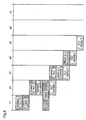
- Figure 12 is a chart diagram for explaining the conventional variable length coding method.
- ⁇ (white circle) means that data is determined, and numerals 01 to 09 denote process steps for respective coefficients. Further, Coding B corresponds to the first escape mode, Coding C corresponds to the second escape mode, and Coding D corresponds to the third escape mode.
- the process 01 is a process that is activated by Last, Run and Level (i.e., the fact that there are all data at the input/output time), and when a code corresponding to the combination of (Last, Run, Level) exists in a VLC table, Codel is outputted to the process 09, thereby completing the process.
- a code indicating "Not exist” is outputted to Coding B.
- the process 02 is a process that is activated by Last and Run in the case where the corresponding code does not exist in the VLC table in the process 01, and LMAX as the maximum Level value corresponding to the combination of (Last, Run) is outputted to process 03.
- the process 03 is a process that is activated by LMAX, and a process of subtracting LMAX from the Level value is carried out and a resulting NewLevel value to process 04 is outputted.
- the process 04 is a process that is activated by Last, Run and Newlevel, and when a code corresponding to the combination of (Last, Run, Newlevel) exists in a VLC table, a Code2 is outputted to the process 09, thereby completing the process. On the other hand, when the code corresponding to the combination of (Last, Run, Newlevel) does not exist in the VLC table, a code indicating "Not exist" is outputted to Coding C.
- the process 05 is a process that is activated by Last and Level in the case where the corresponding code does not exist in the VLC table in the process 04, and RMAX as the maximum Run value corresponding to the combination of (Last, Level) is outputted to the process 06.
- the process 06 is a process that is activated by RMAX, and a process of subtracting the sum of RMAX and 1 from the Run value is carried out and a resulting NewRun value is outputted to the process 07.
- the process 07 is a process that is activated by Last, NewRun and Level, and when a code corresponding to the combination of (Last, NewRun, Level) exists in a VLC table, a Code 3 is outputted to the process 09, thereby completing the process. On the other hand, when the code corresponding to the combination of (Last, NewRun, Level) does not exist in the VLC table, a code indicating "Not exist” is outputted to Coding D.
- the process 08 is a process of converting Las, Run and Level by FLC in the case where the corresponding code does not exist in the VLC table in the process 07, and a Code4 as a FLC is outputted to the process 09.
- an effective code is activated among the Code1-Code4 and the activated code is outputted.
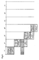
- Figure 13 is a diagram summarizing processing contents of each cycle of the prior art variable length coding method.
- the third cycle (3T) is a process that is activated by LMAX, in which VLC corresponding to the combination of Last, Run and NewLevel is carried out (LMAX VLC). Then, a judgement as to whether the result of the VLC corresponding to the combination of Last, Run and NewLevel exists in the table is made (LMAX VLC judgement).
- the fifth cycle (5T) is a process that is activating by RMAX, in which VLC corresponding to the combination of Last, NewRun and Level is carried out (RMAX VLC). Then, a judgement as to whether the result of the VLC corresponding to the combination of Last, NewRun and Level exists in the table is made (RMAX VLC judgement).
- the present invention is made to solve these problems, and has for its object to provide a variable length coding method and a variable length coding apparatus, which can reduces the number of arithmetic cycles and efficiently carries out VLC processes.
- a variable length coding method by which Run as preceding zero coefficients, Level as a value of a non-zero coefficient, and Last indicating whether the non-zero coefficient is the last one are taken from discrete cosine transform coefficients which are rearranged in an one-dimensional array as a combination of (Last, Run, Level), a VLC process of assigning a unique code to the combination is carried out, and when the VLC assignment cannot be performed, three escape modes are applied, thereby performing coding, in which processes of: step (a) of performing the code assignment for the combination of (Last, Run, Level); step (b), as a first escape mode, of subtracting LMAX as a maximum Level corresponding to (Last, Run) from Level, and performing code assignment for a combination including an obtained amended Level of (Last, Run, amended Level); step (c), as a second escape mode, of subtracting a value that is obtained by adding RMAX as a maximum Run corresponding
- the VLC process can be carried out in a reduced number of arithmetic cycles.
- the order of priorities by which coded data is selected in the step (e) is decided by selecting one of three patterns: (a), (b), (c), (d); (a), (c), (b), (d); and (a), (d).
- the priorities can be arbitrarily set, and further a unique code is always assigned by the FLC in step (d). Therefore, when the order of priorities are determined as step (a), step (d) (steps (b) and (c) are not in order), it can be forcefully decided not to select steps (b) and (c), whereby this method can conform to H.263 that is an image compression method by which the variable length coding is performed in steps (a) and (d).
- a variable length coding apparatus comprising an RMAX table for receiving a Level absolute value signal as an absolute value of a Level signal and a Last signal; an LMAX table for receiving a Run signal and the Last signal; a first VLC table for receiving the Level absolute value signal, a signal indicating the sign of the Level signal, the Run signal, and the Last signal; a first subtraction circuit for subtracting a sum of an output signal of the RMAX table and 1, from the Run signal; a second register for holding an output signal of the first subtraction circuit; a second VLC table for receiving an output signal of the second register, the Level absolute value signal, the signal indicating the sign of the Level signal, and the Last signal; a second subtraction circuit for subtracting an output signal of the LMAX table from the Level absolute value signal; a third register for holding an output signal of the second subtraction circuit; a third VLC table for receiving an output signal of the third register, the signal indicating the sign of the Level signal, the Run
- variable length coding apparatus that is constituted as described above, all processes can be implemented in two cycles, whereby the number of the process cycles can be reduced.
- the control circuit judges whether the output signal of the first register, the output signal of the fourth register, and the output signal of the fifth register are correct as VLC, and outputs the judgement result to the selection circuit according to preset priorities.
- the priorities can be arbitrarily set. Further, when the priorities are set so as to select the output signal of the first register and then the output signal of the FLC generation circuit (remaining two signals are not in order), this apparatus can conform to the image compression method according to H.263.
- a variable length coding apparatus comprising an RMAX table for receiving a Level absolute value signal as an absolute value of a Level signal and a Last signal; an LMAX table for receiving a Run signal and the Last signal; a first subtraction circuit for subtracting a sum of an output signal of the RMAX table and 1, from the Run signal; a second subtraction circuit for subtracting an output signal of the LMAX table from the Level absolute value signal; a second register for holding an output signal of the first subtraction circuit; a third register for holding an output signal of the second subtraction circuit; a first selection circuit for selecting one of an output signal of the third register and the Level absolute value signal; a second selection circuit for selecting one of an output signal of the second register and the Run signal; a VLC table for receiving an output signal of the first selection circuit, an output signal of the second selection circuit, a signal indicating the sign of the Level signal, and the Last signal; a first register for holding an output signal of the VLC table,
- the NewLevel signal and the NewRun signal can be calculated while simultaneously performing the normal VLC. Further, although the prior art VLC process requires six cycles, this apparatus can reduce the number of process cycles to five cycles. Furthermore, the process is conventionally carried out using three VLC tables, while this apparatus can perform the VLC with one VLC table, thereby reducing the circuit area.
- a variable length coding apparatus comprising an RMAX table for receiving a Level absolute value signal as an absolute value of a Level signal and a Last signal; an LMAX table for receiving a Run signal and the Last signal; a first subtraction circuit for subtracting a sum of an output signal of the RMAX table and 1, from the Run signal; a second subtraction circuit for subtracting an output signal of the LMAX table from the Level absolute value signal; a second register for holding an output signal of the first subtraction circuit; a third register for holding an output signal of the second subtraction circuit; a first selection circuit for selecting one of an output signal of the third register and the Level absolute value signal; a second selection circuit for selecting one of an output signal of the second register and the Run signal; a VLC table for receiving an output signal of the first selection circuit, and output signal of the second selection circuit, a signal indicating the sign of the Level signal, and the Last signal; a first register for holding an output signal of the VLC table;
- the NewLevel signal and the NewRun signal can be calculated while simultaneously performing the normal VLC.
- this apparatus can reduce the number of process cycles to four cycles.
- the process is conventionally carried out using three VLC tables, while this apparatus can perform the VLC with one VLC table, thereby reducing the circuit area.
- the control circuit judges whether the output signal of the first register is correct or not as VLC, further decides the number of cycles in which the output signal is incorrect, thereby performing control of the VLC, and changes an output order of the VLC according to predetermined priorities.
- variable length coding apparatus that is constituted as described above, the priorities can be arbitrarily set. Further, a unique code is always assigned in the FLC generation circuit. Therefore, when the priorities are set such that the output signal of the FLC generation circuit is selected when the normal VLC is judged and the result of the judgement is incorrect, this apparatus can conform to the image compression method according to H.263.
- a variable length coding apparatus comprising a first selection circuit for receiving a Level absolute value signal as an absolute value of a Level signal, a Last signal, and fixed values, selecting one of the Level absolute value signal and the fixed value to output a first output signal, and selecting one of the Last signal and the fixed value to output a second output signal; an RMAX table for receiving the first output signal and the second output signal; a second selection circuit for receiving a Run signal, the Last signal and fixed values, selecting one of the Run signal and the fixed value to output a third output signal, and selecting one of the Last signal and the fixed value to output a fourth selection signal; an LMAX table for receiving the third output signal and the fourth output signal; a first subtraction circuit for subtracting a sum of an output signal of the RMAX table and 1, from the Run signal; a second subtraction circuit for subtracting an output signal of the LMAX table from the Level absolute value signal; a second register for holding an output signal of the first subtraction circuit;
- variable length coding apparatus that is constituted as described above, the RMAX table is never accessed in the first cycle, whereby the consumed power can be reduced. Further, while the prior art VLC process requires six cycles, the number of process cycles can be reduced to four cycles. Furthermore, the processes are conventionally performed using three VLC tables, while the VLC process can be carried out with one VLC table, whereby the circuit area can be reduced.
- the control circuit judges whether the output signal of the first register is correct or not as VLC and further decides the number of cycles in which the output signal is incorrect, thereby performing control of the VLC, and changes an output order of the VLC according to predetermined priorities.
- variable length coding apparatus that is constituted as described above, the priorities can be arbitrarily set. Further, a unique code is always assigned in the FLC generation circuit. Therefore, when the priorities are set such that the output signal of the FLC generation circuit is selected when the normal VLC is judged and the result of the judgement is incorrect, this apparatus can conform to the image compression method according to H.263.
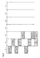
- Figure 1 is a chart diagram for explaining a variable length coding method according to a first embodiment of the present invention.
- Figure 2 is a diagram for explaining combinations of priorities of outputting codes according to the first embodiment.
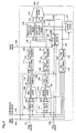
- Figure 3 is a block diagram for explaining a structure of a variable length coding apparatus according to a second embodiment of the present invention.
- Figures 4 are timing charts for explaining operations of a control circuit according to the second embodiment of the present invention.
- Figure 5 is a diagram summarizing contents of a process of each cycle according to the second embodiment.
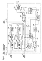
- Figure 6 is a block diagram for explaining a structure of a variable length coding apparatus according to a third embodiment of the present invention.
- Figures 7 are timing charts for explaining operations of a control circuit according to the third embodiment.
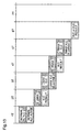
- Figure 8 is a diagram summarizing contents of a process of each cycle when a process is carried out in 5T according to the third embodiment.
- Figure 9 is a diagram summarizing contents of a process of each cycle when processes are carried out in 4T according to the third embodiment.
- Figure 10 is a block diagram for explaining a structure of a variable length coding apparatus according to a fourth embodiment of the present invention.
- Figure 11 is a diagram summarizing contents of processes of each cycle according to the fourth embodiment.
- Figure 12 is a chart diagram for explaining a prior art variable length coding method.
- Figure 13 is a diagram summarizing contents of processes of each cycle according to the prior art variable length coding method.
- variable length coding method among DCT coefficients rearranged in an one-dimensional array, taking Run as the number of preceding zero coefficients, Level as a value of a non-zero coefficient and Last indicating whether the non-zero coefficient is the last one as a combination of (Last, Run, Level), a Variable Length Code (hereinafter, abbreviated as VLC) assignment of assigning a unique code to this combination is performed, and when the VLC assignment cannot be performed, three escape modes (which will be described later) are applied thereto.
- VLC Variable Length Code
- Figure 1 is a chart diagram for explaining a variable length coding method according to the first embodiment.
- ⁇ (white circle) represents that data is determined
- P1-P9 denote process steps for respective coefficients.
- Coding 2 corresponds to the first escape mode
- Coding 3 corresponds to the second escape mode
- Coding 4 corresponds to the third escape mode.
- the process P1 is a process that is activated by Last, Run and Level (i.e., the fact that there are all data at the input/output time), in which when a code corresponding to the combination of (Last, Run, Level) exists in a VLC table, a Code A of normal VLC is outputted to the process P9.
- Last, Run and Level i.e., the fact that there are all data at the input/output time
- the process P2 is a process that is activated by Last and Run, in which LMAX as the maximum Level value corresponding to the combination of (Last, Run) is outputted to the process P3.
- the process P3 is a process activated by LMAX, in which a process of subtracting LMAX from the Level value is carried out and a resulting NewLevel value is outputted to the process P4.
- the process P4 is a process that is activated by Last, Run and NewLevel, in which when a code corresponding to the combination of (Last, Run, NewLevel) exists in a VLC table, a Code B is outputted to the process P9.
- the Code B is "0000011” (code of the ESC (escape) code), "0" (indicating VLC of LMAX) and the VLC result, which are outputted as coded LMAX data to the process P9.
- a code indicating "Not exist” is outputted to the process P9.
- the process P5 is a process that is activated by Last and Level, in which an RMAX value as the maximum Run corresponding to the combination of (Last, Level) is outputted to the process P6.
- the process P6 is a process activated by RMAX, in which a process of subtracting the sum of RMAX and 1 from the Run value is carried out, and a resulting NewRun value is outputted to the process P7.
- the process P7 is a process that is activated by Last, NewRun and Level, in which when a code corresponding to the combination of (Last, NewRun, Level) exists in the VLC table, a code C is outputted to the process P9.
- the Code C is "0000011” (ESC code), "10” (indicating VLC of RMAX) and the VLC result, which are outputted to the process P9 as coded RMAX data.
- ESC code ESC code
- 10 indicating VLC of RMAX
- VLC result which are outputted to the process P9 as coded RMAX data.
- a code indicating "Not.exist” is outputted to the process P9.
- the process P8 is a process of converting data into a FLC (Fixed Length Code), in which in the case of H.263, "0000011” (ESC code) and the FLC result, i.e., (Last-1 bits, Run-6 bits, Level-8 bits) are outputted to the process P9 as FLC coded data.
- FLC Fixed Length Code
- ESC code ESC code
- 11 indicating a FLC according to MPEG4
- a FLC result i.e., (Last-1 bits, Run-6 bits, 1, Leve-12 bits, 1) are outputted to the process P9 as FLC coded data.
- a ⁇ D denote Code A ⁇ Code D, respectively.
- priority 1 is set as the combination of priorities in the process P9.
- the data of Code A exists in the process P9
- the data of Code A is outputted in the process P9 even when any data of Code B, Code C and Code D exist.
- the data of Code B is outputted in the process P9 even when any data of Code C and Code D exists.
- the data of Code A and Code B do not exist but data of Code C exists in the process P9
- the data of Code C is outputted in the process P9 even when data of Code D exists.
- the data of Code D is outputted in the process P9.
- the respective processes of Coding 1 (P1), Coding 2 (P2, P3, P4), Coding 3 (P5, P6, P7), and Coding 4 (P8) are carried out simultaneously, and data are outputted according to the predetermined priority. Therefore, all processes can be carried out in two steps (processing and judgement of each coding), whereby the number of process steps can be reduced. Further, assuming that the number of process steps of P2, P3 and P4 is two steps and the number of process steps of P5, P6 and P7 is two steps, all of the processes can be carried out in three steps.
- variable length coding apparatus is an apparatus for realizing the above-mentioned variable length coding method of the first embodiment.
- Figure 3 is a block diagram for explaining a structure of the variable length coding apparatus according to the second embodiment.
- numeral 100 denotes a Level signal
- numeral 101 denotes a Last signal
- numeral 102 denotes a Run signal
- numeral 103 denotes a Sign signal indicating the sign of the Level signal 100
- numeral 104 denotes a Level absolute value signal as the absolute value of the Level signal 100.
- Numeral 105 denotes a FLC generation circuit.
- Numeral 106 denotes a FLC data signal as an output signal of the FLC generation circuit 105.
- Numeral 107 denotes an RMAX table.
- Numeral 108 denotes an RMAX data signal as an output signal of the RMAX table 107.
- Numeral 109 denotes a first subtraction circuit.
- Numeral 110 denotes an output signal of the first subtraction circuit 109.
- Numeral 115 denotes a second register for holding the output signal 110 of the first subtraction circuit 109.
- Numeral 182 denotes a NewRun signal outputted from the second register 115.
- Numeral 111 denotes a second VLC table.
- Numeral 114 denotes a second VLC data signal as an output signal of the second VLC table 111.
- Numeral 180 denotes a fourth register for holding the second VLC data signal 114.
- Numeral 116 denotes a VLC data signal generated using the NewRun signal 182.
- Numeral 117 denotes an LMAX table.
- Numeral 118 denotes an LMAX data signal as an output signal of the LMAX table 117.
- Numeral 119 denotes a second subtraction circuit.
- Numeral 120 denotes an output signal of the second subtraction circuit 119.
- Numeral 122 denotes a third register for holding an output signal of the second subtraction circuit 119.
- Numeral 183 denotes a NewLevel signal outputted by the third register 122.
- Numeral 112 denotes a third VLC table.
- Numeral 121 denotes a third VLC data signal as an output signal of the third VLC table 112.
- Numeral 181 denotes a fifth register for holding the third VLC data signal 121.
- Numeral 123 denotes a VLC data signal generated using the NewLevel signal 183.
- Numeral 113 denotes the first VLC table.
- Numeral 124 denotes a first VLC data signal as an output signal of the first VLC table 113.
- Numeral 125 denotes a first register for holding the first VLC data signal 124.
- Numeral 126 denotes a normal VLC data signal.
- Numeral 170 denotes an RMAX VLC generation circuit for receiving the VLC data signal 116 generated using the NewRun signal and generating coded data of RMAX.
- Numeral 175 denotes an RMAX data signal as an output signal of the VLC generation circuit 170.
- Numeral 171 denotes an LMAX VLC generation circuit for receiving the VLC data signal 123 generated using the NewLevel signal and generating coded data of LMAX.
- Numeral 176 denotes an LMAX data signal as an output signal of the LMAX VLC generation circuit 171.
- Numeral 127 denotes a control circuit for receiving the normal VLC data signal 126, the VLC data signal 116 generated using the NewRun signal and the VLC data signal 123 generated using the NewLevel signal, and selecting a VLC data signal according to the preset priorities.
- Numeral 128 denotes a selection signal for outputting the data signal selected by the control circuit 127.
- Numeral 129 denotes a selection circuit for receiving the RMAX data signal 175, the LMAX data signal 176, the FLC data signal 106 and the normal VLC data signal 126, and selecting a data signal to be outputted in accordance with the selection signal 128.
- Numeral 130 denotes the data signal selected by the selection circuit 129.
- variable length coding apparatus Next, the operation of the variable length coding apparatus according to the second embodiment will be described with making the above-mentioned block diagram of figure 3 correspond to the chart diagram of figure 1.
- the first VLC table 113 receives the Last signal 101, the Run signal 102, the Level absolute value 104 and the Sign signal 103, thereby generating the first VLC data signal 124 (P1), and stores the generated signal 124 in the first register 125. Then, the first register 125 outputs the normal VLC data signal 126 to the control circuit 127 and the selection circuit 129 (P9).
- the RMAX.table 107 receives the Last signal 101 and the Level absolute value signal 104, thereby generating the RMAX data signal 108 (P5), and outputs the generated signal 108 to the first subtraction circuit 109.
- the first subtraction circuit 109 receives the RMAX data signal 108 and the Run signal 102, subtracts the sum of the RMAX data signal 108 and 1 from the Run signal 102 value (P6), and outputs the obtained result to the second register 115 as the output signal 110 of the first subtraction circuit.
- the second register 115 holds the output signal 110 inputted by the first subtraction circuit.
- the second VLC table 111 receives the NewRun signal 182 outputted from the second register 115, the Last signal 101, the Level absolute value signal 104 and the Sign signal 103, thereby generating the second VLC data signal 114 (P7), and outputs the generated signal 114 to the fourth register 180.
- the fourth register 180 holds the inputted second VLC data signal 114.
- the fourth register 180 outputs the VLC data signal 116, which is generated using the NewRun signal, to the control circuit 127.
- the LMAX table 117 receives the Last signal 101 and the Run signal 102, thereby generating the LMAX data signal 118 (P2), and outputs the generated signal 118 to the second subtraction circuit 119.
- the second subtraction circuit 119 receives the LMAX data signal 118 and the Level absolute value signal 104, thereby subtracting the LMAX data signal 118 from the Level absolute value signal 104 (P3), and outputs the obtained result to the third register 122 as the output signal 120 of the second subtraction circuit.
- the third register 122 holds the output signal 120 inputted from the second subtraction circuit.
- the third VLC table 112 receives the NewLevel signal 183 outputted from the third register 122, the Last signal 101, the Run signal 102 and the Sign signal 103, thereby generating the third VLC data signal 121 (P4), and outputs the generated signal 121 to the fifth register 181.
- the fifth register 181 holds the inputted third VLC data signal 121.
- the fifth register 181 outputs the VLC data signal 123, which is generated using the NewLevel signal, to the control circuit 127.
- the RMAX VLC generation circuit 170 performs VLC assignment to the VLC data signal 116 generated using the NewRun signal, which is outputted from the fourth register 180, and outputs (ESC code + "0" + VLC result) as the RMAX data signal 175 that is coded RMAX data, to the selection circuit 129 (P9). Further, the LMAX VLC generation circuit 171 performs VLC assignment to the VLC data signal 123 generated using the NewLevel signal, which is outputted from the fifth register 181, and outputs (ESC code + "10" + VLC result) as the LMAX data signal 176 that is coded LMAX data, to the selection circuit 129 (P6).
- the control circuit 127 receives the normal VLC data signal 126 outputted from the first register 125, the VLC data signal 116 generated using the NewRun signal, which is outputted from the fourth register 180, and the VLC data signal 123 generated using the NewLevel signal, which is outputted from the fifth register 181, and makes a judgement as to whether each of the VLC data signals is correct as VLC. Then, the control circuit 127 outputs the selection signal 128 for selecting the VLC data signal according to preset priorities.
- the priorities are set to select data in the order of: normal VLC data, VLC data generated using the NewLevel signal, VLC data generated using the NewRun signal, and FLC data (Priority 1 in figure 2).
- the control circuit 127 when the normal VLC data 126 exists in the control circuit 127, the control circuit 127 outputs the selection signal 128 for selecting the normal VLC data signal 124 to the selection circuit 129, regardless of existence of the VLC data signal 123 generated using the NewLevel signal or the VLC data signal 116 generated using the NewRun signal.
- the control circuit 127 when the normal VLC data signal 126 does not exist but the VLC data signal 123 generated using the NewLevel signal exists in the control circuit 127, the control circuit 127 outputs the selection signal 128 for selecting the VLC data signal 123 generated using the NewLevel signal to the selection circuit 129, regardless of existence of the VLC data signal 116 generated using the NewRun signal. Further, when the normal VLC data signal 129 and the VLC data signal 123 generated using the NewLevel signal do not exist but the VLC data signal 116 generated using the NewRun signal exists in the control circuit 127, the control circuit 127 outputs the selection signal 128 for selecting the VLC data signal 116 generated using the NewRun signal to the selection circuit 129.
- the selection circuit 129 selects one of the VLC data signals under the control of the selection signal 128 inputted from the control circuit 127, and outputs the selected VLC data signal as the data signal 130.
- the selection circuit 129 selects the FLC data signal 106 and outputs the signal as the data signal 130.
- Figures 4 are timing charts for explaining the operation of the control circuit according to the second embodiment.
- clock is a signal of a prescribed cycle
- tcoef_e is a start signal indicating that there are all data enabling to start VLC
- MPEG4/H.263 is a signal indicating one of the standards, and this signal indicates MPEG4 when it is H (High) while indicating H.263 when it is L (Low).
- Counter denotes the start of a judgement and the number of times of the judgement.
- Dec_nomal is the normal VLC data.
- signal 126 which indicates the result of the first VLC table 113.
- Dec_lmax is a VLC data signal 123 generated using the NewLevel signal, which indicates the result of the third VLC table 112.
- Dec_rmax is the VLC data signal 116 generated using the NewRun signal, which indicates the result of the second VLC table 111.
- "Sel_nomal” is changed to H when the result of the normal VLC data signal 126 (dec_nomal) exists in the VLC table.
- “Sel_lmax” is changed to H when the result of the VLC data signal 123 (dec_lmax) that is generated using the NewLevel signal exists in the VLC table.
- “Sel_rmax” is changed to H when the result of the VLC data signal 116 (dec_rmax) that is generated using the NewRun signal exists in the VLC table.
- Figure 4(a) is a timing chart in a case of selecting the normal VLC data signal according to MPEG4.
- Figure 4(b) is a timing chart in a case of selecting the VLC data signal generated using the NewLevel signal according to MPEG4.
- Figure 4(c) is a timing chart in a case of selecting a VLC data signal generated using the NewRun signal according to MPEG4.
- Figure 4(e) is a timing chart in a case of selecting the normal VLC data signal according to H.263.
- Figure 4(f) is a timing chart in a case of selecting the FLC data signal according to H.263.
- variable length coding apparatus of the second embodiment the processes for the normal VLC data, the VLC data generated using the NewLevel signal and the VLC data generated using the NewRun signal are carried out simultaneously, and the results are outputted according to the preset priorities. Therefore, all the processes can be carried out in three cycles, thereby greatly reducing the number of process cycles.
- the signals are selected in the order of: normal VLC data, VLC data generated using the NewLevel signal, VLC data generated using the NewRun signal, and FLC data.
- the order of the signal selection is not limited to this order, and the priorities may be set such that the signals are selected in the order of: normal VLC data, VLC data generated using the NewRun signal, VLC data generated using the NewLevel signal, and FLC data.
- the priorities are set such that the signals are selected in the order of: normal VLC data and then FLC data, it is possible to carry out the VLC process without selecting VLC data generated using the NewLevel signal or VLC data generated using the NewRun signal.
- priorities can also conform to the VLC process of H.263. Further, the priorities of the VLC data generated using the NewLevel signal and the VLC data generated using the NewRun signal can be arbitrarily varied with image data. Thereby, a variable length coding apparatus which reduces the number of cycles in the escape mode can be obtained.
- variable length coding apparatus performs VLC using one VLC table.
- Figure 6 is a block diagram for explaining a structure of a variable length coding apparatus of the third embodiment.
- Numeral 135 denotes an output signal of the first subtraction circuit 109.
- Numeral 136 denotes a second register for holding the output signal 135 of the first subtraction circuit.
- Numeral 137 denotes a NewRun signal outputted from the second register 136.
- Numeral 138 denotes an output signal of the second subtraction circuit 119.
- Numeral 139 denotes a third register for holding the output signal 138 of the second subtraction circuit 119.
- Numeral 140 denotes a NewLevel signal outputted from the third register 139.
- Numeral 141 denotes a first selection circuit for selecting one of the Level absolute value signal 104 and the NewLevel signal 140.
- Numeral 142 denotes an output signal of the first selection circuit 141.
- Numeral 143 denotes a second selection circuit for selecting one of the Run signal 102 and the NewRun signal 137.
- Numeral 144 denotes an output signal of the second selection circuit 143.
- Numeral 131 denotes a VLC table for receiving the Last signal 101, the Sign signal 103, the output signal 142 of the first selection circuit and the output signal 144 of the second selection circuit.
- Numeral 132 denotes a VLC table output signal outputted from the VLC table 131.
- Numeral 133 denotes a first register for holding the VLC table output signal 132.
- Numeral 134 denotes a VLC data signal as an output signal of the first register 133.
- Numeral 145 denotes a control circuit for receiving the VLC data signal 134.
- Numeral 146 denotes a first selection signal that controls the first selection circuit 141 for selecting one of the Level absolute value signal 104 and the NewLevel signal 140.
- Numeral 147 denotes a second selection signal that controls the second selection circuit 143 for selecting one of the Run signal 102 and the NewRun signal 137.
- Numeral 148 denotes a third selection signal for outputting the VLC data signal 134 selected by the control circuit 145 to the VLC generation circuit 172 and the third selection circuit 149.
- Numeral 172 denotes a VLC generation circuit for receiving the third selection signal 148 and the VLC data signal 134 and generating coded data.
- Numeral 177 denotes a generated VLC signal as an output signal of the VLC generation circuit 172.
- Numeral 149 denotes a third selection circuit for selecting one of the generated VLC signal 177 and the FLC data signal 106
- variable length coding apparatus Next, the operation of the variable length coding apparatus according to the third embodiment will be described with reference to figure 6.
- the control circuit 145 controls the first selection circuit 141 by means of the first selection signal 146, and controls the second selection circuit 143 by means of the second selection signal 147. Then, the first selection circuit 141 selects the Level absolute value signal 104 under the control of the first selection signal 146, and outputs the signal 104 to the VLC table 131 as the output signal 142 of the first selection circuit 141. Further, the second selection circuit 143 selects the Run signal 102 under the control of the second selection signal 147, and outputs the signal 102 to the VLC table 131 as the output signal 144 of the second selection circuit 143.
- the VLC table 131 receives the output signal 142 of the first selection circuit as the Last signal 101, the Sign signal 103 and the Level absolute value signal 104, and the output signal 144 of the second selection circuit as the Run signal 102, performs normal VLC, thereby generating the VLC table output signal 132, and outputs the signal 132 to the first register 133.
- the first register 133 holds the VLC table output signal 132, and outputs the VLC data signal 134, which is a normal VLC, to the control circuit 145 and the VLC generation circuit 172.
- the control circuit 145 receives the VLC data signal 134 as the normal VLC data, and makes a judgement as to whether the VLC data signal is correct in a VLC table. As a result of the judgement, when the VLC data signal 134 is a correct VLC, the control circuit 145 outputs the third selection signal 148 for selecting the VLC data signal 134 to the VLC generation circuit 172 and the third selection circuit 149.
- the VLC generation circuit 172 outputs the selected VLC data signal 134 to the third selection circuit 149 as the generated VLC signal 177, taking the VLC data signal 134 as normal VLC data.
- the third selection circuit 149 selects the generated VLC signal 177 under the control of the third selection signal 148, and outputs the signal 177 as the data signal 130.
- the LMAX table 117 receives the Last signal 101 and the Run signal 102, generates the LMAX data signal 118, and outputs the LMAX data signal to the second subtraction circuit 119.
- the second subtraction circuit 119 receives the LMAX data signal 118 and the Level absolute value signal 104, subtracts the LMAX data signal 118 from the Level absolute value signal 104, and outputs the obtained result to the third register 139 as the output signal 138 of the second subtraction circuit.
- the third register 139 holds the output signal 138 of the second subtraction circuit, and outputs the signal to the first selection circuit 141 as the NewLevel signal 140.
- the control circuit 145 controls the first selection circuit 141 by means of the first selection signal 146, and the first selection circuit 141 selects the NewLevel signal 140 and outputs the signal 140 to the VLC table 131 as the output signal 142 of the first selection circuit. Further, the control circuit 145 controls the second selection circuit 143 by means of the second selection signal 147, and the second selection circuit 143 selects the Run signal 102 and outputs the signal 102 to the VLC table 131 as the output signal 144 of the second selection circuit.
- the VLC table 131 receives the output signal 142 of the first selection circuit as the Last signal 101, the Sign signal 103 and the NewLevel signal 140, and the output signal 144 of the second selection circuit as the Run signal 102, performs LMAX VLC, thereby generating the VLC table output signal 132, and outputs the signal 132 to the first register 133.
- the first register 133 holds the VLC table output signal 132 as an LMAX VLC.
- the control circuit 145 receives the VLC data signal 134 as the LMAX VLC, and makes a judgement as to whether the signal is a correct VLC. As a result of the judgement, when the VLC data signal 134 is a correct VLC, the control circuit 145 outputs the third selection signal 148 for selecting the VLC data signal 134, to the VLC generation circuit 172 and the third selection circuit 149.
- the VLC generation circuit 172 performs coding by adding an ESC code and a code indicating the LMAX VLC, and outputs the obtained result to the third selection circuit 149 as the generated VLC signal 177.
- the third selection circuit 149 selects the generated VLC signal 177 under the control of the third selection signal 148, and outputs the signal 177 as the data signal 130.
- the RMAX table 107 receives the Last signal 101 and the Level absolute value signal 104, generates an RMAX data signal 108, and outputs the RMAX data signal 108 to the first subtraction circuit 109.
- the first subtraction circuit 109 receives the RMAX data signal 108 and the Run signal 102, subtracts the sum of the RMAX data signal 108 and 1 from the Run signal 102, and outputs the obtained result to the second register 136 as the output signal 135 of the first subtraction circuit 109.
- the second register 136 holds the output signal 135 of the first subtraction circuit, and outputs the signal to the second selection circuit 143 as the NewRun signal 137.
- the control circuit 145 controls the first selection circuit 141 by means of the first selection signal 146, and the first selection circuit 141 selects the Level absolute value signal 104 and outputs the signal to the VLC table 131 as the output signal 142 of the first selection circuit 141. Further, the control circuit 145 controls the second selection circuit 143 by means of the second selection signal 147, and the second selection circuit 143 selects the NewRun signal 137 and outputs the signal to the VLC table 131 as the output signal 144 of the second selection circuit.
- the VLC table 131 receives the output signal 142 of the first selection circuit as the Last signal 101, the Sign signal 103 and the Level absolute value signal 104, and the output signal 144 of the second selection circuit as the NewRun signal 137, performs RMAX VLC, thereby generating a VLC table output signal 132, and outputs the VLC table output signal 132 to the first register 133.
- the first register 133 holds the VLC table output signal 132 as an RMAX VLC.
- the control circuit 145 receives the VLC data signal 134 as an RMAX VLC, and makes a judgement as to whether the signal is a correct VLC. As a result of the judgement, when the VLC data signal 134 is a correct VLC, the control circuit 145 outputs the third selection signal 148 for selecting the VLC data signal 134, to the VLC generation circuit 172 and the third selection circuit 149.
- the VLC generation circuit 172 performs coding by adding an ESC code and a code indicating an RMAX VLC, and outputs the obtained result to the third selection circuit 149 as the generated VLC signal 177.
- the third selection circuit 149 selects the generated VLC signal 177 under the control of the third selection signal 148, and outputs the signal 177 as the data signal 130.
- the third selection circuit 149 selects the FLC data signal 106 and outputs the signal as the data signal 130.
- figures 7 are timing charts for explaining an operation of the control circuit according to the third embodiment of the present invention.
- Figure 7(a) is a timing chart in a case of selecting a normal VLC data signal according to MPEG4.
- Figure 7(b) is a timing chart in a case of selecting a VLC data signal generated using a NewLevel signal according to MPEG4.
- control circuit 145 outputs the third selection signal 148 for selecting the VLC data signal 134 that is generated using the NewLevel signal, and the third selection circuit 149 selects the generated VLC signal 177 as the VLC data signal generated using the NewLevel signal, under the control of the third selection signal 148.
- Figure 7(c) is a timing chart in a case of selecting a VLC data signal that is generated using a NewRun signal according to MPEG4.
- control circuit 145 outputs the third selection signal 148 for selecting a VLC data signal that is generated using a NewRun signal, and the third selection circuit 149 selects the generated VLC signal 177 as the VLC data signal generated using the NewRun signal, under the control of the third selection signal 148.
- Figure 7(d) is a timing chart in a case of selecting a FLC data signal according to MPEG4.
- Figure 7(e) is a timing chart in a case of selecting a normal VLC data signal according to H.263.
- Figure 7(f) is a timing chart in a case of selecting a FLC data signal according to H.263.
- Figure 8 is a diagram summarizing the process contents of each cycle according to the third embodiment.
- the RMAX VLC judgement is made in the fourth cycle, and when the RMAX VLC result does not exists in the control circuit 145 the FLC data is outputted in the fifth cycle.
- a diagram which summarizes process contents of each cycle in a case of performing the operations in figure 8 in the fourth cycle is shown in figure 9.
- figure 9 The difference of figure 9 from figure 8 is that when the process of the fourth cycle (4T) is started the RMAX VLC judgement is made, and when the RMAX VLC result exists in the control circuit 145 this result is outputted, while when the RMAX VLC result does not exist in the control circuit 145 the FLC data is outputted in the same cycle, thereby finishing the processes.
- the normal VLC is performed while simultaneously an LMAX VLC and an RMAX VLC are generated, and when the VLC data signal is judged to be correct, the judgement of the LMAX VLC and RMAX VLC is not made. Therefore, it is possible to calculate the NewLevel signal and the NewRun signal while performing the normal VLC.
- the VLC process conventionally requires six cycles, while according to the third embodiment the number of process cycles can be reduced to four cycles or five cycles. Further, in the prior art, the processes are carried out using three VLC tables, while according to the third embodiment the VLC can be performed using one VLC table, whereby the circuit area can be reduced.
- the signals are selected in the order of: normal VLC data, VLC data generated using a NewLevel signal, VLC data generated using a NewRun signal, FLC data.
- the order in which the signals are selected is not limited this order.
- the priorities may be decided such that the signals are selected in the following order of: normal VLC data, VLC data generated using a NewRun signal, VLC data generated using a NewLevel signal, FLC data.
- the VLC process can be carried out without selecting VLC data generated using the NewLevel signal or the VLC data generated using the NewRun signal.
- priorities can also conform to the VLC process according to H.263. Further, the priorities of the VLC data generated using the NewLevel signal and the VLC data generated using the NewRun signal can be arbitrarily varied with image data. Thereby, a variable length coding apparatus which reduces the number of cycles in the escape mode can be obtained.
- the counter is controlled for counting the number of incorrect VLC codes, whereby the priorities can be arbitrarily set.
- the counter outputs VLC data in the order of: normal VLC data, VLC data generated using the NewLevel signal, VLC data generated using the NewRun signal, and FLC data, while the counter can be controlled to set the order of priorities as normal VLC data, VLC data generated using the NewRun signal, VLC data generated using the NewLevel signal, and FLC data. Even when the setting is changed to such order, the same effects as those described above can be obtained. Further, when the priorities are set in the order of: normal VLC data, FLC data, the processes conforming to H.263 can be carried out.
- variable length coding apparatus performs VLC using one VLC table as well as does not access needless processes.
- Figure 10 is a block diagram for explaining a structure of the variable length coding apparatus according to the fourth embodiment.
- Numeral 150 denotes a third selection circuit for selecting one of the Level absolute value signal 104 and the NewLevel signal 140.
- Numeral 151 denotes an output signal of the third selection circuit 150.
- Numeral 152 denotes a fourth selection circuit for selecting one of the Run signal 102 and the NewRun signal 137.
- Numeral 153 denotes an output signal of the fourth selection circuit 152.
- Numeral 154 denotes a control circuit for receiving the VLC data signal 134.
- Numeral 157 denotes a third selection signal that controls the third selection circuit 150, thereby selecting one of the Level absolute value signal 104 and the NewLevel signal 140.
- Numeral 158 denotes a fourth selection signal that controls the fourth selection circuit 152, thereby selecting one of the Run signal 102 and the NewRun signal 137.
- Numeral 159 denotes a first selection circuit for receiving the Level absolute value signal 104, the Last signal 101 and fixed values.
- Numeral 160 denotes a first output signal which is the Level absolute value signal 104 or the fixed value outputted from the first selection circuit 159.
- Numeral 161 denotes a second output signal which is the Last signal 101 or the fixed value outputted from the first selection circuit 159.
- Numeral 162 denotes a second selection circuit for receiving the Run signal 102, the Last signal 101 and fixed values.
- Numeral 163 denotes a third output signal which is the Run signal 102 or the fixed value outputted from the second selection circuit 162.
- Numeral 164 denotes a fourth output signal which is the Last signal 101 or the fixed value outputted from the second selection circuit 162.
- Numeral 155 denotes a first selection signal for controlling the first selection circuit 159, thereby selecting a signal that is to be outputted from the Level absolute value signal 104, the Last signal 101 and the fixed values.
- Numeral 156 denotes a second selection signal for controlling the second selection circuit 162, thereby selecting a signal that is to be outputted from the Run signal 102, the Last signal 101 and the fixed values.
- Numeral 165 denotes a fifth selection signal for outputting the VLC data signal 134 selected by the control circuit 154 to the VLC generation circuit 172 and the fifth selection circuit 166.
- Numeral 166 denotes a fifth selection circuit for selecting one of the generated VLC signal 177 and the FLC data signal 106.
- variable length coding apparatus Next, the operation of the variable length coding apparatus according to the fourth embodiment will be described with reference to figure 10.
- the control circuit 154 controls the third selection circuit 150 by means of the third selection signal 157, and the fourth selection circuit 152 by means of the fourth selection signal 158. Then, the third selection circuit 150 selects the Level absolute value signal 104 under the control of the third selection signal 157, and outputs the selected signal to the VLC table 131 as the output signal 151 of the third selection circuit.
- the fourth selection circuit 152 is controlled by the fourth selection signal 158, thereby selecting the Run signal 102, and outputs the selected signal to the VLC table 131 as the output signal 153 of the fourth selection circuit.
- the VLC table 131 receives the Last signal 101, the Sign signal 103, the output signal 151 of the third selection circuit as the Level absolute value signal 104, and the output signal 153 of the fourth selection circuit as the Run signal 102, then performs normal VLC, thereby generating the VLC table output signal 132, and outputs the generated signal 132 to the first register 133.
- the first register 133 holds the VLC table output signal 132, and outputs the VLC data signal 134 as the normal VLC to the control circuit 154 and the VLC generation circuit 172.
- the control circuit 154 receives the VLC data signal 134 as the normal VLC data, and makes a judgement as to whether this signal is correct or not in the VLC table. As a result of the judgement, when the VLC data signal 134 is a correct VLC, the control circuit 154 outputs the fifth selection signal 165 for selecting the VLC data signal 134, to the VLC generation circuit 172 and the fifth selection circuit 166.
- the VLC generation circuit 172 outputs the selected VLC data signal 134 to the fifth selection circuit 166 as a generated VLC signal 177, with taking the VLC data signal 134 as normal VLC data.
- the fifth selection circuit 166 selects the generated VLC signal 177 under the control of the fifth selection signal 165, and outputs the selected signal 177 as the data signal 130.
- control circuit 154 controls the second selection circuit 162 by means of the second selection signal 156.
- the second selection circuit 162 selects the Run signal 102 and the Last signal 101 under the control of the second selection signal 156, and outputs the selected signals to the LMAX table 117 as the third output signal 163 and the fourth output signal 164, respectively.
- the LMAX table 117 receives the third output signal 163 and the fourth output signal 164, generates an LMAX data signal 118, and outputs the generated signal 118 to the second subtraction circuit 119.
- the second subtraction circuit 119 receives the LMAX data signal 118 and the Level absolute value signal 104, subtracts the LMAX data signal 118 from the Level absolute value 104, and outputs the obtained result to the third register 139 as the output signal 138 of the second subtraction circuit.
- the third register 139 holds the output signal 138 of the second subtraction circuit, and outputs the signal to the third selection circuit 150 as a NewLevel signal 140.
- the control circuit 154 controls the third selection circuit 150 by means of the third selection signal 157, and controls the fourth selection circuit 152 by means of the fourth selection signal 158.
- the third selection circuit 150 selects the NewLevel signal 140 under the control of the third selection signal 157, and outputs the signal to the VLC table 131 as the output signal 151 of the third selection circuit.
- the fourth selection circuit 152 selects the Run signal 102 under the control of the fourth selection signal 158, and outputs the signal to the VLC table 131 as the output signal 153 of the fourth selection circuit.
- the VLC table 131 receives the Last signal 101, the Sing signal 103, the output signal 151 of the third selection circuit as the NewLevel signal 140 and the output signal 153 of the fourth selection circuit as the Run signal 102, performs LMAX VLC, thereby generating a VLC table output signal 132, and outputs the signal 132 to the first register 133.
- the first register 133 holds the VLC table output signal 132 as an LMAX VLC.
- the control circuit 154 receives the VLC data signal 134 as LMAX data, and makes a judgement as to whether the signal is a correct VLC. As a result of the judgement, when the VLC data signal 134 is a correct VLC, the control circuit 154 outputs the fifth selection signal 165 for selecting the VLC data signal 134, to the VLC generation circuit 172 and the fifth selection circuit 166.
- the VLC generation circuit 172 adds an ESC code and a code indicating the VLC of LMAX, to perform coding, and outputs a generated VLC signal 177 to the fifth selection circuit 166.
- the fifth selection circuit 166 selects the generated VLC signal 177 under the control of the fifth selection signal 165, and outputs the selected signal as the data signal 130.
- control circuit 154 controls the first selection circuit 159 by means of the first selection signal 155.
- the first selection circuit 159 selects the Level absolute value signal 104 and the Last signal 101 under the control of the first selection signal 155, and outputs the selected signals to the RMAX table 107 as the first output signal 160 and the second output signal 161, respectively.
- the RMAX table 107 receives the first output signal 160 and the second output signal 161, generates an RMAX data signal 108, and outputs the signal 108 to the first subtraction circuit 109.
- the first subtraction circuit 109 receives the RMAX data signal 108 and the Run signal 102, subtracts the sum of the RMAX data signal 108 and 1, from the value of the Run signal 102, and outputs the obtained result to the second register 136 as the output signal 135 of the first subtraction circuit.
- the second register 136 holds the output signal 135 of the first subtraction circuit, and outputs the signal to the fourth selection circuit 152 as a NewRun signal 137.
- the control circuit 154 controls the third selection circuit 150 by means of the third selection signal 157 and the fourth selection circuit 152 by means of the fourth selection signal 158.
- the third selection circuit 150 selects the Level absolute value signal 104 under the control of the third selection signal 157, and outputs the selected signal to the VLC table 131 as the output signal 151 of the third selection circuit.
- the fourth selection circuit 152 selects the NewRun signal 137 under the control of the fourth selection signal 158, and outputs the selected signal to the VLC table 131 as the output signal 153 of the fourth selection circuit.
- the VLC table 131 receives the Last signal 102, the Sign signal 103, the output signal 151 of the third selection circuit as the Level absolute value signal 104, and the output signal 153 of the fourth selection circuit as the NewRun signal 137, then performs RMAX VLC, thereby generating a VLC table output signal 132, and outputs the generated signal 132 to the first register 133.
- the first register 133 holds the VLC table output signal 132 as an RMAX VLC.
- the control circuit 154 receives the VLC data signal 134 as the RMAX VLC, and makes a judgement as to whether the signal is a correct VLC or not. As a result of the judgement, when the VLC data signal 134 is a correct VLC, the control circuit 154 outputs the fifth selection signal 165 for selecting the VLC data signal 134, to the VLC generation circuit 172 and the fifth selection circuit 166.
- the VLC generation circuit 172 adds the ESC code and a code indicating the VLC of RMAX, to perform coding, and outputs a generated VLC signal 177 to the fifth selection circuit 166.
- the fifth selection circuit 166 selects the generated VLC signal 177 under the control of the fifth selection signal 165, and outputs the signal as the data signal 130.
- the fifth selection circuit 166 selects the FLC data signal 106 and outputs the selected signal as the data signal 130.
- VLC judgement a judgement as to whether the result of VLC corresponding to the combination of Last, Run and NewLevel exists in the control circuit 154 is made (LMAX VLC judgement) and when the LMAX VLC result exists, this result is outputted (VLC result). Further, in the same cycle, VLC corresponding to the combination of Last, NewRun and Level is performed (RMAX VLC).
- the normal VLC is performed while simultaneously the NewLevel signal is calculated, and then the NewRun signal is calculated in the second cycle in which the first escape mode is executed. Therefore, the RMAX table is never accessed in the first cycle, thereby reducing the consumed power.
- the prior art VLC process requires six cycles, while according to the fourth embodiment the number of process cycles can be reduced to four cycles. Further, in the prior art the processes are carried out using three VLC tables, while this embodiment enables the VLC with one VLC table, thereby reducing the circuit area.
- the signals are selected according to the preset priorities, i.e., in the order of: normal VLC data, VLC data generated using a NewLevel signal, VLC data generated using a NewRun signal, and FLC data.
- the order of selecting signals is not limited to this order, and the signals may be selected according to priorities in the order of: normal VLC data, VLC data generated using a NewRun signal, VLC data generated using a NewLevel signal, and FLC data.
- the priorities are set so as to select the normal VLC data and then the FLC data, the VLC process can be carried out without selecting the VLC data generated using the NewLevel signal or the VLC data generated using the NewRun signal.
- such priority can conform also to the VLC process according to H.263. Further, the priorities of the VLC data generated using the NewLevel signal and the VLC data generated using the NewRun signal may be arbitrarily varied with image data. Thereby, a variable length coding apparatus that has a reduced number of cycles in the escape mode can be obtained.
- a variable length coding method and a variable length coding apparatus can reduce the number of arithmetic cycles and efficiently carry out a variable length coding process, whereby it is especially suitable to a compression process for moving pictures which are compliant with standards such as MPEG4 or H.263.
Landscapes
- Engineering & Computer Science (AREA)
- Multimedia (AREA)
- Signal Processing (AREA)
- Theoretical Computer Science (AREA)
- Compression, Expansion, Code Conversion, And Decoders (AREA)
- Compression Or Coding Systems Of Tv Signals (AREA)
Abstract
Description
Claims (9)
- A variable length coding method by which Run as preceding zero coefficients, Level as a value of a non-zero coefficient, and Last indicating whether the non-zero coefficient is the last one from discrete cosine transform coefficients which are rearranged in an one-dimensional array are taken as a combination of (Last, Run, Level), a VLC process of assigning a unique code to the combination is carried out, and when the VLC assignment cannot be performed, three escape modes are applied, thereby performing coding, wherein
processes of:step (a) of performing the code assignment for the combination of (Last, Run, Level);step (b), as a first escape mode, of subtracting LMAX as a maximum Level corresponding to (Last, Run) from Level, and performing code assignment for a combination including an obtained amended Level of (Last, Run, amended Level);step (c), as a second escape mode, of subtracting a value that is obtained by adding RMAX as a maximum Run corresponding to (Last, Level) and 1 from Run, and performing code assignment for a combination including an obtained amended Run of (Last, amended Run, Level); andstep (d), as a third escape mode, of assigning a FLC are carried out in parallel with each other, andstep (e) of selecting the codes assigned in the steps (a) to (d) in the order of priorities: (a), (b), (c), (d), and outputting the Selected codes is carried out. - The variable length coding method of Claim 1 wherein
according to a method for assigning the variable length code, the order of priorities by which coded data is selected in the step (e) is decided by selecting one of three patterns: (a), (b), (c), (d); (a), (c), (b), (d); and (a), (d). - A variable length coding apparatus comprising an RMAX table for receiving a Level absolute value signal as an absolute value of a Level signal and a Last signal; an LMAX table for receiving a Run signal and the Last signal; a first VLC table for receiving the Level absolute value signal, a signal indicating the sign of the Level signal, the Run signal, and the Last signal; a first subtraction circuit for subtracting a sum of an output signal of the RMAX table and 1, from the Run signal; a second register for holding an output signal of the first subtraction circuit; a second VLC table for receiving an output signal of the second register, the Level absolute value signal, the signal indicating the sign of the Level signal, and the Last signal; a second subtraction circuit for subtracting an output signal of the LMAX table from the Level absolute value signal; a third register for holding an output signal of the second subtraction circuit; a third VLC table for receiving an output signal of the third register, the signal indicating the sign of the Level signal, the Run signal, and the Last signal; a first register for holding an output signal of the first VLC table; a fourth register for holding an output signal of the second VLC table; a fifth register for holding an output signal of the third VLC table; an RMAX VLC generation circuit for receiving an output signal of the fourth register; an LMAX VLC generation circuit for receiving an output signal of the fifth register; a FLC generation circuit for receiving the Level signal, the Run signal, and the Last signal; a control circuit for receiving an output signal of the first register, the output signal of the fourth register, and the output signal of the fifth register; and a selection circuit for receiving the output signal of the first register, an output signal of the RMAX VLC generation circuit, an output signal of the LMAX VLC generation circuit, and an output signal of the FLC generation circuit,
wherein
the control circuit judges whether the output signal of the first register, the output signal of the fourth register, and the output signal of the fifth register are correct VLCs, and outputs a selection signal for indicating the judgement result to the selection circuit, and
the selection circuit selects one output signal from the output signal of the first register, the output signal of the RMAX VLC generation circuit, the output signal of the LMAX VLC generation circuit, and the output signal of the FLC generation circuit, in accordance with the selection signal, and outputs the selected signal as a code. - The variable length coding apparatus of Claim 3 wherein
the control circuit judges whether the output signal of the first register, the output signal of the fourth register, and the output signal of the fifth register are correct VLCs, and outputs the judgement result to the selection circuit according to preset priorities. - A variable length coding apparatus comprising an RMAX table for receiving a Level absolute value signal as an absolute value of a Level signal and a Last signal; an LMAX table for receiving a Run signal and the Last signal; a first subtraction circuit for subtracting a sum of an output signal of the RMAX table and 1, from the Run signal; a second subtraction circuit for subtracting an output signal of the LMAX table from the Level absolute value signal; a second register for holding an output signal of the first subtraction circuit; a third register for holding an output signal of the second subtraction circuit; a first selection circuit for selecting one of an output signal of the third register and the Level absolute value signal; a second selection circuit for selecting one of an output signal of the second register and the Run signal; a VLC table for receiving an output signal of the first selection circuit, an output signal of the second selection circuit, a signal indicating the sign of the Level signal, and the Last signal; a first register for holding an output signal of the VLC table, a FLC generation circuit for receiving the Level signal, the Run signal, arid the Last signal; a control circuit for receiving an output signal of the first register; a VLC generation circuit for receiving the output signal of the first register, and an output signal of the control circuit; and a third selection circuit for receiving an output signal of the VLC generation circuit and an output signal of the FLC generation circuit, wherein
in a first cycle, the first selection circuit receives a first selection signal outputted from the control circuit, selects the Level absolute value signal, and outputs the Level absolute value signal to the VLC table, the second selection circuit receives a second selection signal outputted from the control circuit, selects the Run signal, and outputs the Run signal to the VLC table, then the VLC table implements VLC, outputs an output signal to the first register, and in a second cycle, the control circuit judges whether the output signal of the first register is correct as a normal VLC, and when the output signal of the first register is judged to be correct as a normal VLC, outputs a third selection signal indicating the judgement result to the VLC generation circuit and the third selection circuit, the VLC generation circuit outputs the output signal of the first register as a normal VLC code, and the third selection circuit selects the output signal of the VLC generation circuit in accordance with the third selection signal and outputs the selected signal,
in the first cycle, the LMAX table receives the Last signal and the Run signal, generates an LMAX data signal, and outputs the LMAX data signal to the second subtraction circuit, the second subtraction circuit receives the LMAX data signal and the Level absolute value signal, subtracts the LMAX data signal from the Level absolute value signal, and outputs an obtained result to the third register, and in the second cycle, the first selection circuit receives the first selection signal outputted from the control circuit, selects the output signal of the third register, and outputs the selected signal to the VLC table, the second selection circuit receives the second selection signal outputted from the control circuit, selects the Run signal, and outputs the selected Run signal to the VLC table, then the VLC table implements VLC, outputs an output signal to the first register, and in the third cycle, when the judgement of the normal VLC performed in the second cycle shows that the output signal is not correct, the control circuit judges whether the output signal of the first register is correct as LMAX VLC, and when the output signal of the first register is judged to be correct as LMAX VLC, outputs the third selection signal indicating the judgement result to the VLC generation circuit and the third selection circuit, the VLC generation circuit outputs the output signal of the first register as an LMAX VLC code, and the third selection circuit selects the output signal of the VLC generation circuit in accordance with the third selection signal and outputs the selected signal, and
in the first cycle, the RMAX table receives the Last signal and the Level absolute value signal, generates an RMAX data signal, and outputs the RMAX data signal to the first subtraction circuit, the first subtraction circuit receives the RMAX data signal and the Run signal, subtracts a value that is obtained by adding the RMAX data signal and 1, from the Run signal, and outputs an obtained result to the second register, and in the third cycle, the first selection circuit receives the first selection signal outputted from the control circuit, selects the Level absolute value signal, and outputs the selected signal to the VLC table, the second selection circuit receives the second selection signal outputted from the control circuit, selects the output signal of the second register, and outputs the selected signal to the VLC table, then the VLC table implements VLC, outputs an output signal to the first register, and in a fourth cycle, when the judgement of the LMAX VLC performed in the third cycle shows that the output signal is not correct, the control circuit judges whether the output signal of the first register is correct as RMAX VLC, and when the output signal of the first register is judged to be correct as RMAX VLC, outputs the third selection signal to the VLC generation circuit and the third selection circuit, the VLC generation circuit outputs the output signal of the first register as an RMAX VLC code, and the third selection circuit selects the output signal of the VLC generation circuit in accordance with the third selection signal and outputs the selected signal, and
when it is judged that none of the output signals of the first register, inputted to the control circuit, is correct as VLC, in a fifth cycle, the third selection circuit selects the output signal of the FLC generation circuit and outputs the selected signal. - A variable length coding apparatus comprising an RMAX table for receiving a Level absolute value signal as an absolute value of a Level signal and a Last signal; an LMAX table for receiving a Run signal and the Last signal; a first subtraction circuit for subtracting a sum of an output signal of the RMAX table and 1, from the Run signal; a second subtraction circuit for subtracting an output signal of the LMAX table from the Level absolute value signal; a second register for holding an output signal of the first subtraction circuit; a third register for holding an output signal of the second subtraction circuit; a first selection circuit for selecting one of an output signal of the third register and the Level absolute value signal; a second selection circuit for selecting one of an output signal of the second register and the Run signal; a VLC table for receiving an output signal of the first selection circuit, and output signal of the second selection circuit, a signal indicating the sign of the Level signal, and the Last signal; a first register for holding an output signal of the VLC table; a FLC generation circuit for receiving the Level signal, the Run signal, and the Last signal; a control circuit for receiving an output signal of the first register; a VLC generation circuit for receiving the output signal of the first register and an output signal of the control circuit; and a third selection circuit for receiving an output signal of the VLC generation circuit and an output signal of the FLC generation circuit, wherein
in a first cycle, the first selection circuit receives a first selection signal outputted from the control circuit, selects the Level absolute value signal, and outputs the selected signal to the VLC table, the second selection circuit receives a second selection signal outputted from the control circuit, selects the Run signal, and outputs the Run signal to the VLC table, then the VLC table implements VLC and outputs an output signal to the first register, and in a second cycle, the control circuit judges whether the output signal of the first register is correct as a normal VLC; and when the output signal of the first register is judged to be correct as a normal VLC, outputs a third selection signal indicating the judgement result to the VLC generation circuit and the third selection circuit, the VLC generation circuit outputs the output signal of the first register as a normal VLC code, and the third selection circuit selects the output signal of the VLC generation signal in accordance with the third selection signal and outputs the selected signal, and
in the first cycle, the LMAX table receives the Last signal and the Run signal, generates an LMAX data signal, and outputs the generated signal to the second subtraction circuit, the second subtraction circuit receives the LMAX data signal and the Level absolute value signal, subtracts the LMAX data signal from the Level absolute value signal, and outputs an obtained result to the third register, and in the second cycle, the first selection circuit receives the first selection signal outputted from the control circuit, selects the output signal of the third register, and outputs the selected signal to the VLC table, the second selection circuit receives the second selection signal outputted from the control circuit, selects the Run signal, and outputs the Run signal to the VLC table, then the VLC table implements VLC and outputs an output signal to the first register, and in the third cycle, when the judgement of the normal VLC performed in the second cycle shows that the output signal is not correct, the control circuit judges whether the output signal of the first register is correct as LMAX VLC, and when the output signal of the first register is judged to be correct as LMAX VLC, outputs the third selection signal indicating the judgement result to the VLC generation circuit and the third selection circuit, the VLC generation circuit outputs the output signal of the first register as an LMAX VLC code, and the third selection circuit selects the output signal of the VLC generation circuit in accordance with the third selection signal and outputs the selected signal, and
in the first cycle, the RMAX table receives the Last signal and the Level absolute value signal, generates an RMAX data signal, and outputs the generated signal to the first subtraction circuit, the first subtraction circuit receives the RMAX data signal and the Run signal, subtracts a value that is obtained by adding the RMAX data signal and 1, from the Run signal, and outputs an obtained result to the second register, and in the third cycle, the first selection circuit receives the first selection signal outputted from the control circuit, selects the Level absolute value signal, and outputs the selected signal to the VLC table, the second selection circuit receives the second selection signal outputted from the control circuit, selects an output signal of the second register, and outputs the selected signal to the VLC table, then the VLC table implements VLC and outputs an output signal to the first register, and in a fourth cycle, when the judgement of the LMAX VLC performed in the third cycle shows that the output signal is not correct, the control circuit judges whether the output signal of the first register is correct as RMAX VLC, and when the output signal of the first register is judged to be correct as RMAX VLC, outputs the third selection signal to the VLC generation circuit and the third selection circuit, the VLC generation circuit outputs the output signal of the first register as an RMAX VLC code, and the third selection circuit selects an output signal of the VLC generation circuit in accordance with the third selection signal and outputs the selected signal, and
when it is judged that none of the output signals of the first register, inputted to the control circuit, is correct as VLC, in the fourth cycle, the third selection circuit selects the output signal of the FLC generation circuit and outputs the selected signal. - The variable length coding apparatus of Claim 5 or 6 wherein
the control circuit judges whether the output signal of the first register is correct or not as VLC, further decides the number of cycles in which the output signal is incorrect, thereby performing control of the VLC, and changes an output order of the VLC according to predetermined priorities. - A variable length coding apparatus comprising a first selection circuit for receiving a Level absolute value signal as an absolute value of a Level signal, a Last signal, and fixed values, selecting one of the Level absolute value signal and the fixed value to output a first output signal, and selecting one of the Last signal and the fixed value to output a second output signal; an RMAX table for receiving the first output signal and the second output signal; a second selection circuit for receiving a Run signal, the Last signal and fixed values, selecting one of the Run signal and the fixed value to output a third output signal, and selecting one of the Last signal and the fixed value to output a fourth selection signal; an LMAX table for receiving the third output signal and the fourth output signal; a first subtraction circuit for subtracting a sum of an output signal of the RMAX table and 1, from the Run signal; a second subtraction circuit for subtracting an output signal of the LMAX table from the Level absolute value signal; a second register for holding an output signal of the first subtraction circuit; a third register for holding an output signal of the second subtraction circuit; a third selection circuit for selecting one of an output signal of the third register and the Level absolute value signal; a fourth selection circuit for selecting one of an output signal of the second register and the Run signal; a VLC table for receiving an output signal of the third selection circuit, an output signal of the fourth selection circuit, a signal indicating the sign of the Level signal, and the Last signal; a first register for holding an output signal of the VLC table; a FLC generation circuit for receiving the Level signal, the Run signal, and the Last signal; a control circuit for receiving an output signal of the first register; a VLC generation circuit for receiving the output signal of the first register and an output signal of the control circuit; and a fifth selection circuit for receiving an output signal of the VLC generation circuit and an output signal of the FLC generation circuit, wherein
in a first cycle, the first selection circuit receives a first selection signal outputted from the control circuit and selects the fixed value, the second selection circuit receives a second selection signal outputted from the control circuit and selects the Run signal and the Last signal, the third selection circuit receives a third selection signal outputted from the control circuit, selects the Level absolute value signal, and outputs the selected signal to the VLC table, the fourth selection circuit receives a fourth selection signal outputted from the control circuit, selects the Run signal, and outputs the Run signal to the VLC table, and then the VLC table implements VLC and outputs an output signal to the first register, and in a second cycle, the control circuit judges whether the output signal of the first register is correct as a normal VLC, and when the output signal of the first register is judged to be correct as a normal VLC, outputs a fifth selection signal indicating the judgement result to the VLC generation circuit and the fifth selection circuit, the VLC generation circuit outputs the output signal of the first register as a normal VLC code, and the fifth selection circuit selects the output signal of the VLC generation circuit in accordance with the fifth selection signal and outputs the selected signal, and
in the first cycle, the LMAX table receives the Last signal and the Run signal, generates an LMAX data signal, and outputs the generated signal to the second subtraction circuit, the second subtraction circuit receives the LMAX data signal and the Level absolute value signal, subtracts the LMAX data signal from the Level absolute value signal, and outputs an obtained result to the third register, and in the second cycle, the third selection circuit receives the third selection signal outputted from the control circuit, selects the output signal of the third register, and outputs the selected signal to the VLC table, the fourth selection circuit receives the fourth selection signal outputted from the control circuit, selects the Run signal, and outputs the Run signal to the VLC table, then the VLC table implements VLC and outputs an output signal to the first register, and in a third cycle, when the judgement of the normal VLC performed in the second cycle shows that the output signal is not correct, the control circuit judges whether the output signal of the first register is correct as LMAX VLC, and when the output signal of the first register is judged to be correct as LMAX VLC, outputs the fifth selection signal indicating the judgement result to the VLC generation circuit and the fifth selection circuit, the VLC generation circuit outputs the output signal of the first register as an LMAX VLC code, and the fifth selection circuit selects an output signal of the VLC generation circuit in accordance with the fifth selection signal and outputs the selected signal, and
in the second cycle, the RMAX table receives the Last signal and the Level absolute value signal, generates an RMAX data signal, and outputs the generated signal to the first subtraction circuit, and the first subtraction circuit receives the RMAX data signal and the Run signal, subtracts a value that is obtained by adding the RMAX data signal and 1, from the Run signal, and outputs an obtained result to the second register, and in the third cycle, the third selection circuit receives the third selection signal outputted from the control circuit, selects the Level absolute value signal, and outputs the selected signal to the VLC table, the fourth selection circuit receives the fourth selection signal outputted from the control circuit, selects the output signal of the second register, and outputs the selected signal to the VLC table, then the VLC table implements VLC and outputs an output signal to the first register, and in a fourth cycle, when the judgement of LMAX VLC performed in the third cycle shows that the output signal is not correct, the control circuit judges whether the output signal of the first register is correct as RMAX VLC, and when the output signal of the first register is judged to be correct as RMAX VLC, outputs the fifth selection signal indicating the judgement result to the VLC generation circuit and the third selection circuit, the VLC generation circuit outputs the output signal of the first register as an RMAX VLC code, and the fifth selection circuit selects an output signal of the VLC generation circuit in accordance with the fifth selection signal and outputs the selected signal, and
when it is judged that none of the output signals of the first register, inputted to the control circuit, is correct as VLC, in the fourth cycle, the fifth selection circuit selects the output signal of the FLC generation circuit and outputs the selected signal. - The variable length coding apparatus of Claim 8 wherein
the control circuit judges whether the output signal of the first register is correct or not as VLC and further decides the number of cycles in which the output signal is incorrect, thereby performing control of the VLC, and changes an output order of the VLC according to predetermined priorities.
Applications Claiming Priority (3)
| Application Number | Priority Date | Filing Date | Title |
|---|---|---|---|
| JP2000151193 | 2000-05-23 | ||
| JP2000151193 | 2000-05-23 | ||
| PCT/JP2001/004300 WO2001091470A1 (en) | 2000-05-23 | 2001-05-23 | Variable length encoding method and variable length encoder |
Publications (2)
| Publication Number | Publication Date |
|---|---|
| EP1294197A1 true EP1294197A1 (en) | 2003-03-19 |
| EP1294197A4 EP1294197A4 (en) | 2004-11-24 |
Family
ID=18656790
Family Applications (1)
| Application Number | Title | Priority Date | Filing Date |
|---|---|---|---|
| EP01934315A Withdrawn EP1294197A4 (en) | 2000-05-23 | 2001-05-23 | VARIABLE LENGTH ENCODING METHOD AND VARIABLE LENGTH ENCODER |
Country Status (4)
| Country | Link |
|---|---|
| US (1) | US6636168B2 (en) |
| EP (1) | EP1294197A4 (en) |
| JP (1) | JP3573735B2 (en) |
| WO (1) | WO2001091470A1 (en) |
Families Citing this family (19)
| Publication number | Priority date | Publication date | Assignee | Title |
|---|---|---|---|---|
| CN1242621C (en) * | 2000-08-12 | 2006-02-15 | 罗伯特-博希股份公司 | Method for carrying out integer approximation of transform coefficients, and coder and decoder |
| US7433824B2 (en) * | 2002-09-04 | 2008-10-07 | Microsoft Corporation | Entropy coding by adapting coding between level and run-length/level modes |
| DE60330198D1 (en) | 2002-09-04 | 2009-12-31 | Microsoft Corp | Entropic coding by adapting the coding mode between level and run length level mode |
| US7724827B2 (en) * | 2003-09-07 | 2010-05-25 | Microsoft Corporation | Multi-layer run level encoding and decoding |
| US20050249292A1 (en) * | 2004-05-07 | 2005-11-10 | Ping Zhu | System and method for enhancing the performance of variable length coding |
| JP4527474B2 (en) * | 2004-08-27 | 2010-08-18 | パナソニック株式会社 | Variable length coding device, imaging device |
| JP4495034B2 (en) | 2005-06-01 | 2010-06-30 | パナソニック株式会社 | Variable length coding method and variable length coding apparatus |
| US7693709B2 (en) * | 2005-07-15 | 2010-04-06 | Microsoft Corporation | Reordering coefficients for waveform coding or decoding |
| US7599840B2 (en) | 2005-07-15 | 2009-10-06 | Microsoft Corporation | Selectively using multiple entropy models in adaptive coding and decoding |
| US7684981B2 (en) | 2005-07-15 | 2010-03-23 | Microsoft Corporation | Prediction of spectral coefficients in waveform coding and decoding |
| US7933337B2 (en) | 2005-08-12 | 2011-04-26 | Microsoft Corporation | Prediction of transform coefficients for image compression |
| US7565018B2 (en) | 2005-08-12 | 2009-07-21 | Microsoft Corporation | Adaptive coding and decoding of wide-range coefficients |
| RU2426227C2 (en) * | 2006-11-14 | 2011-08-10 | Квэлкомм Инкорпорейтед | Encoding variable-length codes with efficient memory usage |
| US8184710B2 (en) | 2007-02-21 | 2012-05-22 | Microsoft Corporation | Adaptive truncation of transform coefficient data in a transform-based digital media codec |
| US8179974B2 (en) | 2008-05-02 | 2012-05-15 | Microsoft Corporation | Multi-level representation of reordered transform coefficients |
| US8406307B2 (en) | 2008-08-22 | 2013-03-26 | Microsoft Corporation | Entropy coding/decoding of hierarchically organized data |
| US8410959B2 (en) * | 2010-04-09 | 2013-04-02 | Qualcomm, Incorporated | Variable length codes for coding of video data |
| US10171810B2 (en) | 2015-06-22 | 2019-01-01 | Cisco Technology, Inc. | Transform coefficient coding using level-mode and run-mode |
| JP6135788B2 (en) * | 2016-03-22 | 2017-05-31 | 富士通株式会社 | Compression program, compression method, compression device, decompression program, decompression method, decompression device, and data transfer system |
Family Cites Families (6)
| Publication number | Priority date | Publication date | Assignee | Title |
|---|---|---|---|---|
| US5835145A (en) * | 1996-01-19 | 1998-11-10 | Lsi Logic Corporation | Conversion system using programmable tables for compressing transform coefficients |
| JPH1051776A (en) * | 1996-08-01 | 1998-02-20 | Mitsubishi Electric Corp | Image coding device |
| US5901355A (en) | 1996-11-01 | 1999-05-04 | Airnet Communications Corp. | Method using different frequencies and antenna types for remotes located in an inner or outer region of a cell |
| KR100318056B1 (en) * | 1996-11-06 | 2001-12-24 | 모리시타 요이찌 | Image decoding method |
| JP2870515B2 (en) * | 1996-12-27 | 1999-03-17 | 日本電気株式会社 | Variable length coding device |
| KR100277682B1 (en) * | 1998-08-26 | 2001-01-15 | 정선종 | Error Detection Device of Line Length Decoding System |
-
2001
- 2001-05-23 JP JP2001586928A patent/JP3573735B2/en not_active Expired - Fee Related
- 2001-05-23 WO PCT/JP2001/004300 patent/WO2001091470A1/en not_active Ceased
- 2001-05-23 EP EP01934315A patent/EP1294197A4/en not_active Withdrawn
- 2001-05-23 US US10/031,711 patent/US6636168B2/en not_active Expired - Lifetime
Also Published As
| Publication number | Publication date |
|---|---|
| US6636168B2 (en) | 2003-10-21 |
| EP1294197A4 (en) | 2004-11-24 |
| WO2001091470A1 (en) | 2001-11-29 |
| US20030006917A1 (en) | 2003-01-09 |
| JP3573735B2 (en) | 2004-10-06 |
Similar Documents
| Publication | Publication Date | Title |
|---|---|---|
| EP1294197A1 (en) | Variable length encoding method and variable length encoder | |
| US5592302A (en) | Coding method for coding pixel blocks and apparatus therefor | |
| US5675331A (en) | Decoding device for decoding a variety of code signals | |
| US6798833B2 (en) | Video frame compression/decompression hardware system | |
| EP0945026B1 (en) | Image element processor for a memory management system using recompression | |
| US5402123A (en) | Variable length coding/decoding method of image data and apparatus thereof | |
| EP0585051B1 (en) | Image processing method and apparatus | |
| EP0720379A2 (en) | Encoding method and device therefor | |
| JPH04145767A (en) | Data compressor | |
| JPWO2001091470A1 (en) | Variable length coding method and variable length coding device | |
| KR950004129B1 (en) | Variable-length code decoder | |
| US6950043B2 (en) | Data stream generation apparatus and method of same, variable length encoded data stream generation apparatus and method of same, and camera system | |
| EP0862331B1 (en) | Image encoding apparatus and image encoding method | |
| JPH03270378A (en) | Data compressing device | |
| JP3221559B2 (en) | High-speed motion vector decoding circuit | |
| US20030128764A1 (en) | Method of decoding coded video signals | |
| WO1997043861A1 (en) | Apparatus for decoding video data | |
| US6205250B1 (en) | System and method for minimizing clock cycles lost to overhead data in a video decoder | |
| JP2004297827A (en) | Variable length coding method | |
| US20070154102A1 (en) | Image decompression system, method and program | |
| KR950010764B1 (en) | Vld subtract method of position information | |
| JP2570788B2 (en) | Decoding device for high efficiency coding of television signals | |
| JP3226713B2 (en) | Encoding method | |
| JP2000050277A (en) | Encoding device and encoding method | |
| JPH02202285A (en) | Adaptive encoding device |
Legal Events
| Date | Code | Title | Description |
|---|---|---|---|
| PUAI | Public reference made under article 153(3) epc to a published international application that has entered the european phase |
Free format text: ORIGINAL CODE: 0009012 |
|
| 17P | Request for examination filed |
Effective date: 20021223 |
|
| AK | Designated contracting states |
Kind code of ref document: A1 Designated state(s): AT BE CH CY DE DK ES FI FR GB GR IE IT LI LU MC NL PT SE TR Designated state(s): AT BE CH CY DE DK ES FI FR GB GR IE IT LI LU MC NL PT SE TR |
|
| AX | Request for extension of the european patent |
Extension state: AL LT LV MK RO SI |
|
| RBV | Designated contracting states (corrected) |
Designated state(s): DE FR GB |
|
| A4 | Supplementary search report drawn up and despatched |
Effective date: 20041007 |
|
| RIC1 | Information provided on ipc code assigned before grant |
Ipc: 7H 03M 7/42 B Ipc: 7H 04N 7/50 B Ipc: 7H 04N 7/26 B Ipc: 7H 04N 7/30 A |
|
| 17Q | First examination report despatched |
Effective date: 20050421 |
|
| 17Q | First examination report despatched |
Effective date: 20050421 |
|
| RAP1 | Party data changed (applicant data changed or rights of an application transferred) |
Owner name: PANASONIC CORPORATION |
|
| STAA | Information on the status of an ep patent application or granted ep patent |
Free format text: STATUS: THE APPLICATION IS DEEMED TO BE WITHDRAWN |
|
| 18D | Application deemed to be withdrawn |
Effective date: 20101201 |