EP1294056A2 - Terminal fitting, connector provided therewith and method for producing the terminal fitting - Google Patents
Terminal fitting, connector provided therewith and method for producing the terminal fitting Download PDFInfo
- Publication number
- EP1294056A2 EP1294056A2 EP02019457A EP02019457A EP1294056A2 EP 1294056 A2 EP1294056 A2 EP 1294056A2 EP 02019457 A EP02019457 A EP 02019457A EP 02019457 A EP02019457 A EP 02019457A EP 1294056 A2 EP1294056 A2 EP 1294056A2
- Authority
- EP
- European Patent Office
- Prior art keywords
- terminal fitting
- wall
- holding piece
- restrictable
- groove
- Prior art date
- Legal status (The legal status is an assumption and is not a legal conclusion. Google has not performed a legal analysis and makes no representation as to the accuracy of the status listed.)
- Granted
Links
Images





Classifications
-
- H—ELECTRICITY
- H01—ELECTRIC ELEMENTS
- H01R—ELECTRICALLY-CONDUCTIVE CONNECTIONS; STRUCTURAL ASSOCIATIONS OF A PLURALITY OF MUTUALLY-INSULATED ELECTRICAL CONNECTING ELEMENTS; COUPLING DEVICES; CURRENT COLLECTORS
- H01R13/00—Details of coupling devices of the kinds covered by groups H01R12/70 or H01R24/00 - H01R33/00
- H01R13/02—Contact members
- H01R13/10—Sockets for co-operation with pins or blades
- H01R13/11—Resilient sockets
- H01R13/113—Resilient sockets co-operating with pins or blades having a rectangular transverse section
-
- H—ELECTRICITY
- H01—ELECTRIC ELEMENTS
- H01R—ELECTRICALLY-CONDUCTIVE CONNECTIONS; STRUCTURAL ASSOCIATIONS OF A PLURALITY OF MUTUALLY-INSULATED ELECTRICAL CONNECTING ELEMENTS; COUPLING DEVICES; CURRENT COLLECTORS
- H01R13/00—Details of coupling devices of the kinds covered by groups H01R12/70 or H01R24/00 - H01R33/00
- H01R13/40—Securing contact members in or to a base or case; Insulating of contact members
- H01R13/42—Securing in a demountable manner
- H01R13/422—Securing in resilient one-piece base or case, e.g. by friction; One-piece base or case formed with resilient locking means
- H01R13/4223—Securing in resilient one-piece base or case, e.g. by friction; One-piece base or case formed with resilient locking means comprising integral flexible contact retaining fingers
-
- H—ELECTRICITY
- H01—ELECTRIC ELEMENTS
- H01R—ELECTRICALLY-CONDUCTIVE CONNECTIONS; STRUCTURAL ASSOCIATIONS OF A PLURALITY OF MUTUALLY-INSULATED ELECTRICAL CONNECTING ELEMENTS; COUPLING DEVICES; CURRENT COLLECTORS
- H01R43/00—Apparatus or processes specially adapted for manufacturing, assembling, maintaining, or repairing of line connectors or current collectors or for joining electric conductors
- H01R43/16—Apparatus or processes specially adapted for manufacturing, assembling, maintaining, or repairing of line connectors or current collectors or for joining electric conductors for manufacturing contact members, e.g. by punching and by bending
-
- H—ELECTRICITY
- H01—ELECTRIC ELEMENTS
- H01R—ELECTRICALLY-CONDUCTIVE CONNECTIONS; STRUCTURAL ASSOCIATIONS OF A PLURALITY OF MUTUALLY-INSULATED ELECTRICAL CONNECTING ELEMENTS; COUPLING DEVICES; CURRENT COLLECTORS
- H01R13/00—Details of coupling devices of the kinds covered by groups H01R12/70 or H01R24/00 - H01R33/00
- H01R13/02—Contact members
- H01R13/10—Sockets for co-operation with pins or blades
- H01R13/11—Resilient sockets
- H01R13/111—Resilient sockets co-operating with pins having a circular transverse section
Definitions
- the present invention relates to a terminal fitting, to a connector provided therewith and to a method for producing such a terminal fitting.
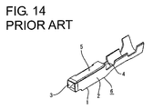
- FIG. 14 One example of a terminal fitting provided with a main portion in the form of a rectangular tube is known from Japanese Unexamined Patent Publication No. 4-209471.
- This terminal fitting is, as shown in FIG. 14, provided with a main portion 6 comprised of a bottom wall 1 narrow and long in forward and backward directions, a pair of side walls 2, 3 standing up from the opposite lateral ends of the bottom wall 1, a ceiling wall 4 projecting from the upper end of the right side wall 2 in FIG. 14 to face the bottom wall 1, and an outer wall 5 projecting from the left side wall 3, placed on the outer side of the ceiling wall 4 and having its projecting end brought into abutment against the upper end of the right side wall 2.
- the outer wall 5 cantilevers from the left side wall 3. Accordingly, if a certain external force acts on this outer wall 5, the outer wall 5 may be, for example, deformed to open outward. If this happens, the main portion 6 cannot be held in the shape of a rectangular tube.
- the present invention was developed in view of the above problem and an object thereof is to hold a main portion in a specified shape.
- a terminal fitting provided with a main portion formed into the shape of a substantially rectangular tube by bending a base member substantially along longitudinal direction, wherein:
- the walls having the holding piece and the holding groove can be held while being prevented from loose movements along longitudinal directions with respect to each other by the engagement of the holding piece with the holding groove.
- the holding piece comprises at least one restrictable portion and the holding groove comprises at least one restricting portion for restricting an opening deformation of the wall having the holding piece by the engagement with the restrictable portion.
- a terminal fitting provided with a main portion formed into the shape of a substantially rectangular tube by bending a base member along longitudinal direction, wherein:
- the walls having the holding piece and the holding groove can be held while being prevented from loose movements along longitudinal directions with respect to each other by the engagement of the holding piece with the holding groove, and the opening deformation of the wall having the holding piece can be restricted by the engagement of the restricting portion with the restrictable portion.
- the main portion can be held in the shape of a substantially rectangular tube.
- the wall having the holding piece can lock the terminal fitting by the engagement with a fastening portion provided in a connector housing when the terminal fitting is at least partly inserted into the connector housing preferably from behind, and/or the restrictable portion and the restricting portion are provided at the rear ends of the holding piece and the holding groove, respectively.
- the wall having the holding piece is formed with a cut-away portion to permit the entrance of the fastening portion, the fastening portion is engageable with a cut end surface preferably at the front side of the cut-away portion, the wall is divided into a front portion and a rear portion by the cut-away portion, and/or the holding piece and the restrictable portion are provided at the front portion of the wall where the fastening portion is engageable.
- the terminal fitting can be locked by the engagement of the fastening portion having entered the cut-away portion with the front cut end surface of the cut-away portion. Since the cut-away portion is formed in such a range as to divide the wall into the front and rear portions, a large engaging area with the fastening portion can be ensured. Therefore, a sufficient locking force can be obtained even if the terminal fitting has a small size.
- the terminal fitting in which the wall is divided into the front and rear portions by the cut-away portion, the front portion engaged with the fastening portion is likely to make loose movements along longitudinal direction and to undergo a twisting movement due to lacking strength.
- the terminal fitting suited to being miniaturized can be provided according to the present invention.
- an auxiliary restrictable portion is provided at the front end of the holding piece, and an auxiliary restricting portion for restricting the opening deformation of the wall having the holding piece by the engagement with the auxiliary restrictable portion is provided at the holding groove, preferably at the front end of the holding groove.
- the wall having the holding groove and the restricting portion is formed with a bead for reinforcement by embossing.
- the strength of the wall is reduced by forming the holding groove in this wall, it can be improved by providing the bead.
- a connector having a connector housing provided with one or more cavities, wherein one or more terminal fittings according to the invention or an embodiment thereof are at least partly inserted into the respective cavity.
- the wall of the terminal fitting having the holding piece can lock the terminal fitting by the engagement with a fastening portion provided in the connector housing when the terminal fitting is at least partly inserted into the connector housing preferably from behind.
- a method for producing a terminal fitting comprising the following steps:
- the holding piece is formed such as to comprise at least one restrictable portion and the holding groove is formed such as to comprise at least one restricting portion, and wherein the restricting portion is brought into engagement with the restrictable portion thereby restricting an opening deformation of the wall having the holding piece.
- the restrictable portion and the restricting portion are provided at the rear ends of the holding piece and the holding groove, respectively.
- FIGS. 1 to 12 A first preferred embodiment of the present invention is described with reference to FIGS. 1 to 12.
- one or more female terminal fittings 30 at least partly insertable into a female connector housing 10 (hereinafter, merely “female housing 10"). While being at least partly accommodated in the female housing 10, the female terminal fittings 30 are electrically connectable with male terminal fittings at least partly accommodated in a mating male housing (neither male terminal fittings nor male housing is shown) to be connected with the female housing 10.
- directions IWD of inserting and withdrawing the female terminal fittings 30 into and from the female housing 10 are referred to as a forward direction and a backward direction, respectively, and reference is made to FIG. 4 concerning vertical direction.
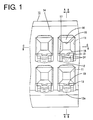
- a plurality of cavities 11 into which the female terminal fittings 30 are at least partly insertable along the inserting and withdrawing directions IWD, preferably from behind, are arranged substantially side by side along widthwise direction at one or more, e.g. two stages as shown in FIGS. 1 and 4.
- the female terminal fitting 30 at least partly inserted into the cavity 11 can be resiliently locked preferably by a locking portion 13 projecting from a bottom or lateral wall 12 of the cavity 11 and can be supported at its front-limit position by the front wall 14 of the female housing 10.
- the front wall 14 of the female housing 10 is formed with tab insertion holes 15 for permitting tabs of the mating male terminal fittings to be inserted into the cavities 11 from front, and conical or slanted or converging or tapered guide surfaces 16 are formed at the front edges of the tab insertion holes 15 preferably over the substantially entire circumference, so that the insertion of the tabs can be smoothly guided.
- mold-removal holes 17 used to remove the front mold for forming the locking portion 13 at the time of molding the female housing 10 forward are formed.
- a substantially triangular projecting portion 18 projecting down is formed, and the guide surface 16 is continuously formed at the projecting portion 18, too.
- each cavity 11 About 1/4 of a front portion of the bottom wall 12 of each cavity 11 is formed to be lower or projecting downward to form a stepped or lowered portion 12a, and the cantilever-shaped locking portion 13 projects forward from a resulting stepped or lowered portion 12a.
- This locking portion 13 is inclined upward to the front as a whole so as to gradually project upward, i.e. into the cavity 11, toward its front end, and is resiliently deformable downward or laterally in a deformation direction DD (direction DD intersecting with the inserting and withdrawing directions IWD of the female terminal fitting 30) about a base end (rear end) as a supporting point when a portion thereof projecting into the cavity 11 is pressed by the female terminal fitting 30 being inserted.
- DD deformation direction
- the locking portion 13 is retracted into a deformation permitting space defined in a lowered portion 12a of the bottom wall 12.
- a locking projection 52 of the female terminal fitting 30 can enter a space provided before the locking portion 13.
- the lowered portion 12a of the bottom wall 12 substantially facing the locking portion 13 from below prevents an excessive resilient deformation of the locking portion 13 by being brought into engagement with the lower surface of the locking portion 13 at a stage before the locking portion 13 undergoes a resilient deformation beyond its resiliency limit.
- the locking portion 13 is covered by the lowered portion 12a of the bottom wall 12 connected with the front wall 14 over the substantially entire width without being exposed to the cavity 11 located below or to the outside below the female housing 10, thereby being protected.
- a projection-inserting groove 19 along or into which the locking projection 52 and a projection 49 of the female terminal fitting 30 are at least partly insertable is formed preferably substantially in the widthwise center of the bottom wall 12, and a stabilizer-inserting groove 20 along or into which a stabilizer 47 of the female terminal fitting 30 is at least partly insertable and which is deeper or radially recessed more than the projection-inserting groove 19 is formed at the back side of the projection-inserting groove 19 in FIG. 7.
- the projection-inserting groove 19 is formed to be continuous with the front end of the locking portion 13, whereas the front end position of the stabilizer-inserting groove 20 is set at a position slightly behind the locking portion 13.
- the bottom wall 12, the projection-inserting groove 19 and the stabilizer-insertion groove 20 define a stair-like shape in widthwise or lateral direction.
- a pair of maneuverable recesses 24 maneuverable by a disengagement jig (not shown) to forcibly resiliently deform the locking portion 13 are formed to be open forward at about 3/5 of the total height of the opposite sides of the front end of the locking portion 13 at the lower parts thereof.
- the maneuverable recesses 24 are so arranged as to be exposed forward to outside even if the female terminal fitting 30 is locked by the locking portion 13, and can be pressed down or in the deformation direction DD by the disengagement jig inserted through the mold-removal hole 17 from front.
- Each maneuverable recess 24 is formed to be substantially triangular when the locking portion 13 is viewed sideways, and the upper surface thereof is substantially horizontal, whereas the lower surface thereof is inclined upward to the back.
- the female terminal fitting 30 is formed into a desired shape by, for example, embossing, folding and/or bending a metallic material stamped or cut out into a specified (predetermined or predeterminable) shape.
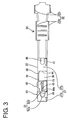
- This female terminal fitting 30 is, as shown in FIGS. 3 and 4, roughly constructed such that a main portion 31 substantially in the form of a substantially rectangular or box-shaped tube and a barrel portion 32 to be crimped or bent or folded into connection with an end of a wire W are connected one after the other.
- the barrel portion 32 is comprised of two front and rear pairs of crimping pieces 32a, 32b, wherein the front pair of crimping pieces 32a are crimped or bent or folded into connection with a core Wa of the wire W, and the rear pair of crimping pieces 32b are crimped into connection with an insulated portion Wb of the wire W.
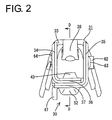
- the main portion 31 is formed into a substantially rectangular tube as shown in FIG. 2 by bending, folding and/or embossing a piece of a metallic base material stamped or cut out into a specified (predetermined or predeterminable) shape (corresponding to a base member) substantially along longitudinal direction of the terminal fitting 30.
- the main portion 31 is comprised of a ceiling wall 33 extending in forward and backward or longitudinal directions, a pair of side walls 34, 35 extending down from the opposite lateral edges or edge portions of the ceiling wall 33, a bottom wall 36 projecting from the projecting end of the left side wall 34 of FIG. 2 to face the ceiling wall 33, and an outer wall 37 projecting from the projecting end of the right side wall 34 of FIG. 2 to be at least partly placed below or outside of the bottom wall 36.
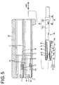
- the front end of the ceiling wall 33 is located at a position retracted backward (or away from a mating side of the terminal fitting 30 with a mating terminal fitting) as compared to those of the other walls 34, 35, 36 and 37, and a resilient contact piece 38 projects from this front end as shown in FIG 5.
- the resilient contact piece 38 is formed to be supported preferably at one end and have a substantially triangular or bent shape by folding a tongue piece projecting forward from the front end of the ceiling wall 33.
- the resilient contact piece 38 can be resiliently brought into contact with the tab of the mating male terminal fitting at least partly inserted into the main portion 31 from front.
- an excessive deformation preventing portion 42 for preventing an excessive resilient deformation of the resilient contact piece 38 by engaging the resilient contact piece 38 before the resilient contact piece 38 is deformed beyond its resiliency limit or damagig it is formed preferably by embossing the ceiling wall 33 to project inward.
- the outer wall 37 is divided into a front portion 37a and a rear portion 37b by a cut-away portion 44 formed preferably over the substantially entire width substantially at its longitudinal middle portion.
- the lock portion 13 can enter this cut-away portion 44 over its entire length and can be engaged with a front cut end surface 44a of the cut-away portion 44.
- the front cut end surface 44a of the cut-away portion 44 which surface serves as a locking surface engageable with the locking portion 13 is inclined upward to the back over its entire area.
- This cut-away portion 44 has a length slightly shorter than half the length of the outer wall 37 and extends up to the bottom end of the side wall 35 at the upper side in FIG. 3.
- a bulging piece 45 projecting from the projecting end of the bottom wall 36 is brought into contact with the bottom end surface (cut end surface of the cut-away portion 44 at the side) of this side wall 35 to hold the bottom wall 36 substantially horizontally.
- the front half of the bottom wall 36 including the receiving portion 43 is formed with a recess 55 so as to be slightly lower than the rear half thereof.
- the recess 55 is formed preferably over the substantially entire area including a portion of the bulging piece 45 in contact with the side wall 35.
- a depth of engagement of the locking portion 13 can be preferably enlarged by the presence of the recess 55.
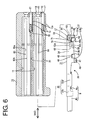
- This recess 55 is formed over the area extending to the upper end of the side wall 34, and the rear end surface of the front-portion holding piece 50 substantially faces or is adjacent to or is directed to the recess 55 from front as shown in FIG. 6.
- the front portion 37a of the outer wall 37 is slightly shorter than the rear portion 37b in forward and backward or longitudinal directions.
- a rear-portion holding piece 46 bent toward the ceiling wall 33 (inward direction) and the stabilizer 47 bent in an opposite direction (outward direction) are provided one after the other at the projecting end of the rear portion 37b of the outer wall 37.
- the rear-portion holding piece 46 holds the rear portion 37b while preventing the rear portion 37b from making loose forward and backward movements (or movements along the longitudinal direction of the terminal fitting 30) by being fitted into a rear-portion holding groove 48 formed in the side wall 34 shown in FIG. 6.
- the stabilizer 47 can guide the insertion of the female terminal fitting 30 by being inserted along the stabilizer-inserting groove 20 in the cavity 11.
- the front end of the rear-portion holding piece 46 and the front end of the rear portion 37b are substantially aligned with each other, whereas the rear end of the stabilizer 47 and the rear end of the rear portion 37b are substantially aligned with each other.
- a widthwise center portion of the rear end of the rear portion 37b is embossed to project outward, thereby forming a projection 49 having a length substantially equal to that of the stabilizer 47. This projection 49 can be brought into contact with the bottom surface of the cavity 11 (upper surface of the projection-inserting groove 19) when the female terminal fitting 30 is inserted into the cavity 11.
- the locking projection 52 is, as shown in FIGS. 3 and 4, substantially in the form of a pyramid having a vertex at its front end and is tapered toward its front end so that the width and height thereof gradually decrease.
- the locking projection 52 is such that a pyramid or parallelepipedic portion 52a formed by three or more slanted surfaces and a substantially rectangular tube portion 52b substantially having constant width and height and formed by three or more side surfaces are connected one after the other.
- the pyramid portion 52a of the locking projection 52 is tapered and preferably has its front end slightly rounded, so that the locking projection 52 can be smoothly inserted along the projection-inserting groove 19 in the process of at least partly inserting the female terminal fitting 30 into the cavity 11.
- the rectangular tube portion 52b of the locking projection 52 is formed to overhang or project backward substantially along the inclination of the front cut end surface 44a of the cut-away portion 44 and projects more backward than the front portion 37a of the outer wall 37.
- the locking projection 52 is substantially parallel to the front cut end surface 44a which overhangs or is undercut or is back tapered so as to be inwardly inclined (or inclined at an angle with respect to the insertion and withdrawal directions IWD, the angle being preferably acute or between 0° and 90° with respect to the area or plane defined by the cut-away portion 44).
- This locking projection 52 projects up to the substantially same height as the projection 49, and is at least partly insertable into the projection-inserting groove 19 of the cavity 11 similar to the projection 49.
- the rear end surface or rear end 52c of the locking projection 52 serving as a locking surface engageable with the locking portion 13 is formed by the front cut end surface 44a of the cut-away portion 44 and is inclined inwardly or upward to the back.
- the rear end surfaces of the portions of the front portion 37a of the outer wall 37 at the opposite sides of the locking projection 52 are also formed by the front cut end surface 44a of the cut-away portion 44 inclined inwardly or upward to the back and is engageable with the locking portion 13.
- a front-portion holding piece or projection 50 bent toward the ceiling wall 33 is provided at the projecting end (end abutting against the side wall 34) of the front portion 37a of the outer wall 37 as shown in FIG. 6.
- the front-portion holding piece 50 holds the front portion 37a while preventing the front portion 37a from making loose forward and backward or longitudinal movements by being fitted into a front-portion holding groove or recess or hole 51 formed in the side wall 34 shown in FIG. 6.
- This front-portion holding piece 50 projects more backward than the front portion 37a of the outer wall 37.
- the cut-away portion 44 extends into the base end of the front-portion holding piece 50, and the cut end surface 44a thereof is inclined inwardly or upward to the back as already described. A side end of the locking portion 13 is engageable with this cut end surface 44a.
- a restrictable projection 70 preferably projects backward from the rear end of the projecting end of the front-portion holding piece 50, and a restricting groove or recess or hole 71 engageable with the restrictable projection 70 preferably is provided at the rear or backward end (end opposite to a mating side of the terminal fitting 30 with a mating terminal fitting) of the upper or projecting or distal end of the front-portion holding groove 51.
- the lower surfaces of the restricting projection 70 and the restricting groove 71 are preferably formed into slanted surfaces inclined forward.
- the restricting projection 71 preferably is substantially triangularly or pointedly shaped and preferably having an acute angle oriented backward in the terminal fitting 30.
- the restrictable projection 70 and the restricting groove or recess or hole 71 preferably substantially have a corresponding or complementary shape so as to be engageable with each other.
- the restrictable projection 70 at least partly fitted into the restricting groove 71, the lower surface of the restrictable projection 70 is at least partly engageable with that of the restricting groove 71.
- the upper surfaces of the front or distal end portions of the front-portion holding piece 51 and the front-portion holding groove 51 preferably are formed into slanted surfaces inclined forward.
- the front-portion holding piece 50 is at least partly fitted into the front-portion holding groove 51 and the restrictable projection 70 is at least partly fitted into the restricting groove 71 by bending the front-portion holding piece 50 with respect to the front portion 37a of the outer wall 37 after the front portion 37a is bent with respect to the side wall 35.
- the side wall 34 formed with the front-portion holding groove 51 and the restricting groove 71 is preferably embossed at a position above the front-portion holding groove 51 and the restricting groove 71 to project outward, thereby forming a second bead 64 having an elliptical shape long in forward and backward or longitudinal directions.
- This second bead 64 reinforces the side wall 34.
- the surface of the front half of the cavity 11 at the back side of FIG. 4 is recessed to form an escaping groove 61 for escaping the second bead 64 during the insertion of the female terminal fitting 30, the escaping groove 61 having an open rear end.
- This escaping groove 61 preferably has such an arcuate shape substantially as to conform to the second bead 64, and is located at a position of the side surface of the cavity 11 slightly above the center position with respect to vertical direction, and the front end position thereof is located slightly more forward than that of a supporting groove 60 to be described later.
- This female connector is provided with means for preventing the female terminal fitting 30 inserted into the cavity 11 from vertically inclining.
- the female housing 10 is described concerning this means.
- the supporting groove 60 having an open rear end is formed by recessing the inner surface of the cavity 11 at the back side of FIG. 6 substantially extending along vertical direction (deforming direction DD of the locking portion 13).
- This supporting groove 60 is formed to have such a substantially rectangular shape as to conform to a supportable projection 62 to be described later, and is located substantially at the middle position of the side surface of the cavity 11 with respect to vertical direction, and the front end position thereof is located slightly more backward than the front surface of the cavity 11.
- Upper and lower surfaces 60a, 60b of the supporting groove 60 are formed straight along widthwise direction which is a direction at an angle different from 0° or 180°, preferably substantially normal to the deforming direction DD of the locking portion 13.
- the supportable projection 62 at least partly fittable into the supporting groove 60 projects outward from the right side wall 35 of FIG. 2 forming the main portion 31.
- the supportable projection 62 is formed preferably by embossing a part of the side wall 35 to project outward and is in the form of a beam supported at both ends by having the front and rear ends thereof coupled to the side wall 35, and has its upper and lower sides extending along forward and backward or longitudinal directions (direction at an angle different from 0° or 180°, preferably substantially normal to the deforming direction DD of the locking portion 13) separated from the side wall 35.
- Front and rear portions of the supportable projection 62 raised from the side wall 35 are inclined with respect to the side wall 35, wherein the front end surface of the supportable projection 62 is formed into a slanted surface inclined backward and the rear end surface thereof is formed into a slanted surface inclined forward.
- the female terminal fitting 30 can be smoothly inserted into and withdrawn from the cavity 11.
- Upper and lower surfaces 62a, 62b of the supportable projection 62 are cut end surfaces separated from the side wall 35 and extend substantially horizontally, i.e. extend substantially straight along forward and backward or longitudinal directions and widthwise direction (direction at an angle different from 0° or 180°, preferably substantially normal to the deforming direction DD of the locking portion 13).
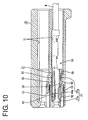
- the supportable projection 62 When the supportable projection 62 is fitted into the supporting groove 60 as the female terminal fitting 30 is at least partly inserted into the cavity 11, the upper and lower surfaces 62a, 62b of the supportable projection 62 are engaged with the upper and lower surfaces 60a, 60b of the supporting groove 60 (see FIG. 11).
- the supportable projection 62 is located at a position of the side wall 35 which position is substantially in the center with respect to vertical direction and slightly more forward than the center with respect to forward and backward or longitudinal directions (but behind the locking projection 52), and a vertical dimension (height) thereof is about 1/4 of that of the main portion 31.
- the side wall 35 is embossed at a position before the supportable projection 62 to project outward, thereby forming a first bead 63 having an elliptical or rounded or oval shape long or elongated in forward and backward or longitudinal directions.
- the first bead 63 reinforces the side wall 35.
- the first bead 63 is located within a width range of the supportable projection 62, which range extends along vertical direction, and an out-ward-projecting height thereof is set lower than that of the supportable projection 62, so that the first bead 63 can be inserted into the supporting groove 60 when the female terminal fitting 30 is inserted into the cavity 11.
- the side walls 34, 35 extend more forward than the ceiling wall 33 as described above.
- up-ward-opening slits 54 are formed in the side walls 34, 35 substantially at the same position as the front end position of the ceiling wall 33 in order to prevent the influence of bending on the extended portions of the side walls 34, 35 (see FIGS. 4 and 6).
- Such slits 54 reduce the strengths of the side walls 34, 35.
- the first bead 63 is provided on a virtual line L1 connecting the slit 54 of the side wall 35 and the cut-away portion 44 at a shortest distance and the second bead 64 is provided on a virtual line L2 connecting the slit 54 of the side wall 34 and the front-portion holding groove 51, a reduction in the strengths of the side walls 34, 35 can be effectively complemented.
- the female terminal fitting 30 is at least partly inserted into the cavity 11 preferably from behind after the barrel portion 32 of the female terminal fitting 30 is crimped or bent or folded into connection with the wire W.
- the locking projection 52 is at least partly inserted into the projection-inserting groove 19
- the second bead 64 enters the escaping groove 61
- the first bead 63 and the supportable projection 62 are successively at least partly fitted into the supporting groove 60.
- the projection 49 and the stabilizer 47 are at least partly introduced into the projection-inserting groove 19 and the stabilizer-inserting groove 20, respectively, whereby the female terminal fitting 30 can be smoothly inserted while being prevented from shaking along vertical and transverse directions.
- the locking portion 13 is pressed down or deflected in the deforming direction DD by the locking projection 52, thereby being resiliently deformed as shown in FIG. 8.
- the locking portion 13 is resiliently deformed to a maximum degree when the front part 13a is pressed by the locking projection 52.
- the locking projection 52 can be smoothly inserted substantially along the projection-inserting groove 19 and can smoothly press the locking portion 13 by being formed into a substantially pyramidal shape having a vertex at the front end.
- the locking projection 52 moves beyond the locking portion 13 and the locking portion 13 is resiliently restored to resiliently lock the female terminal fitting 30 while entering the cut-away portion 44 as shown in FIGS. 9 to 12.
- the front end of the locking portion 13 can enter the inside of the locking projection 52.
- the supportable projection 62 is at least partly fitted into the supporting groove 60, and the upper and lower surfaces 60a, 60b, 62a, 62b of the supporting groove 60 and the supportable projection 62 are engaged with each other (see FIG. 11). Accordingly, even if, for example, a pulling force acts on the wire W, the female terminal fitting 30 is prevented from vertical inclinations.
- the upper and lower surfaces 62a, 62b of the supportable projection 62 are cut end surfaces substantially straight along horizontal direction or longitudinal direction of the terminal fitting 30 by being separated from the side wall 35, the female terminal fitting 30 can be firmly supported and the inclination thereof can be securely prevented.
- the front cut end surface 44a of the cut-away portion 44 which is the locking surface engageable with the locking portion 13 is formed to reach the front portion 37a of the outer wall 37 including the locking projection 52 and the front-portion holding piece 50, i.e. formed substantially over the entire width area of the female terminal fitting 30.
- the female terminal fitting 30 is held with a strong locking force so as not to come out of the cavity 11 (see FIG 12). Further, since the front cut end surface 44a of the cut-away portion 44 is inclined upward to the back, the locking force is even stronger.
- a force may act on the female terminal fitting 30 via the wire W to pull the female terminal fitting 30 backward.
- the front portion 37a of the outer wall 37 directly engaged with the locking portion 13 is subjected to such a force as to displace the entire front portion 37a forward and such a force as to twist the rear end of the front portion 37a downward with the front end thereof as a supporting point.
- the front-portion holding piece 50 is fitted into the front-portion holding groove 51 to engage the front surfaces of these 50, 51 with each other, the front portion 37a of the outer wall 37 is prevented from making loose forward movements with respect to the side wall 34.
- the restrictable projection 70 is preferably at least partly fitted into the restricting groove 71 to engage the lower surfaces of these 70, 71 with each other, the front portion 37a of the outer wall 37 is prevented from undergoing such an opening deformation as to be twisted downward (see FIG. 11).
- the main portion 31 can be held in the specified shape of a substantially rectangular tube.
- the front portion 37a of the outer wall 37 and the side wall 34 can be held while being prevented from making loose movements along forward and backward directions (longitudinal direction) with respect to each other by fitting the front-portion holding piece 50 into the front-portion holding groove 51, and the front portion 37a of the outer wall 37 can be prevented from undergoing such a deformation as to open outward by the engagement of the restrictable projection 70 and the restricting groove 71.
- the main portion 31 can be held in the shape of a substantially rectangular tube.
- a force acts to pull the female terminal fitting 30 backward with the front portion 37a of the outer wall 37 engaged with the locking portion 13 after the female terminal 30 is at least partly inserted into the cavity 11, a force acts on the front portion 37a to twist the rear end of the front portion 37a with the front end thereof as a supporting point.
- the restrictable projection 70 and the restricting groove 71 are preferably provided at the rear ends of the front-portion holding piece 50 and the front-portion holding groove 51, respectively, a twisting displacement of the front portion 37a can be effectively restricted. Therefore, the female terminal fitting 30 can be stably fastened by the locking portion 13.
- the cut-away portion 44 is formed in such a range as to divide the outer wall 37 into the front and rear portions 37a, 37b, a large engaging area can be secured for the locking portion 13 and a sufficient locking force can be obtained even if the female terminal fitting 30 has a small size. Since the outer wall 37 divided into the front and rear portions 37a, 37b by the cut-away portion 44 has a reduced strength, the front portion 37a engaged with the locking portion 13 is likely to make loose movements along longitudinal direction and to undergo a twisting deformation. However, an occurrence of such an undesirable event can be prevented by the front-portion holding piece 50 and the restrictable projection 70. In other words, the female terminal fitting 30 suited to being miniaturized can be provided according to this embodiment.
- the second bead 64 is provided to reinforce the side wall 35, a reduction in the strength of the side wall 34 caused by forming the front-portion holding groove 51 and the restricting groove 71 can be complemented.
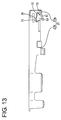
- FIG. 13 A second preferred embodiment of the present invention is described with reference to FIG. 13.
- an auxiliary restrictable projection 72 and an auxiliary restricting groove 73 are provided at the front ends of the front-portion holding piece 50 and the front-portion holding groove 51, respectively. It should be noted that, in the second embodiment, no repetitive description is made on the same or similar construction as the first embodiment by identifying it by the same reference numerals.
- the auxiliary restrictable projection 72 projects forward from the upper front end of the front-portion holding piece 50, and the auxiliary restricting groove 73 engageable with the auxiliary restrictable projection 72 is provided at the upper front end of the front-portion holding groove 51.
- the lower surfaces of the auxiliary restrictable projection 72 and the auxiliary restricting groove 73 are formed into slanted surfaces inclined forward or toward the mating side of the terminal fitting 30 with a mating terminal fitting.
- the restrictable projection 70 and the restricting groove 71 are engaged with each other at the rear side and the auxiliary restrictable projection 72 and the auxiliary restricting groove 73 are engaged with each other at the front side, whereby the outward opening (twisting) deformation of the front portion 37a of the outer wall 37 can be securely prevented.
- a main portion 31 is formed into the shape of a substantially rectangular tube by bending a piece of a metallic base material stamped out into a specified shape substantially along longitudinal direction.
- the main portion is comprised of a ceiling 33 extending in forward and backward or longitudinal directions, a pair of side walls 34, 35 extending down from the opposite lateral ends of the ceiling wall 33, a bottom wall 36 projecting from the projecting end of the side wall 34 to face the ceiling wall 33, and an outer wall 37 projecting from the projecting end of the side wall 35 and placed on the outer side of the bottom wall 36.
- a front-portion holding piece 50 projects from a front portion 37a of the outer wall 37, and a front-portion holding groove 51 engageable with the front-portion holding piece 50 is formed in the side wall 34.
- a restrictable projection 70 is provided at the rear end of the front-portion holding piece 50, and the front-portion holding groove 51 is formed with a restricting groove 71 for restricting an opening deformation of the front portion 37a of the outer wall 37 having the front-portion holding piece 50 by the engagement with the restrictable projection 70.
Landscapes
- Engineering & Computer Science (AREA)
- Manufacturing & Machinery (AREA)
- Connector Housings Or Holding Contact Members (AREA)
- Manufacturing Of Electrical Connectors (AREA)
Abstract
Description
- 10
- female housing (connector housing)
- 13
- locking portion (fastening portion)
- 30
- female terminal fitting (terminal fitting)
- 31
- main portion
- 34
- side wall (wall having a holding groove)
- 37a
- front portion (wall having a holding piece)
- 44
- cut-away portion
- 50
- front-portion holding piece (holding piece)
- 51
- front-portion holding groove (holding groove)
- 64
- second bead (bead)
- 70
- restrictable projection (restrictable portion)
- 71
- restricting groove (restricting portion)
- 72
- auxiliary restrictable projection (auxiliary restrictable portion)
- 73
- auxiliary restricting groove (auxiliary restricting portion)
Claims (13)
- A terminal fitting (30) provided with a main portion (31) formed into the shape of a substantially rectangular tube by bending a base member substantially along longitudinal direction, wherein:at least one holding piece (50) projects at least from one of ends of the main portion (31) to be brought at least partly into abutment and a holding groove (51) engageable with the holding piece (50) is formed in the other of the ends, whereby walls (34, 37) of the main portion (31) having the holding piece (50) and the holding groove (51) are prevented from being loosely moved along longitudinal direction.
- A terminal fitting according to claim 1, wherein the holding piece (50) comprises at least one restrictable portion (70) and the holding groove (51) comprises at least one restricting portion (71) for restricting an opening deformation of the wall (37) having the holding piece (50) by the engagement with the restrictable portion (70).
- A terminal fitting according to claim 2, wherein the restrictable portion (70) and the restricting portion (71) are provided at the rear ends of the holding piece (50) and the holding groove (51), respectively.
- A terminal fitting according to one or more of the preceding claims, wherein the wall (37) having the holding piece (50) can lock the terminal fitting (30) by the engagement with a fastening portion (13) provided in a connector housing (10) when the terminal fitting (30) is at least partly inserted into the connector housing (10) preferably from behind.
- A terminal fitting according to claim 4, wherein the wall (37) having the holding piece (50) is formed with a cut-away portion (44) to permit the entrance of the fastening portion (13), the fastening portion (13) is engageable with a cut end surface (44a) preferably at the front side of the cut-away portion (44), the wall (37) is divided into a front portion and a rear portion by the cut-away portion (44).
- A terminal fitting according to claim 5, wherein the holding piece (50) and the restrictable portion (70) are provided at the front portion of the wall (37) where the fastening portion (13) is engageable.
- A terminal fitting according to one or more of the preceding claims, wherein an auxiliary restrictable portion (72) is provided at the front end of the holding piece (50), and an auxiliary restricting portion (73) for restricting the opening deformation of the wall (37) having the holding piece (50) by the engagement with the auxiliary restrictable portion (72) is provided at the holding groove (51), preferably at the front end of the holding groove (51).
- A terminal fitting according to one or more of the preceding claims, wherein the wall (34) having the holding groove (51) and preferably the restricting portion (71) is formed with at least one bead (64) for reinforcement preferably by embossing.
- A connector having a connector housing (10) provided with one or more cavities (11), wherein one or more terminal fittings (30) according to one or more of the preceding claims are at least partly inserted into the respective cavity.
- A connector according to claim 9, wherein the wall (37) of the terminal fitting (30) having the holding piece (50) can lock the terminal fitting (30) by the engagement with a fastening portion (13) provided in the connector housing (10) when the terminal fitting (30) is at least partly inserted into the connector housing (10) preferably from behind.
- A method for producing a terminal fitting (30), comprising the following steps:wherein at least one holding piece (50) projects at least from one of ends of the main portion (31) to be brought at least partly into abutment and a holding groove (51) engageable with the holding piece (50) is formed in the other of the ends, whereby walls (34, 37) of the main portion (31) having the holding piece (50) and the holding groove (51) are prevented from being loosely moved along longitudinal direction.providing a base member having a specified shape;forming a main portion (31) into the shape of a substantially rectangular tube by bending the base member substantially along longitudinal direction,
- A method according to claim 11, wherein the holding piece (50) is formed such as to comprise at least one restrictable portion (70) and the holding groove (51) is formed such as to comprise at least one restricting portion (71), and wherein the restricting portion (71) is brought into engagement with the restrictable portion (70) thereby restricting an opening deformation of the wall (37) having the holding piece (50).
- A method according to claim 12, wherein the restrictable portion (70) and the restricting portion (71) are provided at the rear ends of the holding piece (50) and the holding groove (51), respectively.
Applications Claiming Priority (6)
| Application Number | Priority Date | Filing Date | Title |
|---|---|---|---|
| JP2001272453A JP3801889B2 (en) | 2001-09-07 | 2001-09-07 | Terminal fitting |
| JP2001272453 | 2001-09-07 | ||
| JP2002166360 | 2002-06-06 | ||
| JP2002166360A JP3415132B1 (en) | 2002-06-06 | 2002-06-06 | Terminal fittings and connectors |
| JP2002183604A JP3415139B1 (en) | 2002-06-24 | 2002-06-24 | Terminal fitting |
| JP2002183604 | 2002-06-24 |
Publications (3)
| Publication Number | Publication Date |
|---|---|
| EP1294056A2 true EP1294056A2 (en) | 2003-03-19 |
| EP1294056A3 EP1294056A3 (en) | 2003-04-16 |
| EP1294056B1 EP1294056B1 (en) | 2007-02-14 |
Family
ID=27347460
Family Applications (1)
| Application Number | Title | Priority Date | Filing Date |
|---|---|---|---|
| EP02019457A Expired - Lifetime EP1294056B1 (en) | 2001-09-07 | 2002-08-30 | Terminal fitting, connector provided therewith and method for producing the terminal fitting |
Country Status (3)
| Country | Link |
|---|---|
| US (1) | US6752660B2 (en) |
| EP (1) | EP1294056B1 (en) |
| DE (1) | DE60218094T2 (en) |
Cited By (3)
| Publication number | Priority date | Publication date | Assignee | Title |
|---|---|---|---|---|
| EP1378968B1 (en) * | 2002-07-04 | 2007-11-07 | Sumitomo Wiring Systems, Ltd. | A connector |
| WO2012111859A1 (en) * | 2011-02-18 | 2012-08-23 | Yazaki Corporation | Joint connector |
| FR3022409A1 (en) * | 2014-06-12 | 2015-12-18 | Dai Ichi Seiko Co Ltd | ELECTRICAL TERMINAL. |
Families Citing this family (15)
| Publication number | Priority date | Publication date | Assignee | Title |
|---|---|---|---|---|
| JP4122144B2 (en) * | 2001-09-18 | 2008-07-23 | 住友電装株式会社 | Terminal fitting |
| DE10252832B4 (en) * | 2001-11-22 | 2006-11-30 | Sumitomo Wiring Systems, Ltd., Yokkaichi | Terminal fitting and method of forming the same |
| JP2005019282A (en) * | 2003-06-27 | 2005-01-20 | Sumitomo Wiring Syst Ltd | Connector |
| JP4013151B2 (en) * | 2004-04-13 | 2007-11-28 | 住友電装株式会社 | Female terminal bracket |
| JP4356567B2 (en) * | 2004-09-09 | 2009-11-04 | 住友電装株式会社 | connector |
| US7232339B1 (en) * | 2006-05-19 | 2007-06-19 | Molex Incorporated | Sealed electrical connector |
| JP4743109B2 (en) * | 2006-12-18 | 2011-08-10 | 住友電装株式会社 | Terminal fittings and connectors |
| JP5233822B2 (en) * | 2009-04-24 | 2013-07-10 | 住友電装株式会社 | Terminal fitting |
| JP2013229222A (en) * | 2012-04-26 | 2013-11-07 | Sumitomo Wiring Syst Ltd | Terminal fitting |
| DE102013004403A1 (en) * | 2012-04-26 | 2013-10-31 | Sumitomo Wiring Systems, Ltd. | Terminal fitting and method of making the same |
| JP6211563B2 (en) | 2015-07-31 | 2017-10-11 | 矢崎総業株式会社 | Terminal bracket |
| JP2018018703A (en) | 2016-07-28 | 2018-02-01 | 矢崎総業株式会社 | connector |
| JP6729273B2 (en) * | 2016-10-12 | 2020-07-22 | 株式会社オートネットワーク技術研究所 | Connector structure |
| JP6781934B2 (en) | 2017-04-26 | 2020-11-11 | 住友電装株式会社 | Terminal |
| JP6889842B2 (en) * | 2018-02-26 | 2021-06-18 | 住友電装株式会社 | connector |
Family Cites Families (17)
| Publication number | Priority date | Publication date | Assignee | Title |
|---|---|---|---|---|
| US4047791A (en) * | 1974-12-06 | 1977-09-13 | Amp Incorporated | Low insertion force receptacle and cammed housing |
| US4781628A (en) * | 1987-10-22 | 1988-11-01 | General Motors Corporation | Female electrical terminal |
| GB9301465D0 (en) * | 1993-01-26 | 1993-03-17 | Amp Gmbh | Electrical terminal receptacle with improved means for connecting two electrical conducting tables and a method for manufacturing it |
| DE4312641C2 (en) * | 1993-04-19 | 1995-10-12 | Grote & Hartmann | Electrical contact sleeve |
| JP3119418B2 (en) * | 1994-04-20 | 2000-12-18 | 矢崎総業株式会社 | Terminal for waterproof connector |
| FR2741204A1 (en) * | 1995-11-14 | 1997-05-16 | Amp France | ASSEMBLY OF ELECTRICAL CONNECTOR |
| US5911603A (en) * | 1996-07-22 | 1999-06-15 | The Whitaker Corporation | Single piece electrical receptacle terminal for mating with a pin contact |
| DE19651120C1 (en) * | 1996-12-09 | 1998-05-07 | Framatome Connectors Int | Contact elements and connectors, especially for cable harnesses |
| DE19710427C1 (en) * | 1997-03-13 | 1998-10-15 | Kostal Leopold Gmbh & Co Kg | Electrical connector plug |
| DE19741346B4 (en) * | 1997-09-19 | 2007-12-20 | The Whitaker Corp., Wilmington | Dovetail electrical contact and method of making such an electrical contact |
| FR2769413B1 (en) * | 1997-10-03 | 1999-11-26 | Proner Comatel Sa | FEMALE ELECTRIC CONTACT |
| JP3224369B2 (en) * | 1998-07-16 | 2001-10-29 | 日本圧着端子製造株式会社 | Connector terminals and housing |
| JP3468351B2 (en) * | 1998-08-07 | 2003-11-17 | 矢崎総業株式会社 | connector |
| JP3702415B2 (en) * | 1999-09-06 | 2005-10-05 | 矢崎総業株式会社 | Double locking connector |
| JP3544155B2 (en) * | 1999-10-22 | 2004-07-21 | 住友電装株式会社 | Terminal fitting |
| US6244910B1 (en) * | 2000-05-04 | 2001-06-12 | Tyco Electronics Corporation | Electrical box contact with stress limitation |
| JP3576488B2 (en) * | 2000-12-18 | 2004-10-13 | 日本圧着端子製造株式会社 | Female terminal |
-
2002
- 2002-08-30 DE DE60218094T patent/DE60218094T2/en not_active Expired - Lifetime
- 2002-08-30 EP EP02019457A patent/EP1294056B1/en not_active Expired - Lifetime
- 2002-09-09 US US10/238,132 patent/US6752660B2/en not_active Expired - Lifetime
Cited By (3)
| Publication number | Priority date | Publication date | Assignee | Title |
|---|---|---|---|---|
| EP1378968B1 (en) * | 2002-07-04 | 2007-11-07 | Sumitomo Wiring Systems, Ltd. | A connector |
| WO2012111859A1 (en) * | 2011-02-18 | 2012-08-23 | Yazaki Corporation | Joint connector |
| FR3022409A1 (en) * | 2014-06-12 | 2015-12-18 | Dai Ichi Seiko Co Ltd | ELECTRICAL TERMINAL. |
Also Published As
| Publication number | Publication date |
|---|---|
| DE60218094T2 (en) | 2007-11-29 |
| US6752660B2 (en) | 2004-06-22 |
| DE60218094D1 (en) | 2007-03-29 |
| EP1294056B1 (en) | 2007-02-14 |
| EP1294056A3 (en) | 2003-04-16 |
| US20030049965A1 (en) | 2003-03-13 |
Similar Documents
| Publication | Publication Date | Title |
|---|---|---|
| EP1369959B1 (en) | A connector, a disengagement jig and a method | |
| EP1294056B1 (en) | Terminal fitting, connector provided therewith and method for producing the terminal fitting | |
| EP1369962B1 (en) | A terminal fitting and a connector provided therewith | |
| US6835097B2 (en) | Connector | |
| US6733346B2 (en) | Terminal fitting, a connector provided therewith and a method for forming a terminal fitting | |
| EP1369963B1 (en) | A connector and a method for inserting a terminal fitting thereinto | |
| EP1378968A1 (en) | A connector | |
| EP1376768B1 (en) | An electrical connector | |
| EP1369960B1 (en) | A connector, a terminal fitting and a method for inserting a terminal fitting | |
| EP1376769B1 (en) | Connector with resilient locking member | |
| US20110207374A1 (en) | Male terminal fitting | |
| EP1369961B1 (en) | A terminal fitting and a connector | |
| US20040192109A1 (en) | Connector, molding method therefor and molding apparatus therefor | |
| US6953366B2 (en) | Connector | |
| EP1391970B1 (en) | A connector | |
| EP1577981B1 (en) | A connector and a disengagement jig |
Legal Events
| Date | Code | Title | Description |
|---|---|---|---|
| PUAI | Public reference made under article 153(3) epc to a published international application that has entered the european phase |
Free format text: ORIGINAL CODE: 0009012 |
|
| PUAL | Search report despatched |
Free format text: ORIGINAL CODE: 0009013 |
|
| 17P | Request for examination filed |
Effective date: 20020905 |
|
| AK | Designated contracting states |
Kind code of ref document: A2 Designated state(s): AT BE BG CH CY CZ DE DK EE ES FI FR GB GR IE IT LI LU MC NL PT SE SK TR Designated state(s): AT BE BG CH CY CZ DE DK EE ES FI FR GB GR IE IT LI LU MC NL PT SE SK TR |
|
| AX | Request for extension of the european patent |
Extension state: AL LT LV MK RO SI |
|
| AK | Designated contracting states |
Designated state(s): AT BE BG CH CY CZ DE DK EE ES FI FR GB GR IE IT LI LU MC NL PT SE SK TR |
|
| AX | Request for extension of the european patent |
Extension state: AL LT LV MK RO SI |
|
| RIC1 | Information provided on ipc code assigned before grant |
Ipc: 7H 01R 43/16 B Ipc: 7H 01R 13/115 B Ipc: 7H 01R 13/422 A |
|
| 17Q | First examination report despatched |
Effective date: 20030807 |
|
| AKX | Designation fees paid |
Designated state(s): DE FR |
|
| GRAP | Despatch of communication of intention to grant a patent |
Free format text: ORIGINAL CODE: EPIDOSNIGR1 |
|
| GRAS | Grant fee paid |
Free format text: ORIGINAL CODE: EPIDOSNIGR3 |
|
| GRAA | (expected) grant |
Free format text: ORIGINAL CODE: 0009210 |
|
| AK | Designated contracting states |
Kind code of ref document: B1 Designated state(s): DE FR |
|
| REF | Corresponds to: |
Ref document number: 60218094 Country of ref document: DE Date of ref document: 20070329 Kind code of ref document: P |
|
| RIN2 | Information on inventor provided after grant (corrected) |
Inventor name: KAWASE HAJIME Inventor name: ISHIKAWA EYOTARO Inventor name: FUJITA, SHINYA Inventor name: TSUJI TAKESHI Inventor name: KURIMOTO NAOYA Inventor name: NANKOU YUUICHI Inventor name: NAKAMURA HIDETO Inventor name: FUKATSU, YUKIHIRO |
|
| ET | Fr: translation filed | ||
| PLBE | No opposition filed within time limit |
Free format text: ORIGINAL CODE: 0009261 |
|
| STAA | Information on the status of an ep patent application or granted ep patent |
Free format text: STATUS: NO OPPOSITION FILED WITHIN TIME LIMIT |
|
| 26N | No opposition filed |
Effective date: 20071115 |
|
| REG | Reference to a national code |
Ref country code: FR Ref legal event code: PLFP Year of fee payment: 15 |
|
| REG | Reference to a national code |
Ref country code: DE Ref legal event code: R084 Ref document number: 60218094 Country of ref document: DE |
|
| REG | Reference to a national code |
Ref country code: FR Ref legal event code: PLFP Year of fee payment: 16 |
|
| REG | Reference to a national code |
Ref country code: FR Ref legal event code: PLFP Year of fee payment: 17 |
|
| PGFP | Annual fee paid to national office [announced via postgrant information from national office to epo] |
Ref country code: FR Payment date: 20210715 Year of fee payment: 20 |
|
| PGFP | Annual fee paid to national office [announced via postgrant information from national office to epo] |
Ref country code: DE Payment date: 20210720 Year of fee payment: 20 |
|
| REG | Reference to a national code |
Ref country code: DE Ref legal event code: R071 Ref document number: 60218094 Country of ref document: DE |