CROSS REFERENCE TO RELATED APPLICATION
BACKGROUND OF THE INVENTION
(a) Field of the Invention
The present invention relates to an electrochemical element, and
particularly, to an electrochemical element with improved energy density
comprising multiply-stacked electrochemical cells using multi-component
composite films, wherein the multi-component composite films are attached
without forming an interface between a support layer film and a porous gellable
polymer layer.
(b) Description of the Related Art
There has been growing interest in energy storage technology. The
applicable field of the battery has been expanded to cellular phones,
camcorders, and notebook computers, and electric vehicles have recently been
added to this list. Such expansion has led to increased research and
development of batteries with visible outcomes. In this respect, research on
electrochemical elements is one of the fields that has been receiving much
attention, among which rechargeable batteries are the central field of interest.
Recent developments concern designing new batteries and electrodes to
improve capacity and specific energy.
Among the secondary batteries being used, lithium ion batteries
developed in the early 1990s has become increasingly popular because they
have a higher operating voltage and energy density compared to Ni-MH, Ni-Cd,
and sulfuric acid-lead batteries that use an aqueous solution electrolyte.
These lithium ion batteries, however, have safety problems resulting from the
use of organic electrolyte, which causes the batteries to be flammable and
explosive. In addition, lithium ion compounds are difficult to manufacture.
Recent lithium ion polymer batteries have overcome such shortcomings
of the lithium ion batteries, and are anticipated to become the next-generation
batteries. These lithium ion polymer batteries, however, have relatively low
capacity compared to lithium ion batteries, and in particular, they have
insufficient discharging capacity at low temperatures, and thus they need to be
improved.
The capacity of a battery is proportional to the amount of electrode
active material used. Thus, it is extremely important to design a cell structure
that can be filled with as much electrode material as possible within the limited
space of the battery package. The most widely known and used type of cell
structure is a jellyroll-shaped structure used in a cylindrical or a prismatic
battery. Such a structure is prepared by a process of coating and pressing
active electrode material onto a metal foil which is used as a current collector,
followed by cutting it into a shape of a strip having a predetermined width and
length, separating the negative electrodenegative electrode and positive
electrode using the separator film, and then rolling it into a spiral form. Such a
jellyroll structure is widely used for manufacturing cylindrical batteries. This
structure, however, has a small radius of curvature at the center portion of the
spiral, which often results in extreme stresses at the bending surface of the
electrode, often causing exfoliation of the electrode. This facilitates the
deposition of lithium metal at the center portion of the electrode during the
repeated charge and discharge of the battery, which may shorten the lifespan
of the battery while degrading its safety.
Generally, the widely known and used method of manufacturing a thin
prismatic-shaped battery comprises the aforesaid process of rolling the spiral
shaped jellyroll into an oval shape and then compressing it, followed by
inserting it into a rectangular container. This method is not free from the
aforesaid problems of reduced lifespan and safety, but rather it has increased
the problems caused by the decrease in the radius of curvature due to the oval
shape. Also, the problem of reduced performance is greater because
manufacturing a tight spiral structure is inherently impossible. Furthermore, a
discrepancy between the oval shape of the jellyroll and the rectangular shape
of the container reduces the rate of utilized volume. This is known to reduce
approximately 20% of the weight energy density and 25% of the volume energy
density when the container is taken into account. In reality, a prismatic lithium
ion battery is reported to have a lower capacity density and specific energy
compared to a cylindrical one.
Recently, various patents and technologies proposing to solve the
problems of the spiral jellyroll structure and providing cell structures suitable for
a prismatic container have been published. These proposals, however, only
provide partial solutions to the problems or they cause other problems that are
more difficult to solve, so they have not become practical. For example, U.S.
Patent No. 5,552,239 describes a process of first placing and laminating a
separator layer or a polymer electrolyte film between the positive electrode and
negative electrodenegative electrode, then cutting it into a strip form with a
predetermined length and width, followed by gradually folding a cell having an
negative electrode/separator layer/positive electrode layered structure into a
square form. The inventors of the present invention have tried to replicate this
process but they found that it was difficult to manufacture the cells in such a
way. The laminated cells were so stiff that they were difficult to fold, and when
they were folded by exerting force, a problem arose in the folded area because
it was fractured in a manner similar to that of the jellyroll cells.
In a fan-folding method described in U.S. Patent No. 5,300,373, the
pressure and stresses at the inner layer of the abruptly bending portion are
transferred to the outer layer and are diverged so that twisting and stretching
occur, finally resulting in a "dog bone" shaped cell. Thus, the problems of
exfoliation, cracks, and crumbling, encountered in jellyroll structures, also occur
frequently. Also, the cells with this structure are inherently prone to snapping,
and therefore the possibility of making a practically applicable battery is very
low.
Meanwhile, U.S. Patent No. 5,498,489 attempted to solve and improve
such problems in the bending portions. It provides a fundamental way of
avoiding exfoliation of the electrodes by leaving out the electrodes at the folding
portions and providing connections only through the use of current collectors
and separator layers or polymer electrolyte portions, but it is difficult to
compose such a cell. Furthermore, too high a volume of the current collectors
is used so electrolyte volume is reduced. Thus, the structure is not very
practical because it has many inefficient factors.
Electrolytes are classified as liquid electrolyte and solid electrolyte.
Liquid electrolyte comprises a salt dissolved and dissociated in an organic
solvent, and it has high ionic conductivity. Liquid electrolyte is generally used
together with a polymer separator, e.g. a polymer film such as a polyolefin with
pores that has ionic conductivity because of liquid electrolyte in the pores.
The ionic conductivity varies depending on the porosity of the polymer
separator, and the polyolefin separator generally has an ionic conductivity of
about 1mS/cm.
But the liquid electrolyte may-leak out of the polymer separator due to
its high fluidity. In addition, the liquid electrolyte cannot provide adhesion
between an electrode and a separator, and thereby the battery is structured
with an interface between them. In spite of these disadvantages, it has an
advantage of high mechanical strength due to its high crystallinity, thus it
neither over-swells nor decomposes.
On the other hand, the solid electrolyte has an ionic conductivity that is
insufficient to be used in a battery at room temperature. In order to improve
the ionic conductivity of the solid electrolyte, a gellable polymer electrolyte has
been suggested, in which liquid electrolyte comprising a salt dissolved in an
organic solvent is impregnated in a solid polymer electrolyte, e.g. a hybrid-type
electrolyte as disclosed in U.S. Patent No. 5,418,091, available from Bellcore
Co. However, when the gellable polymer electrolyte is used for an electrolyte
of a battery, there are problems in battery assembly due to its low mechanical
strength, and the polymer electrolyte may be over-swelled, its thickness may
increase, and energy density may decrease due to a decrease in the density of
the polymer electrolyte, even though the polymer electrolyte has a thickness of
greater than 50 µm in order to insulate between electrodes and to obtain
sufficient mechanical strength in a battery. Furthermore, since a plasticizer
having a low molecular weight that is harmful to the environment is used, and
an extraction process thereof is further required, it is problematic to mass-produce
a battery with the solid electrolyte.
The polymer electrolyte requires electrochemical stability in working
voltage, and thermal and chemical stability. Preferably, it has an ionic
conductivity of more than 1 mS/cm at room temperature, a wet-out rate that is
superior to that of non-aqueous electrolyte, and high chemical-resistance. In
addition, it is preferable that the polymer electrolyte adhesion is sufficient to
decrease the interfacial resistance between the electrolyte and electrodes
during battery assembly, and that it has enough mechanical strength during
battery assembly. However, it is known that when the ionic conductivity
increases, the mechanical strength deteriorates, and vice versa.
To increase both the ionic conductivity and the mechanical strength, it
is disclosed that a porous polymer layer and a gellable multi-layer film are used
for a separator in U.S. Patent Nos. 5,639,573, 5,716,421, 5,631,103, and
5,849,443, and in European Patent Application No. 0 933 824 A2. The porous
polymer layer comprises a material that is resistant to swelling due to restrictive
absorption of liquid electrolyte, and the exemplary materials include
polyethylene, polypropylene, polytetrafluoroethylene, polyethylene
terephthalate, polybutyleneterephthalate, and polyethylenenaphthalate, and a
multi-layer film or film blended thereof. The gellable polymer comprises a self-gellable
and self-swellable material when it is contacted with liquid electrolyte,
and the exemplary materials includes polyvinylidenefluoride, polyurethane,
polyethyleneoxide, polyacrylonitrile, polymethylmethacrylate, polyacrylamide,
polyvinylacetate, polyvinylpyrrolidinone, and polytetraethylene glycol diacrylate,
and a copolymer thereof.
When the aforementioned separator is used, the mechanical properties
can be improved, but the polymer electrolyte has ionic conductivity that is lower
than those of the porous polymer and the liquid electrolyte dissolved therein,
resulting from the ionic conductivity-resistance of the gellable polymer. U.S.
Patent Nos. 5631103 and 5849433 disclose that a plasticizer having a low
molecular weight, such as dibutyl phthalate, is used in order to enhance the
ionic conductivity of the separator. However, the plasticizer is harmful to the
environment, and it makes mass production of a battery difficult.
In addition, a multi-layer film prepared by the aforementioned method
has a dense gellable polymer layer having no pores, its ionic conductivity-resistance
increases undesirably, and an interfacial adhesion strength between
the porous polymer layer and the gellable polymer layer weakens.
Further, although various separator layers or separator films are used
in a battery made with many stacked cells, it is still required to provide a
separator film or separator layer having a high ion conductivity, good interface
contact characteristics between electrode and electrolyte, and high mechanical
strength.
SUMMARY OF THE INVENTION
It is an object of the present invention to provide an electrochemical
element comprising electrochemical cells which are multiply-stacked, wherein a
separator film or a separator layer is made from a novel multi-component
composite film consisting of a porous gellable polymer layer and a support layer
film, so that the battery is easy to manufacture and has a structure making
efficient use of the space available while considering the prior art, and wherein
the film has good adhesion between an electrode and a polymer electrolyte,
and good ionic conductivity and mechanical properties.
In order to accomplish the objects of the present invention, the present
invention provides an electrochemical element comprising electrochemical cells
that are multiply-stacked with separators interposed between each stacked cell,
wherein the separator film comprises:
wherein the support layer film of a) and the porous gellable polymer
layer of b) are united with each other without an interface between them.
It also provides an electrochemical element comprising electrochemical
cells which are multiply-stacked, wherein
BRIEF DESCRIPTION OF THE DRAWINGS
A more complete appreciation of the invention, and many of the
attendant advantages thereof, will be readily apparent as the same becomes
better understood by reference to the following detailed description when
considered in conjunction with the accompanying drawings, wherein:
DETAILED DESCRIPTION OF THE INVENTION
In the following detailed description, only the preferred embodiment of
the invention has been shown and described, simply by way of illustration of the
best mode contemplated by the inventors of carrying out the invention. As will
be realized, the invention is capable of modification in various obvious respects,
all without departing from the invention. Accordingly, the drawings and
description are to be regarded as illustrative in nature, and not restrictive.
The subject of the present invention is an electrochemical element
comprising electrochemical cells that are multiply-stacked with a separator film
interposed between each stacked cell. The stacked electrochemical element
according to the present invention preferably comprises electrochemical cells
that are multiply-stacked with a bicell or a full cell as a basic unit, with a
separator film interposed between each stacked cell.
The separator film is a film to separate each full cell or each bicell a
basic unit and to interpose between them so that the cells are stacked. The
electrochemical element of stacked cells is more convenient to manufacture
and uses space more efficiently. Particularly, it solves the problems relating to
the conventional stacked cell structure and provides a unique but simple cell
structure capable of maximizing the content of electrode active material. The
present invention does not make avail of longitudinally cut electrodes used for
spiral winding or folding, but rather it uses a method of stacking electrodes cut
in a predetermined form.
Further, the electrochemical element of the present invention comprises
a separator layer which is included in the full cell or the bicell, and a separator
film interposed between each stacked cell, wherein the separator layer and the
separator film are in the form of a multi-component film comprising a polymer
support layer film and a gellable polymer which are united with each other
without an interface between them, so that the stability relating to liquid
electrolyte and cycle characteristics are improved.
Hereinafter, a structure of the electrochemical element according to the
present invention will be discussed in detail with reference to the figures.
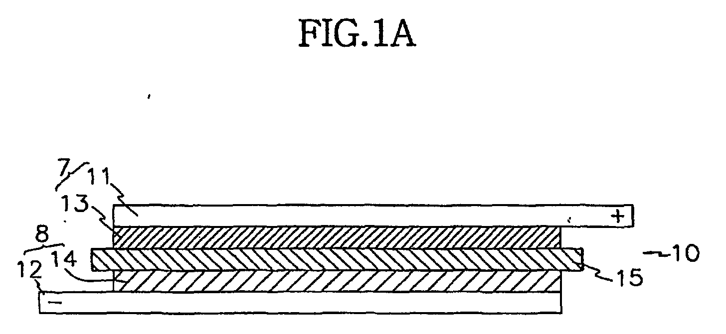
The most typical cell structure is illustrated in Fig. 1a, wherein a layered
structure of a positive electrode, an negative electrode, and a separator layer is
cut into a regular shape and size, and then stacked to form a full cell 10. In
the present invention, the full cell 10 of such a structure is treated as a unit cell
which constitutes a battery. Exemplarily, in a lithium rechargeable cell, the
positive active material 14 mainly comprises lithium intercalation materials such
as lithium manganese oxide, lithium cobalt oxide, lithium nickel oxide, or a
complex oxide formed from a combination of the aforesaid oxides, said positive
active material being bonded to the positive current collector 12, that is, a foil
prepared from aluminum, nickel, or a combination thereof, to form a positive
electrode 7. Also the negative active material 13 mainly comprises lithium
metal or lithium alloy, and lithium intercalation materials such as carbon,
petroleum coke, activated carbon, graphite, or other carbons, said negative
electrode material 13 being bonded to an negative current collector 11, that is,
a foil prepared from copper, gold, nickel, copper alloy, or a combination thereof,
to form an negative electrode 8.
The separator layer 15 is a multi-component film comprising a polymer
support layer film and a gellable polymer which are united with each other
without an interface between them, as described above.
The unit structure of the full cell 10 shown in Fig. 1a is composed of a
positive electrode 7, a separator layer 15, and an negative electrode 8,
sequentially. The separator layer 15 is located at the center of the cell. A
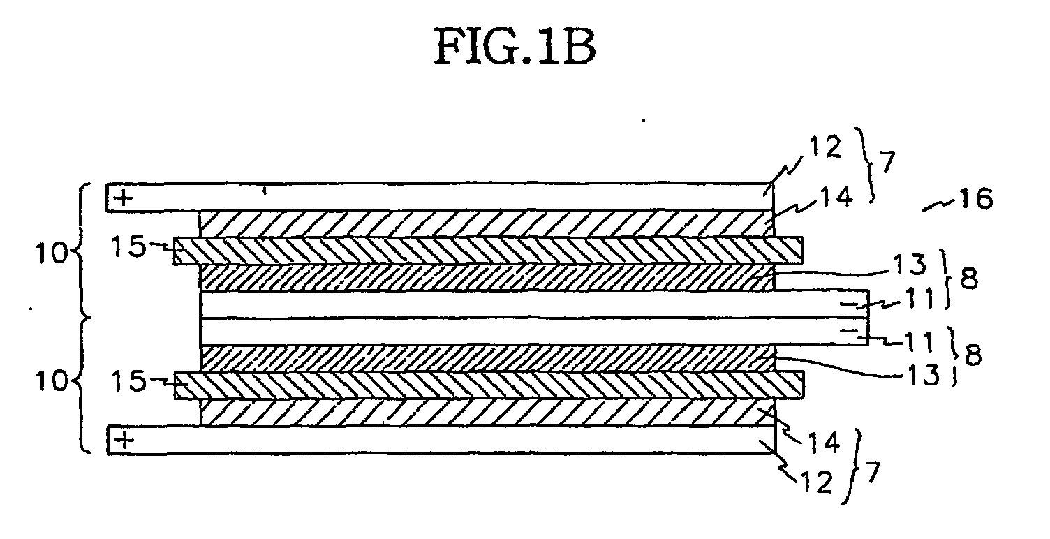
plurality of these unit cells can be stacked as shown in Fig. 1b to prepare a
battery with practical capacity.
The stacked cell 16 shown in Fig. 1b has only two unit cells stacked as
(10)/(10), but as many cells as desired can be stacked. The number of unit
cells to be stacked is designed and determined according to the desired
capacity of the battery. In a stacked cell 16 structure, the electrodes overlap
between the unit cells. If many units of cells are stacked, the number of
overlapping electrodes will also increase. As a result, space utilization will
decrease. Coating and using only a single side of the current collector during
the preparation of the electrodes causes such a problem.
The present invention provides a way to make more efficient use of the
space when multiple unit cells are overlapped, that is, it seeks to avoid
overlapping current collector plates by using a structure with identical active
material coated on both sides of the current collectors. If a full cell is prepared
using electrodes coated with electrode materials on both sides, a new unit cell
having such a structure as the full cell 17 of Fig. 2a comes into existence.
A stacked cell 18 as in Fig. 2b is prepared by stacking two full cells 17
as a unit cell and inserting a polymer separator layer such as the aforesaid
separator layer 15 or the separator film 19 therebetween. Such a structure
becomes very efficient because the outer active coating material not used
within a unit cell is shared with the opposite electrode active coating material of
an adjacent unit cell, forming a new full cell. This structure becomes more
effective as more unit cells are stacked. The electrode materials of the
outermost negative active material 13 and positive active material 14 of the
stacked cell 18, however, are not shared or used because the current collectors
are used as foils. The proportion taken up by the unused material decreases
as the stacks increase in unit cells. Because the number of unit cells is large
considering the thickness of the unit cell and the thickness of the battery that is
practically used, such a cell structure is sufficiently effective.
As shown in Fig. 3, three cells are stacked, which is considered as the
most effective structure upon considering all the above factors. It has the
minimum number of stacked unit cells. By stacking full cell structures 17' and
17" each having one electrode coated on both sides and the other electrode
coated on a single side on either side of the full cell 17, a new stacked cell 20 is
produced with a structure of 17'/17/17".
Thus, the unused portion of the outer active electrode material
appearing in the stacked cell 18 of Fig. 2b is eliminated. To achieve capacity
for a practical use, a plurality of layers is stacked such as
(17')/(17)/(17)... (17)/(17"). Thus, the more cell is stacked, the less different in
terms of space utilization efficiency of the stacked cell 20 from that of the
stacked cell 18 which has a structure of (17)/(17)/(17)... (17)/(17). The stacked
cell 20 structure, however, may be very effective for a thin layer card-type
battery.
The overlapping middle electrode plate of the stacked cell 16 structure
as shown in Fig. 1b degrades the efficiency of the cell as discussed above.
Therefore, an efficient structure unifying the overlapping electrodes between
the cells themselves can be treated as a new unit cell. The cell 21 shown in
Fig. 4a is such a new unit cell, being a bicell structure having a polarity at the
middle and an opposite polarity at both sides.
A cell having high space utilization can be made by stacking such bicell
units as the (21)/(21) structure shown in the stacked bicell 22 of Fig. 4b.
Alternatively, more layers of such units can be stacked to form a battery. In
this embodiment, however, overlapping electrodes between the bicells also
appear as in the case of the stacking cell 16 of Fig. 1b where full cells 10 of Fig.
1a are stacked. The details are the same as those of the stacking cell 16
structure, and the space utilization problem also exists, because the negative
current collector is coated on both sides but the positive current collector is
coated on a single side as can be seen in the bicell 21 of Fig. 4a. Although
the overlapping of the stacked cell 22 of Fig. 4b is less frequent compared to
the stacked cell 16 of Fig. 1b, the space utilization is nevertheless reduced.
The present invention provides a way to use the cell structure in a more
space-efficient manner compared to the case where a bicell is used as a unit
cell to be multiply stacked. That is, the present invention provides a method of
avoiding the overlapping of the current collectors by using current collectors
coated with identical active material on each side. To such end, two types of
bicells 23 and 24 are defined, which use electrodes with both sides coated as
shown in Fig. 5a and 5b. The bicell 23 in Fig. 5a places the negative electrode
at the center and the positive electrodes at the outer sides, whereas the bicell
24 of Fig. 5b places the positive electrode at the center and the negative
electrodes at the outer sides.
When the bicells are stacked in a (23)/(24) structure as in stacked cell
25 of Fig. 6 and the aforementioned polymer separator layer such as the
separator layer 15 or separator film 19 are inserted between the bicells, the
outer active coating material not used within a bicell is shared with an opposite
electrode active coating material of an adjacent bicell, forming a new full cell,
which is a very efficient structure. Such a cell can also be stacked into
multiple layers. In this case, if the separator films 19 are interposed between
the cells, and the bicells are alternately stacked as in
(23)/(24)/(23)/(24)/... (23)/(24)/(23), the polarity of the battery is naturally formed
without discrepancy. The outermost-stacked bicell of the battery can be either
bicell 23 or bicell 24, the only difference being whether the unused electrode
material is an negative electrode or a positive electrode. The proportion of
such unused electrodes decreases as the number of cells increases and it has
little influence on a battery with a practical thickness.
Fig. 7 shows a stacked cell 26 where the bicell is a basic unit and all
the above factors are considered to make an efficient structure. In this
drawing, only three bicells are stacked. When the primes (') denote structures
where only one out of two outer electrodes of the bicell is left as the foil, there is
no portion of active electrode material that is not used when the bicells are
stacked to a form of (24')/(23)/(24') as shown in stacked cell 26 of Fig. 7.
Variations in structure such as (23')/(24)/(23'), along with other combinations
are also possible. As explained above, when the bicells are stacked in
multiple layers as (24')/(23)/(24)/(23)..../(24)/(23)/(24'), there will be less
difference in space utilization efficiency compared to
(24)/(23)/(24)/(23).../(24)/(23)/(24) shown in the stacked cell 25 of Fig. 6 as
layers increase. In a thin layer card-type battery, however, the structure of
stacked cell 26 of Fig. 7 is effective.
According to the present invention, the electrochemical element
comprises a full cells or bicells as basic units which are multiply-stacked, and a
separator layer or a separator film of a polymer electrolyte interposed between
the stacked cells, wherein the separator is a multi-component composite film
comprising a polymer support layer film and a gellable polymer that are united
with each other without an interface between them. The conventional multi-component
composite film, which is used as a polymer electrolyte, is prepared
by coating a polymer film having pores of regular size with the gellable polymer
layer. In contrast, a multi-component composite film of the present invention is
prepared by coating a common polymer film with a gellable polymer material,
forming gellable polymer layers on a common polymer film having no pores,
and stretching and thermal setting, and the resultant film is used for a polymer
electrolyte. The polymer electrolyte system for electrochemical elements
using the multi-component is prepared by impregnating the composite film with
an aqueous electrolyte. In addition, in order to improve ion conductivity, the
polymer electrolyte system may use a simple polymer or a polymer-salt
complex produced from a coordinate bond of the polymer and a salt.
Hereinafter, the formation of the multi-component composite film will be
described.
The support layer film is preferably prepared by blending or laminating
at least one polymer selected from the group consisting of high-density
polyethylene, low-density polyethylene, linear low-density polyethylene,
polypropylene, high crystalline polypropylene, polyethylene-propylene
copolymer, polyethylene-butylene copolymer, polyethylene-hexene copolymer,
polyethylene-octene copolymer, polystyrene-butylene-styrene copolymer,
polystyrene-ethylene-butylene-styrene copolymer, polystyrene, polyphenylene
oxide, polysulfone, polycarbonate, polyester, polyamide, polyamide,
polyurethane, polyacrylate, polyvinylidene chloride, polyvinylidene fluoride,
polysiloxane, polyolefin ionomer, polymethyl pentene, hydrogenated
oligocyclopentadiene (HOCP), and a copolymer thereof, or a derivative thereof.
The high crystalline polypropylene preferably has at least one
characteristic selected from the group consisting of a density equal to or greater
than 0.905 g/cc, a melting point equal to or higher than 125°C, crystallinity
equal to or greater than 50%, isotacticity (or pentad ratio) equal to or greater
than 96%, and an atactic ratio of less than 5%.
The material of the gellable polymer layer may be selected according to
use of the multi-component composite film, and the gellable polymer is
generally at least one selected from the group consisting of polyvinylidene
fluoride, polyvinylidene fluoride-chlorotrifluoroethylene copolymer,
polyvinylidene fluoride-hexafluoropropylene copolymer, polyethylene oxide,
polybutylene oxide, polyurethane, polyacrylonitrile, polyacrylate, polymethyl
methacrylate, polyacrylic acid, polyamide, polyacrylamide, polyvinyl acetate,
polyvinylpyrrolidone, polytetraethylene glycol diacrylate, polysulfone,
polyphenylene oxide, polycarbonate chloride, polysiloxane, polyolefin ionomer,
and a copolymer thereof, or a derivative thereof.
The gellable polymer layer preferably comprises a polymer-lithium salt
complex so that an ion transference number of the gellable polymer layer
increases by anion fixation. The gellable polymer layer may further comprise
at least one selected from the group consisting of LiSCN, LiClO4, LiCF3SO3,
LiAsF6, LiN(CF3SO2)2, and LiBF4, each having a lithium lattice energy greater
than their dissolution energy, which is in accordance with the coordinate bond
of an electron-donating element and a lithium ion.
In addition, the gellable polymer layer may further include at least one
porous inorganic compound selected from the group consisting of SiO2, TiO2,
Al2O3, MgO, and B2O3.
Hereinafter, the preparation method of the multi-component composite
film will be described.
The multi-component composite film of the present invention is
prepared by coating the support layer film with the aforementioned gellable
polymer solution to form a geliable polymer layer on either or both sides of the
support layer film, and stretching it to form pores on the support layer film, so
that the support layer film and the gellable polymer layer are united together
without an interface between them. The stretching process forms pores in the
gellable polymer layer as well as the support layer film.
More specifically, the multi-component composite film is prepared
according to the method comprising the steps of:
The support layer film is preferably prepared by extruding the aforementioned
polymer in an extruder equipped with T-die or a tubular die, and annealing it in
a dry oven between room temperature and the greatest melting point of the
aforementioned polymers in order to increase its crystallinity and elastic
recovery.
In addition, an ion-beam irradiation step can be added to the
preparation steps of the multi-component composite film of the present
invention with a reactive gas in order to increase the interfacial adhesion
strength. The ion beam irradiation modifies the surface of the film, and it can
be performed before or after annealing, depending on the properties of the
multi-component composite film.
The ion-beam irradiation is performed by placing a support layer film in
a high vacuum chamber at 10-1 to 10-6 torr, injecting at least one ion source
selected from the group consisting of electrons, hydrogen, helium, oxygen,
nitrogen, carbon dioxide, air, fluoride, neon, argon, krypton, and N2O into an ion
gun, such that it has an energy ranging from 0.01 to 106 keV, and irradiating the
ion-beam on either or both sides of the support layer film with variation of an
ion-beam current. The irradiation amount of the ion beam preferably ranges
from 105 to 1020 ions/cm2. While the ion-beam is irradiating, at least one reactive
gas selected from the group consisting of helium, hydrogen, oxygen, nitrogen,
ammonia, carbon monoxide, carbon dioxide, tetrafluoro carbon, methane, and
N2O is added to the film at a flow rate of 0.5 to 20 mℓ/minute in order to modify
the surface of the film.
The gellable polymer layer is formed on either or both sides of the
support layer film with use of the gellable polymer solution. The gellable
polymer solution is prepared by dissolving the aforementioned polymer in a
solvent.
The solvent is at least one selected from the group consisting of 1-methyl-2-pyrrolidone
(NMP), acetone, ethanol, n-propanol, n-butanol, n-hexane,
cyclohexanol, acetic acid, ethyl acetate, diethyl ether, dimethyl formamide
(DMF), dimethylacetamide (DMAc), dioxane, tetrahydrofuran (THE, dimethyl
sulfoxide (DMSO), cyclohexane, benzene, toluene, xylene, and water, or a
mixture thereof. The concentration and coating condition of the gellable
polymer solution can be controlled depending on the material used in
preparation of the multi-component composite film, and the concentration of the
gellable polymer solution preferably ranges from 0.01 to 90 wt%. The gellable
polymer solution can be prepared by adding the aforementioned lithium salt,
porous inorganic particles, or a mixture thereof to the solvent.
The gellable polymer layer is formed in two ways. First, the support
layer film is coated with the gellable polymer solution, and the support layer film
is dried under a preferred drying condition to form the gellable polymer layer.
Secondly, a release paper or a release film is coated with the gellable polymer
solution in order to form the polymer film on the release paper, the coated film
is dried under the suitable drying condition, the polymer film is desorbed from
the release paper, and the desorbed polymer film is heat-set on the support
layer film. The heat-set process is performed at room temperature to a melting
point of the support layer or the gellable polymer of the gellable polymer
solution.
In the coating process of the gellable polymer solution on the support
layer film or the release film, the coating is performed by various techniques
such as dip coating, roll coating, spray coating, spin coating, die coating, and
roll coating, and the coating technique is not limited in the coating process.
The thickness of the coated films can be controlled depending on a final use of
the multi-component composite film, and if the thickness of the support layer
film ranges from 1 to 50 µm, the thickness of the gellable polymer layer after
coating preferably ranges from 0.01 to 25 µm.
The coating step can be performed either before or after, or both before
and after the annealing step, and the ion-beam irradiation process can be
performed with a reactive gas before the coating process, depending on the
properties of the multi-component composite film.
The drying process of the coated gellable polymer solution is preferably
performed under a gas atmosphere using at least one selected from the group
consisting of nitrogen, oxygen, carbon dioxide, and air, at a relative humidity of
1 to 100%.
Pores are formed on the heat-gellable polymer layer on either or both
sides of the support layer film, after the gellable polymer layer is formed on
either or both sides of the support layer film.
In general, pores are formed on a polymer film by phase transition or a
dry process. For example, pores can be formed through phase transition by
preparation of a polymer solution, and phase transition between the polymer
and the solvent with a suitable use of temperature or a non-solvent, and the
properties of the prepared film are affected by the phase-transition conditions.
As another example, pores can be formed through a dry process by orientation
of the crystalline region of the polymer in a certain direction, low-temperature-stretching
it, and rupturing the amorphous region which is relatively soft
compared to its crystalline region, wherein the properties of the prepared film
are affected by the orientation in the crystalline region and the degree of the
orientation.
In the present invention, the stretching process is performed after
forming the gellable polymer layer on either or both sides of the support layer
film. There are differences between the pore size and distribution of the
support layer film and those of the gellable polymer layer. Pores are formed
on the support layer by the dry process, wherein the crystalline structure of a
precursor is oriented in a certain direction in preparation of a precursor film, and
the oriented precursor film is stretched, thereby forming pores. On the other
hand, pores are formed on the gellable polymer layer by both the phase
transition and dry processes, wherein micro-pores or micro-cracks of the
gellable polymer layer are formed by phase transition between the gellable
polymer and the solvent, and the pore size or the micro-crack size increases
due to the stretching process. In particular, the phase transition condition
causes the gellable polymer layer to have various types of structure such as a
dense structure or a structure having micro-pores or micro-cracks before the
stretching process.
Therefore, the pore size and its distribution of the support layer film and
the gellable polymer layer are affected by the method of formation of the pores.
The stretching process includes low-temperature-stretching and high-temperature-stretching.
In the low-temperature-stretching process, the
gellable polymer layer is formed on either or both sides of the support layer film
in order to prepare a multi-layer, the multi-layer is mono-axially or bi-axially
stretched at a temperature ranging from 0 to 50°C with use of a roll or other
stretching machine in order to form micro-cracks, and the pores that are formed
on the gellable polymer increase.
In the high-temperature-stretching process, the micro-cracks that are
formed by the low-temperature-stretching are mono-axially or bi-axially
stretched with use of a roll or other stretching machine at between 50°C and a
melting point of the gellable polymer in order to form pores having a desired
size, so the mechanical properties of the film are brought about by the high-temperature
stretching.
The multi-film that is low-temperature-stretched and high-temperature-stretched
is heat-set. The heat-set processing is performed at a temperature
ranging from 50°C to a melting point of the support layer or the gellable
polymer layer under tension for 10 seconds to an hour, and the multi-component
composite film comprising the support layer film and gellable
polymer layer is thereby finally prepared.
The multi-component composite film of the present invention has an
improved interfacial adhesion strength between the support layer and the
gellable polymer layer due to inter-diffusion between the polymer chains of the
support layer and the gellable polymer layer after the high-temperature-stretching
and the heat-setting, and the interface between the support layer film
and the gellable polymer layer is not well-defined because the support layer film
and the gellable polymer layer are united together. In particular, when the ion-beam
irradiation on the support layer is performed with the reactive gas, the
interfacial adhesion strength between them improves further.
The multi-component composite film, after the high-temperature-stretching
and heat-setting, comprises a support layer film having a pore size
ranging from 0.001 to 10 µm with a thickness ranging from 1 to 50 µm, and a
porous gellable polymer layer having a pore size of 10 µm at most with a
thickness ranging from 0.01 to 25 µm, and the film of the present invention is
preferably applied to a polymer electrolyte system or an electrochemical
element.
Some steps of the method according to the present invention may be
skipped and steps may also be added depending upon the final use of the
multi-component composite film, and the sequence of each of the steps may be
changed.
Fig. 8 shows a cross-sectional view of an exemplary multi-component
composite film of the present invention wherein gellable polymer layers 42 are
located on the both side of a support layer film 41. It is also shown that the
interface 43 between the support layer film 41 and the gellable polymer layer 42
is not well-defined after stretching and heat-setting. The multi-component
composite film comprising a united support layer film and a gellable polymer
layer without an interface between them has good ionic conductivity and
electrochemical stability.
Accordingly, it is preferable to use the multi-component complex film for
one or more of the separator layers of a full cell or a bicell, or for the separator
film interposed between each stacked cell.
According to the present invention, since the electrochemical element
comprising stacked cells uses the multi-component complex film as. the
separator layer or the separator film, the resultant polymer electrolyte system
comprises:
wherein the support layer film of a) i) and the gellable polymer layer
of a) ii) are united together without an interface between them; and
b) a liquid electrolyte comprising i) a salt represented by Formula 1; and
ii) an organic solvent:
Formula 1
A+ B-
wherein A
+ is at least one selected from the group consisting of an
alkali metallic cation and a derivative thereof, and B
- is at least one selected
from the group consisting of PF
6 -, BF
4 -, Cl
-, Br
-, I
-, AsF
6 -, CH
3CO
2 -, CF
3SO
3 -,
N(CH
3SO
2)
2 -, and C(CH
3SO
2)
3 -.
The multi-component composite film of a) is a polymer, it can be used
for a separator and a solid electrolyte, and its air permeability ranges from 100
to 20,000 sec/100cc.
The liquid electrolyte of b) fills up the pores of the support layer film,
and the gellable polymer layer is swelled and gellated when the liquid
electrolyte of b) meets the multi-component composite film of a). In order to
increase the ionic conductivity of the liquid electrolyte, it is preferable that the
thickness of the gellable polymer layer is thinner than that of the support film.
The thin thickness of the gellable polymer brings low impedance that is
influenced by the thickness of the polymer electrolyte.
The liquid electrolyte of b) comprises a salt represented by Formula 1
that is dissolved and dissociated in an organic solvent of b) ii).
It is preferable that the organic solvent of b) ii) is at least one selected
from the group consisting of propylene carbonate (PC), ethylene carbonate
(EC), diethyl carbonate (DEC), dimethyl carbonate (DMC), dipropyl carbonate
(DPC), dimethyl sulfoxide, acetonitrile, dimethoxyethane, diethoxy ethane,
tetrahydrofuran, N-methyl-2-pyrrolidone (NMP), and ethyl methyl carbonate
(EMC).
The battery structure provided in the present invention is very effective
for a prismatic battery. Generally, liquid electrolyte is injected during
packaging. For such a purpose, an aluminum prismatic can or an aluminum-laminated
film can be used as a container. Unlike a jellyroll of a lithium ion
battery, the constituents of the battery according to the present invention have
a form coinciding with the form of the quadrilateral container so that there will
be no unused space within the container. Therefore, the energy density of the
battery can be greatly increased to implement a highly integrated battery having
maximized space efficiency of active materials.
The electrochemical element of the present invention can be applied to
various fields such as supercapacitors, ultracapacitors, primary batteries,
secondary batteries, fuel cells, sensors, electrolysis devices, electrochemical
reactors, etc, in addition to lithium secondary batteries.
The present invention will be explained in detail with reference to the
examples. These examples, however, should not in any sense be interpreted
as limiting the scope of the present invention.
[Examples]
Example 1
Preparing a stacked cell where a full cell is a basic unit
(Preparing positive electrodes)
LiCoO2, carbon black, and PVDF, of which the weight ratio was 95: 2.5:
2.5, were dispersed in 1-methyl-2-pyrrolidone (NMP) in order to prepare a slurry.
The slurry was then coated on aluminum foil on both sides of the aluminum foil.
After sufficiently drying at 130 °C; the positive electrodes were prepared by
pressing. The thickness of the positive electrode was 115 µm.
(Preparing an negative electrode)
Graphite: acetylene black: PVDF, of which the weight ratio was 93: 1: 6,
were dispersed in NMP in order to prepare a slurry The slurry was then
coated on a copper foil on both sides of the copper. After sufficiently drying at
130 °C, the negative electrodes were prepared by pressing. The thickness of
the negative electrode was 120 µm.
(Preparing a multi-component composite film)
A high crystalline polypropylene was used for a material of a precursor
film. It had a melt index of 2.0 g/10 minutes, a density of 0.91 g/cc, a melting
point of 166.5°C which was measured with DSC (Differential Scanning
Calorimeter), a crystallization temperature of 116.5°C, a crystallinity of 57%, an
isotacticity of 98% which was measured with C13 nuclear magnetic resonance
(NMR), and an atactic fraction of about 2% which was measured after being
dissolved in xylene. The precursor film was prepared from the high crystalline
polypropylene with use of a single screw extruder equipped with a T-die and a
take-up device. The extrusion temperature and cooling-roll temperature were
respectively 220 °C and 80 °C. The take-up speed was 20 m/min., and the
draw down rate (DDR) was 60.
The precursor film was annealed in a dry oven at 150°C for an hour.
After annealing, the solution that was dissolved in acetone was dip-coated
on both sides of the prepared precursor film. The coating was
performed under air while maintaining 60% relative humidity, and the acetone
was vaporized at the same condition of 60% relative humidity.
The coated precursor film was mono-axially low-temperature-stretched
to 50% of the stretching ratio based on the initial length of the film at room
temperature, and it was further mono-axially low-temperature-stretched to
100% of the stretching ratio based on the initial length of the film at 140°C.
After high-temperature-stretching, the high-temperature-stretched
precursor film was heat-set at 140°C under tension for 10 minutes, and it was
cooled in order to prepare a multi-component composite film. The properties
of the multi-component composite film were measured, and the properties are
shown in Table 1.
The air permeability and interfacial adhesion strength of the multi-component
composite film were respectively measured by JIS P8117 and JIS Z
0237, its pore size was measured with a scanning electron microscope, and
wet-out rate of an electrolyte was measured by measuring a time for wet-out of
2 cm
2 of the multi-component composite film in an electrolyte wherein ethylene
carbonate and dimethyl carbonate were mixed together in a volume ratio of 4:6.
| | Multi-Component Composite Film |
| Thickness (µm) | Support layer | 17 |
| Gellable polymer layer | 1 |
| Pore size (µm x µm) | Support layer | 0.3x0.1 |
| Gellable polymer layer | 0.8x0.3 |
| Air permeability (sec/100 cc) | 520 |
| Interfacial adhesion strength (gf) | 160 |
| Wet-out rate of an electrolyte (sec) | 9 |
The positive electrodes prepared in a manner mentioned above were
cut to the rectangular size of 2.9 cm x 4.3 cm, except for an area where a tab
was to be formed, and the negative electrodes prepared in a manner
mentioned above were cut to the rectangular size of 3.0 cm x 4.4 cm, except for
an area where a tab was to be formed.
The multi-component composite film prepared in a manner mentioned
above was cut to the size of 3.1 cm x 4.5 cm and interposed between the
negative electrodes and the positive electrodes, and by passing them through a
roll laminator of 100 °C to laminate each electrode and the separator layer, the
full cells were obtained.
(Stacking full cells)
The full cells 17', 17, and 17" were placed as in structure 20 of Fig. 3 in
the sequence of 17', 17, and 17" with the single-side coated electrodes at the
electrode current collector of the outermost side. The multi-component
composite films were cut to the size of 3.1 cm x 4.5 cm and inserted between
the adjoining portions of the full cells. Next, they were passed through a roll
laminator of 100 °C to laminate the full cells and the polymer films.
(Preparing a battery)
The prepared full cell stacked battery was placed within the aluminum
laminate package. Then the liquid electrolyte comprising a 1:2 weight ratio of
EC/EMC of 1 M LiPF6 was injected therein and it was packaged.
(Evaluating the performance of the battery)
Tests were carried out to evaluate the performance of the battery.
Firstly, the battery was charged and discharged under the condition of 0.2 C.
The battery was charged with the constant current until reaching 4.2V and then
charged to maintain the constant voltage of 4.2 V. The charge profile is shown
as 31 of Fig.9. The discharge was performed with the constant current to 3 V
and the profile thereof is shown as 32 of Fig. 9.
The other test for evaluating the performance of the battery is to
measure the change of capacity according to charge and discharge cycles
under the condition of 1 C. Fig 10 shows the small change in capacity from the
initial capacity. It is therefore understood that the battery can be provided with
good cycle characteristics by improving the adhesion of the interface of the
polymer electrolyte.
Example 2
Preparing a stacked cell where a bicell is a basic unit
(Preparing a positive electrode)
Each positive electrode was prepared according to the same method as
in the above Example 1.
A positive electrode of the bicell that was to be placed in the inner side
was prepared by coating the slurry on both sides of aluminum foil. That is,
the positive electrode has a positive active material coated on both sides of the
aluminum positive current collector. The thickness of the positive electrodes
was 140 µm.
(Preparing an negative electrode)
Each negative electrode was prepared was prepared according to the
same method as in the above Example 1.
Negative electrodes that were to be placed in the outermost sides of
the outermost full cells were prepared by coating the slurry and on both sides of
copper negative current collectors, and negative electrodes that were to be
placed in the inner side were prepared by coating the slurry on both sides of
copper negative current collectors. In this case, the negative electrode has an
negative active material coated on both sides of the copper negative current
collector. The thickness of the negative electrodes was 135 µm.
(Preparing a multi-component composite film for a separator film and a
separator layer)
The separator layers, separator films, and polymer film for polymer
electrolyte were prepared in a manner identical to Example 1.
(Preparing bicells to be placed in the inner side)
Positive electrodes having the aforesaid positive active material coated
on both sides of a positive current collector were cut to the rectangular size of
2.9 cm x 4.3 cm, except for an area where a tab was to be formed. An
negative electrode having an negative active material coated on both sides of
an negative current collector was cut to the rectangular size of 3.0 cm x 4.4 cm,
except for an area where a tab was to be formed.
The bicell 23 of Fig. 5a was prepared by placing a both-side coated
negative electrode in the middle and the both-side coated positive electrodes at
the outer sides, cutting multi-component composite films prepared in a manner
mentioned above to the size of 3.1 cm x 4.5 cm, interposing the above films
between the negative electrode and the positive electrodes, and passing it
through a roll laminator of 100 °C to laminate the electrodes and the separator
layers.
Another bicell, that is, the bicell 24 of Fig. 5b was prepared by placing a
both-side coated positive electrode in the middle and both-side coated negative
electrodes at the outer sides, cutting multi-component composite films prepared
in a manner mentioned above to the size of 3.1 cm x 4.5 cm, interposing the
above films between the negative electrodes and the positive electrode, and
passing it through a roll laminator of 100 °C to laminate the electrodes and the
separator layers.
(Preparing bicells to be placed in the outermost side)
The full cells 24' of Fig. 7 were each prepared by cutting negative
electrodes having negative active material coated on a single side of the
current collectors and an negative electrode having negative active material
coated on both sides of the current collector to the rectangular size of 2.9 cm x
4.3 cm, except for an area where a tab was to be formed; cutting a positive
electrode having positive active material coated on both sides of the positive
current collector to the rectangular size of 3.0 cm x 4.4 cm, except for an area
where a tab was to be formed; placing a single-side coated negative electrode,
a both-side coated positive electrode, and a both-side coated negative
electrode together in that order; cutting multi-component composite films
prepared in a manner mentioned above to the size of 3.1 cm x 4.5 cm;
interposing the above films between the negative electrodes and the positive
electrode; and passing it through a roll laminator of 100 °C to laminate the
electrodes and the separator layers.
(Stacking bicells)
The bicells 23 and 24' were placed as in structure 26 of Fig. 7 in the
sequence of 24', 23, and 24' with the single-side coated negative electrode
electrodes at the outermost sides. The multi-component composite films were
cut to the size of 3.1 cm x 4.5 cm and inserted between the adjoining portions
of the bicells. Next, they were passed through a roll laminator of 100 °C to
laminate the bicells and the polymer films.
(Preparing a battery)
The prepared stacked bicell battery was placed within an aluminum
laminate package. Then a liquid electrolyte comprising a 1:2 weight ratio of
EC/EMC of 1 M LiPF6 was injected therein and it was packaged.
The electrochemical element according to the present invention
multiply-stacked with full cells or bicells as a unit cell is easy to manufacture,
has a structure which uses the space available efficiently, and particularly it can
maximize the content of the active electrode material so that a highly integrated
battery can be implemented. The multi-component composite film interposed
between each stacked cell and used to separate layers of the present invention
has good electrochemical stability, adhesion to an electrode, wet-out rate of an
electrolyte, and stability, and even though extraction or removal processes of a
plasticizer are not performed, it has both good ionic conductivity and
mechanical properties, such that the film of the present invention can be used
in a polymer electrolyte system with electrochemical elements, and as a
separator.
While the present invention has been described in detail with reference
to the preferred embodiments, those skilled in the art will appreciate that
various modifications and substitutions can be made thereto without departing
from the spirit and scope of the present invention as set forth in the appended
claims.