EP1293845A1 - Composite blade for assisting complete transfer of a toner image from a photosensitive surface - Google Patents
Composite blade for assisting complete transfer of a toner image from a photosensitive surface Download PDFInfo
- Publication number
- EP1293845A1 EP1293845A1 EP02255901A EP02255901A EP1293845A1 EP 1293845 A1 EP1293845 A1 EP 1293845A1 EP 02255901 A EP02255901 A EP 02255901A EP 02255901 A EP02255901 A EP 02255901A EP 1293845 A1 EP1293845 A1 EP 1293845A1
- Authority
- EP
- European Patent Office
- Prior art keywords
- sheet
- blade
- transfer
- image
- layers
- Prior art date
- Legal status (The legal status is an assumption and is not a legal conclusion. Google has not performed a legal analysis and makes no representation as to the accuracy of the status listed.)
- Granted
Links
- 239000002131 composite material Substances 0.000 title claims description 10
- 229920000728 polyester Polymers 0.000 claims abstract description 18
- 239000004705 High-molecular-weight polyethylene Substances 0.000 claims abstract description 6
- 239000000463 material Substances 0.000 claims description 24
- 239000011248 coating agent Substances 0.000 claims description 5
- 238000000576 coating method Methods 0.000 claims description 5
- 238000005452 bending Methods 0.000 abstract description 9
- 230000000153 supplemental effect Effects 0.000 abstract description 2
- 108091008695 photoreceptors Proteins 0.000 description 33
- 239000002245 particle Substances 0.000 description 8
- 239000000843 powder Substances 0.000 description 8
- 238000003384 imaging method Methods 0.000 description 6
- 238000000034 method Methods 0.000 description 5
- 230000007547 defect Effects 0.000 description 4
- 238000000926 separation method Methods 0.000 description 3
- 238000004140 cleaning Methods 0.000 description 2
- 239000008187 granular material Substances 0.000 description 2
- 230000009191 jumping Effects 0.000 description 2
- 239000000758 substrate Substances 0.000 description 2
- 239000004809 Teflon Substances 0.000 description 1
- 229920006362 Teflon® Polymers 0.000 description 1
- 229920010741 Ultra High Molecular Weight Polyethylene (UHMWPE) Polymers 0.000 description 1
- 239000000853 adhesive Substances 0.000 description 1
- 230000001070 adhesive effect Effects 0.000 description 1
- 238000003491 array Methods 0.000 description 1
- 239000011324 bead Substances 0.000 description 1
- 230000015556 catabolic process Effects 0.000 description 1
- 238000012217 deletion Methods 0.000 description 1
- 230000037430 deletion Effects 0.000 description 1
- 238000007599 discharging Methods 0.000 description 1
- 239000006185 dispersion Substances 0.000 description 1
- 150000002500 ions Chemical class 0.000 description 1
- 239000011159 matrix material Substances 0.000 description 1
- 239000004033 plastic Substances 0.000 description 1
- 229920003023 plastic Polymers 0.000 description 1
- 229920001343 polytetrafluoroethylene Polymers 0.000 description 1
- 239000004810 polytetrafluoroethylene Substances 0.000 description 1
- 230000000644 propagated effect Effects 0.000 description 1
- 239000007787 solid Substances 0.000 description 1
- 239000007921 spray Substances 0.000 description 1
- 230000007704 transition Effects 0.000 description 1
- 230000032258 transport Effects 0.000 description 1
- 238000011144 upstream manufacturing Methods 0.000 description 1
- 239000002699 waste material Substances 0.000 description 1
Images



Classifications
-
- G—PHYSICS
- G03—PHOTOGRAPHY; CINEMATOGRAPHY; ANALOGOUS TECHNIQUES USING WAVES OTHER THAN OPTICAL WAVES; ELECTROGRAPHY; HOLOGRAPHY
- G03G—ELECTROGRAPHY; ELECTROPHOTOGRAPHY; MAGNETOGRAPHY
- G03G15/00—Apparatus for electrographic processes using a charge pattern
- G03G15/14—Apparatus for electrographic processes using a charge pattern for transferring a pattern to a second base
- G03G15/16—Apparatus for electrographic processes using a charge pattern for transferring a pattern to a second base of a toner pattern, e.g. a powder pattern, e.g. magnetic transfer
- G03G15/163—Apparatus for electrographic processes using a charge pattern for transferring a pattern to a second base of a toner pattern, e.g. a powder pattern, e.g. magnetic transfer using the force produced by an electrostatic transfer field formed between the second base and the electrographic recording member, e.g. transfer through an air gap
- G03G15/1635—Apparatus for electrographic processes using a charge pattern for transferring a pattern to a second base of a toner pattern, e.g. a powder pattern, e.g. magnetic transfer using the force produced by an electrostatic transfer field formed between the second base and the electrographic recording member, e.g. transfer through an air gap the field being produced by laying down an electrostatic charge behind the base or the recording member, e.g. by a corona device
- G03G15/165—Arrangements for supporting or transporting the second base in the transfer area, e.g. guides
-
- G—PHYSICS
- G03—PHOTOGRAPHY; CINEMATOGRAPHY; ANALOGOUS TECHNIQUES USING WAVES OTHER THAN OPTICAL WAVES; ELECTROGRAPHY; HOLOGRAPHY
- G03G—ELECTROGRAPHY; ELECTROPHOTOGRAPHY; MAGNETOGRAPHY
- G03G2215/00—Apparatus for electrophotographic processes
- G03G2215/16—Transferring device, details
- G03G2215/1604—Main transfer electrode
- G03G2215/1609—Corotron
-
- G—PHYSICS
- G03—PHOTOGRAPHY; CINEMATOGRAPHY; ANALOGOUS TECHNIQUES USING WAVES OTHER THAN OPTICAL WAVES; ELECTROGRAPHY; HOLOGRAPHY
- G03G—ELECTROGRAPHY; ELECTROPHOTOGRAPHY; MAGNETOGRAPHY
- G03G2215/00—Apparatus for electrophotographic processes
- G03G2215/16—Transferring device, details
- G03G2215/1604—Main transfer electrode
- G03G2215/1628—Blade
Definitions
- This invention relates generally to an image transfer device and more particularly, concerns a composite transfer assist blade to contact a sheet in a transfer zone on a photoreceptive member to allow more complete transfer of the image developed thereon to the sheet.
- a photoconductive member is charged to a substantially uniform potential so as to sensitize the surface thereof.
- the charged portion of the photoconductive member is exposed to a light image of an original document being reproduced. Exposure of the charged photoconductive member selectively dissipates the charges thereon in the irradiated areas.
- the latent image is developed by bringing a developer material into contact therewith.
- the developer material comprises toner particles adhering triboelectrically to carrier granules.
- the toner particles are attracted from the carrier granules to the latent image forming a toner powder image on the photoconductive member.
- the toner powder image is then transferred from the photoconductive member to a copy sheet.
- the toner particles are heated to permanently affix the powder image to the copy sheet.
- the foregoing generally describes a typical black and white electrophotographic printing machine.
- an architecture which comprises a plurality of image forming stations.
- One example of the plural image forming station architecture utilizes an image-on-image (IOI) system in which the photoreceptive member is recharged, re-imaged and developed for each color separation.
- IIOI image-on-image
- This charging, imaging, developing and recharging, re-imaging and developing, all followed by transfer to paper is done in a single revolution of the photoreceptor in so-called single pass machines, while multi-pass architectures form each color separation with a single charge, image and develop, with separate transfer operations for each color.
- a composite transfer assist blade comprising a plurality of layers wherein at least one of said plurality of layers comprises a polyester material having a semiconductive coating thereon, a second one of said plurality of layers comprising a second polyester material bonded to said first polyester layer and a third one of said plurality of layers comprising a high molecular weight polyethylene material bonded to said second polyester material.
- an electrophotographic printing machine having a photoreceptive member and including a composite transfer assist blade, comprising a plurality of layers wherein at least one of said plurality of layers comprises a polyester material having a semiconductive coating thereon, a second one of said plurality of layers comprising a second polyester material bonded to said first polyester layer and a third one of said plurality of layers comprising a high molecular weight polyethylene material bonded to said second polyester material.
- This invention relates to printing system which is used to produce color output in a single pass of a photoreceptor belt. It will be understood, however, that a multi-pass color process system, a single or multiple pass highlight color system and a black and white printing system.
- the electrophotographic printing machine of the present invention uses a charge retentive surface in the form of an Active Matrix (AMAT) photoreceptor belt 10 supported for movement in the direction indicated by arrow 12, for advancing sequentially through the various xerographic process stations.
- the belt is entrained about a drive roller 14 and tension and steering rollers 16 and 18 respectively, roller 14 is operatively connected to a drive motor 20 for effecting movement of the belt through the xerographic stations.
- AMAT Active Matrix
- a portion of belt 10 passes through charging station A where a corona generating device, indicated generally by the reference numeral 22, charges the photoconductive surface of belt 10 to a relative high, substantially uniform, preferably negative potential.
- the charged portion of photoconductive surface is advanced through an imaging station B.
- the uniformly charged belt 10 is exposed to a laser based output scanning device 24 which causes the charge retentive surface to be discharged in accordance with the output from the scanning device.
- the scanning device is a laser Raster Output Scanner (ROS).
- ROS Raster Output Scanner
- the ROS could be replaced by other xerographic exposure devices such as LED arrays.
- the photoreceptor which is initially charged to a voltage V c , undergoes dark decay to a level V ddp equal to about -500 volts. When exposed at the exposure station B it is discharged to V image equal to about -50 volts. Thus after exposure, the photoreceptor contains a monopolar voltage profile of high and low voltages, the former corresponding to charged areas and the latter corresponding to discharged or image areas.
- developer structure indicated generally by the reference numeral 32 utilizing a hybrid jumping development (HJD) system
- the development roll better known as the donor roll
- the first field is the AC jumping field which is used for toner cloud generation.
- the second field is the DC development field which is used to control the amount of developed toner mass on the photoreceptor.
- the toner cloud causes charged toner particles 26 to be attracted to the electrostatic latent image. Appropriate developer biasing is accomplished via a power supply.
- This type of system is a non-contact type in which only toner particles (magenta, for example) are attracted to the latent image and there is no mechanical contact between the photoreceptor and a toner delivery device to disturb a previously developed, but unfixed, image.
- toner particles magenta, for example
- the developed but unfixed image is then transported past a second charging device 36 where the photoreceptor and previously developed toner image areas are recharged to a predetermined level.
- a second exposure/imaging is performed by imaging device 38 which comprises a laser based output structure and is utilized for selectively discharging the photoreceptor on toned areas and/or bare areas, pursuant to the image to be developed with the second color toner.
- the photoreceptor contains toned and untoned areas at relatively high voltage levels and toned and untoned areas at relatively low voltage levels. These low voltage areas represent image areas which are developed using discharged area development (DAD).
- DAD discharged area development
- a negatively charged, developer material 40 comprising color toner is employed.
- the toner which by way of example may be yellow, is contained in a developer housing structure 42 disposed at a second developer station D and is presented to the latent images on the photoreceptor by way of a second HSD developer system.
- a power supply (not shown) serves to electrically bias the developer structure to a level effective to develop the discharged image areas with negatively charged yellow toner particles 40.
- a negative pre-transfer dicorotron member 50 is provided to condition the toner for effective transfer to a substrate using positive corona discharge.
- a sheet of support material 52 is moved into contact with the toner images at transfer station G.
- the sheet of support material is advanced to transfer station G by a sheet feeding apparatus to the pre-transfer device of the present invention which directs the advancing sheet of support material into contact with photoconductive surface of belt 10 in a timed sequence so that the toner powder image developed thereon contacts the advancing sheet of support material at transfer station G.
- Transfer station G includes a transfer dicorotron 54 which sprays positive ions onto the backside of sheet 52. This attracts the negatively charged toner powder images from the belt 10 to sheet 52.
- a detack dicorotron 56 is provided for facilitating stripping of the sheets from the belt 10.
- Fusing station H includes a fuser assembly, indicated generally by the reference numeral 60, which permanently affixes the transferred powder image to sheet 52.
- fuser assembly 60 comprises a heated fuser roller 62 and a backup or pressure roller 64.
- Sheet 52 passes between fuser roller 62 and backup roller 64 with the toner powder image contacting fuser roller 62. In this manner, the toner powder images are permanently affixed to sheet 52 after it is allowed to cool.
- a chute guides the advancing sheets 52 to a catch tray, not shown, for subsequent removal from the printing machine by the operator.
- the residual toner particles carried by the non-image areas on the photoconductive surface are removed therefrom. These particles are removed at cleaning station I using a cleaning brush structure contained in a housing 66.
- the device transports/transitions a sheet with precision to the photoreceptor belt. It minimizes variations in impact and tangency contact locations prior/during transfer and yet is flexible enough to allow sheet delivery at minimal drive and contact forces.
- the low contact forces eliminate sheet marking on sensitive paper substrates. It also accurately controls sheet placement during conditions of extreme curl (nominally +/-100mm radii for 34gsm weight and +/-250mm radii for 271 gsm weight paper) with consistent photoreceptor (P/R) belt contacts and tangencies.
- the lead edge 152 of the paper 52 exits nip 160 formed by rolls 158 and 156, and enters the lower pre transfer baffle area 170 (see figure 2).
- This area 170 provides guides 172, 174, 181 to guide the paper during sheet transfer to the photoreceptor 10.
- Guide 182 is an idler roll which in combination with the control point 180 of guide 181 provide tight control of the sheet and minimize the sheet variations during initial and tangential photoreceptor contact.
- guides 180 and 182 induce reverse stress on the sheet allowing for accurate placement of the sheet lead edge 152 on the photoreceptor 10.
- the sheet 52 continues its motion until the sheet contacts the photoreceptor 10. At this point the gap between roll 182 and contact point 190, serves as a gate or control point. At contact point 190, the sheet angle should be greater than 15° but less than 25°. This angle is achieved to reduce sheet contact forces with the photoreceptor 10. Roll 182 may also be spring loaded or otherwise biased to reduce the stress induced on heavier and stiffer paper when it attempts to bend and tack against the P/R belt 10.
- the device herein virtually eliminates the stalling problem of high stiffness paper at high contact angles by adding a roller at the high paper friction points. Now both high and low stiffness paper can be run at the same contact angle without stalling (paper contact angle on P/R belt 10 preferably less than 20°).
- the passive roll 182 in combination with the control point 180 of baffle 181 are strategically located to impart a "reverse” stress to the sheet 52 to act as a passive “decurler” (no moving parts). This dramatically minimizes the variability of the paper contact points on the photoreceptor.
- control points provide stability to the sheet prior to it entering the transfer zone and thus reducing the chances of paper smear, etc. (no paper disturbance upstream) and they provide only two contact points (tangent to the rolls) with the paper which also minimizes the drag force and thus required drive force as opposed to baffles that would provide an inconsistent number of contact points and a higher drag force on the paper.
- the trail edge ramp 183 guides the trail edge 153 of the sheet until it is almost in contact with the photoreceptor which has the benefit of increasing the beam length of the sheet which dramatically reduces the bending energy and subsequent forces which cause print defects due to trail edge flip.
- the pre-transfer device is further able to deliver the various weight sheets to the photoreceptor with a minimal impact and print defects due to sheet movement.
- the composite transfer assist blade overcomes the problems associated with a single component blade.
- a single component blade in order to be flexible enough to prevent image damage does not provide enough contact force to the back of the sheet to enable complete image transfer giving rise to transfer deletions and color shift. If a thick enough blade is used, the stress on the single blade material is too great.
- the blade is used to eliminate air gaps between the sheet and the photoreceptor because the presence of air gaps can cause air breakdown in the transfer field, thus causing transfer defects.
- the use of the multi layer composite blade 186 as illustrated in Figure 5 provides a blade that has the necessary contact pressure while maintaining a lower bending stress within each layer.
- the blade 186 is made up of a plastic bead or mounting portion 186 to which a first layer 188 of electrostatic dispersion material is bonded.
- This material can be polyester with a semiconductive coating to prevent a field build up on the blade surface facing the charge device 54.
- a field build up could lead to an image disturbance in the transfer step.
- the field could impart a tangential force on the toner pile and pull it sideways. This is called "dragout”.
- With a semi-conductive coating the current that hits the blade assembly is bled away, thereby preventing a field from building. The current bled away can go to ground (it works, but is a waste of energy) or can be returned to the power supply which can then compensate for the current it supplies to that charging device.
- a second layer 189 is then bonded to the first layer 188 only in the area of the mounting portion with adhesive 192 to allow the blade layers to flex independently, and is a polyester that is non-semiconductive. There are then bonded to the second layer 189 a third and in some instances a fourth layer of low friction surfaces for wear resistance material.
- These third and fourth layers are ultra-high molecular weight polyethylene (UHMWPE).
- UHMWPE ultra-high molecular weight polyethylene
- RTM Teflon
- the third 190 and fourth 191 layers do not extend for the full length (in the process direction) of the blade as shown in Fig. 5.
- These third 190 and fourth 191 layers add supplementary stiffness to the blade to assist in more complete transfer of the image.
- a transfer assist blade for an electrophotographic printing machine that provides the necessary stiffness to allow complete transfer of a toner image while avoiding excessive bending stress in the blade.
- the blade is made up of a semi-conductive polyester layer bonded to a non-semiconductive polyester layer.
- a third and fourth layer of high molecular weight polyethylene are bonded to the second layer. These third and fourth layers do not extend the full length of the blade to provide supplemental stiffness while avoiding excess bending stress.
Landscapes
- Physics & Mathematics (AREA)
- General Physics & Mathematics (AREA)
- Electrostatic Charge, Transfer And Separation In Electrography (AREA)
- Color Electrophotography (AREA)
Abstract
Description
- This invention relates generally to an image transfer device and more particularly, concerns a composite transfer assist blade to contact a sheet in a transfer zone on a photoreceptive member to allow more complete transfer of the image developed thereon to the sheet.
- In a typical electrophotographic printing process, a photoconductive member is charged to a substantially uniform potential so as to sensitize the surface thereof. The charged portion of the photoconductive member is exposed to a light image of an original document being reproduced. Exposure of the charged photoconductive member selectively dissipates the charges thereon in the irradiated areas. This records an electrostatic latent image on the photoconductive member corresponding to the informational areas contained within the original document. After the electrostatic latent image is recorded on the photoconductive member, the latent image is developed by bringing a developer material into contact therewith. Generally, the developer material comprises toner particles adhering triboelectrically to carrier granules. The toner particles are attracted from the carrier granules to the latent image forming a toner powder image on the photoconductive member. The toner powder image is then transferred from the photoconductive member to a copy sheet. The toner particles are heated to permanently affix the powder image to the copy sheet.
- The foregoing generally describes a typical black and white electrophotographic printing machine. With the advent of multicolor electrophotography, it is desirable to use an architecture which comprises a plurality of image forming stations. One example of the plural image forming station architecture utilizes an image-on-image (IOI) system in which the photoreceptive member is recharged, re-imaged and developed for each color separation. This charging, imaging, developing and recharging, re-imaging and developing, all followed by transfer to paper, is done in a single revolution of the photoreceptor in so-called single pass machines, while multi-pass architectures form each color separation with a single charge, image and develop, with separate transfer operations for each color.
- In single pass color machines it is desirable to cause as little disturbance to the photoreceptor as possible so that motion errors are not propagated along the belt to cause image quality and color separation registration problems. One area that has potential to cause such a disturbance is when a sheet is released from the guide after having been brought into contact with the photoreceptor for transfer of the developed image thereto. This disturbance which is often referred to as trail edge flip can cause image defects on the sheet due to the motion of the sheet during transfer caused by energy released due to the bending forces of the sheet. Particularly in machines which handle a large range of paper weights and sizes it is difficult to have a sheet guide which can properly position any weight and size sheet while not causing the sheet to oscillate after having come in contact with the photoreceptor.
- It is therefore desirable to have a pre-transfer sheet guide that can handle a wide variety of sheet weights and sizes while maintaining the capability to align and deliver the sheet to the photoreceptor with as little impact and sheet motion as possible.
- In accordance with one aspect of the present invention, there is provided a composite transfer assist blade, comprising a plurality of layers wherein at least one of said plurality of layers comprises a polyester material having a semiconductive coating thereon, a second one of said plurality of layers comprising a second polyester material bonded to said first polyester layer and a third one of said plurality of layers comprising a high molecular weight polyethylene material bonded to said second polyester material.
- In accordance with another aspect of the invention there is provided an electrophotographic printing machine having a photoreceptive member and including a composite transfer assist blade, comprising a plurality of layers wherein at least one of said plurality of layers comprises a polyester material having a semiconductive coating thereon, a second one of said plurality of layers comprising a second polyester material bonded to said first polyester layer and a third one of said plurality of layers comprising a high molecular weight polyethylene material bonded to said second polyester material.
- A particular embodiment in accordance with this invention will now be described with reference to the accompanying drawings; in which:-
- Figure 1 is a schematic elevational view of a full color image-on-image single-pass electrophotographic printing machine utilizing the device described herein; and
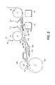
- Figure 2 is a side view illustrating the pre-transfer device relative to the Fig. 1 printing machine.
- Figure 3 is a side view illustrating the pre-transfer device baffle function relative to the Fig. 1 printing machine.
-
- This invention relates to printing system which is used to produce color output in a single pass of a photoreceptor belt. It will be understood, however, that a multi-pass color process system, a single or multiple pass highlight color system and a black and white printing system.
- Turning now to Figure 1, the electrophotographic printing machine of the present invention uses a charge retentive surface in the form of an Active Matrix (AMAT)
photoreceptor belt 10 supported for movement in the direction indicated byarrow 12, for advancing sequentially through the various xerographic process stations. The belt is entrained about adrive roller 14 and tension andsteering rollers roller 14 is operatively connected to adrive motor 20 for effecting movement of the belt through the xerographic stations. - With continued reference to Figure 1, a portion of
belt 10 passes through charging station A where a corona generating device, indicated generally by thereference numeral 22, charges the photoconductive surface ofbelt 10 to a relative high, substantially uniform, preferably negative potential. - Next, the charged portion of photoconductive surface is advanced through an imaging station B. At exposure station B, the uniformly
charged belt 10 is exposed to a laser basedoutput scanning device 24 which causes the charge retentive surface to be discharged in accordance with the output from the scanning device. Preferably the scanning device is a laser Raster Output Scanner (ROS). Alternatively, the ROS could be replaced by other xerographic exposure devices such as LED arrays. - The photoreceptor, which is initially charged to a voltage Vc, undergoes dark decay to a level Vddp equal to about -500 volts. When exposed at the exposure station B it is discharged to Vimage equal to about -50 volts. Thus after exposure, the photoreceptor contains a monopolar voltage profile of high and low voltages, the former corresponding to charged areas and the latter corresponding to discharged or image areas.
- At a first development station C, developer structure, indicated generally by the
reference numeral 32 utilizing a hybrid jumping development (HJD) system, the development roll, better known as the donor roll, is powered by two development fields (potentials across an air gap). The first field is the AC jumping field which is used for toner cloud generation. The second field is the DC development field which is used to control the amount of developed toner mass on the photoreceptor. The toner cloud causescharged toner particles 26 to be attracted to the electrostatic latent image. Appropriate developer biasing is accomplished via a power supply. This type of system is a non-contact type in which only toner particles (magenta, for example) are attracted to the latent image and there is no mechanical contact between the photoreceptor and a toner delivery device to disturb a previously developed, but unfixed, image. - The developed but unfixed image is then transported past a
second charging device 36 where the photoreceptor and previously developed toner image areas are recharged to a predetermined level. - A second exposure/imaging is performed by
imaging device 38 which comprises a laser based output structure and is utilized for selectively discharging the photoreceptor on toned areas and/or bare areas, pursuant to the image to be developed with the second color toner. At this point, the photoreceptor contains toned and untoned areas at relatively high voltage levels and toned and untoned areas at relatively low voltage levels. These low voltage areas represent image areas which are developed using discharged area development (DAD). To this end, a negatively charged,developer material 40 comprising color toner is employed. The toner, which by way of example may be yellow, is contained in adeveloper housing structure 42 disposed at a second developer station D and is presented to the latent images on the photoreceptor by way of a second HSD developer system. A power supply (not shown) serves to electrically bias the developer structure to a level effective to develop the discharged image areas with negatively chargedyellow toner particles 40. - The above procedure is repeated for a third image for a third suitable color toner such as cyan and for a fourth image and suitable color toner such as black. The exposure control scheme described below may be utilized for these subsequent imaging steps. In this manner a full color composite toner image is developed on the photoreceptor belt.
- To the extent to which some toner charge is totally neutralized, or the polarity reversed, thereby causing the composite image developed on the photoreceptor to consist of both positive and negative toner, a negative pre-transfer dicorotron member 50 is provided to condition the toner for effective transfer to a substrate using positive corona discharge.
- Subsequent to image development a sheet of
support material 52 is moved into contact with the toner images at transfer station G. The sheet of support material is advanced to transfer station G by a sheet feeding apparatus to the pre-transfer device of the present invention which directs the advancing sheet of support material into contact with photoconductive surface ofbelt 10 in a timed sequence so that the toner powder image developed thereon contacts the advancing sheet of support material at transfer station G. - Transfer station G includes a
transfer dicorotron 54 which sprays positive ions onto the backside ofsheet 52. This attracts the negatively charged toner powder images from thebelt 10 tosheet 52. Adetack dicorotron 56 is provided for facilitating stripping of the sheets from thebelt 10. - After transfer, the sheet continues to move, in the direction of
arrow 58, onto a conveyor (not shown) which advances the sheet to fusing station H. Fusing station H includes a fuser assembly, indicated generally by thereference numeral 60, which permanently affixes the transferred powder image tosheet 52. Preferably,fuser assembly 60 comprises a heatedfuser roller 62 and a backup orpressure roller 64.Sheet 52 passes betweenfuser roller 62 andbackup roller 64 with the toner powder image contactingfuser roller 62. In this manner, the toner powder images are permanently affixed tosheet 52 after it is allowed to cool. After fusing, a chute, not shown, guides the advancingsheets 52 to a catch tray, not shown, for subsequent removal from the printing machine by the operator. - After the sheet of support material is separated from photoconductive surface of
belt 10, the residual toner particles carried by the non-image areas on the photoconductive surface are removed therefrom. These particles are removed at cleaning station I using a cleaning brush structure contained in ahousing 66. - It is believed that the foregoing description is sufficient for the purposes of the present application to illustrate the general operation of a color printing machine.
- As shown in Fig. 2, the device transports/transitions a sheet with precision to the photoreceptor belt. It minimizes variations in impact and tangency contact locations prior/during transfer and yet is flexible enough to allow sheet delivery at minimal drive and contact forces. The low contact forces eliminate sheet marking on sensitive paper substrates. It also accurately controls sheet placement during conditions of extreme curl (nominally +/-100mm radii for 34gsm weight and +/-250mm radii for 271 gsm weight paper) with consistent photoreceptor (P/R) belt contacts and tangencies.
- As the energy that a sheet will generate due to bending is approximately inversely proportional to the cube of the beam length of the sheet it is important to provide the longest beam length possible to minimize the deflection energy will still providing precise control of a sheet being delivered to the photoreceptor. Additionally the sheet needs to maintain good contact with the photoreceptor to assure more complete image transfer.
- The
lead edge 152 of thepaper 52 exits nip 160 formed byrolls area 170, providesguides 172, 174, 181 to guide the paper during sheet transfer to thephotoreceptor 10. - The sheet continues its motion to
guides 181 and 182, where sheet contact is made on each guide.Guide 182 is an idler roll which in combination with thecontrol point 180 of guide 181 provide tight control of the sheet and minimize the sheet variations during initial and tangential photoreceptor contact. During conditions of sheet up/down curl, guides 180 and 182 induce reverse stress on the sheet allowing for accurate placement of thesheet lead edge 152 on thephotoreceptor 10. - The
sheet 52 continues its motion until the sheet contacts thephotoreceptor 10. At this point the gap betweenroll 182 andcontact point 190, serves as a gate or control point. Atcontact point 190, the sheet angle should be greater than 15° but less than 25°. This angle is achieved to reduce sheet contact forces with thephotoreceptor 10. Roll 182 may also be spring loaded or otherwise biased to reduce the stress induced on heavier and stiffer paper when it attempts to bend and tack against the P/R belt 10. - The
sheet 52 continues untilsheet tangency point 192 occurs on thephotoreceptor belt 10. A transfer assist blade contacts the back of the sheet to provide solid contact between the sheet and the photoreceptor to allow more complete transfer of the image. As the sheet progresses onto the photoreceptor it can be seen in Figure 3 that there are two components ofbeam length roll 182 andcontrol point 180 of baffle 181. As the sheet progresses even further as shown in Figure 4, the trail edge of the sheet is controlled byramp 183 to minimize the bending stress on the sheet. At this point the beam length as indicated byarrow 204 is considerably longer than it was in Figure 2 as the sheet is no longer contactingroll 182 and spans from the contact point of the transfer assist blade to the edge oframp 183. - The device herein virtually eliminates the stalling problem of high stiffness paper at high contact angles by adding a roller at the high paper friction points. Now both high and low stiffness paper can be run at the same contact angle without stalling (paper contact angle on P/
R belt 10 preferably less than 20°). - The
passive roll 182 in combination with thecontrol point 180 of baffle 181 are strategically located to impart a "reverse" stress to thesheet 52 to act as a passive "decurler" (no moving parts). This dramatically minimizes the variability of the paper contact points on the photoreceptor. - The control points provide stability to the sheet prior to it entering the transfer zone and thus reducing the chances of paper smear, etc. (no paper disturbance upstream) and they provide only two contact points (tangent to the rolls) with the paper which also minimizes the drag force and thus required drive force as opposed to baffles that would provide an inconsistent number of contact points and a higher drag force on the paper. Additionally, the
trail edge ramp 183 guides thetrail edge 153 of the sheet until it is almost in contact with the photoreceptor which has the benefit of increasing the beam length of the sheet which dramatically reduces the bending energy and subsequent forces which cause print defects due to trail edge flip. Thus, the pre-transfer device is further able to deliver the various weight sheets to the photoreceptor with a minimal impact and print defects due to sheet movement. - The composite transfer assist blade overcomes the problems associated with a single component blade. Typically a single component blade in order to be flexible enough to prevent image damage does not provide enough contact force to the back of the sheet to enable complete image transfer giving rise to transfer deletions and color shift. If a thick enough blade is used, the stress on the single blade material is too great. The blade is used to eliminate air gaps between the sheet and the photoreceptor because the presence of air gaps can cause air breakdown in the transfer field, thus causing transfer defects.
- The use of the multi layer
composite blade 186 as illustrated in Figure 5 provides a blade that has the necessary contact pressure while maintaining a lower bending stress within each layer. Theblade 186 is made up of a plastic bead or mountingportion 186 to which afirst layer 188 of electrostatic dispersion material is bonded. This material can be polyester with a semiconductive coating to prevent a field build up on the blade surface facing thecharge device 54. A field build up could lead to an image disturbance in the transfer step. The field could impart a tangential force on the toner pile and pull it sideways. This is called "dragout". With a semi-conductive coating, the current that hits the blade assembly is bled away, thereby preventing a field from building. The current bled away can go to ground (it works, but is a waste of energy) or can be returned to the power supply which can then compensate for the current it supplies to that charging device. - A
second layer 189 is then bonded to thefirst layer 188 only in the area of the mounting portion with adhesive 192 to allow the blade layers to flex independently, and is a polyester that is non-semiconductive. There are then bonded to the second layer 189 a third and in some instances a fourth layer of low friction surfaces for wear resistance material. These third and fourth layers are ultra-high molecular weight polyethylene (UHMWPE). Another candidate would be one from the Teflon (RTM) family (e.g. PTFE). The third 190 and fourth 191 layers do not extend for the full length (in the process direction) of the blade as shown in Fig. 5. These third 190 and fourth 191 layers add supplementary stiffness to the blade to assist in more complete transfer of the image. - In recapitulation, there is provided a transfer assist blade for an electrophotographic printing machine that provides the necessary stiffness to allow complete transfer of a toner image while avoiding excessive bending stress in the blade. The blade is made up of a semi-conductive polyester layer bonded to a non-semiconductive polyester layer. A third and fourth layer of high molecular weight polyethylene are bonded to the second layer. These third and fourth layers do not extend the full length of the blade to provide supplemental stiffness while avoiding excess bending stress.
Claims (5)
- A composite transfer assist blade, comprising a plurality of layers wherein at least one of said plurality of layers comprises a polyester material having a semiconductive coating thereon, a second one of said plurality of layers comprises a second polyester material bonded to said first polyester layer, and a third one of said plurality of layers comprises a high molecular weight polyethylene material bonded to said second polyester material.
- A device according to claim 1, further comprising a fourth one of said plurality of layers comprising a high molecular weight polyethylene bonded to said third one of said plurality of layers.
- A device according to claim 2, wherein said third one and said fourth one of said plurality of layers comprise a surface area less than a surface area of said first and second one of said plurality of layers.
- A device according to claim 1, wherein said third one of said plurality of layers comprises a surface area less than a surface area of said first and second one of said plurality of layers.
- An electrophotographic printing machine having a photoreceptive member and including a composite transfer assist blade in accordance with any one of the preceding claims.
Applications Claiming Priority (4)
| Application Number | Priority Date | Filing Date | Title |
|---|---|---|---|
| US31522801P | 2001-08-27 | 2001-08-27 | |
| US315228P | 2001-08-27 | ||
| US43347 | 2002-01-14 | ||
| US10/043,347 US6606478B2 (en) | 2001-08-27 | 2002-01-14 | Composite transfer assist blade |
Publications (2)
| Publication Number | Publication Date |
|---|---|
| EP1293845A1 true EP1293845A1 (en) | 2003-03-19 |
| EP1293845B1 EP1293845B1 (en) | 2008-07-23 |
Family
ID=26720317
Family Applications (1)
| Application Number | Title | Priority Date | Filing Date |
|---|---|---|---|
| EP02255901A Expired - Lifetime EP1293845B1 (en) | 2001-08-27 | 2002-08-23 | Composite blade for assisting complete transfer of a toner image from a photosensitive surface |
Country Status (3)
| Country | Link |
|---|---|
| US (1) | US6606478B2 (en) |
| EP (1) | EP1293845B1 (en) |
| DE (1) | DE60227752D1 (en) |
Cited By (1)
| Publication number | Priority date | Publication date | Assignee | Title |
|---|---|---|---|---|
| CN105425563A (en) * | 2014-09-11 | 2016-03-23 | 施乐公司 | Transfer assist member |
Families Citing this family (16)
| Publication number | Priority date | Publication date | Assignee | Title |
|---|---|---|---|---|
| US7471922B2 (en) * | 2006-02-22 | 2008-12-30 | Xerox Corporation | Segmented transfer assist blade |
| US7356297B2 (en) * | 2006-02-28 | 2008-04-08 | Xerox Corporation | Curved transfer assist blade |
| KR100836059B1 (en) * | 2006-03-31 | 2008-06-09 | 주식회사 엘지화학 | Ceramic filter containing clay and its manufacturing method |
| JP4853111B2 (en) * | 2006-05-31 | 2012-01-11 | コニカミノルタビジネステクノロジーズ株式会社 | Image forming apparatus |
| JP5429593B2 (en) * | 2008-09-08 | 2014-02-26 | 株式会社リコー | Image forming apparatus |
| US8401446B2 (en) | 2010-04-13 | 2013-03-19 | Xerox Corporation | Variable pressure transfer assist blade |
| US8548346B2 (en) | 2011-10-14 | 2013-10-01 | Xerox Corporation | Label press fuser algorithm for feeding a continuous roll of label material through a sheet fed printing device |
| US9063470B2 (en) * | 2013-08-15 | 2015-06-23 | Xerox Corporation | Transfer assist members |
| US9141037B2 (en) * | 2013-08-15 | 2015-09-22 | Xerox Corporation | Transfer assist members |
| US9042796B2 (en) * | 2013-09-03 | 2015-05-26 | Xerox Corporation | Transfer assist blade |
| US9174421B2 (en) * | 2013-10-16 | 2015-11-03 | Xerox Corporation | Transfer assist members |
| JP6558941B2 (en) * | 2014-05-26 | 2019-08-14 | キヤノン株式会社 | Image forming apparatus |
| US9268266B1 (en) * | 2015-05-27 | 2016-02-23 | Xerox Corporation | Transfer assist blade |
| JP7210922B2 (en) * | 2018-07-23 | 2023-01-24 | 富士フイルムビジネスイノベーション株式会社 | Guide structure, image forming apparatus |
| US10747148B1 (en) * | 2019-03-11 | 2020-08-18 | Fuji Xerox Co., Ltd. | Image forming apparatus and recording material guide device |
| JP7505210B2 (en) * | 2019-03-11 | 2024-06-25 | 富士フイルムビジネスイノベーション株式会社 | Image forming apparatus and recording material guiding device |
Citations (5)
| Publication number | Priority date | Publication date | Assignee | Title |
|---|---|---|---|---|
| US5300994A (en) * | 1993-04-29 | 1994-04-05 | Xerox Corporation | Transfer system including a cam actuated segmented flexible transfer assist blade |
| US5613179A (en) * | 1995-11-21 | 1997-03-18 | Xerox Corporation | Force applying blade device exhibiting a reduced creep rate |
| US5720094A (en) * | 1995-11-21 | 1998-02-24 | Xerox Corporation | Method and apparatus for pre-creeping a greater than required strength blade device |
| US6055409A (en) * | 1998-12-18 | 2000-04-25 | Xerox Corporation | Sheet pre-transfer device |
| EP1109077A2 (en) * | 1999-12-17 | 2001-06-20 | Xerox Corporation | Heat transfer apparatus for an image bearing member |
Family Cites Families (9)
| Publication number | Priority date | Publication date | Assignee | Title |
|---|---|---|---|---|
| JPS5825678A (en) * | 1981-08-10 | 1983-02-15 | Konishiroku Photo Ind Co Ltd | Recording paper guiding device of copying machine or the like |
| US4751547A (en) * | 1987-08-14 | 1988-06-14 | Xerox Corporation | Sheet guide |
| US5405081A (en) * | 1994-02-24 | 1995-04-11 | Burlington Northern Railroad Company | Anti-abrasion rail seat system |
| US5884134A (en) * | 1996-06-19 | 1999-03-16 | Ricoh Co., Ltd. | Image forming apparatus with a device to increase contact area between a transfer sheet and an image carrier |
| JPH1165328A (en) * | 1997-06-05 | 1999-03-05 | Xerox Corp | Transfer supporting device and method |
| JP3363807B2 (en) * | 1998-06-24 | 2003-01-08 | キヤノン株式会社 | Transfer device |
| US6021304A (en) * | 1998-10-29 | 2000-02-01 | Xerox Corporation | Low friction, conductive spots blade |
| JP2001337548A (en) * | 2000-05-24 | 2001-12-07 | Canon Inc | Image forming device |
| US6330418B1 (en) * | 2000-09-01 | 2001-12-11 | Xerox Corporation | Segmented transfer blade using a rotating decision stop |
-
2002
- 2002-01-14 US US10/043,347 patent/US6606478B2/en not_active Expired - Lifetime
- 2002-08-23 EP EP02255901A patent/EP1293845B1/en not_active Expired - Lifetime
- 2002-08-23 DE DE60227752T patent/DE60227752D1/en not_active Expired - Lifetime
Patent Citations (5)
| Publication number | Priority date | Publication date | Assignee | Title |
|---|---|---|---|---|
| US5300994A (en) * | 1993-04-29 | 1994-04-05 | Xerox Corporation | Transfer system including a cam actuated segmented flexible transfer assist blade |
| US5613179A (en) * | 1995-11-21 | 1997-03-18 | Xerox Corporation | Force applying blade device exhibiting a reduced creep rate |
| US5720094A (en) * | 1995-11-21 | 1998-02-24 | Xerox Corporation | Method and apparatus for pre-creeping a greater than required strength blade device |
| US6055409A (en) * | 1998-12-18 | 2000-04-25 | Xerox Corporation | Sheet pre-transfer device |
| EP1109077A2 (en) * | 1999-12-17 | 2001-06-20 | Xerox Corporation | Heat transfer apparatus for an image bearing member |
Cited By (2)
| Publication number | Priority date | Publication date | Assignee | Title |
|---|---|---|---|---|
| CN105425563A (en) * | 2014-09-11 | 2016-03-23 | 施乐公司 | Transfer assist member |
| CN105425563B (en) * | 2014-09-11 | 2018-12-14 | 施乐公司 | Transfer auxiliary part |
Also Published As
| Publication number | Publication date |
|---|---|
| EP1293845B1 (en) | 2008-07-23 |
| DE60227752D1 (en) | 2008-09-04 |
| US6606478B2 (en) | 2003-08-12 |
| US20030039488A1 (en) | 2003-02-27 |
Similar Documents
| Publication | Publication Date | Title |
|---|---|---|
| EP1293845B1 (en) | Composite blade for assisting complete transfer of a toner image from a photosensitive surface | |
| US5893015A (en) | Flexible donor belt employing a DC traveling wave | |
| US6055409A (en) | Sheet pre-transfer device | |
| US5717986A (en) | Flexible donor belt | |
| EP0905574B1 (en) | Controlled moisturization of paper to eliminate curl | |
| US5850589A (en) | Sheet moisture replacement system using water jet technology | |
| US6269231B1 (en) | Belt tension variation minimizing mechanism and a reproduction machine having same | |
| EP1288736A2 (en) | Multi-function air knife | |
| US7720401B2 (en) | Inter-document zone gloss defect eliminator | |
| EP0862091B1 (en) | Device and system for conditioning a copy sheet | |
| US20030161652A1 (en) | Image forming apparatus | |
| US7986893B2 (en) | Electrophotographic apparatus having belt fuser and corresponding methods | |
| US6498913B1 (en) | Static charge controlling system and a reproduction machine having same | |
| US5930578A (en) | Moisturizing rolls with end grooves for eliminating water spill from their ends | |
| US7751767B2 (en) | Rotatable air knife | |
| EP1291736A2 (en) | Air knife for corrugating paper sheets | |
| EP0469911B1 (en) | Method of transferring a toner image from a flexible member to a copy medium | |
| EP1130481B1 (en) | Conditioner rolls end seals | |
| US7796907B2 (en) | Method and apparatus for detecting and avoiding a defect on a fuser web | |
| US7162170B2 (en) | Method and apparatus for image forming capable of effectively preventing toner adhesion on a density sensor by generating an electric field according to a visible image | |
| US6574450B2 (en) | Sheet pre-transfer device | |
| JP3943758B2 (en) | Image forming apparatus | |
| US6292645B1 (en) | Apparatus and method for minimizing the halo effect in an electrostatographic printing system | |
| US7292807B2 (en) | Assembly and method for reducing shaft deflection | |
| JP3733270B2 (en) | Image forming apparatus |
Legal Events
| Date | Code | Title | Description |
|---|---|---|---|
| PUAI | Public reference made under article 153(3) epc to a published international application that has entered the european phase |
Free format text: ORIGINAL CODE: 0009012 |
|
| AK | Designated contracting states |
Kind code of ref document: A1 Designated state(s): AT BE BG CH CY CZ DE DK EE ES FI FR GB GR IE IT LI LU MC NL PT SE SK TR |
|
| AX | Request for extension of the european patent |
Extension state: AL LT LV MK RO SI |
|
| 17P | Request for examination filed |
Effective date: 20030919 |
|
| AKX | Designation fees paid |
Designated state(s): DE FR GB |
|
| 17Q | First examination report despatched |
Effective date: 20070413 |
|
| GRAP | Despatch of communication of intention to grant a patent |
Free format text: ORIGINAL CODE: EPIDOSNIGR1 |
|
| GRAS | Grant fee paid |
Free format text: ORIGINAL CODE: EPIDOSNIGR3 |
|
| GRAA | (expected) grant |
Free format text: ORIGINAL CODE: 0009210 |
|
| AK | Designated contracting states |
Kind code of ref document: B1 Designated state(s): DE FR GB |
|
| REG | Reference to a national code |
Ref country code: GB Ref legal event code: FG4D |
|
| REF | Corresponds to: |
Ref document number: 60227752 Country of ref document: DE Date of ref document: 20080904 Kind code of ref document: P |
|
| PLBE | No opposition filed within time limit |
Free format text: ORIGINAL CODE: 0009261 |
|
| STAA | Information on the status of an ep patent application or granted ep patent |
Free format text: STATUS: NO OPPOSITION FILED WITHIN TIME LIMIT |
|
| 26N | No opposition filed |
Effective date: 20090424 |
|
| REG | Reference to a national code |
Ref country code: FR Ref legal event code: PLFP Year of fee payment: 15 |
|
| PGFP | Annual fee paid to national office [announced via postgrant information from national office to epo] |
Ref country code: DE Payment date: 20160721 Year of fee payment: 15 Ref country code: GB Payment date: 20160726 Year of fee payment: 15 |
|
| PGFP | Annual fee paid to national office [announced via postgrant information from national office to epo] |
Ref country code: FR Payment date: 20160720 Year of fee payment: 15 |
|
| REG | Reference to a national code |
Ref country code: DE Ref legal event code: R119 Ref document number: 60227752 Country of ref document: DE |
|
| GBPC | Gb: european patent ceased through non-payment of renewal fee |
Effective date: 20170823 |
|
| REG | Reference to a national code |
Ref country code: FR Ref legal event code: ST Effective date: 20180430 |
|
| PG25 | Lapsed in a contracting state [announced via postgrant information from national office to epo] |
Ref country code: DE Free format text: LAPSE BECAUSE OF NON-PAYMENT OF DUE FEES Effective date: 20180301 Ref country code: GB Free format text: LAPSE BECAUSE OF NON-PAYMENT OF DUE FEES Effective date: 20170823 |
|
| PG25 | Lapsed in a contracting state [announced via postgrant information from national office to epo] |
Ref country code: FR Free format text: LAPSE BECAUSE OF NON-PAYMENT OF DUE FEES Effective date: 20170831 |