EP1293706A2 - Ball screw having multiply divided circulation passages - Google Patents
Ball screw having multiply divided circulation passages Download PDFInfo
- Publication number
- EP1293706A2 EP1293706A2 EP02020763A EP02020763A EP1293706A2 EP 1293706 A2 EP1293706 A2 EP 1293706A2 EP 02020763 A EP02020763 A EP 02020763A EP 02020763 A EP02020763 A EP 02020763A EP 1293706 A2 EP1293706 A2 EP 1293706A2
- Authority
- EP
- European Patent Office
- Prior art keywords
- ball
- balls
- diameter
- load
- axial direction
- Prior art date
- Legal status (The legal status is an assumption and is not a legal conclusion. Google has not performed a legal analysis and makes no representation as to the accuracy of the status listed.)
- Withdrawn
Links
- 230000002093 peripheral effect Effects 0.000 claims abstract description 10
- 238000001514 detection method Methods 0.000 description 8
- 238000011835 investigation Methods 0.000 description 3
- 238000005452 bending Methods 0.000 description 2
- 230000000694 effects Effects 0.000 description 2
- 238000010586 diagram Methods 0.000 description 1
- 238000000034 method Methods 0.000 description 1
Images




Classifications
-
- F—MECHANICAL ENGINEERING; LIGHTING; HEATING; WEAPONS; BLASTING
- F16—ENGINEERING ELEMENTS AND UNITS; GENERAL MEASURES FOR PRODUCING AND MAINTAINING EFFECTIVE FUNCTIONING OF MACHINES OR INSTALLATIONS; THERMAL INSULATION IN GENERAL
- F16H—GEARING
- F16H25/00—Gearings comprising primarily only cams, cam-followers and screw-and-nut mechanisms
- F16H25/18—Gearings comprising primarily only cams, cam-followers and screw-and-nut mechanisms for conveying or interconverting oscillating or reciprocating motions
- F16H25/20—Screw mechanisms
- F16H25/22—Screw mechanisms with balls, rollers, or similar members between the co-operating parts; Elements essential to the use of such members
- F16H25/2204—Screw mechanisms with balls, rollers, or similar members between the co-operating parts; Elements essential to the use of such members with balls
- F16H25/2214—Screw mechanisms with balls, rollers, or similar members between the co-operating parts; Elements essential to the use of such members with balls with elements for guiding the circulating balls
- F16H25/2223—Cross over deflectors between adjacent thread turns, e.g. S-form deflectors connecting neighbouring threads
-
- F—MECHANICAL ENGINEERING; LIGHTING; HEATING; WEAPONS; BLASTING
- F16—ENGINEERING ELEMENTS AND UNITS; GENERAL MEASURES FOR PRODUCING AND MAINTAINING EFFECTIVE FUNCTIONING OF MACHINES OR INSTALLATIONS; THERMAL INSULATION IN GENERAL
- F16H—GEARING
- F16H25/00—Gearings comprising primarily only cams, cam-followers and screw-and-nut mechanisms
- F16H25/18—Gearings comprising primarily only cams, cam-followers and screw-and-nut mechanisms for conveying or interconverting oscillating or reciprocating motions
- F16H25/20—Screw mechanisms
- F16H25/22—Screw mechanisms with balls, rollers, or similar members between the co-operating parts; Elements essential to the use of such members
- F16H25/2204—Screw mechanisms with balls, rollers, or similar members between the co-operating parts; Elements essential to the use of such members with balls
-
- Y—GENERAL TAGGING OF NEW TECHNOLOGICAL DEVELOPMENTS; GENERAL TAGGING OF CROSS-SECTIONAL TECHNOLOGIES SPANNING OVER SEVERAL SECTIONS OF THE IPC; TECHNICAL SUBJECTS COVERED BY FORMER USPC CROSS-REFERENCE ART COLLECTIONS [XRACs] AND DIGESTS
- Y10—TECHNICAL SUBJECTS COVERED BY FORMER USPC
- Y10T—TECHNICAL SUBJECTS COVERED BY FORMER US CLASSIFICATION
- Y10T74/00—Machine element or mechanism
- Y10T74/19—Gearing
- Y10T74/19642—Directly cooperating gears
- Y10T74/19698—Spiral
- Y10T74/19702—Screw and nut
- Y10T74/19744—Rolling element engaging thread
- Y10T74/19749—Recirculating rolling elements
-
- Y—GENERAL TAGGING OF NEW TECHNOLOGICAL DEVELOPMENTS; GENERAL TAGGING OF CROSS-SECTIONAL TECHNOLOGIES SPANNING OVER SEVERAL SECTIONS OF THE IPC; TECHNICAL SUBJECTS COVERED BY FORMER USPC CROSS-REFERENCE ART COLLECTIONS [XRACs] AND DIGESTS
- Y10—TECHNICAL SUBJECTS COVERED BY FORMER USPC
- Y10T—TECHNICAL SUBJECTS COVERED BY FORMER US CLASSIFICATION
- Y10T74/00—Machine element or mechanism
- Y10T74/19—Gearing
- Y10T74/19642—Directly cooperating gears
- Y10T74/19698—Spiral
- Y10T74/19702—Screw and nut
- Y10T74/19744—Rolling element engaging thread
- Y10T74/19749—Recirculating rolling elements
- Y10T74/19777—Interconnected or cooperating rollers or roller structure
Definitions
- the invention power steering device or the relates to a ball screw that can be suitably used in an electric like.
- a ball screw is presently in widespread use that includes a screw shaft having an external thread groove in an outer peripheral surface, a ball nut having an internal thread groove in an inner peripheral surface and a plurality of balls that are rollably housed between the external thread groove and the internal thread groove.
- the ball screw converts the rotational movement of a bolt nut to a sliding movement of a screw shaft.
- a ball screw has been developed in which a ball circulation passage is formed through a connection of a starting end and a finishing end of an internal groove of a bolt nut, thus ensuring an infinite sliding distance by a finite number of balls.
- the ball circulation passage formed in the ball nut is divided (hereafter this type of ball screw will be referred to as a deflector type ball screw) into a plurality of circulation passages in an axial direction.
- a diameter d1 of balls housed in circulation passages at both ends of the axial direction is made smaller, and a diameter d2 of balls housed in a circulation passage inward in an axial direction from the end portion circulation passages, is made larger (Japanese Patent Laid-Open Publication No. JPA 2000-72008, Japanese Patent Laid-Open Publication No. 11-11334).
- the load applied to the balls of both axial direction end portions and the load applied to the balls of the axial direction center portion are equalized.
- the load equalization effect is not obtained. For example, if the diameter of the balls of both axial direction end portions is too small, the load applied to the axial direction end portions becomes too small and load is concentrated on the balls of the axial direction center portion.
- the most important factors are the maximum value of the load applied to each ball and the contact pressure between each ball and the screw groove (and within these contact pressures, the maximum value is the most important).
- the contact pressure is not only closely related to the load which is applied to each ball but also to the diameter of the ball. A contact area between the ball and screw groove changes depending on the diameter of the ball, and thus the contact pressure which depends on the contact area changes. It is necessary to reduce the diameter of the ball in order to reduce the load that is applied to the ball. However, this may lead to a rise in contact pressure since contact area is reduced when ball diameter is made smaller.
- the inventors constructed models for geometric analysis, motion analysis, contact analysis and load distribution analysis of the ball screw, and also completed a model capable of calculating the events occurring in the ball screw based on the design parameters of the ball screw.
- this model it became possible to conduct investigation while changing in various ways the diameter d1 of the balls housed in the circulation passages of both axial direction end portions of the ball nut, and the diameter d2 of balls housed in a circulation passage inward in an axial direction from the end portion circulation passages.
- the invented ball screw was completed as a result of this investigation.
- the ball screw according to the invention includes a screw shaft having an external thread groove in an outer peripheral surface, a ball nut having an internal thread groove in an inner peripheral surface and a plurality of balls that are rollably housed between the external thread groove and the internal thread groove.
- the internal thread groove of the ball screw is divided into at least three circulation passages in the axial direction of the ball nut.
- the diameter d1 of balls housed in the circulation passages at both axial direction ends of the ball nut, and the diameter d2 of balls housed in a circulation passages inward in an axial direction from the end portion circulation passages are set to have the relationship of 1.005d1 ⁇ d2 ⁇ 1.1d1.
- the deflector type ball screw that satisfies the aforementioned conditions is used, when a bending moment, a sliding direction load and a radial direction load are acting upon the screw shaft, the diameter of the balls of both axial direction end portions, which are prone to the application of load, is appropriately small and the diameter of the balls of the axial direction center portion, which are not prone to the application of load, is appropriately large. As a result, it has been confirmed that the load applied to the balls of both axial direction end portions and the load applied to the balls of the axial direction center portion are equalized.
- d2 is equal to or more than 1.005 times d1
- d2 is equal to or less than 1.1 times d1
- d1 to d2 If the relationship of d1 to d2 is set as, 1.005d1 ⁇ d2 ⁇ 1.1d1, it becomes possible for the applied load to be shared evenly by multiple balls rather than the load being concentrated on one particular section of balls. As a result, the ball screw can withstand a greater intensity of load and durability is improved.
- the aforementioned diameter d1 is set to a diameter that is substantially equal to a so-called nominal ball diameter d.
- the nominal diameter d is an appropriate diameter if balls with the same diameter are used in all of the circulation passages.
- the balls in the circulation passages of both axial direction end portions are of the nominal ball diameter, there is no reduction in the contact area between the balls and screw groove. Namely, the contact area is the same as it would be if the diameter of all the balls were set at the nominal diameter. If, under these conditions, the diameter of the balls in the circulation passage of the center portion is increased so that it is larger than the nominal diameter, the load that is applied to the balls in the circulation passage of both axial direction end portions is reduced. As a result, the contact pressure between the balls in the circulation passages at both axial direction end portions and the screw groove is also reduced. The load acting upon the balls in the circulation passages at both axial direction end portions, as well as the contact pressure, are reliably reduced.
- the load that is applied to the balls in the circulation passage of the center portion is increased.
- the load applied to the balls in the circulation passage of the center portion is less than the load that is applied to the balls in the circulation passage at both axial direction end portions, compared to when all of the balls are set to the nominal value.
- the diameter of the balls is greater than the nominal diameter, the contact area between the balls and screw groove is increased, and as a result, the contact pressure between the balls in the circulation passage of the center portion and the screw groove is reduced.
- a diameter d is an appropriate diameter in the case that balls of the same size are used in all of the circulation passages. If the diameter d1 of the balls in the circulation passages of both axial direction end portions is set to d, and the relationship of d1 and a diameter d2 of the balls housed in the circulation passage inward of the axial direction end portions is set at 1.005d1 ⁇ d2 ⁇ 1.1d1, then the load that acts upon the balls is equalized and contact pressure is reduced.
- the aforementioned ball screw is adopted as a ball screw for use in an electric power steering device, a strength of the power steering device is increased, and durability, operation feeling and quietness thereof are improved.
- Fig. 1 is a schematic system diagram of the electric PS device.
- the Electric PS device 60 includes a steering wheel 40, a shaft 62 that transmits a steering torque of the steering wheel, a pinion 44 fixed to a tip of the shaft 62 and a rack shaft 26 having rack teeth that engage with the pinion 44.
- a rack and pinion mechanism 50 composed of the pinion 44 and the rack shaft 26.
- the electric PS device 60 includes steering torque detection means 42 that detects a steering torque of the steering wheel 40, control means 46 that generates a control signal based on a detection signal of the steering torque detection means 42, an electric motor 48 that generates auxiliary torque based on the control signal of the control means 46 and a deflector type ball screw 20 that transmits the auxiliary torque of the electric motor 48 to the rack shaft 26.
- Rack teeth that engage with the pinion 44 are formed in a longitudinal direction portion of the rack shaft 26, and a screw groove constituting the deflector type ball screw 20 is formed in another longitudinal direction portion of the rack shaft 26. Furthermore, a tie rod 52 is fixed to each end of the rack shaft 26. Each tie rod 52 is connected to one end of a respective knuckle arm 54, and each wheel 56 is mounted to another end of each respective knuckle arm 54.
- any components maybe employed as long as they are the same components as those provided in known electric PS devices. These components are not characteristics of the present invention.
- FIG. 2 is a cross section view of the main portions of the rack shaft 26, the electric motor 48 and deflector type ball screw 20.
- An entire housing 3 is divided into three sections, that is, a first housing 2, a second housing 4 and a third housing 6, which are connected by bolts 8 and 10 with the second housing 4 at the center.
- Each housing 2, 4 and 6 has a substantially cylindrical shape
- the entire housing 3, which is formed by the connected housings 2, 3 and 6, also has a substantially cylindrical shape.
- a stator 12 constituting the electric motor 48 is housed inside the second housing 4, and a stator coil 15 is provided inside the stator 12. Furthermore, a rotor 13 that constitutes the electric motor 48 with the stator 12 is housed in a space inside of the stator coil 15. The rotor 13 is supported such that it is rotatable but immovable in an axial direction by a bearing 18 provided on the second housing 4 and a bearing 22 provided on the third housing 6.
- the rotor 13 is constituted from the stator coil 15, a magnet 16 located facing the stator coil 15 and an output shaft 14 has a substantially cylindrical shape.
- a ball nut 24 is fixed to an inner surface of one end portion of the output shaft 14.
- the rack shaft 26 extends through the entire housing 3 that has a substantially cylindrical shape.
- the rack shaft 26 is slidable with respect to the entire housing 3 and is prevented from rotating with respect to the entire housing 3 by a mechanism not shown.
- An external thread groove 28a is formed in a longitudinal portion of the rack shaft 26.
- the external thread groove 28a has a length equal to the distance that the rack shaft 26 slides, and constitutes the ball screw 20 with the ball nut 24.
- the portion of the rack shaft 26 in which the external thread groove 28a is formed is referred to as a screw shaft 28.
- Rack teeth 30 that engage with the pinion 44 are formed in a longitudinal direction portion of the rack shaft 26 (in a portion other than the screw shaft 28). The rack teeth 30 are formed over a length equal to the distance that rack shaft 26 slides.
- FIG. 3 is a cross section view of the components of the deflector type ball screw 20.
- a plurality of balls 72 are rollably housed between an internal thread groove 24a of the ball nut 24 and an external thread groove 28a of the screw shaft 28.
- Four deflectors 70a to 70d are embedded in the ball nut 24.
- the four deflectors 70a to 70d are positioned with the same distance between them in an axial direction of the ball nut 24, and are offset 90° from each other in a circumferential direction.
- the respective deflectors 70a to 70d have respective guidance grooves 71a to 71d for guiding balls 72 so that they can return to an adjacent screw groove 28a passing beyond a respective screw thread 28b of the screw shaft 28.
- the deflectors 70a to 70d function as by-passes linking adjacent internal thread grooves 24a of the ball nut 24.
- the screw groove 24a of the ball nut 24 is divided into four circulation passages 74a to 74d.
- the balls 72 that are rollably housed in the first to fourth circulation passages 74a to 74d will be referred to as the first to fourth ball groups, respectively.
- a diameter of the balls of the second and third ball groups 72b and 72c is larger than a diameter of the first and fourth ball groups 72a and 72d.
- a diameter d is the nominal diameter used in a case in which all of the balls of ball groups 72a to 72 d have the same diameter
- a diameter d1 is the ball diameter of the first and fourth ball groups 72a and 72d
- a diameter d2 is the ball diameter of the second and third ball groups 72b and 72c
- d1 d and the relationship of 1.005d1 ⁇ d2 ⁇ 1.1d1 is satisfied.
- d1 is set to be substantially equal to d.
- the steering torque of the steering wheel 40 is detected by the steering torque detection means 42 using a torsional angle of the shaft 62.
- the torsional angle detected by the steering torque detection means 42 is converted into a predetermined detection signal and output to the control means 46.
- the control means 46 that receives the detection signal, outputs a signal such that auxiliary torque is generated to the electric motor 48.
- the electric motor 48 that receives the signal from the control means 46 passes current into the stator coil 15 in accordance with the received signal.
- a magnetic field is generated in the stator coil 15, and as a result the rotor 13 including the magnetic 16 is rotated in either of a forward or reverse direction.
- the bolt 24 fixed to the output shaft 14 also rotates along with the rotation of the rotor 13. When the bolt 24 rotates, a thrust force acts upon the external thread groove of the screw shaft 28 through the balls 72 housed in each circulation passage 74a to 74d.
- the rack shaft 28 is moved in the axial direction by this thrust force.
- both the torque from the pinion 44 and the auxiliary torque from the electric motor 48 are transmitted to the rack shaft 26, thus moving the rack shaft 28 in the axial direction.
- the wheels 56 are turned by tie rods 52 fixed to the rack shaft 28 and knuckle arms 54 that are connected to the tie rods 52.
- the electric PS device 60 assists the steering effort of the steering wheel of the driver using the generation of auxiliary torque by the electric motor 48.
- Fig. 4 to Fig. 9 estimated results derived by computer analysis are shown for the load applied to and contact pressure of each ball group when the diameters of the balls of the first to fourth ball groups 72a to 72d are changed and when a force (a force F in Fig. 3) is applied to the rack shaft 26 in a radial direction.
- Symbols A to D shown on horizontal axes of Fig. 4 to Fig. 9 represent the first to fourth ball groups 72a to 72d.
- Vertical axes of each Figure (a) show the load applied to each ball.
- Vertical axes of each figure (b) show the contact pressure of each ball (more precisely, since the contact pressure of each ball is distributed across the surface of the ball, the maximum contact pressure among all of the contact pressures was estimated).
- Fig. 8 shows only the load applied to each ball and does not show estimated results for contact pressure.
- each figure shows plot points that have been linked by a smoothed line for the estimated results of the load applied to and contact pressure of each ball.
- the ball diameter (d) selected is an appropriate ball diameter, namely, the nominal diameter. This diameter was employed by persons skilled in the art while taking into consideration a width and a depth of each screw groove 24a and 28a.
- the load applied to many of the balls of the first and fourth ball groups 72a and 72d is larger than the load applied to the balls of the second and third ball groups 72b and 72c. Furthermore, as shown in Fig. 4 (b), since all of the balls have a uniform diameter, the contact pressure of the first and fourth ball groups 72a and 72d to which larger load is applied becomes greater.
- Fig. 8 shows only the case in which the ball diameter is larger than the nominal diameter, and does not show the case in which the diameter of the balls is uniform.
- the load applied to the first and fourth ball groups 72a and 72d is reduced and the load applied to the second and third ball groups 72b and 72c is increased.
- the contact pressure of the first and fourth ball groups 72a and 72d is reduced.
- the contact area between each ball and the groove is increased since ball diameter has been increased. Consequently, although the load applied to each ball is increased, the contact pressure is reduced.
- the load applied to the first and fourth ball groups 72a and 72d is reduced significantly, compared to the case in which the balls have a uniform diameter.
- the load applied to the second and third ball groups 72b and 72c is increased significantly, although this load is still less than the load applied to the first and fourth ball groups 72a and 72d in the case in which the ball diameter is uniform.
- the load applied to the first and fourth ball groups 72a and 72d is reduced significantly and thus the contact pressure of the first and fourth ball groups 72a and 72d is also reduced significantly.
- the contact area between the balls of the second and third ball groups 72b and 72c and the groove is increased substantially, and thus the contact pressure of the second and third ball groups 72b and 72c is reduced significantly.
- the load applied to the first and fourth ball groups 72a and 72d is reduced slightly.
- the load applied to second and third ball groups 72b and 72c is increased slightly.
- the horizontal and vertical axes of Fig. 9(a) and (b) are the same as aforementioned Fig. 4 to Fig. 7.
- the load applied to the first and fourth ball groups 72a and 72d is reduced and the load applied to the third and fourth ball groups is increased compared to the case in which the balls are of a uniform diameter.
- the amount of load variation is the difference between the load of the ball that has the largest applied load and the load of the ball that has the smallest applied load.
- the horizontal axis of Fig. 10 shows a value of d2/d1 when d2 has been changed. Hereinafter, this value will be referred to as the nonuniform rate.
- the vertical axis of Fig. 10 shows the amount of load variation.
- the amount of load variation is reduced as the nonuniform rate is increased up to the vicinity of 1.075. However, when the nonuniform rate exceeds 1.075, the amount of load variation is increased while the rate of this increase rises.
- the contact area between the balls and the groove is increased compared to the case in which the balls have a uniform diameter, and thus, the contact pressure is reduced although the load is increased. Accordingly, in the deflector type ball screw 20 according to the embodiment, when the radial force F is acting upon the rack shaft 26, damage of deflectors 70a to 70d, the ball nut 24 and the screw shaft 28 constituting the deflector type ball screw 20, is reliably reduced (suppressed), compared to the case in which the balls have a uniform diameter.
- the ball diameter of the balls of the second and third ball groups 72b and 72c is 1.1 times the ball diameter of the balls of the third and fourth ball groups 72a and 72d or more, then load is applied to all balls of the first and fourth ball groups 72a and 72d, and thus no load-free balls are present.
- the radial force F acts upon the rack shaft 26
- vibrations or noise are eliminated or suppressed, thereby eliminating or reducing a sense of discomfort of the driver.
- the four circulation passages 74a to 74d are formed in the deflector type ball screw 20.
- Fig. 4 and the figures thereafter show cases in which a force acts upon the screw shaft of the ball screw in a radial direction.
- a load acts in a sliding direction as well, the load is equalized and contact pressure is reduced.
- a deflector type ball screw includes a screw shaft having an external thread groove in an outer peripheral surface, a ball nut having an internal thread groove in an inner peripheral surface and a plurality of balls that are rollably housed between the internal thread groove and the external thread groove, and four deflectors fixed to the ball nut.
- the deflectors function as by-passes linking adjacent internal thread grooves of the ball nut.
- the screw groove of the ball nut is divided into four circulation passages.
Landscapes
- Engineering & Computer Science (AREA)
- General Engineering & Computer Science (AREA)
- Mechanical Engineering (AREA)
- Transmission Devices (AREA)
- Power Steering Mechanism (AREA)
Abstract
Description
- The invention power steering device or the relates to a ball screw that can be suitably used in an electric like.
- A ball screw is presently in widespread use that includes a screw shaft having an external thread groove in an outer peripheral surface, a ball nut having an internal thread groove in an inner peripheral surface and a plurality of balls that are rollably housed between the external thread groove and the internal thread groove. The ball screw converts the rotational movement of a bolt nut to a sliding movement of a screw shaft.
- A ball screw has been developed in which a ball circulation passage is formed through a connection of a starting end and a finishing end of an internal groove of a bolt nut, thus ensuring an infinite sliding distance by a finite number of balls.
- The ball circulation passage formed in the ball nut is divided (hereafter this type of ball screw will be referred to as a deflector type ball screw) into a plurality of circulation passages in an axial direction. Art has been proposed wherein a diameter d1 of balls housed in circulation passages at both ends of the axial direction is made smaller, and a diameter d2 of balls housed in a circulation passage inward in an axial direction from the end portion circulation passages, is made larger (Japanese Patent Laid-Open Publication No. JPA 2000-72008, Japanese Patent Laid-Open Publication No. 11-11334).
- In the case of the ball screws that are disclosed in the above Japanese Patent Laid-Open Publications, when a bending moment, a sliding direction load and a radial direction load are acting upon a screw shaft, the diameter of the balls of both axial direction end portions, which are prone to the application of load, is small. On the other hand, the diameter of the balls of an axial direction center portion, which are not prone to the application of load, is large. As a result, the load applied to the balls of both axial direction end portions and the load applied to the balls of the axial direction center portion are equalized.
- If the relationship of the diameter of the balls of both axial direction end portions, which are prone to the application of load, and the diameter of balls of the axial direction center portion, which are not prone to the application of load, is set appropriately, the load applied to the balls of both axial direction end portions and the load applied to the balls of the axial direction center portion are equalized. However, if the relationship of the diameter of the balls of both axial direction end portions and the diameter of the balls of the axial direction center portion is inappropriate, the load equalization effect is not obtained. For example, if the diameter of the balls of both axial direction end portions is too small, the load applied to the axial direction end portions becomes too small and load is concentrated on the balls of the axial direction center portion. Even if the diameter of the balls of both end portions is reduced, the load acting upon the balls of the axial direction end portions, which are prone to the application of load, is not reduced if the size of the reduction in diameter is not appropriate. As a result the load equalization effect is not obtained.
- With regard to a magnitude of load that the ball screw can withstand and durability, smoothness of operation and quietness of operation of the ball screw, the most important factors are the maximum value of the load applied to each ball and the contact pressure between each ball and the screw groove (and within these contact pressures, the maximum value is the most important). The contact pressure is not only closely related to the load which is applied to each ball but also to the diameter of the ball. A contact area between the ball and screw groove changes depending on the diameter of the ball, and thus the contact pressure which depends on the contact area changes. It is necessary to reduce the diameter of the ball in order to reduce the load that is applied to the ball. However, this may lead to a rise in contact pressure since contact area is reduced when ball diameter is made smaller.
- However, with existing art, it is unclear how the relationship should be set between the diameter of the balls of both axial direction end portions, which are prone to the application of load, and the diameter of the balls of the axial direction center portion, which are not prone to the application of load, in order to equalize the load applied to the balls of the axial direction end portions and the load applied to the balls of the axial direction center portion, and to reduce the maximum value of the contact pressure. In addition, it is also unclear under what settings the loads are not equalized and the contact pressure not reduced.
- In view of the previously mentioned circumstances, it is an object of the present invention to provide an art that reduces contact pressure by equalizing load that acts upon a group of balls of a deflector type ball screw (a ball screw in which a ball circulation passage formed in the ball nut is divided into a plurality of circulation passages in the axial direction of the ball nut).
- During the process of completing the invention, the inventors constructed models for geometric analysis, motion analysis, contact analysis and load distribution analysis of the ball screw, and also completed a model capable of calculating the events occurring in the ball screw based on the design parameters of the ball screw. By completing this model, it became possible to conduct investigation while changing in various ways the diameter d1 of the balls housed in the circulation passages of both axial direction end portions of the ball nut, and the diameter d2 of balls housed in a circulation passage inward in an axial direction from the end portion circulation passages.
- As a result of this investigation, it was confirmed that when the relationship of d1 to d2 is, 1.005d1 ≦d2≦1.1d1, the load applied to the balls of both axial direction end portions and the load applied to the balls of the axial direction center portion are equalized, and thus contact pressure is reduced.
- The invented ball screw was completed as a result of this investigation. The ball screw according to the invention includes a screw shaft having an external thread groove in an outer peripheral surface, a ball nut having an internal thread groove in an inner peripheral surface and a plurality of balls that are rollably housed between the external thread groove and the internal thread groove. The internal thread groove of the ball screw is divided into at least three circulation passages in the axial direction of the ball nut. In the ball screw, the diameter d1 of balls housed in the circulation passages at both axial direction ends of the ball nut, and the diameter d2 of balls housed in a circulation passages inward in an axial direction from the end portion circulation passages are set to have the relationship of 1.005d1≦d2≦1.1d1.
- If the deflector type ball screw that satisfies the aforementioned conditions is used, when a bending moment, a sliding direction load and a radial direction load are acting upon the screw shaft, the diameter of the balls of both axial direction end portions, which are prone to the application of load, is appropriately small and the diameter of the balls of the axial direction center portion, which are not prone to the application of load, is appropriately large. As a result, it has been confirmed that the load applied to the balls of both axial direction end portions and the load applied to the balls of the axial direction center portion are equalized.
- Namely, if d2 is equal to or more than 1.005 times d1, it is possible to reliably reduce the load applied to the balls of the circulation passages at both axial direction end portions when load is applied to the screw shaft. Furthermore, if d2 is equal to or less than 1.1 times d1, it is possible to reliably inhibit the over concentration of load on the balls in the circulation passage of the axial direction center portion.
- If the relationship of d1 to d2 is set as, 1.005d1≦d2≦1.1d1, it becomes possible for the applied load to be shared evenly by multiple balls rather than the load being concentrated on one particular section of balls. As a result, the ball screw can withstand a greater intensity of load and durability is improved.
- Moreover, if load is concentrated on the balls in a particular circulation passage, a problem occurs in which the ball screw becomes unable to move smoothly. Alternatively, a state in which a large load is acting upon the balls circulating in the circulation passage and a state in which this load is removed are alternately repeated. Therefore, the balls begin to oscillate and this is liable to become the source of noise and vibration. If the conditions of the present invention are satisfied, the concentration of load on the balls in a particular circulation passage is prevented or reduced, the smooth movement of the ball screw is ensured and noise and vibration during the operation period of the ball screw is minimized.
- In addition to the above conditions, it is preferable to set the aforementioned diameter d1 to a diameter that is substantially equal to a so-called nominal ball diameter d. The nominal diameter d is an appropriate diameter if balls with the same diameter are used in all of the circulation passages.
- In this case, since the balls in the circulation passages of both axial direction end portions are of the nominal ball diameter, there is no reduction in the contact area between the balls and screw groove. Namely, the contact area is the same as it would be if the diameter of all the balls were set at the nominal diameter. If, under these conditions, the diameter of the balls in the circulation passage of the center portion is increased so that it is larger than the nominal diameter, the load that is applied to the balls in the circulation passage of both axial direction end portions is reduced. As a result, the contact pressure between the balls in the circulation passages at both axial direction end portions and the screw groove is also reduced. The load acting upon the balls in the circulation passages at both axial direction end portions, as well as the contact pressure, are reliably reduced. On the other hand, if the diameter of the balls in the circulation passage of the center portion is set to a larger value than the nominal diameter, the load that is applied to the balls in the circulation passage of the center portion is increased. However even in this case, the load applied to the balls in the circulation passage of the center portion is less than the load that is applied to the balls in the circulation passage at both axial direction end portions, compared to when all of the balls are set to the nominal value. Moreover, since the diameter of the balls is greater than the nominal diameter, the contact area between the balls and screw groove is increased, and as a result, the contact pressure between the balls in the circulation passage of the center portion and the screw groove is reduced.
- A diameter d is an appropriate diameter in the case that balls of the same size are used in all of the circulation passages. If the diameter d1 of the balls in the circulation passages of both axial direction end portions is set to d, and the relationship of d1 and a diameter d2 of the balls housed in the circulation passage inward of the axial direction end portions is set at 1.005d1 ≦d2≦1.1d1, then the load that acts upon the balls is equalized and contact pressure is reduced.
- If the aforementioned ball screw is adopted as a ball screw for use in an electric power steering device, a strength of the power steering device is increased, and durability, operation feeling and quietness thereof are improved.
-
- Fig. 1 is a system view of an electric power steering device according to the invention;
- Fig. 2 is a cross section view of the main portions of a deflector type ball screw, a rack shaft and an electric motor;
- Fig. 3 is a cross section view of the main portions of the deflector type ball screw;
- Fig. 4 is a graph showing the load applied to and the contact pressure of the balls when radial force is acting upon the rack shaft (in the case that d=d1=d2);
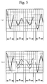
- Fig. 5 is a graph showing the load applied to and the contact pressure of the balls when radial force is acting upon the rack shaft (in the case that d2=1. d1=d);
- Fig. 6 is a graph showing the load applied to and the contact pressure of the balls when radial force is acting upon the rack shaft (in the case that d2=1.1d1, d1=d);
- Fig. 7 is a graph showing the load applied to and the contact pressure of the balls when radial force is acting upon the rack shaft (in the case that d2=1.005d1, d1=d);
- Fig. 8 is a graph showing the load applied to the balls when radial force is acting upon the rack shaft (in the case that d2=1.105d1, d1=d);
- Fig. 9 is a graph showing the load applied to the balls when radial force is acting upon the rack shaft (in the case that d1=0.95d2 d2=d); and
- Fig. 10 is a graph showing the nonuniform rate of the balls and amount of load variation.
-
- Hereinafter, a preferred embodiment of the deflector type ball screw according to the aforementioned invention will be described.
- Referring to Fig. 1, hereinafter a structure of a power steering device (hereafter referred to as electric PS device) including the deflector type ball screw will be described. Fig. 1 is a schematic system diagram of the electric PS device.
- The
Electric PS device 60 includes asteering wheel 40, ashaft 62 that transmits a steering torque of the steering wheel, apinion 44 fixed to a tip of theshaft 62 and arack shaft 26 having rack teeth that engage with thepinion 44. A rack andpinion mechanism 50 composed of thepinion 44 and therack shaft 26. Furthermore, theelectric PS device 60 includes steering torque detection means 42 that detects a steering torque of thesteering wheel 40, control means 46 that generates a control signal based on a detection signal of the steering torque detection means 42, anelectric motor 48 that generates auxiliary torque based on the control signal of the control means 46 and a deflectortype ball screw 20 that transmits the auxiliary torque of theelectric motor 48 to therack shaft 26. - Rack teeth that engage with the
pinion 44 are formed in a longitudinal direction portion of therack shaft 26, and a screw groove constituting the deflectortype ball screw 20 is formed in another longitudinal direction portion of therack shaft 26. Furthermore, atie rod 52 is fixed to each end of therack shaft 26. Eachtie rod 52 is connected to one end of arespective knuckle arm 54, and eachwheel 56 is mounted to another end of eachrespective knuckle arm 54. - With regard to the steering torque detection means 42 and the control means 46 that are components of the
electric PS device 60, any components maybe employed as long as they are the same components as those provided in known electric PS devices. These components are not characteristics of the present invention. - Referring to Fig. 2, hereinafter a structure of the
electric motor 48 and the deflectortype ball screw 20 will be described in detail. Fig. 2 is a cross section view of the main portions of therack shaft 26, theelectric motor 48 and deflectortype ball screw 20. - An
entire housing 3 is divided into three sections, that is, a first housing 2, asecond housing 4 and athird housing 6, which are connected bybolts second housing 4 at the center. Eachhousing entire housing 3, which is formed by theconnected housings - A
stator 12 constituting theelectric motor 48 is housed inside thesecond housing 4, and astator coil 15 is provided inside thestator 12. Furthermore, arotor 13 that constitutes theelectric motor 48 with thestator 12 is housed in a space inside of thestator coil 15. Therotor 13 is supported such that it is rotatable but immovable in an axial direction by abearing 18 provided on thesecond housing 4 and abearing 22 provided on thethird housing 6. Therotor 13 is constituted from thestator coil 15, amagnet 16 located facing thestator coil 15 and anoutput shaft 14 has a substantially cylindrical shape. Aball nut 24 is fixed to an inner surface of one end portion of theoutput shaft 14. - The
rack shaft 26 extends through theentire housing 3 that has a substantially cylindrical shape. Therack shaft 26 is slidable with respect to theentire housing 3 and is prevented from rotating with respect to theentire housing 3 by a mechanism not shown. Anexternal thread groove 28a is formed in a longitudinal portion of therack shaft 26. Theexternal thread groove 28a has a length equal to the distance that therack shaft 26 slides, and constitutes theball screw 20 with theball nut 24. In this specification, the portion of therack shaft 26 in which theexternal thread groove 28a is formed is referred to as ascrew shaft 28.Rack teeth 30 that engage with thepinion 44 are formed in a longitudinal direction portion of the rack shaft 26 (in a portion other than the screw shaft 28). Therack teeth 30 are formed over a length equal to the distance that rackshaft 26 slides. - Referring to Fig. 3, hereinafter the structure of the deflector
type ball screw 20 will be described in further detail. Fig. 3 is a cross section view of the components of the deflectortype ball screw 20. - As shown in Fig. 3, a plurality of
balls 72 are rollably housed between aninternal thread groove 24a of theball nut 24 and anexternal thread groove 28a of thescrew shaft 28. Fourdeflectors 70a to 70d are embedded in theball nut 24. The fourdeflectors 70a to 70d are positioned with the same distance between them in an axial direction of theball nut 24, and are offset 90° from each other in a circumferential direction. Therespective deflectors 70a to 70d haverespective guidance grooves 71a to 71d for guidingballs 72 so that they can return to anadjacent screw groove 28a passing beyond arespective screw thread 28b of thescrew shaft 28. Thedeflectors 70a to 70d function as by-passes linking adjacentinternal thread grooves 24a of theball nut 24. As a result ofdeflectors 70a to70d guiding balls 72, thescrew groove 24a of theball nut 24 is divided into fourcirculation passages 74a to 74d. Hereinafter, theballs 72 that are rollably housed in the first tofourth circulation passages 74a to 74d will be referred to as the first to fourth ball groups, respectively. - In this embodiment, a diameter of the balls of the second and
third ball groups fourth ball groups ball groups 72a to 72 d have the same diameter; a diameter d1 is the ball diameter of the first andfourth ball groups third ball groups - Hereinafter, the operation of the
electric PS device 60 will be described. When thesteering wheel 40 is steered, thepinion 44 revolves. As a result of thepinion 44 revolving, therack shaft 26 having therack teeth 30 engaged with thepinion 44, moves in either of an axial direction in accordance with the rotation direction of thepinion 44. - Moreover, the steering torque of the
steering wheel 40 is detected by the steering torque detection means 42 using a torsional angle of theshaft 62. The torsional angle detected by the steering torque detection means 42 is converted into a predetermined detection signal and output to the control means 46. The control means 46 that receives the detection signal, outputs a signal such that auxiliary torque is generated to theelectric motor 48. Theelectric motor 48 that receives the signal from the control means 46 passes current into thestator coil 15 in accordance with the received signal. A magnetic field is generated in thestator coil 15, and as a result therotor 13 including the magnetic 16 is rotated in either of a forward or reverse direction. Thebolt 24 fixed to theoutput shaft 14 also rotates along with the rotation of therotor 13. When thebolt 24 rotates, a thrust force acts upon the external thread groove of thescrew shaft 28 through theballs 72 housed in eachcirculation passage 74a to 74d. Therack shaft 28 is moved in the axial direction by this thrust force. - In this manner, both the torque from the
pinion 44 and the auxiliary torque from theelectric motor 48 are transmitted to therack shaft 26, thus moving therack shaft 28 in the axial direction. When therack shaft 28 is moved in the axial direction, thewheels 56 are turned bytie rods 52 fixed to therack shaft 28 and knucklearms 54 that are connected to thetie rods 52. - The
electric PS device 60 assists the steering effort of the steering wheel of the driver using the generation of auxiliary torque by theelectric motor 48. - Referring to Fig. 4 to Fig. 9, estimated results derived by computer analysis are shown for the load applied to and contact pressure of each ball group when the diameters of the balls of the first to
fourth ball groups 72a to 72d are changed and when a force (a force F in Fig. 3) is applied to therack shaft 26 in a radial direction. Symbols A to D shown on horizontal axes of Fig. 4 to Fig. 9 represent the first tofourth ball groups 72a to 72d. Vertical axes of each Figure (a) show the load applied to each ball. Vertical axes of each figure (b) show the contact pressure of each ball (more precisely, since the contact pressure of each ball is distributed across the surface of the ball, the maximum contact pressure among all of the contact pressures was estimated). However, Fig. 8 shows only the load applied to each ball and does not show estimated results for contact pressure. Furthermore, each figure shows plot points that have been linked by a smoothed line for the estimated results of the load applied to and contact pressure of each ball. - Referring to Fig. 4, estimated results for a case in which the ball diameters of the first to fourth ball groups are uniform (in a case when d1=d2=d) will be described. The ball diameter (d) selected is an appropriate ball diameter, namely, the nominal diameter. This diameter was employed by persons skilled in the art while taking into consideration a width and a depth of each
screw groove - As shown in Fig. 4(a), the load applied to many of the balls of the first and
fourth ball groups third ball groups fourth ball groups - Referring to Fig. 5 to Fig. 8, estimated results in a case when the ball diameter of the first to
fourth ball groups third ball groups third ball groups - Fig. 5 shows estimated results in the case that d2=1.05d1.
- As shown in Fig. 5(a), as compared to the case in which the balls have a uniform diameter, the load applied to the first and
fourth ball groups third ball groups - Furthermore, as shown in Fig. 5(b), the contact pressure of the first and
fourth ball groups third ball groups - Fig. 6 shows estimated results in a case that d2=1.d1.
- As shown in Fig. 6(a), the load applied to the first and
fourth ball groups third ball groups fourth ball groups - As shown in Fig. 6(b), the load applied to the first and
fourth ball groups fourth ball groups third ball groups third ball groups - Figure 7 shows estimated results in a case in which d2=1.005d1.
- As shown in Fig. 7(a), the load applied to the first and
fourth ball groups third ball groups - It is clear from Fig. 7 (b) that the contact pressure of all of the
ball groups 72a to 72d is reduced. - It is apparent from these estimated results that if d2 is less than 1.005 times d1, then the load applied to the first and
fourth ball groups - Fig. 8 shows estimated results for the load applied to each ball group in the case that d2=1.105d.
- As shown in Fig. 8, it is clear that in this case there are balls in the first and
fourth ball groups fourth ball groups - Fig. 9 shows estimated results for the load applied to and contact pressure of each ball in a ball screw having balls of the second and
third ball groups fourth ball groups rack shaft 26 in a manner similar to that previously mentioned. The horizontal and vertical axes of Fig. 9(a) and (b) are the same as aforementioned Fig. 4 to Fig. 7. The solid lines in Fig. 9 show estimated results for the case that d1=d2=d, and the broken lines are for the case that d1=0.95d2. - As shown in Fig. 9(a), the load applied to the first and
fourth ball groups - Meanwhile, as shown in Fig. 9(b), the load applied to the balls of the second and
third ball groups fourth ball groups - Fig. 10 shows estimated results for the amount of load variation when the radial force F is applied in a case that d1=d and d2 is larger than the nominal diameter. The amount of load variation is the difference between the load of the ball that has the largest applied load and the load of the ball that has the smallest applied load. By estimating the amount of load variation, it becomes possible to evaluate whether the balance of the load applied to the balls is good or bad. The balance of the load applied to the balls improves as the amount of load variation is reduced.
- The horizontal axis of Fig. 10 shows a value of d2/d1 when d2 has been changed. Hereinafter, this value will be referred to as the nonuniform rate. The vertical axis of Fig. 10 shows the amount of load variation.
- As shown in Fig. 10, the amount of load variation is reduced as the nonuniform rate is increased up to the vicinity of 1.075. However, when the nonuniform rate exceeds 1.075, the amount of load variation is increased while the rate of this increase rises.
- Based on the estimated results of Fig. 10, it is possible to conclude that the balance of the load applied to balls is substantially excellent when the nonuniform rate is 1.005 or greater, compared to the case in which the balls have a uniform diameter (in the case that d2/d1=1). Moreover, if the amount of load variation when the nonuniform rate is 1.005 is set as a reference, then the upper limit of the nonuniform rate is at 1.102. However, since the rate of increase of the amount of load variation in this vicinity is high, it is preferable to set the upper limit to 1.1.
- The estimated results of previously explained Fig. 4 to Fig. 10 show that if d2 is 1.005 times d1 or more, when the radial force F is acting upon the
rack shaft 26 forming thescrew shaft 28, the load applied to the first andfourth ball groups fourth ball groups fourth ball groups third ball groups type ball screw 20 according to the embodiment, when the radial force F is acting upon therack shaft 26, damage ofdeflectors 70a to 70d, theball nut 24 and thescrew shaft 28 constituting the deflectortype ball screw 20, is reliably reduced (suppressed), compared to the case in which the balls have a uniform diameter. - Moreover, if the ball diameter of the balls of the second and
third ball groups fourth ball groups fourth ball groups rack shaft 26, vibrations or noise are eliminated or suppressed, thereby eliminating or reducing a sense of discomfort of the driver. - Furthermore, due to the range of d1 and d2 selected for the deflector
type ball screw 20 according to the embodiment, an outstanding balance of the load applied to the balls is realized. - While the invention has been described in detail with reference to the preferred embodiment, it will be apparent to those skilled in the art that the invention is not limited to the present embodiment, and that the invention may be realized in various other embodiments within the scope of the claims.
- For example, in the aforementioned embodiment the four
circulation passages 74a to 74d are formed in the deflectortype ball screw 20. However, it is possible to make appropriate changes to the number of circulation passages. Moreover, Fig. 4 and the figures thereafter show cases in which a force acts upon the screw shaft of the ball screw in a radial direction. However, it has also been confirmed that when a load acts in a sliding direction as well, the load is equalized and contact pressure is reduced. - Furthermore, the technological components described in this specification and illustrated in the drawings can demonstrate their technological usefulness independently through various other combinations which are not limited to the combinations described in the claims made at the time of application. Moreover, the art described in this specification and illustrated in the drawings can simultaneously achieve a plurality of objectives, and is technologically useful by virtue of realizing any one of these objectives.
- A deflector type ball screw includes a screw shaft having an external thread groove in an outer peripheral surface, a ball nut having an internal thread groove in an inner peripheral surface and a plurality of balls that are rollably housed between the internal thread groove and the external thread groove, and four deflectors fixed to the ball nut. The deflectors function as by-passes linking adjacent internal thread grooves of the ball nut. As a result of the deflectors guiding the balls, the screw groove of the ball nut is divided into four circulation passages.
- When a diameter d is the nominal diameter used in a case in which all of the balls of
ball groups 72a to 72 d have the same diameter; a diameter d1 is the ball diameter of the ball groups housed in first and fourth circulation passages; and a diameter d2 is the ball diameter of the ball groups housed in second and third circulation passages, d1=d and the relationship of 1.005d1 ≦d2≦1.1d1 is satisfied.
Claims (3)
- A ball screw, comprising:a screw shaft having an external thread groove in an outer peripheral surface; anda ball nut having an internal thread groove in an inner peripheral surface; anda plurality of balls rollably housed between the external thread groove and the internal thread groove, the internal thread groove of the ball nut being divided into at least three circulation passages in an axial direction of the ball nut, wherein;a diameter of the balls housed in the circulation passages at the axial direction end portions of the ball nut is d1, a diameter of balls housed in the one or more circulation passages inward in an axial direction from the end portion circulation passages is d2, and a relationship between the d1 and the d2 is set such that 1.005d1 ≦ d2≦1.1d1.
- The ball screw according to Claim 1, wherein the d1 is set to be substantially equal to a diameter d, which is an appropriate ball diameter in a case in which balls with a uniform diameter are used in all of the circulation passages.
- An electric power steering including the ball screw according to Claim 1 or Claim 2.
Applications Claiming Priority (2)
| Application Number | Priority Date | Filing Date | Title |
|---|---|---|---|
| JP2001282081A JP2003090410A (en) | 2001-09-17 | 2001-09-17 | Ball screw divided into plural circulation passages |
| JP2001282081 | 2001-09-17 |
Publications (2)
| Publication Number | Publication Date |
|---|---|
| EP1293706A2 true EP1293706A2 (en) | 2003-03-19 |
| EP1293706A3 EP1293706A3 (en) | 2006-05-10 |
Family
ID=19105781
Family Applications (1)
| Application Number | Title | Priority Date | Filing Date |
|---|---|---|---|
| EP02020763A Withdrawn EP1293706A3 (en) | 2001-09-17 | 2002-09-16 | Ball screw having multiply divided circulation passages |
Country Status (3)
| Country | Link |
|---|---|
| US (1) | US20030066372A1 (en) |
| EP (1) | EP1293706A3 (en) |
| JP (1) | JP2003090410A (en) |
Cited By (6)
| Publication number | Priority date | Publication date | Assignee | Title |
|---|---|---|---|---|
| FR2867825A1 (en) * | 2004-06-18 | 2005-09-23 | Koyo Seiko Co | Ball screw mechanism for electric power steering apparatus, has two ball circulating holes bored at midway at screw groove formed on inner circumference of ball nut fitted outside ball screw portion |
| US7322256B2 (en) | 2003-03-25 | 2008-01-29 | Koyo Seiko Co. Ltd. | Ball screw mechanism for electric power steering apparatus |
| CN104500670A (en) * | 2014-11-17 | 2015-04-08 | 西安航空制动科技有限公司 | Inner circulation ball screw component for airplane electric brake |
| WO2016188528A1 (en) * | 2015-05-27 | 2016-12-01 | Schaeffler Technologies AG & Co. KG | Ball screw drive |
| EP3121476A1 (en) * | 2015-07-21 | 2017-01-25 | Goodrich Corporation | Aircraft brake actuator assemblies |
| CN114673770A (en) * | 2020-12-24 | 2022-06-28 | 上银科技股份有限公司 | External circulation ball screw |
Families Citing this family (10)
| Publication number | Priority date | Publication date | Assignee | Title |
|---|---|---|---|---|
| JP2005263149A (en) * | 2004-03-22 | 2005-09-29 | Nsk Ltd | Electric power steering device |
| US20080129133A1 (en) * | 2004-03-31 | 2008-06-05 | Danaher Motion Stockholm Ab | Electric Actuator |
| WO2009100332A2 (en) * | 2008-02-06 | 2009-08-13 | Trw Automotive U.S. Llc | Ball screw and nut assembly |
| JP2010048276A (en) * | 2008-08-19 | 2010-03-04 | Ntn Corp | Ball screw |
| JP5420922B2 (en) * | 2009-02-06 | 2014-02-19 | 株式会社日本自動車部品総合研究所 | Electric power steering device |
| JP5168503B2 (en) * | 2009-03-24 | 2013-03-21 | 株式会社ジェイテクト | Ball screw device and electric power steering device |
| JP5953836B2 (en) * | 2012-03-09 | 2016-07-20 | 株式会社ジェイテクト | Electric power steering device |
| JP6491832B2 (en) * | 2014-07-24 | 2019-03-27 | Thk株式会社 | Finite speed reducer |
| DE102015214859B4 (en) * | 2015-08-04 | 2017-12-14 | Schaeffler Technologies AG & Co. KG | Ball Screw |
| WO2019133855A1 (en) * | 2017-12-29 | 2019-07-04 | Kelsey-Hayes Company | Ball nut assembly |
Citations (2)
| Publication number | Priority date | Publication date | Assignee | Title |
|---|---|---|---|---|
| JPH1111334A (en) | 1997-06-25 | 1999-01-19 | Honda Motor Co Ltd | Electric power steering device |
| JP2000072008A (en) | 1998-08-31 | 2000-03-07 | Nippon Seiko Kk | Electric power steering device |
Family Cites Families (3)
| Publication number | Priority date | Publication date | Assignee | Title |
|---|---|---|---|---|
| US6082209A (en) * | 1996-09-30 | 2000-07-04 | Nsk Ltd. | Ball screw |
| JP3714026B2 (en) * | 1999-05-10 | 2005-11-09 | 日本精工株式会社 | Ball screw |
| JP2001065662A (en) * | 1999-08-26 | 2001-03-16 | Fanuc Ltd | Ball screw |
-
2001
- 2001-09-17 JP JP2001282081A patent/JP2003090410A/en active Pending
-
2002
- 2002-09-16 EP EP02020763A patent/EP1293706A3/en not_active Withdrawn
- 2002-09-17 US US10/244,551 patent/US20030066372A1/en not_active Abandoned
Patent Citations (2)
| Publication number | Priority date | Publication date | Assignee | Title |
|---|---|---|---|---|
| JPH1111334A (en) | 1997-06-25 | 1999-01-19 | Honda Motor Co Ltd | Electric power steering device |
| JP2000072008A (en) | 1998-08-31 | 2000-03-07 | Nippon Seiko Kk | Electric power steering device |
Cited By (9)
| Publication number | Priority date | Publication date | Assignee | Title |
|---|---|---|---|---|
| US7322256B2 (en) | 2003-03-25 | 2008-01-29 | Koyo Seiko Co. Ltd. | Ball screw mechanism for electric power steering apparatus |
| FR2867825A1 (en) * | 2004-06-18 | 2005-09-23 | Koyo Seiko Co | Ball screw mechanism for electric power steering apparatus, has two ball circulating holes bored at midway at screw groove formed on inner circumference of ball nut fitted outside ball screw portion |
| CN104500670A (en) * | 2014-11-17 | 2015-04-08 | 西安航空制动科技有限公司 | Inner circulation ball screw component for airplane electric brake |
| WO2016188528A1 (en) * | 2015-05-27 | 2016-12-01 | Schaeffler Technologies AG & Co. KG | Ball screw drive |
| CN107646083A (en) * | 2015-05-27 | 2018-01-30 | 舍弗勒技术股份两合公司 | Ball screw drive |
| US20180087635A1 (en) * | 2015-05-27 | 2018-03-29 | Schaeffler Technologies AG & Co. KG | Ball screw drive |
| CN107646083B (en) * | 2015-05-27 | 2021-04-27 | 舍弗勒技术股份两合公司 | Ball screw drive |
| EP3121476A1 (en) * | 2015-07-21 | 2017-01-25 | Goodrich Corporation | Aircraft brake actuator assemblies |
| CN114673770A (en) * | 2020-12-24 | 2022-06-28 | 上银科技股份有限公司 | External circulation ball screw |
Also Published As
| Publication number | Publication date |
|---|---|
| JP2003090410A (en) | 2003-03-28 |
| US20030066372A1 (en) | 2003-04-10 |
| EP1293706A3 (en) | 2006-05-10 |
Similar Documents
| Publication | Publication Date | Title |
|---|---|---|
| US20030066372A1 (en) | Ball screw having multiply divided circulation passages | |
| EP1630456B1 (en) | Ball screw and electric power steering device including the same | |
| CN103153756B (en) | Ball-screw apparatus, linear actuators and wheel steering system | |
| KR100895592B1 (en) | Electric power steering device for vehicle imparting assist power to rotating member surrounding tie rod connection bar | |
| EP2226235A1 (en) | Electric power steering apparatus | |
| EP2110580A1 (en) | Ball screw mechanism and electric power steering device using the same | |
| CN104015786B (en) | Ball screw type electric power steering apparatus | |
| WO2007026801A1 (en) | Steering device and movement converting device used therefor | |
| CN115135563A (en) | Steer-by-wire steering device | |
| US20070209465A1 (en) | Screw Device And Method Of Manufacturing The Same | |
| JP2003014055A (en) | Backlash adjustment device for worm reduction gear | |
| EP1970288A1 (en) | Steering control device for vehicle | |
| US7159690B2 (en) | Electric power steering apparatus | |
| JP2003160812A (en) | Ball screw for wheel-steering | |
| JP2003097661A (en) | Ball screw and wheel steering system using it | |
| JP4381031B2 (en) | Electric power steering device | |
| EP1666335A1 (en) | Electronic control power steering device | |
| JP2006329258A (en) | Rotational linear motion conversion mechanism | |
| JP2005321043A (en) | Rotational linear motion conversion mechanism | |
| JP7512696B2 (en) | Ball screw device and manufacturing method thereof | |
| JP4049048B2 (en) | Electric power steering device | |
| JP4574228B2 (en) | Ball screw for electric actuator | |
| JPH06505B2 (en) | Electric power steering device | |
| CN211167077U (en) | Recirculating ball steering gear | |
| KR101477896B1 (en) | Electric power steering apparatus of ball screw type |
Legal Events
| Date | Code | Title | Description |
|---|---|---|---|
| PUAI | Public reference made under article 153(3) epc to a published international application that has entered the european phase |
Free format text: ORIGINAL CODE: 0009012 |
|
| AK | Designated contracting states |
Kind code of ref document: A2 Designated state(s): AT BE BG CH CY CZ DE DK EE ES FI FR GB GR IE IT LI LU MC NL PT SE SK TR Designated state(s): AT BE BG CH CY CZ DE DK EE ES FI FR GB GR IE IT LI LU MC NL PT SE SK TR |
|
| AX | Request for extension of the european patent |
Extension state: AL LT LV MK RO SI |
|
| PUAL | Search report despatched |
Free format text: ORIGINAL CODE: 0009013 |
|
| AK | Designated contracting states |
Kind code of ref document: A3 Designated state(s): AT BE BG CH CY CZ DE DK EE ES FI FR GB GR IE IT LI LU MC NL PT SE SK TR |
|
| AX | Request for extension of the european patent |
Extension state: AL LT LV MK RO SI |
|
| RAP1 | Party data changed (applicant data changed or rights of an application transferred) |
Owner name: JTEKT CORPORATION |
|
| RIN1 | Information on inventor provided before grant (corrected) |
Inventor name: FUKUMURA, KENICHIC/O JTEKT CORPORATION Inventor name: ISHIGAMI, TOSHIYAJTEKT CORPORATION Inventor name: KOBAYASHI, TSUNEC/O JTEKT CORPORATION |
|
| AKX | Designation fees paid |
Designated state(s): DE FR GB |
|
| STAA | Information on the status of an ep patent application or granted ep patent |
Free format text: STATUS: THE APPLICATION IS DEEMED TO BE WITHDRAWN |
|
| 18D | Application deemed to be withdrawn |
Effective date: 20061111 |