EP1293674A1 - Scrawl compressor - Google Patents
Scrawl compressor Download PDFInfo
- Publication number
- EP1293674A1 EP1293674A1 EP01941106A EP01941106A EP1293674A1 EP 1293674 A1 EP1293674 A1 EP 1293674A1 EP 01941106 A EP01941106 A EP 01941106A EP 01941106 A EP01941106 A EP 01941106A EP 1293674 A1 EP1293674 A1 EP 1293674A1
- Authority
- EP
- European Patent Office
- Prior art keywords
- scroll
- orbiting scroll
- wall
- end plate
- fixed scroll
- Prior art date
- Legal status (The legal status is an assumption and is not a legal conclusion. Google has not performed a legal analysis and makes no representation as to the accuracy of the status listed.)
- Granted
Links
Images






Classifications
-
- F—MECHANICAL ENGINEERING; LIGHTING; HEATING; WEAPONS; BLASTING
- F04—POSITIVE - DISPLACEMENT MACHINES FOR LIQUIDS; PUMPS FOR LIQUIDS OR ELASTIC FLUIDS
- F04C—ROTARY-PISTON, OR OSCILLATING-PISTON, POSITIVE-DISPLACEMENT MACHINES FOR LIQUIDS; ROTARY-PISTON, OR OSCILLATING-PISTON, POSITIVE-DISPLACEMENT PUMPS
- F04C18/00—Rotary-piston pumps specially adapted for elastic fluids
- F04C18/02—Rotary-piston pumps specially adapted for elastic fluids of arcuate-engagement type, i.e. with circular translatory movement of co-operating members, each member having the same number of teeth or tooth-equivalents
-
- F—MECHANICAL ENGINEERING; LIGHTING; HEATING; WEAPONS; BLASTING
- F04—POSITIVE - DISPLACEMENT MACHINES FOR LIQUIDS; PUMPS FOR LIQUIDS OR ELASTIC FLUIDS
- F04C—ROTARY-PISTON, OR OSCILLATING-PISTON, POSITIVE-DISPLACEMENT MACHINES FOR LIQUIDS; ROTARY-PISTON, OR OSCILLATING-PISTON, POSITIVE-DISPLACEMENT PUMPS
- F04C18/00—Rotary-piston pumps specially adapted for elastic fluids
- F04C18/02—Rotary-piston pumps specially adapted for elastic fluids of arcuate-engagement type, i.e. with circular translatory movement of co-operating members, each member having the same number of teeth or tooth-equivalents
- F04C18/0207—Rotary-piston pumps specially adapted for elastic fluids of arcuate-engagement type, i.e. with circular translatory movement of co-operating members, each member having the same number of teeth or tooth-equivalents both members having co-operating elements in spiral form
- F04C18/0246—Details concerning the involute wraps or their base, e.g. geometry
- F04C18/0269—Details concerning the involute wraps
- F04C18/0276—Different wall heights
-
- F—MECHANICAL ENGINEERING; LIGHTING; HEATING; WEAPONS; BLASTING
- F04—POSITIVE - DISPLACEMENT MACHINES FOR LIQUIDS; PUMPS FOR LIQUIDS OR ELASTIC FLUIDS
- F04C—ROTARY-PISTON, OR OSCILLATING-PISTON, POSITIVE-DISPLACEMENT MACHINES FOR LIQUIDS; ROTARY-PISTON, OR OSCILLATING-PISTON, POSITIVE-DISPLACEMENT PUMPS
- F04C23/00—Combinations of two or more pumps, each being of rotary-piston or oscillating-piston type, specially adapted for elastic fluids; Pumping installations specially adapted for elastic fluids; Multi-stage pumps specially adapted for elastic fluids
- F04C23/008—Hermetic pumps
-
- F—MECHANICAL ENGINEERING; LIGHTING; HEATING; WEAPONS; BLASTING
- F04—POSITIVE - DISPLACEMENT MACHINES FOR LIQUIDS; PUMPS FOR LIQUIDS OR ELASTIC FLUIDS
- F04C—ROTARY-PISTON, OR OSCILLATING-PISTON, POSITIVE-DISPLACEMENT MACHINES FOR LIQUIDS; ROTARY-PISTON, OR OSCILLATING-PISTON, POSITIVE-DISPLACEMENT PUMPS
- F04C27/00—Sealing arrangements in rotary-piston pumps specially adapted for elastic fluids
- F04C27/005—Axial sealings for working fluid
-
- F—MECHANICAL ENGINEERING; LIGHTING; HEATING; WEAPONS; BLASTING
- F04—POSITIVE - DISPLACEMENT MACHINES FOR LIQUIDS; PUMPS FOR LIQUIDS OR ELASTIC FLUIDS
- F04C—ROTARY-PISTON, OR OSCILLATING-PISTON, POSITIVE-DISPLACEMENT MACHINES FOR LIQUIDS; ROTARY-PISTON, OR OSCILLATING-PISTON, POSITIVE-DISPLACEMENT PUMPS
- F04C28/00—Control of, monitoring of, or safety arrangements for, pumps or pumping installations specially adapted for elastic fluids
- F04C28/24—Control of, monitoring of, or safety arrangements for, pumps or pumping installations specially adapted for elastic fluids characterised by using valves controlling pressure or flow rate, e.g. discharge valves or unloading valves
- F04C28/26—Control of, monitoring of, or safety arrangements for, pumps or pumping installations specially adapted for elastic fluids characterised by using valves controlling pressure or flow rate, e.g. discharge valves or unloading valves using bypass channels
- F04C28/265—Control of, monitoring of, or safety arrangements for, pumps or pumping installations specially adapted for elastic fluids characterised by using valves controlling pressure or flow rate, e.g. discharge valves or unloading valves using bypass channels being obtained by displacing a lateral sealing face
Definitions
- the present invention relates to scroll compressors provided in air conditioners, refrigerators, or the like.
- a scroll compressor is a compressor in which a fixed scroll and an orbiting scroll are arranged as a pair of spiral walls assembled together, and the orbiting scroll is orbitally moved with respect to the fixed scroll in order to gradually reduce the volume of a compression chamber formed between the walls and thereby compress the fluid inside the compression chamber.
- A( ⁇ ) is a function representing the cross-sectional area parallel to the orbital plane of the compression chamber for which the volume is changed corresponding to the orbital angle ⁇ of the orbiting scroll
- ⁇ suc is the orbital angle of the orbiting scroll when the compression chamber reaches maximum volume
- ⁇ top is the orbital angle of the orbiting scroll when the compression chamber reaches minimum volume
- L is the length of the lap (overlap) of the pair of walls.
- Japanese Examined Patent Application, Second Publication, No. 60-17956 discloses the following techniques.
- the device shown in Fig. 12A is a fixed scroll 50, and comprises an end plate 50a and a wall 50b of a spiral shape standing on one side face of the end plate 50a. Furthermore, the device shown in Fig. 12B is an orbiting scroll 51.
- the orbiting scroll 51 also comprises an end plate 51a and a spiral wall 51b standing on one side face of the end plate 51a, similar to that of the fixed scroll 50.
- a step portion 52 is provided on the side surface of the end plate 50a of the fixed scroll 50 at the point of ⁇ radians from the outer end to the center direction along the spiral wall 50b.
- the step portion 52 has two parts in which one part is high at the center side of the side surface of the end plate 50a and the other part is low at the outer end side of the end plate 50a.
- a step portion 53 is provided on a spiral top edge of the wall body 50b of the fixed scroll 50.
- the step portion 53 has two parts in which one part is low at the center side of the spiral top edge and the other part is high at the outer end side of the spiral top edge.
- a step portion 52 is provided on the side surface of the end plate 51a of the orbiting scroll 51 at the point of ⁇ radians from the outer end to the center direction along the spiral wall 51b.
- the step portion 52 has two parts in which one part is high at the center side of the side surface of the end plate 51a and the other part is low at the outer end side of the end plate 51a.
- a step portion 53 is provided on a spiral top edge of the wall body 51b of the orbiting scroll 51.
- the step portion 53 has two parts in which one part is low at the center side of the spiral top edge and the other part is high at the outer end side of the spiral top edge.
- Tip seals are provided on the top edges of the wall bodies 50b and 51b in order to improve airtightness.
- Fig. 13A the wall body 50b of the fixed scroll 50 and the wall body 51b of the orbiting scroll 51a are engaged with each other to form a compression chamber P having the maximum capacity; this is shown in Fig. 13A.
- Fig. 13B is a cross-sectional view of the compression chamber P along the spiral wall body.
- the lap length L1 which is further out than the step portion 52 is longer than the lap length Ls which is further in than the step portion 52.
- the maximum capacity of the compression chamber P increases as the lap length of the wall body, which is further out than the step portion 52, becomes larger, in comparison with the maximum capacity of the compression chamber having the uniform lap length. Consequently, the compression ratio in the design can be increased without increasing the number of spiral laps of the wall body.
- a part of the tip seal 56 which is placed in the vicinity of the step portion 53 may disengage from the end plate 50a of the fixed scroll 50 when the orbiting scroll 51 comes to a phase thereof by orbitally moving.
- a part of the tip seal 54 of the fixed scroll 50, which is placed in the vicinity of the step portion 52, may similarly disengage from the end plate 51a of the orbiting scroll 51.
- tip seals 54 and 56 tend to fall off from the wall bodies 50b and 51b or leakage of fluid occurs at the step portions because tip seals 54 and 56 tend to bend.
- an object of the present invention is to provide a scroll compressor preventing leakage of fluid.
- the present invention provides a scroll compressor comprising: a fixed scroll having a spiral wall standing on one side face of an end plate, and secured in place; and an orbiting scroll having a spiral wall standing on one side face of an end plate, and supported so as to be orbitally movable while being prevented from rotation, with the pair of walls engaged with each other, wherein a back pressure chamber is provided on the other side face of the end plate of at least one of the fixed scroll and the orbiting scroll, and the one scroll is pressed against the other scroll by introducing fluid which is compressed by the fixed scroll and the orbiting scroll into the back pressure chamber; a step portion is provided on the one side face of the end plate of at least one of the fixed scroll and the orbiting scroll, which has a high part with a height thereof which is high at a central side in a spiral direction, and a low part with a height thereof which is low at an outer peripheral end side; and an upper rim of the wall of the other of the fixed scroll and the orbiting scroll is divided into a plurality of parts to form a
- the above scroll compressor at least one of the fixed scroll and the orbiting scroll is pressed on the other scroll by the compressed fluid introduced in the back pressure chamber. Accordingly, differently from the conventional method, even if tip seals are not used, the compression chamber is sealed, preventing leakage of fluid in the compression chamber. Therefore, problems in which the tip seal falls off, bends, or the like when a gap appears between the tip seal and the end plate do not occur.
- the scroll compressor of the present invention may comprise an elastic body for pressing at least one of the fixed scroll and the orbiting scroll against the other scroll.
- the back pressure chamber may be provided on the other side face of the fixed scroll.
- the back pressure chamber may be provided on the other side face of the orbiting scroll.
- the scroll compressor of the present invention may comprise bearing member which performs orbital movement while engaging the other side face of the end plate of the orbiting scroll, wherein the back pressure chamber is provided between the orbiting scroll and the bearing member.
- the compressed fluid which is introduced in the back pressure chamber exerts pressure to spread a gap between the orbiting scroll and the bearing member. Accordingly, the orbiting scroll is pressed on the fixed scroll.
- FIG. 1 A first embodiment of the scroll compressor according to the present invention will be explained with reference to Fig. 1 to Figs. 9A to 9D.
- Fig. 1 illustrates an overall construction of a back pressure scroll compressor shown as an embodiment of the present invention.
- the back pressure scroll compressor comprises a sealed housing 1, a discharge cover 2 for separating the housing 1 interior into a high pressure chamber HR and a low pressure chamber LR, a frame 5, a suction pipe 6, a discharge pipe 7, a motor 8, a rotating shaft 16, a rotation prevention mechanism 10, a fixed scroll 12, and an orbiting scroll 13 engaged with the fixed scroll 12.
- the construction is such that for the fixed scroll 12, a spiral wall 12b is standing on one side face of an end plate 12a.
- the construction is such that a spiral wall 13b is standing on one side face of an end plate 13a as with the fixed scroll 12.
- the wall 13b is made substantially in the same shape as the wall 12b for the fixed scroll 12 side.
- the orbiting scroll 13 is assembled to the fixed scroll 12, eccentric thereto by an orbital radius and out of phase by 180 degrees, with the walls 12b and 13b engaged with each other.
- the fixed scroll 12 is not completely secured to the frame 5 with bolts or the like, and can move within a restricted range.
- a cylindrical boss A is formed on the rear face side of the orbiting scroll 13, and an eccentric pin 9a provided on an upper end of the rotation shaft 9 which is driven by the motor 8 for orbital movement, is inserted into the boss A.
- the orbiting scroll 13 performs orbital movement with respect to the fixed scroll 12, while rotation thereof is prevented by the action of the rotation prevention mechanism 10.
- the fixed scroll 12 is supported so as to float freely with respect to the frame 5 secured to the housing 1 via a support spring (elastic body) 11, and is pressed against the orbiting scroll 13.
- a discharge port 15 for compressed fluid is provided in the center of the rear face of the end plate 3a. Furthermore, around the discharge port 15 there is provided a cylindrical flange 16 protruding from the rear face of the end plate 12a of the fixed scroll 12, and this cylindrical flange 16 is engaged with a cylindrical flange 17 on the discharge cover 2 side.
- the high pressure chamber HR and the low pressure chamber LR are separated, and since it is necessary to apply the high pressure (back pressure) to the rear face of the fixed scroll 12 to press it downwards, a seal structure using a seal member 15 is adopted.
- This seal member 15 has a U-shaped cross-section.
- the high pressure chamber HR in this case also functions as a back pressure chamber which applies the high pressure discharge pressure to the rear face of the fixed scroll 12.
- step portion 42 formed so that it is high on the central portion side along the spiral direction of the wall 12b and low on the outer peripheral end side.
- a step portion 43 formed so as to be high on the central portion side along the spiral direction of the wall 13b and low on the outer peripheral end side.
- the step portions 42 and 43 are provided at positions advanced by ⁇ (radians) from the outer peripheral ends of the respective walls 12b and 13b, with the spiral center of the wall 12b and the wall 13b as a reference.
- the bottom face of the end plate 12a is divided into two parts, namely a shallow bottom face 12f provided towards the central portion and a deep bottom face 12g provided towards the outer peripheral end.
- the step portion 42 is formed between the adjacent bottom faces 12f and 12g, so that a vertical sheer connecting wall face 12h exists connecting the bottom faces 12f and 12g.
- the step portion 43 is formed between the adjacent bottom faces 13f and 13g, so that a vertical sheer connecting wall face 13h exists connecting the bottom faces 13f and 13g.
- the wall 12b on the fixed scroll 12 side corresponding to the step portion 43 of the orbiting scroll 13, in which the spiral shaped upper rim thereof is divided into two parts, has a stepped shape which is low at the central portion side of the spiral and high at the outer peripheral end side.
- the wall 13b on the orbiting scroll 13 side also, as with the wall 12b, corresponding to the step portion 42 of the fixed scroll 12, in which the spiral shaped upper rim is divided into two parts, has a stepped shape which is low at the central portion side of the spiral and high at the outer peripheral end side.
- the upper rim of the wall 12b is divided into two parts, namely a low upper rim 12c provided towards the central portion and a high upper rim 12d provided towards the outer peripheral end, and between the adjacent upper rims 12c and 12d, there exists a connecting rim 12e perpendicular to the orbit plane, which connects the upper rims 12c and 12d.
- the wall 13b also as with the wall 12b is divided into two parts, namely a low upper rim 13c provided towards the central portion and a high upper rim 13d provided towards the outer peripheral end, and between the adjacent upper rims 13c and 13d, there exists a connecting rim 13e perpendicular to the orbit plane, which connects the upper rims 13c and 13d.
- the connecting rim 12e when the wall 12b is viewed in the direction from the orbiting scroll 13, is smoothly continuous with the inner and outer two side faces of the wall 12b, and forms a semicircle having a diameter equal to the thickness of the wall 12b.
- the connecting rim 13e also, as with the connecting rim 12e, is smoothly continuous with the inner and outer two side faces of the wall 13b, and forms a semicircle having a diameter equal to the thickness of the wall 13b.
- the connecting wall face 12h when the end plate 12a is viewed from the orbit axis direction, forms a circular arc coinciding with an envelope drawn by the connecting rim 13e along the orbit of the orbiting scroll, and the connecting wall face 13h also, as with the connecting wall face 12h, forms a circular arc coinciding with an envelope drawn by the connecting rim 12e.
- a tip seal is not provided on the upper rim of the wall 12b of the fixed scroll 12 and the wall 13b of the orbiting scroll 13, and sealing of a compression chamber C (described below) is performed by pressing the edge face of the walls 12b and 13b against the end plates 12a and 13a.
- a rib 12i is provided like a padding.
- the rib 12i is for avoiding stress concentration, and constitutes a concave surface formed integrally with the wall 12b and smoothly continuous with the upper rim 12c and the connecting rim 12e.
- a rib 13i is provided in the same shape for a similar reason.
- a rib 12j is provided like a padding.
- the rib 12j is for avoiding stress concentration, and constitutes a concave surface formed integral with the wall 12b and smoothly continuous with the bottom face 12g and the connecting wall face 12h.
- a rib 13j is provided in the same shape for a similar reason.
- the portion where the upper rim 12d and the connecting rim 12e approach each other, and on the wall 13b, the portion where the upper rim 13d and the connecting rim 13e approach each other are respectively chamfered in order to avoid interference with the ribs 13j and 12j at the time of assembly.
- the low upper rim 13c abuts against the shallow bottom face 12f, and the high upper rim 13d abuts against the deep bottom face 12g.
- the low upper rim 12c abuts against the shallow bottom face 13f, and the high upper rim 12d abuts against the deep bottom face 13g.
- the space between the two scrolls is compartmentalized by the facing end plates 12a and 13a and the walls 12b and 13b to form a compression chamber C.
- the compression chamber C moves towards the central portion from the outer peripheral end following the orbital movement of the orbiting scroll 13.
- the connecting rim 12e slides on the connecting wall face 13h so that leakage of fluid between the adjacent compression chambers C (one not in the sealed condition) on either side of the wall 12 does not occur, and while the contact point of the walls 12b and 13b does not exist towards the outer peripheral end from the connecting rim 12e, this does not slide on the connecting wall face 13h, in order to ensure an equal pressure between the compression chambers C (both in the sealed condition) on either side of the wall 12.
- the connecting rim 13e also in a similar manner, while the contact point of the walls 12b and 13b exists towards the outer peripheral end from the connecting rim 12e, slides on the connecting wall face 12h so that leakage of fluid between the adjacent compression chambers C (one not in the sealed condition) on either side of the wall 13 does not occur, and while the contact point of the walls 12b and 13b does not exist towards the outer peripheral end from the connecting rim 13e, this does not slide on the connecting wall face 12h, in order to ensure an equal pressure between the compression chambers C (both in the sealed condition) on either side of the wall 13.
- the sliding contact of the connecting rim 12e and the connecting wall face 13h, and the connecting rim 13e and the connecting wall face 12h occurs in the same period during a half rotation of the orbiting scroll 13.
- two compression chambers C of maximum volume are formed at opposite positions on either side of the center of the scroll compression mechanism, by abutting the outer peripheral end of the wall 12b against the outside face of the wall 13b, and abutting the outer peripheral end of the wall 13b against the outside face of the wall 12b, and a fluid is introduced to between the end plates 12a and 13a, and the walls 12b and 13b.
- the connecting rim 12e and the connecting wall face 13h, and the connecting rim 13e and the connecting wall face 12h are slidingly contacted. Subsequently, immediately after they come into contact they separate from each other.
- the compression chambers C reach a minimum volume and the fluid is discharged from the compression chambers C.
- the discharged fluid is introduced to the high pressure chamber HR.
- the fixed scroll 12 is subjected to the high pressure back pressure and is pressed against the orbiting scroll 13 side.
- the seal member 15 by introducing the high pressure fluid to the inside the U-shaped portion, this is expanded by the differential pressure so that the seal face is pressed towards the vertical faces of the circular flanges 16 and 17 to thereby seal between the high pressure chamber HR and the low pressure chamber LR.
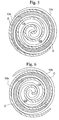
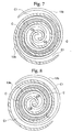
- the change in the size of the compression chambers C from the maximum volume to the minimum volume is shown by the compression chambers C in Fig. 5 ⁇ the compression chambers C in Fig. 7 ⁇ the compression chambers C0 in Fig. 5 ⁇ the compression chambers C0 in Fig. 8.
- the shapes of the compression chamber in the respective conditions during rotation are shown in Fig. 9A to Fig. 9D.
- the compression chamber becomes a variable strip shape with the width becoming narrower along the orbit axis direction.
- This width at the outer peripheral end side of the scroll compressor, becomes a lap length L1 approximately equal to the height of the wall 12b from the bottom face 12g to the upper rim 12d (or the height of the wall 13b from the bottom face 13g to the upper rim 13d), and at the central portion side, this becomes a lap length Ls ( ⁇ L1) approximately equal to the height from the bottom face 12f to the upper rim 12d (or the height of the wall 13b from the bottom face 13f to the upper rim 13d).
- the compression chamber becomes a variable strip shape with the width becoming narrower along the orbit axis direction.
- This width at the outer peripheral end side of the scroll compressor becomes a lap length Ls, and at the central portion side, this becomes a lap length Lss ( ⁇ Ls) approximately equal to the height from the bottom face 12f to the upper rim 12c (or the height of the wall 13b from the bottom face 13f to the upper rim 13c).
- the width of the compression chamber becomes a uniform lap length Lss.
- the volume change of the compression chamber is not brought about by only a reduction in the cross-section area parallel to the orbit plane as heretofore, but as shown in Fig. 9A to Fig. 9D, is also brought about by a combination of a reduction in the width in the orbit axis direction and a reduction in the cross-section area.
- the compression ratio can be improved compared to the conventional scroll compressor where the lap length of the wall pairs are constant.
- the fixed scroll 12 is pressed towards the orbiting scroll 13. Therefore, sealing of the compression chamber C can be performed without using a tip seal, and also falling off and bending of the tip seal do not occur, so that efficient compression can be performed.
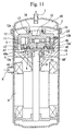
- Fig. 1 is a scroll compressor according to the present invention.
- the scroll compressor comprises a sealed housing 2, a suction pipe 23 at a bottom portion, and a discharge pipe 25 at an upper portion.
- the housing 21 comprises a driving portion 27 at an upper portion and a compressor portion 29 at the bottom portion therein.
- the driving portion 27 comprises a rotor 27a fixed on a main shaft 28 and a stator 27b fixed on the housing 21.
- the main shaft 28 is supported freely in an orbit axis direction by a main bearing 30. When current flows into the stator 27b, the main shaft 28 is supplied with power for rotating via the rotor 27a.
- the compressor portion 29 is essentially composed of a fixed scroll 31 and an orbiting scroll 32.
- the end plate of the fixed scroll 31 is fixed on the housing 21.
- a discharge port 33 of compressed fluid is provided in the center of the end plate of the orbiting scroll 32 (the present embodiment differs from the above first embodiment, a discharge port (reference symbol 15 shown in Fig. 1) is not provided on the fixed scroll 31).
- a cylindrical boss A is formed at the rear face side of the orbiting scroll 32 so as to enclose the opening of the discharge port 33 and an eccentric portion 28a of the main shaft is inserted thereinto.
- the rest of the construction of the fixed scroll 31 and the orbiting scroll 32 is the same as for the construction of the fixed scroll 12 and the orbiting scroll 13 according to the first embodiment.
- the fixed scroll 31 and the orbiting scroll 32 is provided with the step portions 42 and 43 on the end plate and comprises the walls 12b and 13b each having a stepped shape.
- a communication path 34 is provided in the orbiting axis direction so as to pass through the main shaft 26 and communicate the discharge port 33 and the discharge pipe 25.
- annular seal member 35 for separating the inside of the housing 21 into a high pressure chamber (back pressure chamber) HR and a low pressure chamber LR and sealing them is provided between the orbiting scroll 32 and the main bearing 30.
- the high pressure chamber HR is provided in the vicinity of the opening of the discharge port 33 at the rear face side of the orbiting scroll 32.
- the compression chambers C proceed towards the central portion from the outer end while maintaining the sealed condition, so that the volume is gradually reduced and the fluid compressed.
- the process of fluid compression is equal to that of the first embodiment; however, the compressed fluid is introduced into the high pressure chamber HR which is provided at the rear face side of the orbiting scroll 32 via the discharge port 33. Accordingly, the orbiting scroll 32 is pressed against the fixed scroll 31 by applying the back pressure.
- the volume change of the compression chamber is not brought about only by a reduction in the cross-section area parallel to the orbital plane as heretofore, but as shown in Fig. 9A to Fig. 9D, is also brought about by a combination of a reduction in the width in the orbit axis direction and a reduction in the cross-section area.
- the compression ratio can be improved.
- the fixed scroll 12 is pressed towards the orbiting scroll 13. Therefore, sealing of the compression chamber C can be performed without using a tip seal, and also falling off and bending of the tip seal do not occur, so that efficient compression is performed.
- Fig. 1 is a scroll compressor according to the present invention.
- the scroll compressor comprises an orbiting scroll 13' engaged with the fixed scroll 12.
- the orbiting scroll 13' is essentially composed of an end plate 13a' and the wall 13b standing on one side face of the end plate 13a'. Except for the end plate 13a', the construction of the scroll compressor 13' is the same as that of the orbiting scroll 13 according to the first embodiment.
- the end plate 13a' of the orbiting scroll 13' is provided with an annular groove 45 on the rear face side (the other side face of the end plate 13a') thereof.
- the annular groove 45 is engaged with a bearing member 46 therein.
- the bearing member 46 is provided with an annular projection 46a corresponding to the annular groove 45 and the annular projection 46a is engaged in the annular groove 45.
- the bearing member 46 is provided with a seal member 47 on sealing faces of the annular projection 46a and the annular groove 45, so that a gap between the orbiting scroll 13' and the bearing member 46 is separated into the high pressure chamber (back pressure chamber) HR' provided at the center side and the low pressure chamber LR provided at the outer side by the seal member 47.
- a communication path 48 for communicating the high pressure chamber HR' and the compression chamber C is provided in the end plate 13a'.
- a cylindrical boss A which projects into the opposite side of the annular projection 46a is provided and is inserted with the eccentric pin 9 which is provided on the upper end of the rotation shaft 9 and moves orbitally. Furthermore, the bearing member 46 is supported by the rotation prevention mechanism 10 while preventing rotation is maintained.
- the bearing member 46 moves orbitally according to rotation of the rotation shaft 9 and further movement of the bearing member 46 is transmitted to the orbiting scroll 13', so that the orbiting scroll 13' moves orbitally.
- the compression chamber C proceed towards the central portion from the outer end while maintaining the sealed condition, so that the volume is gradually reduced and the fluid compressed.
- the process of fluid compression is equal to that of the first embodiment; however, the fluid compressed is discharged from the discharge port 15 and is introduced into the high pressure chamber HR' via the communication path 48.
- the high pressure fluid introduced in the high pressure chamber HR' supplies pressure for separating the orbiting scroll 13' and the bearing member 46, and accordingly, the orbiting scroll 13' is pressed against the fixed scroll 12.
- the volume change of the compression chamber is not brought about only by a reduction in the cross-section area parallel to the orbit plane as heretofore, but as shown in Fig. 9A to Fig. 9D, is also brought about by a combination of a reduction in the width in the orbit axis direction and a reduction in the cross-section area.
- the compression ratio can be improved.
- the fixed scroll 12 is pressed towards the orbiting scroll 13'. Therefore, sealing of the compression chamber C can be performed without using a tip seal, and also falling off and bending of the tip seal do not occur, so that efficient compression is performed.
- the connecting rims 12e and 13e are formed perpendicular to the orbit plane of the orbiting scroll 13, and the connecting wall faces 12h and 13h corresponding to these are also formed perpendicular to the orbit plane.
- the connecting rims 12e and 13e, and the connecting wall faces 12h and 13h maintain a corresponding relationship with each other, then it is not necessary for these to be perpendicular to the orbital plane, and for example, these may be formed at an incline to the orbital plane.
- connecting rims 12e and 13e form a semicircle, and these may be of any shape.
- the envelope drawn by the connecting rims 12e and 13e is not a circular arc, and hence the connecting wall faces 12h and 13h are also no longer a circular arc.
- the places where the step portions 42 and 43 are formed need not each be at the same place, and these may be respectively provided at a plurality of places.
- the compressed fluid introduced into the back pressure chamber presses one scroll toward the other scroll. Accordingly, sealing of the compression chamber C is performed without using a tip seal, and also the tip seal does not fall off and bend to prevent leakage of the fluid, so that compression is efficiently performed.
Landscapes
- Engineering & Computer Science (AREA)
- Mechanical Engineering (AREA)
- General Engineering & Computer Science (AREA)
- Rotary Pumps (AREA)
Abstract
Description
Claims (5)
- A scroll compressor comprising:wherein a back pressure chamber is provided on the other side face of the end plate of at least one of the fixed scroll and the orbiting scroll, and the one scroll is pressed against the other scroll by introducing fluid which is compressed by the fixed scroll and the orbiting scroll into the back pressure chamber;a fixed scroll having a spiral wall standing on one side face of an end plate, and secured in place; andan orbiting scroll having a spiral wall standing on one side face of an end plate, and supported so as to be orbitally movable while being prevented from rotating, with the two walls engaged with each other,
a stepped shape is provided on the one side face of the end plate of at least one of the fixed scroll and the orbiting scroll, which has a high part with a height thereof which is high at a central side in a spiral direction, and a low part with a height thereof which is low at an outer peripheral end side; and
an upper rim of the wall of the other of the fixed scroll and the orbiting scroll is divided into a plurality of parts to form a stepped shape having, corresponding to the parts, a low upper rim where the height of the part is low at a central side in the spiral direction, and a high upper rim where the height of the part is high at an outer peripheral end side. - A scroll compressor according to claim 1, comprising an elastic body for pressing at least one of the fixed scroll and the orbiting scroll against the other scroll.
- A scroll compressor according to claim 1, wherein the back pressure chamber is provided on the other side face of the fixed scroll.
- A scroll compressor according to claim 1, wherein the back pressure chamber is provided on the other side face of the orbiting scroll.
- A scroll compressor according to claim 4, comprising a bearing member which performs orbital movement while engaging the other side face of the end plate of the orbiting scroll, wherein the back pressure chamber is provided between the orbiting scroll and the bearing member.
Applications Claiming Priority (3)
| Application Number | Priority Date | Filing Date | Title |
|---|---|---|---|
| JP2000188198 | 2000-06-22 | ||
| JP2000188198A JP2002005046A (en) | 2000-06-22 | 2000-06-22 | Scroll compressor |
| PCT/JP2001/005243 WO2001098661A1 (en) | 2000-06-22 | 2001-06-20 | Scrawl compressor |
Publications (3)
| Publication Number | Publication Date |
|---|---|
| EP1293674A1 true EP1293674A1 (en) | 2003-03-19 |
| EP1293674A4 EP1293674A4 (en) | 2003-08-06 |
| EP1293674B1 EP1293674B1 (en) | 2005-02-09 |
Family
ID=18688032
Family Applications (1)
| Application Number | Title | Priority Date | Filing Date |
|---|---|---|---|
| EP01941106A Expired - Lifetime EP1293674B1 (en) | 2000-06-22 | 2001-06-20 | Scroll compressor |
Country Status (7)
| Country | Link |
|---|---|
| US (1) | US20020114719A1 (en) |
| EP (1) | EP1293674B1 (en) |
| JP (1) | JP2002005046A (en) |
| KR (1) | KR100436221B1 (en) |
| CN (1) | CN1159529C (en) |
| DE (1) | DE60108871T2 (en) |
| WO (1) | WO2001098661A1 (en) |
Families Citing this family (9)
| Publication number | Priority date | Publication date | Assignee | Title |
|---|---|---|---|---|
| KR100439651B1 (en) | 2000-11-06 | 2004-07-12 | 미츠비시 쥬고교 가부시키가이샤 | Scroll compressor |
| JP2004076652A (en) * | 2002-08-19 | 2004-03-11 | Daikin Ind Ltd | Scroll type fluid machine |
| JP4939239B2 (en) * | 2007-01-22 | 2012-05-23 | 三菱重工業株式会社 | Crankshaft |
| JP5166803B2 (en) | 2007-09-13 | 2013-03-21 | 三菱重工業株式会社 | Scroll compressor |
| KR101803872B1 (en) * | 2011-01-11 | 2017-12-04 | 엘지전자 주식회사 | Scroll compressor with split type fixed scroll |
| US8579614B2 (en) * | 2011-02-04 | 2013-11-12 | Danfoss Scroll Technologies Llc | Scroll compressor with three discharge valves, and discharge pressure tap to back pressure chamber |
| KR101882713B1 (en) * | 2012-02-27 | 2018-07-27 | 엘지전자 주식회사 | Scroll compressor |
| CN107575380B (en) * | 2016-07-05 | 2020-05-05 | 艾默生环境优化技术(苏州)有限公司 | Scroll compressor having a plurality of scroll members |
| JP6661520B2 (en) * | 2016-11-30 | 2020-03-11 | 三菱重工業株式会社 | Scroll compressor and manufacturing method thereof |
Family Cites Families (12)
| Publication number | Priority date | Publication date | Assignee | Title |
|---|---|---|---|---|
| US3874827A (en) * | 1973-10-23 | 1975-04-01 | Niels O Young | Positive displacement scroll apparatus with axially radially compliant scroll member |
| US4477238A (en) * | 1983-02-23 | 1984-10-16 | Sanden Corporation | Scroll type compressor with wrap portions of different axial heights |
| US4767293A (en) * | 1986-08-22 | 1988-08-30 | Copeland Corporation | Scroll-type machine with axially compliant mounting |
| JPH04121483A (en) * | 1990-09-12 | 1992-04-22 | Toshiba Corp | Scroll type compressor |
| JPH04166689A (en) * | 1990-10-31 | 1992-06-12 | Toshiba Corp | Scroll type compressor |
| US5192202A (en) * | 1990-12-08 | 1993-03-09 | Gold Star Co., Ltd. | Scroll-type compressor with an apparatus for restraining compressed fluid from being leaked |
| JPH04311693A (en) * | 1991-04-11 | 1992-11-04 | Toshiba Corp | Scroll compressor |
| US5256044A (en) * | 1991-09-23 | 1993-10-26 | Carrier Corporation | Scroll compressor with improved axial compliance |
| JPH06101666A (en) * | 1992-09-09 | 1994-04-12 | Hitachi Ltd | Scroll compressor |
| KR960014083B1 (en) * | 1993-12-03 | 1996-10-12 | 엘지전자 주식회사 | Scroll compressor |
| JPH09112456A (en) * | 1995-10-20 | 1997-05-02 | Sanden Corp | Scroll type compressor |
| JP3608268B2 (en) * | 1995-10-23 | 2005-01-05 | 松下電器産業株式会社 | Scroll compressor |
-
2000
- 2000-06-22 JP JP2000188198A patent/JP2002005046A/en active Pending
-
2001
- 2001-06-20 KR KR10-2002-7002197A patent/KR100436221B1/en not_active Expired - Fee Related
- 2001-06-20 DE DE60108871T patent/DE60108871T2/en not_active Expired - Lifetime
- 2001-06-20 US US10/049,903 patent/US20020114719A1/en not_active Abandoned
- 2001-06-20 WO PCT/JP2001/005243 patent/WO2001098661A1/en not_active Ceased
- 2001-06-20 EP EP01941106A patent/EP1293674B1/en not_active Expired - Lifetime
- 2001-06-20 CN CNB018017401A patent/CN1159529C/en not_active Expired - Fee Related
Also Published As
| Publication number | Publication date |
|---|---|
| CN1159529C (en) | 2004-07-28 |
| EP1293674B1 (en) | 2005-02-09 |
| DE60108871T2 (en) | 2005-12-29 |
| DE60108871D1 (en) | 2005-03-17 |
| KR20020025231A (en) | 2002-04-03 |
| KR100436221B1 (en) | 2004-06-12 |
| US20020114719A1 (en) | 2002-08-22 |
| JP2002005046A (en) | 2002-01-09 |
| CN1383472A (en) | 2002-12-04 |
| EP1293674A4 (en) | 2003-08-06 |
| WO2001098661A1 (en) | 2001-12-27 |
Similar Documents
| Publication | Publication Date | Title |
|---|---|---|
| JP3509299B2 (en) | Scroll compressor | |
| US4303379A (en) | Scroll-type compressor with reduced housing radius | |
| KR970003259B1 (en) | Scroll compressor | |
| US4304535A (en) | Scroll-type compressor units with minimum housing and scroll plate radii | |
| EP2592275B1 (en) | Scroll compressor | |
| EP1205665B1 (en) | Scroll compressor | |
| WO2001098662A1 (en) | Scroll compressor | |
| JP4301713B2 (en) | Scroll compressor | |
| EP1293674B1 (en) | Scroll compressor | |
| JP3881861B2 (en) | Scroll compressor | |
| KR20170122018A (en) | Scroll compressor | |
| JP4410392B2 (en) | Scroll compressor | |
| EP3567212B1 (en) | Compressor having oldham's ring | |
| JPH0893661A (en) | Scroll fluid machinery | |
| US11053941B2 (en) | Motor-operated compressor | |
| JP4475749B2 (en) | Scroll compressor | |
| EP1225339A2 (en) | Scroll compressor | |
| EP3418572B1 (en) | Compressor having lubrication structure for thrust surface | |
| JPH08165994A (en) | Scroll type fluid device | |
| EP3990785B1 (en) | Scroll compressor | |
| JP4709402B2 (en) | Scroll compressor | |
| JP4410726B2 (en) | Scroll compressor | |
| EP2096310B1 (en) | Scroll compressor | |
| JP2002138975A (en) | Scroll compressor | |
| JPH0968174A (en) | Sealed fluid machine |
Legal Events
| Date | Code | Title | Description |
|---|---|---|---|
| PUAI | Public reference made under article 153(3) epc to a published international application that has entered the european phase |
Free format text: ORIGINAL CODE: 0009012 |
|
| 17P | Request for examination filed |
Effective date: 20020228 |
|
| AK | Designated contracting states |
Designated state(s): AT BE CH CY DE DK ES FI FR GB GR IE IT LI LU MC NL PT SE TR Kind code of ref document: A1 Designated state(s): AT BE CH CY DE DK ES FI FR GB GR IE IT LI LU MC NL PT SE TR |
|
| A4 | Supplementary search report drawn up and despatched |
Effective date: 20030620 |
|
| 17Q | First examination report despatched |
Effective date: 20031209 |
|
| RBV | Designated contracting states (corrected) |
Designated state(s): DE FR GB NL SE |
|
| GRAP | Despatch of communication of intention to grant a patent |
Free format text: ORIGINAL CODE: EPIDOSNIGR1 |
|
| RTI1 | Title (correction) |
Free format text: SCROLL COMPRESSOR |
|
| GRAS | Grant fee paid |
Free format text: ORIGINAL CODE: EPIDOSNIGR3 |
|
| GRAA | (expected) grant |
Free format text: ORIGINAL CODE: 0009210 |
|
| AK | Designated contracting states |
Kind code of ref document: B1 Designated state(s): DE FR GB NL SE |
|
| PG25 | Lapsed in a contracting state [announced via postgrant information from national office to epo] |
Ref country code: NL Free format text: LAPSE BECAUSE OF FAILURE TO SUBMIT A TRANSLATION OF THE DESCRIPTION OR TO PAY THE FEE WITHIN THE PRESCRIBED TIME-LIMIT Effective date: 20050209 |
|
| REG | Reference to a national code |
Ref country code: GB Ref legal event code: FG4D |
|
| REG | Reference to a national code |
Ref country code: IE Ref legal event code: FG4D |
|
| REF | Corresponds to: |
Ref document number: 60108871 Country of ref document: DE Date of ref document: 20050317 Kind code of ref document: P |
|
| PG25 | Lapsed in a contracting state [announced via postgrant information from national office to epo] |
Ref country code: SE Free format text: LAPSE BECAUSE OF FAILURE TO SUBMIT A TRANSLATION OF THE DESCRIPTION OR TO PAY THE FEE WITHIN THE PRESCRIBED TIME-LIMIT Effective date: 20050509 |
|
| PGFP | Annual fee paid to national office [announced via postgrant information from national office to epo] |
Ref country code: FR Payment date: 20050629 Year of fee payment: 5 |
|
| NLV1 | Nl: lapsed or annulled due to failure to fulfill the requirements of art. 29p and 29m of the patents act | ||
| ET | Fr: translation filed | ||
| PLBE | No opposition filed within time limit |
Free format text: ORIGINAL CODE: 0009261 |
|
| STAA | Information on the status of an ep patent application or granted ep patent |
Free format text: STATUS: NO OPPOSITION FILED WITHIN TIME LIMIT |
|
| 26N | No opposition filed |
Effective date: 20051110 |
|
| REG | Reference to a national code |
Ref country code: FR Ref legal event code: ST Effective date: 20070228 |
|
| PG25 | Lapsed in a contracting state [announced via postgrant information from national office to epo] |
Ref country code: FR Free format text: LAPSE BECAUSE OF NON-PAYMENT OF DUE FEES Effective date: 20060630 |
|
| PGFP | Annual fee paid to national office [announced via postgrant information from national office to epo] |
Ref country code: DE Payment date: 20190604 Year of fee payment: 19 |
|
| PGFP | Annual fee paid to national office [announced via postgrant information from national office to epo] |
Ref country code: GB Payment date: 20190619 Year of fee payment: 19 |
|
| REG | Reference to a national code |
Ref country code: DE Ref legal event code: R119 Ref document number: 60108871 Country of ref document: DE |
|
| GBPC | Gb: european patent ceased through non-payment of renewal fee |
Effective date: 20200620 |
|
| PG25 | Lapsed in a contracting state [announced via postgrant information from national office to epo] |
Ref country code: GB Free format text: LAPSE BECAUSE OF NON-PAYMENT OF DUE FEES Effective date: 20200620 |
|
| PG25 | Lapsed in a contracting state [announced via postgrant information from national office to epo] |
Ref country code: DE Free format text: LAPSE BECAUSE OF NON-PAYMENT OF DUE FEES Effective date: 20210101 |