EP1293661A2 - System and method for feeding LPG to an internal combustion engine - Google Patents
System and method for feeding LPG to an internal combustion engine Download PDFInfo
- Publication number
- EP1293661A2 EP1293661A2 EP02020303A EP02020303A EP1293661A2 EP 1293661 A2 EP1293661 A2 EP 1293661A2 EP 02020303 A EP02020303 A EP 02020303A EP 02020303 A EP02020303 A EP 02020303A EP 1293661 A2 EP1293661 A2 EP 1293661A2
- Authority
- EP
- European Patent Office
- Prior art keywords
- gpl
- fuel tank
- pump
- fuel
- injectors
- Prior art date
- Legal status (The legal status is an assumption and is not a legal conclusion. Google has not performed a legal analysis and makes no representation as to the accuracy of the status listed.)
- Withdrawn
Links
- 238000002485 combustion reaction Methods 0.000 title claims abstract description 6
- 238000000034 method Methods 0.000 title claims description 4
- 239000002828 fuel tank Substances 0.000 claims abstract description 39
- 239000000446 fuel Substances 0.000 claims abstract description 16
- 239000007788 liquid Substances 0.000 claims description 3
- 238000002347 injection Methods 0.000 claims description 2
- 239000007924 injection Substances 0.000 claims description 2
- 238000010586 diagram Methods 0.000 description 2
- 238000005516 engineering process Methods 0.000 description 2
- 238000009434 installation Methods 0.000 description 1
- 238000007789 sealing Methods 0.000 description 1
Images

Classifications
-
- F—MECHANICAL ENGINEERING; LIGHTING; HEATING; WEAPONS; BLASTING
- F02—COMBUSTION ENGINES; HOT-GAS OR COMBUSTION-PRODUCT ENGINE PLANTS
- F02M—SUPPLYING COMBUSTION ENGINES IN GENERAL WITH COMBUSTIBLE MIXTURES OR CONSTITUENTS THEREOF
- F02M21/00—Apparatus for supplying engines with non-liquid fuels, e.g. gaseous fuels stored in liquid form
- F02M21/02—Apparatus for supplying engines with non-liquid fuels, e.g. gaseous fuels stored in liquid form for gaseous fuels
- F02M21/0218—Details on the gaseous fuel supply system, e.g. tanks, valves, pipes, pumps, rails, injectors or mixers
- F02M21/0221—Fuel storage reservoirs, e.g. cryogenic tanks
-
- F—MECHANICAL ENGINEERING; LIGHTING; HEATING; WEAPONS; BLASTING
- F02—COMBUSTION ENGINES; HOT-GAS OR COMBUSTION-PRODUCT ENGINE PLANTS
- F02D—CONTROLLING COMBUSTION ENGINES
- F02D19/00—Controlling engines characterised by their use of non-liquid fuels, pluralities of fuels, or non-fuel substances added to the combustible mixtures
- F02D19/02—Controlling engines characterised by their use of non-liquid fuels, pluralities of fuels, or non-fuel substances added to the combustible mixtures peculiar to engines working with gaseous fuels
- F02D19/021—Control of components of the fuel supply system
- F02D19/022—Control of components of the fuel supply system to adjust the fuel pressure, temperature or composition
-
- F—MECHANICAL ENGINEERING; LIGHTING; HEATING; WEAPONS; BLASTING
- F02—COMBUSTION ENGINES; HOT-GAS OR COMBUSTION-PRODUCT ENGINE PLANTS
- F02D—CONTROLLING COMBUSTION ENGINES
- F02D19/00—Controlling engines characterised by their use of non-liquid fuels, pluralities of fuels, or non-fuel substances added to the combustible mixtures
- F02D19/02—Controlling engines characterised by their use of non-liquid fuels, pluralities of fuels, or non-fuel substances added to the combustible mixtures peculiar to engines working with gaseous fuels
- F02D19/026—Measuring or estimating parameters related to the fuel supply system
- F02D19/027—Determining the fuel pressure, temperature or volume flow, the fuel tank fill level or a valve position
-
- F—MECHANICAL ENGINEERING; LIGHTING; HEATING; WEAPONS; BLASTING
- F02—COMBUSTION ENGINES; HOT-GAS OR COMBUSTION-PRODUCT ENGINE PLANTS
- F02M—SUPPLYING COMBUSTION ENGINES IN GENERAL WITH COMBUSTIBLE MIXTURES OR CONSTITUENTS THEREOF
- F02M21/00—Apparatus for supplying engines with non-liquid fuels, e.g. gaseous fuels stored in liquid form
- F02M21/02—Apparatus for supplying engines with non-liquid fuels, e.g. gaseous fuels stored in liquid form for gaseous fuels
- F02M21/0203—Apparatus for supplying engines with non-liquid fuels, e.g. gaseous fuels stored in liquid form for gaseous fuels characterised by the type of gaseous fuel
- F02M21/0209—Hydrocarbon fuels, e.g. methane or acetylene
- F02M21/0212—Hydrocarbon fuels, e.g. methane or acetylene comprising at least 3 C-Atoms, e.g. liquefied petroleum gas [LPG], propane or butane
-
- F—MECHANICAL ENGINEERING; LIGHTING; HEATING; WEAPONS; BLASTING
- F02—COMBUSTION ENGINES; HOT-GAS OR COMBUSTION-PRODUCT ENGINE PLANTS
- F02M—SUPPLYING COMBUSTION ENGINES IN GENERAL WITH COMBUSTIBLE MIXTURES OR CONSTITUENTS THEREOF
- F02M21/00—Apparatus for supplying engines with non-liquid fuels, e.g. gaseous fuels stored in liquid form
- F02M21/02—Apparatus for supplying engines with non-liquid fuels, e.g. gaseous fuels stored in liquid form for gaseous fuels
- F02M21/0218—Details on the gaseous fuel supply system, e.g. tanks, valves, pipes, pumps, rails, injectors or mixers
- F02M21/0245—High pressure fuel supply systems; Rails; Pumps; Arrangement of valves
-
- F—MECHANICAL ENGINEERING; LIGHTING; HEATING; WEAPONS; BLASTING
- F02—COMBUSTION ENGINES; HOT-GAS OR COMBUSTION-PRODUCT ENGINE PLANTS
- F02M—SUPPLYING COMBUSTION ENGINES IN GENERAL WITH COMBUSTIBLE MIXTURES OR CONSTITUENTS THEREOF
- F02M37/00—Apparatus or systems for feeding liquid fuel from storage containers to carburettors or fuel-injection apparatus; Arrangements for purifying liquid fuel specially adapted for, or arranged on, internal-combustion engines
- F02M37/04—Feeding by means of driven pumps
- F02M37/08—Feeding by means of driven pumps electrically driven
- F02M37/10—Feeding by means of driven pumps electrically driven submerged in fuel, e.g. in reservoir
-
- Y—GENERAL TAGGING OF NEW TECHNOLOGICAL DEVELOPMENTS; GENERAL TAGGING OF CROSS-SECTIONAL TECHNOLOGIES SPANNING OVER SEVERAL SECTIONS OF THE IPC; TECHNICAL SUBJECTS COVERED BY FORMER USPC CROSS-REFERENCE ART COLLECTIONS [XRACs] AND DIGESTS
- Y02—TECHNOLOGIES OR APPLICATIONS FOR MITIGATION OR ADAPTATION AGAINST CLIMATE CHANGE
- Y02T—CLIMATE CHANGE MITIGATION TECHNOLOGIES RELATED TO TRANSPORTATION
- Y02T10/00—Road transport of goods or passengers
- Y02T10/10—Internal combustion engine [ICE] based vehicles
- Y02T10/30—Use of alternative fuels, e.g. biofuels
Definitions
- the present invention relates to GPL fuel injection systems for internal combustion engines.
- fuel systems of this type include:
- the object of this invention is that of realizing a fuel system and method that, on the one hand, ensures that the fuel pump delivers the correct head and the correct flow rate under all engine running conditions, whilst on the other hand also ensuring a long operating life for the pump itself.
- the object of the invention is a GPL fuel system having all of the above-indicated characteristics and also characterized in that the said system includes electronic means of pump control, a pressure sensor and/or temperature sensor inside the fuel tank, and by the fact that the said electronic means are programmed to:
- a typically used pump in a fuel system of this type When fed with a 12-volt supply, a typically used pump in a fuel system of this type is capable of guaranteeing a flow rate of 120 l/hr.
- a chopper control of the voltage can therefore be applied in such conditions to guarantee, on the one hand, feeding the injectors at an adequate flow rate and, on the other, maintaining the current absorbed by the pump at lower average values that prolong the useful lifetime of the motor-pump group.
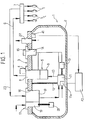
- item 1 indicates a GPL fuel tank in its entirety, realized according to known technology, for delivering GPL to a number of injectors I associated with the various cylinders of the engine.
- the fuel tank 1 presents a hollow structure 2, realized so as to guarantee sealing under the planned running conditions for the type of installation under discussion.
- the hollow structure 2 presents an upper aperture closed by a service flange 3 carrying various connecting elements linking the fuel tank to the fuel system.
- the fuel tank 1 realized according to known technology presents a first through opening 4, through which the structure of a group 5 is mounted, the latter being connected to a line 6 for delivering GPL to an inlet manifold or rail 7, which distributes the GPL to the various injectors I.
- the group 5 includes a solenoid shut-off valve 8, destined to close itself and cut the fuel tank off to the outside in predetermined emergency conditions, together with a flow restrictor valve 9.
- the group 5 receives GPL via the line 10 from a pump 11 driven by an electric motor 11a, the structure of which is connected to the service flange 3 via a connection element 12. Notwithstanding, mounting of the pump 11 can also be accomplished in any other manner.
- a GPL level sensor device 13 is also connected to the structure of the pump 11.
- the electrical power supply to the solenoid valve 8, the pump 11 and the sensor 13 is provided via an electrical connector 14, which is mounted through a through opening 15 of the service flange 3.
- the latter also presents an additional through opening 16, inside which a group 17, including two valves 18 and 19, is mounted.
- Valve 18 is a return valve, which is connected to a line 20 for returning GPL delivered in excess to the rail 7 back to the fuel tank.
- Valve 19 is the valve used for filling the fuel tank and is associated with an additional level sensor 21.
- a safety valve 22 is also associated with the flange 3 to prevent pressure inside the fuel tank exceeding a predetermined threshold.
- Figure 1 shows a traditional fuel tank configuration in which the flange 3 presents through openings, through which the various above-described components pass.
- This invention could also be embodied using a fuel tank having an innovative structure that formed the object of previous Italian patent application n° T02001A000360, filed by the same Applicant, in which at least some of the aforementioned components are fixed to the lower surface of the plate, without passing through it.
- operation of the electric motor 11a driving the pump 11 is controlled by electronic means of control 40 (schematically illustrated in Figure 1) on the basis of the signal received from a pressure and/or temperature sensor 41.
- the sensor 41 has been schematically illustrated as being located inside the fuel tank, Naturally, a different location for the sensor could also be provided.
- the pump when the temperature of the GPL in the fuel tank is below 0°C or above 80°C, the pump is kept constantly running, as described in the foregoing, thereby guaranteeing the correct head and the correct flow-rate of GPL under all operating conditions.
- chopper control is performed on the supply voltage to the pump according to that illustrated in the diagram shown in Figure 2.
- the upper part indicates the variation in supply voltage.
- the voltage in each time period T, the voltage is only kept at its supply value for a fraction of this period, while the voltage drops to zero in the remaining part.
- the supply current varies cyclically between a minimum value and a maximum value, maintaining a relatively low average value that permits the useful life of the pump's drive motor to be extended.
Landscapes
- Engineering & Computer Science (AREA)
- Chemical & Material Sciences (AREA)
- Combustion & Propulsion (AREA)
- Mechanical Engineering (AREA)
- General Engineering & Computer Science (AREA)
- Chemical Kinetics & Catalysis (AREA)
- General Chemical & Material Sciences (AREA)
- Oil, Petroleum & Natural Gas (AREA)
- Electrical Control Of Air Or Fuel Supplied To Internal-Combustion Engine (AREA)
- Output Control And Ontrol Of Special Type Engine (AREA)
Abstract
Description
- a GPL fuel tank,
- a number of injectors associated with the engine's cylinders, for injecting liquid GPL into these cylinders,
- a fuel manifold or rail for feeding GPL to the said injectors,
- a line for feeding GPL from the fuel tank to the said rail,
- a return line for returning GPL fed in excess to the injectors back to the fuel tank,
- sensors for the level of GPL in the fuel tank,
- a pump immersed in the fuel tank for delivering GPL via the GPL fuel line, and
- an electric motor driving the pump.
- keep the pump constantly running when the temperature in the fuel tank is below 0°C or above 80°C,
- realize a chopper control on the voltage supply to the electric motor driving the pump when the temperature in the fuel tank is between 0°C and 80°C.
- Figure 1 is a schematic view of a GPL fuel system modified according to the precepts of the invention, and
- Figure 2 illustrates the voltage variation diagrams of the power supply to the electric motor driving the pump during chopper-control in the normal running phases.
Claims (2)
- A GPL fuel injection system for an internal combustion engine, including:characterized in that the said system includes electronic means of control for the electric motor driving the pump, as well as a pressure and/or temperature sensor (41) inside the fuel tank, and by the fact that the said electronic means of control are programmed to:a GPL fuel tank (1),a number of GPL injectors (I) associated with the engine's cylinders, for injecting liquid GPL into these cylinders,a manifold or rail (7) for feeding GPL to the said injectors (I),a line (6) for feeding GPL from the fuel tank (1) to the said rail (7),a return line (20) for returning GPL fed in excess to the injectors (I) back to the fuel tank (1),sensors (13) for the level of GPL in the fuel tank,a pump (11) immersed in the fuel tank (1) for delivering GPL via the GPL fuel line (6), andan electric motor (11a) driving the pump (11),keep the pump (11) constantly running when the temperature in the fuel tank is below 0°C or above 80°C,realize a chopper control on the voltage supply to the electric motor (11a) driving the pump (11) when the temperature in the fuel tank is between 0°C and 80°C.
- A GPL fuel distribution process in an internal combustion engine, in which the following are arranged:characterized in that the said pump (11) is kept constantly running when the temperature in the fuel tank is below 0°C or above 80°C, and by the fact that a chopper control is applied to the supply voltage of the electric motor (11a) driving the pump when the temperature in the fuel tank is between the two said values.a GPL fuel tank (1),a number of GPL injectors (I) associated with the engine's cylinders,a manifold or rail (7) for feeding GPL to the said injectors (I),a line (6) for feeding GPL from the fuel tank (1) to the said rail (7),a return line (20) for returning GPL fed in excess to the injectors (I) back to the fuel tank (1),sensors (13) for the level of GPL in the fuel tank,a pump (11) immersed in the fuel tank (1) for delivering GPL via the GPL fuel line (6), andan electric motor (11a) driving the pump (11),
Applications Claiming Priority (2)
| Application Number | Priority Date | Filing Date | Title |
|---|---|---|---|
| ITTO20010887 | 2001-09-18 | ||
| IT2001TO000887A ITTO20010887A1 (en) | 2001-09-18 | 2001-09-18 | SYSTEM AND PROCEDURE FOR SUPPLYING LPG TO AN INTERNAL COMBUSTION ENGINE. |
Publications (2)
| Publication Number | Publication Date |
|---|---|
| EP1293661A2 true EP1293661A2 (en) | 2003-03-19 |
| EP1293661A3 EP1293661A3 (en) | 2005-12-21 |
Family
ID=11459202
Family Applications (1)
| Application Number | Title | Priority Date | Filing Date |
|---|---|---|---|
| EP02020303A Withdrawn EP1293661A3 (en) | 2001-09-18 | 2002-09-11 | System and method for feeding LPG to an internal combustion engine |
Country Status (4)
| Country | Link |
|---|---|
| US (1) | US6748931B2 (en) |
| EP (1) | EP1293661A3 (en) |
| CA (1) | CA2403802A1 (en) |
| IT (1) | ITTO20010887A1 (en) |
Cited By (1)
| Publication number | Priority date | Publication date | Assignee | Title |
|---|---|---|---|---|
| US10047340B2 (en) | 2002-05-24 | 2018-08-14 | Advanced Cell Technology, Inc. | Bank of stem cells for producing cells for transplantation having HLA antigens matching those of transplant recipients, and methods for making and using such a stem cell bank |
Families Citing this family (7)
| Publication number | Priority date | Publication date | Assignee | Title |
|---|---|---|---|---|
| US6901971B2 (en) * | 2001-01-10 | 2005-06-07 | Entegris, Inc. | Transportable container including an internal environment monitor |
| EP2156043A4 (en) * | 2007-05-23 | 2015-08-26 | Interlocking Buildings Pty Ltd | A method of manufacturing and installation of high pressure liquid lpg fuel supply and dual or mixed fuel supply systems |
| US8443785B2 (en) * | 2010-09-10 | 2013-05-21 | GM Global Technology Operations LLC | Liquefied petroleum gas (LPG) pump control systems and methods |
| PL2788215T3 (en) * | 2011-12-07 | 2020-06-15 | Agility Fuel Systems Llc | Systems and methods for monitoring and controlling fuel systems |
| KR101349509B1 (en) * | 2012-05-24 | 2014-01-09 | 현대자동차주식회사 | LPI Fuel System and Return Fuel Minimum Method thereof |
| US9347376B2 (en) | 2013-04-24 | 2016-05-24 | General Electric Company | Liquified fuel backup fuel supply for a gas turbine |
| US9650982B2 (en) | 2015-06-02 | 2017-05-16 | GM Global Technology Operations LLC | Liquefied petroleum gas butane composition determination systems and methods |
Family Cites Families (6)
| Publication number | Priority date | Publication date | Assignee | Title |
|---|---|---|---|---|
| US5367999A (en) * | 1993-04-15 | 1994-11-29 | Mesa Environmental Ventures Limited Partnership | Method and system for improved fuel system performance of a gaseous fuel engine |
| US5343847A (en) * | 1993-09-13 | 1994-09-06 | Pacer Industries, Inc. | Electronic gaseous fuel injection system |
| US5590631A (en) * | 1994-01-14 | 1997-01-07 | Walbro Corporation | Fuel system accumulator |
| ES2105917T3 (en) * | 1995-02-03 | 1997-10-16 | Fiat Ricerche | INTERNAL COMBUSTION ENGINE ADAPTED TO OPERATE SELECTIVELY WITH GASOLINE INJECTION OR WITH LPG. |
| US6314947B1 (en) * | 1999-10-13 | 2001-11-13 | Walbro Corporation | Fuel delivery system |
| US6250290B1 (en) * | 2000-04-06 | 2001-06-26 | Transportation Design & Manufacturing Co. | Cooled LPG fuel rail |
-
2001
- 2001-09-18 IT IT2001TO000887A patent/ITTO20010887A1/en unknown
-
2002
- 2002-09-11 EP EP02020303A patent/EP1293661A3/en not_active Withdrawn
- 2002-09-17 CA CA002403802A patent/CA2403802A1/en not_active Abandoned
- 2002-09-17 US US10/244,675 patent/US6748931B2/en not_active Expired - Fee Related
Cited By (1)
| Publication number | Priority date | Publication date | Assignee | Title |
|---|---|---|---|---|
| US10047340B2 (en) | 2002-05-24 | 2018-08-14 | Advanced Cell Technology, Inc. | Bank of stem cells for producing cells for transplantation having HLA antigens matching those of transplant recipients, and methods for making and using such a stem cell bank |
Also Published As
| Publication number | Publication date |
|---|---|
| US20030051711A1 (en) | 2003-03-20 |
| CA2403802A1 (en) | 2003-03-18 |
| EP1293661A3 (en) | 2005-12-21 |
| ITTO20010887A1 (en) | 2003-03-18 |
| ITTO20010887A0 (en) | 2001-09-18 |
| US6748931B2 (en) | 2004-06-15 |
Similar Documents
| Publication | Publication Date | Title |
|---|---|---|
| USRE45159E1 (en) | System for supply of LPG/ammonia for direct-injection petrol or diesel engines | |
| JP3972317B2 (en) | Pressurized fluid supply regulator for pressurized fluid accumulator | |
| FI106395B (en) | Electronic fuel injection system for a compression ignition engine | |
| EP2029882B1 (en) | Method and apparatus for supplying fuel of lpg car having lpi system | |
| US6877488B2 (en) | Vehicle fuel management system | |
| EP2235352B1 (en) | System and method for preventing overheating of a fuel pump | |
| US7370638B2 (en) | Fuel injection control system ensuring steady balance in pressure in accumulator | |
| KR20050111576A (en) | Dosing pump assembly | |
| JPH02298660A (en) | Fuel feed system for internal combustion engine | |
| US6748931B2 (en) | System and method for feeding LPG to an internal combustion engine | |
| EP1234971A2 (en) | Control method | |
| CN100416075C (en) | Method and device for operating a diesel engine using a fuel containing vegetable oil or recycled vegetable oil | |
| JP2010537106A (en) | Method and apparatus for injecting fuel into a combustion chamber of an internal combustion engine | |
| JPH09209843A (en) | Injection valve device | |
| EP3156621A1 (en) | Remote fluid supply for an engine | |
| JP7033616B2 (en) | A system that adapts an internal combustion engine to be driven by gas-phase gaseous fuel and liquid-phase gaseous fuel. | |
| JPH08232790A (en) | Fuel supply device for internal combustion engine | |
| JP2002539376A (en) | Fuel injection pump and snubber valve assembly | |
| SE525601C2 (en) | Equipment is for supply with heating of reduction medium from tank to exhaust gas conduit of internal combustion engine | |
| EP1435450B1 (en) | A system and method for feeding LPG by injection for an internal combustion engine | |
| JP2001173534A (en) | Fuel feeding device and fuel pump | |
| KR100213157B1 (en) | Pneumatic fuel system | |
| EP3249206B1 (en) | System for adapting an internal combustion engine to be powered by gaseous fuel in gas phase and by gaseous fuel in liquid phase | |
| JPH09324713A (en) | Electronically controlled fuel supplier for outboard motor | |
| KR19980046184A (en) | Auxiliary Fuel Storage |
Legal Events
| Date | Code | Title | Description |
|---|---|---|---|
| PUAI | Public reference made under article 153(3) epc to a published international application that has entered the european phase |
Free format text: ORIGINAL CODE: 0009012 |
|
| AK | Designated contracting states |
Kind code of ref document: A2 Designated state(s): AT BE BG CH CY CZ DE DK EE ES FI FR GB GR IE IT LI LU MC NL PT SE SK TR Designated state(s): AT BE BG CH CY CZ DE DK EE ES FI FR GB GR IE IT LI LU MC NL PT SE SK TR |
|
| AX | Request for extension of the european patent |
Extension state: AL LT LV MK RO SI |
|
| PUAL | Search report despatched |
Free format text: ORIGINAL CODE: 0009013 |
|
| AK | Designated contracting states |
Kind code of ref document: A3 Designated state(s): AT BE BG CH CY CZ DE DK EE ES FI FR GB GR IE IT LI LU MC NL PT SE SK TR |
|
| AX | Request for extension of the european patent |
Extension state: AL LT LV MK RO SI |
|
| 17P | Request for examination filed |
Effective date: 20060203 |
|
| AKX | Designation fees paid |
Designated state(s): AT BE BG CH CY CZ DE DK EE ES FI FR GB GR IE IT LI LU MC NL PT SE SK TR |
|
| 17Q | First examination report despatched |
Effective date: 20060529 |
|
| GRAP | Despatch of communication of intention to grant a patent |
Free format text: ORIGINAL CODE: EPIDOSNIGR1 |
|
| STAA | Information on the status of an ep patent application or granted ep patent |
Free format text: STATUS: THE APPLICATION IS DEEMED TO BE WITHDRAWN |
|
| 18D | Application deemed to be withdrawn |
Effective date: 20080401 |