EP1293650A2 - Metal substrate - Google Patents
Metal substrate Download PDFInfo
- Publication number
- EP1293650A2 EP1293650A2 EP02019895A EP02019895A EP1293650A2 EP 1293650 A2 EP1293650 A2 EP 1293650A2 EP 02019895 A EP02019895 A EP 02019895A EP 02019895 A EP02019895 A EP 02019895A EP 1293650 A2 EP1293650 A2 EP 1293650A2
- Authority
- EP
- European Patent Office
- Prior art keywords
- corrugated foil
- honeycomb structure
- foil
- metal substrate
- outer casing
- Prior art date
- Legal status (The legal status is an assumption and is not a legal conclusion. Google has not performed a legal analysis and makes no representation as to the accuracy of the status listed.)
- Granted
Links
Images




Classifications
-
- F—MECHANICAL ENGINEERING; LIGHTING; HEATING; WEAPONS; BLASTING
- F01—MACHINES OR ENGINES IN GENERAL; ENGINE PLANTS IN GENERAL; STEAM ENGINES
- F01N—GAS-FLOW SILENCERS OR EXHAUST APPARATUS FOR MACHINES OR ENGINES IN GENERAL; GAS-FLOW SILENCERS OR EXHAUST APPARATUS FOR INTERNAL-COMBUSTION ENGINES
- F01N3/00—Exhaust or silencing apparatus having means for purifying, rendering innocuous, or otherwise treating exhaust
- F01N3/08—Exhaust or silencing apparatus having means for purifying, rendering innocuous, or otherwise treating exhaust for rendering innocuous
- F01N3/10—Exhaust or silencing apparatus having means for purifying, rendering innocuous, or otherwise treating exhaust for rendering innocuous by thermal or catalytic conversion of noxious components of exhaust
- F01N3/24—Exhaust or silencing apparatus having means for purifying, rendering innocuous, or otherwise treating exhaust for rendering innocuous by thermal or catalytic conversion of noxious components of exhaust characterised by constructional aspects of converting apparatus
- F01N3/28—Construction of catalytic reactors
- F01N3/2803—Construction of catalytic reactors characterised by structure, by material or by manufacturing of catalyst support
- F01N3/2807—Metal other than sintered metal
- F01N3/281—Metallic honeycomb monoliths made of stacked or rolled sheets, foils or plates
- F01N3/2814—Metallic honeycomb monoliths made of stacked or rolled sheets, foils or plates all sheets, plates or foils being corrugated
-
- F—MECHANICAL ENGINEERING; LIGHTING; HEATING; WEAPONS; BLASTING
- F01—MACHINES OR ENGINES IN GENERAL; ENGINE PLANTS IN GENERAL; STEAM ENGINES
- F01N—GAS-FLOW SILENCERS OR EXHAUST APPARATUS FOR MACHINES OR ENGINES IN GENERAL; GAS-FLOW SILENCERS OR EXHAUST APPARATUS FOR INTERNAL-COMBUSTION ENGINES
- F01N2260/00—Exhaust treating devices having provisions not otherwise provided for
- F01N2260/10—Exhaust treating devices having provisions not otherwise provided for for avoiding stress caused by expansions or contractions due to temperature variations
-
- F—MECHANICAL ENGINEERING; LIGHTING; HEATING; WEAPONS; BLASTING
- F01—MACHINES OR ENGINES IN GENERAL; ENGINE PLANTS IN GENERAL; STEAM ENGINES
- F01N—GAS-FLOW SILENCERS OR EXHAUST APPARATUS FOR MACHINES OR ENGINES IN GENERAL; GAS-FLOW SILENCERS OR EXHAUST APPARATUS FOR INTERNAL-COMBUSTION ENGINES
- F01N2330/00—Structure of catalyst support or particle filter
- F01N2330/30—Honeycomb supports characterised by their structural details
- F01N2330/32—Honeycomb supports characterised by their structural details characterised by the shape, form or number of corrugations of plates, sheets or foils
- F01N2330/321—Honeycomb supports characterised by their structural details characterised by the shape, form or number of corrugations of plates, sheets or foils with two or more different kinds of corrugations in the same substrate
-
- Y—GENERAL TAGGING OF NEW TECHNOLOGICAL DEVELOPMENTS; GENERAL TAGGING OF CROSS-SECTIONAL TECHNOLOGIES SPANNING OVER SEVERAL SECTIONS OF THE IPC; TECHNICAL SUBJECTS COVERED BY FORMER USPC CROSS-REFERENCE ART COLLECTIONS [XRACs] AND DIGESTS
- Y10—TECHNICAL SUBJECTS COVERED BY FORMER USPC
- Y10T—TECHNICAL SUBJECTS COVERED BY FORMER US CLASSIFICATION
- Y10T428/00—Stock material or miscellaneous articles
- Y10T428/12—All metal or with adjacent metals
- Y10T428/1234—Honeycomb, or with grain orientation or elongated elements in defined angular relationship in respective components [e.g., parallel, inter- secting, etc.]
Definitions
- the present invention relates to a structure of a metal substrate installed in an exhaust system of a vehicle.
- a metal substrate for carrying a catalyst for oxidizing or reducing the harmful components in an exhaust gas is installed.
- Many metal substrates have been up to now proposed in which a large corrugated foil having relatively large corrugations and a small corrugated foil having small corrugations are overlapped and wound alternately.
- This metal substrate has a number of cells formed between each corrugated foil to keep a contact area with the exhaust gas.
- the corrugated foil may be typically made from a foil material of 20Cr-5Al-Fe having a thickness of 30 to 50 ⁇ m in consideration of resistance to oxidation.
- the corrugated foils are connected by brazing of nickel (Ni) so that the cell density is 600 cells/square inches at maximum.
- a metal substrate having an outer casing and a honeycomb structure formed by overlapping and winding a large corrugated foil and a small corrugated foil, the honeycomb structure held in the outer casing.
- the large corrugated foil and the small corrugated foil have thickness in a range of 18 ⁇ m to 22 ⁇ m.
- the honeycomb structure has cell density in a range of 810 cells/square inches to 990 cells/square inches.
- the large. corrugated foil and the small corrugated foil in the honeycomb structure are connected by diffused junction.
- the large corrugated foil has a wave height in a range of 0.76 mm to 0.86 mm and a pitch in a range of 1.66 mm to 1.76 mm.
- the small corrugated foil has a wave height in a range of 0.05 mm to 0.18 mm and a pitch in a range of 1.29 mm to 1.39 mm.
- the small corrugated foil is overlapped and wound around an outermost circumference of the honeycomb structure multiple times.
- the honeycomb structure is brazed with an inner circumferential face of the outer casing by a brazing foil disposed in an area spaced away a predetermined distance from a back end face of the honeycomb structure on a rear-half side in a flow direction of exhaust gas.
- the outer casing is formed with a radially outwardly swollen bead around the entire circumference of the outer casing on an opposite side to the rear end face of the honeycomb structure, with the brazing foil before brazing sandwiched.
- Fig. 1 is a view illustrating a metal substrate according to an embodiment of the present invention.
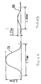
- Fig. 2 is a diagram showing combination shapes of a large corrugated foil and a small corrugated foil in this embodiment.
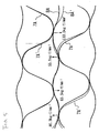
- Fig. 3 is a view showing a thermal deformation state and a produced stress in combination of the corrugated foils as shown in Fig. 2.
- Fig. 4 is a diagram showing combination shapes of other corrugated foils.
- Fig. 5 is a view showing a thermal deformation state and a produced stress in the combination of corrugated foils as shown in Fig. 4.
- Fig. 6 is a diagram showing a variation of average produced stress when wave height of the small corrugated foil is changed.
- Fig. 7 is a view showing a thermal deformation state and a produced stress in the combination of a large corrugated foil and a flat plate as shown in Fig. 4.
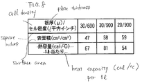
- Fig. 8 is a table showing variations in the surface area and heat capacity with respect to the plate thickness of corrugated foil and cell density thereof.
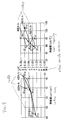
- Fig. 9 is a graph showing evaluations for an actual vehicle in the purification of exhaust gas.
- Fig. 1 is a structure view of a metal substrate according to an embodiment of the present invention, in which an upper half part above an axial center line as indicated by a dashed line is a longitudinal section and a lower half part is an outside face.
- An outer casing 2 is made of stainless material (SUS) having a thickness of 2mm and formed into a cylindrical shape having a length of about 115mm and an outer diameter of 106mm. At a central position of the outer casing 2 in the axial (longitudinal) direction, a bead 3 swollen radially outwardly having about 10 mm in width is formed around the entire circumference.
- SUS stainless material
- a honeycomb structure 5 having a length of 110m is inserted into the inside of the outer casing 2. Both ends of the honeycomb structure 5 is retracted inside the end faces of the outer casing 2. To prevent damage on both end faces of the honeycomb structure 5.
- the outer circumferential face of the honeycomb structure 5 is brazed with the inner circumferential face of the outer casing 2 on the rear half side of the outer casing 2 in a direction of exhaust gas stream.
- the brazing is performed while a brazing foil material 10 having a width of about 25 mm is placed around the entire circumference closer to the bead 3 centrally disposed.
- a gap D of 17 mm is provided between a rear end face of the honeycomb structure 5 and the brazing foil material 10.
- the honeycomb structure 5 is formed like a cylinder by overlapping and winding a large corrugated foil 7 having large corrugations and a small corrugated foil 8 having small corrugations alternately.
- the large corrugated foil 7 and the small corrugated foil 8 are formed from a foil material having a plate thickness of 20 ⁇ m.
- the large corrugated foil 7 and the small corrugated foil 8 are connected at contact points by diffused junction after being overlapped and wound. Though not specifically illustrated, the small corrugated foil 8 is overlapped and wound, for example, three times, around the outermost circumference.
- the catalyst is carried on a surface of each corrugated foil 7, 8.
- the large corrugated foil 7 and the small corrugated foil 8 may be formed from a foil material having a plate thickness in a range of 18 ⁇ m to 22 ⁇ m (tolerance).
- the large corrugated foil 7 and the small corrugated foil 8 are made of Cr of 19.0 to 21.0(wt%), Al of 5.0 to 6.0(wt%), Mn of 1.00 or less (wt%), Si of 1.00 or less (wt%), C of 0.01. or less (wt%), P of 0.04 or less (wt%), S of 0.03 or less (wt%), La of 0.06 to 0.12 (wt%.), and Fe for the remaining.
- a wave shape of the large corrugated foil 7 has a wave height of 0.81mm and a pitch of 1.71mm, as shown in Fig. 2A
- that of the small corrugated foil 8 has a wave height of 0.11mm and a pitch of 1.34mm, as shown in Fig. 2B.
- the cell density may be in a range of 810 cells/square inches to 9.90 cells/square inches.
- the dimensional tolerance of wave height and pitch of the large corrugated foil 7 is ⁇ 0.05mm
- the dimensional tolerance of pitch of the small corrugated foil 8 is ⁇ 0.05mm. That is, the large corrugated foil 7 has a wave height from 0.76 to 0.86mm and a pitch from 1.66 to 1.76mm, and the small corrugated foil 8 has a pitch from 1.29 to 1.39mm.
- Fig. 3 illustrates a state where the large corrugated foil 7 and the small corrugated foil 8 are overlapped in the solid line.
- the honeycomb structure 5 is subjected to a temperature of 900°, a case is simulated in which thermal expansion arises in a direction where the greatest stress is possibly produced by this heat, namely, adjacent large corrugated foils 7, 7 are opposed, as indicated by the broken line.
- the produced stress at the contact point in the simulation is varied depending-on the contact position between the large corrugated foil 7' and the small corrugated foil 8', after the thermal expansion.
- the produced stress at the contact point is 35.6kg ⁇ f/mm 2 , 35.2kg ⁇ f/mm 2 , 13.4kg ⁇ f/mm 2 , and 52.5kg ⁇ f/mm 2 .
- An average value (average produced stress) thereof is as low as 34kg ⁇ f/mm 2 , as shown in Fig. 3.
- the produced stresses at the contact points between the large corrugated foil 7' and the small corrugated foil 8A' after expansion is 80.9kg ⁇ f/mm 2 , 65.5kg ⁇ f/mm 2 , 55.1kg ⁇ f/mm 2 , and 134.0kg ⁇ f/mm 2 , its average value being 84kg ⁇ f/mm 2 .
- Fig. 6 is a graph showing how the average produced stress is changed when the wave height is changed while the pitch of the small corrugated foil 8 is kept 1.34mm.
- the tensile strength of the foil material for each corrugated foil 7, 8 at a temperature of 900°C is 2.2kg ⁇ f/mm 2 (220kg ⁇ f/cm 2 ), which is defined as the tolerance limit value.
- the average produced stress is set at a level of the tolerance limit value multiplied by a safety factor of 0.5, whereby the wave height of the small corrugated foil 8 is preferably from about 0.05mm to 0.18mm, as shown in Fig. 6.
- Fig. 8 shows the variations in the surface area and the heat capacity with respect to the settings of the plate thickness and the cell density for the corrugated foils (7, 8).
- the surface area is increased from 47cm 2 /cm 3 to 58cm 2 /cm 3
- the heat capacity is increased from 67 cal/°C to 81 cal/°C.
- the surface area is increased by about 26% from 47cm 2 /cm 3 to 59cm 2 /cm 3 , and the heat capacity is decreased by 20% from 67 cal/°C to 54 cal/°C.
- the metal substrate 1 in which the honeycomb structure 5 including the large corrugated foil 7 and the small corrugated foil 8 over lapped and wound is held within the outer casing 2.
- the plate thickness of both the corrugated foils is in a range of 18 ⁇ m to 22 ⁇ m, preferably 20 ⁇ m
- the cell density of the honeycomb structure is in a range of 810 cells/square inches to 990 cells/square inches, preferably 900 cells/square inches.
- the surface area of the catalyst contact with the exhaust gas is conspicuously increased and the heat capacity is decreased. Accordingly, the increased surface area and the decreased heat capacity are involved to remarkably enhance the exhaust emission purification performance from the early stage of starting the operation, and make lighter the carrier.
- the large corrugated foil 7 has a wave height of 0.81mm and a pitch of 1.71mm
- the small corrugated foil 8 has a predetermined wave height (about 0.05mm to 0.18mm, particularly 0.11mm) and a pitch of 1.34mm, whereby the produced stress upon thermal expansion is at lower level, and the high temperature durability is further improved.
- the brazing between the outer casing 2 and the honeycomb structure 5 is made near the center with the gap D from the back end of the honeycomb structure 5 on the rear-half side of the outer casing 2 in a flow direction of exhaust gas and both the outer casing 2 and the honeycomb structure 5 are at substantially even temperature and connected in the area not subjected to the heat radiation on the back end face. Therefore the thermal stress between the outer casing 2 and the honeycomb structure 5 is relieved.
- the round type metal substrate that is cylindrical in the outer shape has been described above.
- the present invention is not limited to such round type, and may be also applied to the metal substrate of so-called racing track type.
- the present invention provides a metal substrate having an outer casing and a honeycomb structure formed by overlapping and winding a large corrugated foil and a small corrugated foil, the honeycomb structure held in the outer casing.
- the large corrugated foil and the small corrugated foil have thickness in a range of 18 ⁇ m to 22 ⁇ m, preferably 20 ⁇ m.
- the honeycomb structure has 900 cells/square inches in cell density.
- the large corrugated foil and the small corrugated foil in the honeycomb structure are connected by diffused junction, the resistance to oxidation is not lowered, whereby the high temperature durability is maintained, notwithstanding the plate thickness of as thin as 18 ⁇ m to 22 ⁇ m (20 ⁇ m).
- the large corrugated foil has a wave height in a range of 0.76 mm to 0.86 mm and a pitch in a range of 1.66 mm to 1.76 mm.
- the small corrugated foil has a wave height in a range of 0.05 mm to 0.18 mm and a pitch in a range of 1.29 mm to 1.39 mm.
- the small corrugated foil is overlapped and wound around an outermost circumference of the honeycomb structure multiple times, for example three times.
- the brazing foil is disposed in the area spaced away a predetermined distance from the back end face of the honeycomb structure on the rear-half side in a flow direction of exhaust gas, whereby the thermal stress between the outer casing and the honeycomb structure is relieved.
- the outer casing is formed with a radially outwardly swollen bead around the entire circumference on the opposite side of the rear end face of the honeycomb structure, with the brazing foil before brazing sandwiched, whereby the rising brazing filler due to heating at the time of brazing is blocked by the bead portion.
Landscapes
- Chemical & Material Sciences (AREA)
- Chemical Kinetics & Catalysis (AREA)
- Engineering & Computer Science (AREA)
- Health & Medical Sciences (AREA)
- Toxicology (AREA)
- Combustion & Propulsion (AREA)
- Mechanical Engineering (AREA)
- General Engineering & Computer Science (AREA)
- Catalysts (AREA)
- Exhaust Gas After Treatment (AREA)
- Exhaust Gas Treatment By Means Of Catalyst (AREA)
Abstract
Description
Claims (7)
- A metal substrate comprising:wherein the large corrugated foil and the small corrugated foil have thickness in a range of 18µm to 22µm; andan outer casing; anda honeycomb structure formed by overlapping and winding a large corrugated foil and a small corrugated foil, the honeycomb structure held in the outer casing,
wherein the honeycomb structure has cell density in a range of 810 cells/square inches to 990 cells/square inches. - The metal substrate according to claim 1, wherein the large corrugated foil and the small corrugated foil in the honeycomb structure are connected by diffused junction.
- The metal substrate according to claim 1,
wherein the large corrugated foil has a wave height in a range of 0.76 mm to 0.86 mm and a pitch in a range of 1.66 mm to 1.76 mm; and
wherein the small corrugated foil has a wave height in a range of 0.05 mm to 0.18 mm and a pitch in a range of 1.29 mm to 1.39 mm. - The metal substrate according to claim 1, wherein the small corrugated foil is overlapped and wound around an outermost circumference of the honeycomb structure multiple times.
- The metal substrate according to claim 1, wherein the honeycomb structure is brazed with an inner circumferential face of the outer casing by a brazing foil disposed in an area spaced away a predetermined distance from a back end face of the honeycomb structure on a rear-half side in a flow direction of exhaust gas.
- The metal substrate according to claim 5, wherein the outer casing is formed with a radially outwardly swollen bead around the entire circumference of the outer casing on an opposite side to the rear end face of the honeycomb structure, with the brazing foil before brazing sandwiched.
- The metal substrate according to claim 1,
wherein the large corrugated foil and the small corrugated foil have 20µm in thickness; and
wherein the honeycomb structure has 900 cells/square inches in cell density.
Applications Claiming Priority (2)
| Application Number | Priority Date | Filing Date | Title |
|---|---|---|---|
| JP2001280532 | 2001-09-14 | ||
| JP2001280532A JP2003080083A (en) | 2001-09-14 | 2001-09-14 | Metal catalyst carrier |
Publications (3)
| Publication Number | Publication Date |
|---|---|
| EP1293650A2 true EP1293650A2 (en) | 2003-03-19 |
| EP1293650A3 EP1293650A3 (en) | 2003-11-26 |
| EP1293650B1 EP1293650B1 (en) | 2006-03-22 |
Family
ID=19104511
Family Applications (1)
| Application Number | Title | Priority Date | Filing Date |
|---|---|---|---|
| EP02019895A Expired - Lifetime EP1293650B1 (en) | 2001-09-14 | 2002-09-10 | Metal substrate |
Country Status (4)
| Country | Link |
|---|---|
| US (1) | US6660402B2 (en) |
| EP (1) | EP1293650B1 (en) |
| JP (1) | JP2003080083A (en) |
| DE (1) | DE60209970T2 (en) |
Families Citing this family (9)
| Publication number | Priority date | Publication date | Assignee | Title |
|---|---|---|---|---|
| DE102006003317B4 (en) | 2006-01-23 | 2008-10-02 | Alstom Technology Ltd. | Tube bundle heat exchanger |
| US9557119B2 (en) | 2009-05-08 | 2017-01-31 | Arvos Inc. | Heat transfer sheet for rotary regenerative heat exchanger |
| US8622115B2 (en) | 2009-08-19 | 2014-01-07 | Alstom Technology Ltd | Heat transfer element for a rotary regenerative heat exchanger |
| KR20140105570A (en) * | 2012-01-13 | 2014-09-01 | 에미텍 게젤샤프트 퓌어 에미시온스테크놀로기 엠베하 | Electrically heatable Honeycomb Body with Multiple Sheet Metal Layers which are electrically connected to a Connecting Pin |
| US9200853B2 (en) | 2012-08-23 | 2015-12-01 | Arvos Technology Limited | Heat transfer assembly for rotary regenerative preheater |
| CN103089381A (en) * | 2013-01-06 | 2013-05-08 | 广州中国科学院工业技术研究院 | Metal honeycomb carrier structure used for catalyst |
| US10175006B2 (en) | 2013-11-25 | 2019-01-08 | Arvos Ljungstrom Llc | Heat transfer elements for a closed channel rotary regenerative air preheater |
| CN105126733A (en) * | 2015-07-30 | 2015-12-09 | 天津市天大津康化工设备有限公司 | Ripple filling material with multiple layers of gas/liquid runners |
| US10094626B2 (en) | 2015-10-07 | 2018-10-09 | Arvos Ljungstrom Llc | Alternating notch configuration for spacing heat transfer sheets |
Family Cites Families (13)
| Publication number | Priority date | Publication date | Assignee | Title |
|---|---|---|---|---|
| US3532157A (en) * | 1969-01-03 | 1970-10-06 | Gen Motors Corp | Regenerator disk |
| GB1531134A (en) * | 1975-08-20 | 1978-11-01 | Atomic Energy Authority Uk | Methods of fabricating bodies and to bodies so fabricated |
| DE3534904A1 (en) * | 1985-09-30 | 1987-04-02 | Interatom | METAL CATALYST SUPPORT BODY Wrapped or Layered from Sheets with Double or Multiple Waves Structure |
| ES2032472T5 (en) * | 1987-01-19 | 1995-08-16 | Emitec Emissionstechnologie | METALLIC CATALYST SUPPORT BODY OF TWO DIFFERENT CORRUGATED SHEET PLATES. |
| DE3733402A1 (en) * | 1987-10-02 | 1989-04-13 | Emitec Emissionstechnologie | CATALYST ARRANGEMENT WITH FLOW GUIDE |
| JP2813679B2 (en) * | 1989-05-08 | 1998-10-22 | 臼井国際産業株式会社 | Exhaust gas purification device |
| JP2634669B2 (en) * | 1989-06-01 | 1997-07-30 | 日産自動車株式会社 | Metal honeycomb catalyst device |
| JP2584176B2 (en) * | 1991-11-11 | 1997-02-19 | カルソニック株式会社 | Method for producing metal catalyst carrier |
| JP2666192B2 (en) * | 1991-12-21 | 1997-10-22 | エミテツク ゲゼルシヤフト フユア エミツシオンス テクノロギー ミツト ベシユレンクテル ハフツング | Honeycomb body with internal structure held in frame |
| CN1118329C (en) * | 1996-05-31 | 2003-08-20 | 日产自动车株式会社 | Carrier parts for exhaust gas catalysts |
| DE19641049A1 (en) * | 1996-10-04 | 1998-04-09 | Emitec Emissionstechnologie | Honeycomb body with thermal insulation, preferably for a catalytic converter |
| DE19704129A1 (en) * | 1997-02-04 | 1998-08-06 | Emitec Emissionstechnologie | Honeycomb body, in particular catalyst carrier body, with reinforced wall structure |
| US7655195B1 (en) * | 1999-08-30 | 2010-02-02 | Ngk Insulators, Ltd. | Undulated-wall honeycomb structure and manufacturing method thereof |
-
2001
- 2001-09-14 JP JP2001280532A patent/JP2003080083A/en active Pending
-
2002
- 2002-09-10 EP EP02019895A patent/EP1293650B1/en not_active Expired - Lifetime
- 2002-09-10 DE DE60209970T patent/DE60209970T2/en not_active Expired - Fee Related
- 2002-09-13 US US10/242,432 patent/US6660402B2/en not_active Expired - Fee Related
Also Published As
| Publication number | Publication date |
|---|---|
| EP1293650A3 (en) | 2003-11-26 |
| US6660402B2 (en) | 2003-12-09 |
| JP2003080083A (en) | 2003-03-18 |
| US20030068516A1 (en) | 2003-04-10 |
| DE60209970T2 (en) | 2006-08-17 |
| DE60209970D1 (en) | 2006-05-11 |
| EP1293650B1 (en) | 2006-03-22 |
Similar Documents
| Publication | Publication Date | Title |
|---|---|---|
| US5079210A (en) | Metallic support for exhaust gas purifying catalyst | |
| US5137696A (en) | Exhaust gas cleaning device | |
| US5591413A (en) | Metal carrier for a catalytic converter | |
| US20080247919A1 (en) | Calibrated Catalyst Carrier Body with Corrugated Casing | |
| EP1293650B1 (en) | Metal substrate | |
| US5620666A (en) | Exhaust gas cleaning metallic substrate | |
| JP5469164B2 (en) | Metal honeycomb body having defined connecting portions | |
| US5403558A (en) | Heat and fatigue resistant metallic carrier for automobile exhaust gas-purifying catalyst | |
| US5094821A (en) | Exhaust gas cleaning device | |
| JP4776883B2 (en) | Standardized catalyst support with corrugated casing and method for producing the same | |
| JPH06205984A (en) | X-lap type metallic honeycomb body | |
| US6602477B2 (en) | Metal honeycomb structure | |
| JP2832397B2 (en) | Metal carrier for exhaust gas purification catalyst | |
| JP4278862B2 (en) | Catalytic converter carrier with exposed heat dissipation surface | |
| EP0389645B1 (en) | Metal carrier having thermal fatigue resistance for automobile exhaust gas cleaning catalysts | |
| JP2558005B2 (en) | Metal carrier for automobile exhaust gas catalyst with good durability | |
| JP4152445B2 (en) | Honeycomb body, in particular catalytic converter carrier body, having a reinforced wall structure | |
| JPH07100390A (en) | Metal carrier for exhaust gas purification catalyst | |
| JP2600899B2 (en) | Metal carrier for exhaust gas purification catalyst | |
| EP1120163B1 (en) | Method for manufacturing a metallic carrier for a catalytic converter | |
| JP3037365B2 (en) | Exhaust gas purification device | |
| JP3262624B2 (en) | Metal carrier | |
| JPH0679181A (en) | Metal carrier for exhaust gas purification catalyst | |
| JPH08986Y2 (en) | Metal carrier for exhaust gas purification catalyst | |
| JP2590023Y2 (en) | Metal carrier |
Legal Events
| Date | Code | Title | Description |
|---|---|---|---|
| PUAI | Public reference made under article 153(3) epc to a published international application that has entered the european phase |
Free format text: ORIGINAL CODE: 0009012 |
|
| AK | Designated contracting states |
Kind code of ref document: A2 Designated state(s): AT BE BG CH CY CZ DE DK EE ES FI FR GB GR IE IT LI LU MC NL PT SE SK TR Designated state(s): AT BE BG CH CY CZ DE DK EE ES FI FR GB GR IE IT LI LU MC NL PT SE SK TR |
|
| AX | Request for extension of the european patent |
Extension state: AL LT LV MK RO SI |
|
| PUAL | Search report despatched |
Free format text: ORIGINAL CODE: 0009013 |
|
| AK | Designated contracting states |
Kind code of ref document: A3 Designated state(s): AT BE BG CH CY CZ DE DK EE ES FI FR GB GR IE IT LI LU MC NL PT SE SK TR |
|
| AX | Request for extension of the european patent |
Extension state: AL LT LV MK RO SI |
|
| 17P | Request for examination filed |
Effective date: 20040204 |
|
| 17Q | First examination report despatched |
Effective date: 20040401 |
|
| AKX | Designation fees paid |
Designated state(s): DE FR GB |
|
| GRAP | Despatch of communication of intention to grant a patent |
Free format text: ORIGINAL CODE: EPIDOSNIGR1 |
|
| GRAS | Grant fee paid |
Free format text: ORIGINAL CODE: EPIDOSNIGR3 |
|
| GRAA | (expected) grant |
Free format text: ORIGINAL CODE: 0009210 |
|
| AK | Designated contracting states |
Kind code of ref document: B1 Designated state(s): DE FR GB |
|
| REG | Reference to a national code |
Ref country code: GB Ref legal event code: FG4D |
|
| REF | Corresponds to: |
Ref document number: 60209970 Country of ref document: DE Date of ref document: 20060511 Kind code of ref document: P |
|
| ET | Fr: translation filed | ||
| PLBE | No opposition filed within time limit |
Free format text: ORIGINAL CODE: 0009261 |
|
| STAA | Information on the status of an ep patent application or granted ep patent |
Free format text: STATUS: NO OPPOSITION FILED WITHIN TIME LIMIT |
|
| 26N | No opposition filed |
Effective date: 20061227 |
|
| PGFP | Annual fee paid to national office [announced via postgrant information from national office to epo] |
Ref country code: DE Payment date: 20070906 Year of fee payment: 6 |
|
| PGFP | Annual fee paid to national office [announced via postgrant information from national office to epo] |
Ref country code: GB Payment date: 20070905 Year of fee payment: 6 |
|
| PGFP | Annual fee paid to national office [announced via postgrant information from national office to epo] |
Ref country code: FR Payment date: 20070914 Year of fee payment: 6 |
|
| GBPC | Gb: european patent ceased through non-payment of renewal fee |
Effective date: 20080910 |
|
| REG | Reference to a national code |
Ref country code: FR Ref legal event code: ST Effective date: 20090529 |
|
| PG25 | Lapsed in a contracting state [announced via postgrant information from national office to epo] |
Ref country code: DE Free format text: LAPSE BECAUSE OF NON-PAYMENT OF DUE FEES Effective date: 20090401 |
|
| PG25 | Lapsed in a contracting state [announced via postgrant information from national office to epo] |
Ref country code: FR Free format text: LAPSE BECAUSE OF NON-PAYMENT OF DUE FEES Effective date: 20080930 |
|
| PG25 | Lapsed in a contracting state [announced via postgrant information from national office to epo] |
Ref country code: GB Free format text: LAPSE BECAUSE OF NON-PAYMENT OF DUE FEES Effective date: 20080910 |