EP1293452A1 - Electromagnetically driven transport device - Google Patents
Electromagnetically driven transport device Download PDFInfo
- Publication number
- EP1293452A1 EP1293452A1 EP02250658A EP02250658A EP1293452A1 EP 1293452 A1 EP1293452 A1 EP 1293452A1 EP 02250658 A EP02250658 A EP 02250658A EP 02250658 A EP02250658 A EP 02250658A EP 1293452 A1 EP1293452 A1 EP 1293452A1
- Authority
- EP
- European Patent Office
- Prior art keywords
- unit
- frequency
- transport device
- driving
- electromagnetically driven
- Prior art date
- Legal status (The legal status is an assumption and is not a legal conclusion. Google has not performed a legal analysis and makes no representation as to the accuracy of the status listed.)
- Granted
Links
- 238000005303 weighing Methods 0.000 claims description 20
- 238000001514 detection method Methods 0.000 claims description 5
- 238000010586 diagram Methods 0.000 description 5
- 230000003247 decreasing effect Effects 0.000 description 4
- 230000007423 decrease Effects 0.000 description 3
- 239000003607 modifier Substances 0.000 description 3
- 230000003213 activating effect Effects 0.000 description 2
- 230000000694 effects Effects 0.000 description 2
- 230000006870 function Effects 0.000 description 2
- 238000000034 method Methods 0.000 description 2
- XEEYBQQBJWHFJM-UHFFFAOYSA-N Iron Chemical group [Fe] XEEYBQQBJWHFJM-UHFFFAOYSA-N 0.000 description 1
- 230000004913 activation Effects 0.000 description 1
- 230000002238 attenuated effect Effects 0.000 description 1
- 239000002245 particle Substances 0.000 description 1
- 230000004044 response Effects 0.000 description 1
- 230000001052 transient effect Effects 0.000 description 1
Images


Classifications
-
- B—PERFORMING OPERATIONS; TRANSPORTING
- B65—CONVEYING; PACKING; STORING; HANDLING THIN OR FILAMENTARY MATERIAL
- B65G—TRANSPORT OR STORAGE DEVICES, e.g. CONVEYORS FOR LOADING OR TIPPING, SHOP CONVEYOR SYSTEMS OR PNEUMATIC TUBE CONVEYORS
- B65G27/00—Jigging conveyors
- B65G27/10—Applications of devices for generating or transmitting jigging movements
- B65G27/32—Applications of devices for generating or transmitting jigging movements with means for controlling direction, frequency or amplitude of vibration or shaking movement
-
- B—PERFORMING OPERATIONS; TRANSPORTING
- B65—CONVEYING; PACKING; STORING; HANDLING THIN OR FILAMENTARY MATERIAL
- B65G—TRANSPORT OR STORAGE DEVICES, e.g. CONVEYORS FOR LOADING OR TIPPING, SHOP CONVEYOR SYSTEMS OR PNEUMATIC TUBE CONVEYORS
- B65G27/00—Jigging conveyors
- B65G27/10—Applications of devices for generating or transmitting jigging movements
- B65G27/16—Applications of devices for generating or transmitting jigging movements of vibrators, i.e. devices for producing movements of high frequency and small amplitude
- B65G27/24—Electromagnetic devices
Definitions
- the present invention relates to an electromagnetically driven transport device for electromagnetically vibrating a transport unit to transport an article to be transported, and a weighing apparatus utilizing such transport device.
- the transport device of the kind referred to above is so designed and so configured that the transport unit such as, for example, a trough for the support thereon of articles to be transported is mounted on a support base through a bracket that can be vibrated forwards and rearwards by an electromagnet to thereby transport the articles successively.
- the driving frequency of an electric power source for driving the electromagnet is chosen to be equal to the natural frequency of the transport device.
- Methods hitherto known to coordinate the driving frequency with the natural frequency of the transport device includes the use of an inverter for variably setting the driving frequency so that the driving frequency at which the electric power supplied can be maximized is used to actually drive the electromagnet to achieve the transport such as disclosed in, for example, the Japanese Patent No. 2,770,295 (JPA3-223014); and the use of an inverter for variably setting the driving frequency so that the driving frequency at which the current can be maximized can be determined automatically at which the transport device is driven to achieve the transport of the articles such as disclosed in, for example, the Japanese Laid-open Patent Publication No. 7-060188.
- the present invention has therefore been devised to substantially eliminate the above discussed problems and inconveniences and is intended to provide a simple and low-cost, electromagnetically driven transport device capable of achieving an efficient transport and, also, a weighing apparatus utilizing at least one such electromagnetically driven transport device.
- the present invention provides an electromagnetically driven transport device which includes a transport unit for transporting an article to be transported; an electromagnetically driven vibrating unit for vibrating the transport unit to transport the article; a control unit for controlling a driving frequency of a driving power source of the vibrating unit; a time detecting unit for detecting a time length during which when the driving frequency is changed the driving current of the vibrating unit at each of frequency exceeds a reference current value; and a frequency setting unit for setting an actual driving frequency based on the time length detected by the time detecting unit.
- the time detecting unit detects the time length during which the driving current of the vibrating unit at each of the frequencies exceeds the reference current value and the frequency setting unit sets the actual driving frequency based on the time length so detected. Accordingly, with no need to use any detecting circuit for detecting a voltage or a current, any calculating unit and any storage unit of a large capacity, the transport unit can be vibrated at the driving frequency close to the natural frequency of the transport device and, therefore, it is possible to achieve an efficient transport drive with a simplified and low-cost structure.
- the time detecting unit may include an element that is activated when the driving current exceeds the reference current value, and is operable to detect the time length depending on an operating condition of such element.
- the time detecting unit may include a voltage comparator for comparing a voltage corresponding to the driving current with a voltage corresponding to the reference current value for outputting an output signal, so that the time length can be detected in dependence on a condition of the output signal from the voltage comparator.
- the electromagnetically driven transport device may further include a memory for storing a reference current value and a detecting means for detecting a current value of the driving current, and the time detecting unit is operable to detect the time length based on the detected current value and the reference current value.
- the frequency setting unit may set the actual driving frequency based on change of the time length. Accordingly, even though the time length represents various values, the actual driving frequency appropriate to such change of the time length can be set.
- detection performed by the time detecting unit is carried out during a trial run of the transport device and drive of the transport device at the actual driving frequency so set is carried out during an actual run of the transport device. In such case, from the very beginning of the actual run, the transport of the articles can be efficiently performed with the transport device driven at the proper actual driving frequency.
- the present invention also provides a weighing apparatus which includes a plurality of electromagnetically driven transport devices each being of the structure as discussed above and a weighing unit for weighing an article transported by each of the electromagnetically driven transport device.
- the actual driving frequency for each of the electromagnetically driven transport devices is preferably individually set by the frequency setting unit.
- FIG. 1 there is schematically shown an electromagnetically driven transport device 1 according to a first preferred embodiment of the present invention.
- the transport device 1 shown therein includes a vibrating unit 2 and a trough (a transport unit) 4 mounted on the vibrating unit 2 through a bracket 3.
- the vibrating unit 2 in turn includes a base 7 mounted on a machine framework 5 serving as a transport unit on which the transport device 1 is installed through a plurality of vibration isolating elastic elements 6, an electromagnet 8 mounted on the base 7, front and rear leaf springs 9 extending parallel to each other and each secured at one end to a front or rear arm of the bracket 3 by means of a bolt Bl and nut and at the opposite end to a front or rear portion of the base 7 by means of a bolt and nut, respectively, and a movable iron core 10 fixedly carried by the bracket 3 at a location adjacent an upper end portion of the rear leaf spring 9 so as to confront the electromagnet 8.
- the electromagnet 8 is adapted to be electrically powered by an inverter 13 serving as a source of an electric driving power.
- the bracket 3 When the electromagnet 8 is electrically powered by the inverter 13, the bracket 3 can be vibrated through the leaf springs 9 in a vibrating direction that is oriented horizontally and slightly upwardly as shown by the arrow V relative to the horizontally lying trough 4, so that articles M placed on the trough 4 can be fed in a transport direction shown by the arrow P.
- the inverter 13 is fed an electric drive power from a direct current power source 12 operable to convert a commercial alternating current from a commercial AC power outlet 11 into a direct current, and the frequency of the electric drive power is controlled by a frequency controlling unit 14.
- the magnitude of the driving current supplied from the inverter 13 to the electromagnet 8 of the vibrating unit 2 is detected by a time detecting unit 15.
- the time detecting unit 15 detects an equivalent of the magnitude of the driving current in terms of a time length during which the driving current supplied from the inverter 13 to the electromagnet 8 during a trial run of the apparatus prior to the actual operation of such apparatus exceeds a predetermined reference current value.
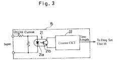
- Fig. 3 illustrates an example of the time detecting unit 15.
- This time detecting unit 15 includes an element such as, for example, a photo coupler 21 adapted to be activated when the driving current applied to the vibrating unit 2 exceeds the reference current value, and a counter circuit 22 for detecting the time length in dependence on the activation of the photo coupler 21.
- the photo coupler 21 is made up of a light emitting diode 21a and a light receiving transistor 21b and operable to continue generating an ON signal to the light receiving transistor 21b when the driving current exceeding the reference current value that is set to, for example, 0.4A flows across the input side light emitting diode 21a.
- the counter circuit 22 is operable to activate a time counter for generating, for example, a reference pulse during a period in which the light receiving transistor 21b receives the ON signal from the light emitting diode 21a and for counting the number of pulses generated to thereby detect the time length.
- the time detecting unit 15 can have a simple and low cost structure and is yet capable of allowing a transport drive to be performed efficiently.
- the driving frequency during the actual run can be set by applying a setting command to the frequency controlling unit 14 from a frequency setting unit 16 shown in Fig. 1.
- the frequency setting unit 16 has a function of setting the driving frequency during the actual run based on the time lengths detected by the time detecting unit 15 with respect to change of the driving frequency during the trial run.
- the amplitude of the driving current are so large at a resonant frequency or a frequency about equal to the resonant frequency that the time length during which the driving current exceeds the reference current value exhibits a predetermined pattern of change and, accordingly, the driving frequency at which such predetermined pattern of change is exhibited is used during the actual run.
- Setting of this driving frequency may be done during the actual run. In other words, the driving frequency at which the time length detected by continuously varying the driving frequency at a suitable timing during the actual run and then detecting the time length that exceeded the reference current value has exhibited the predetermined pattern of change is set as a new driving frequency.
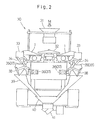
- Fig. 2 illustrates a schematic side view of a combination weighing apparatus 30 equipped with a number of electromagnetically driven vibrating feeder 1 each being of the structure discussed above as a transport devices 1.
- the articles M are successively supplied centrally onto a relatively low conical dispensing feeder 32 through a supply chute 31 positioned immediately thereabove.
- the dispensing feeder 32 is vibrated, the articles M falling onto the dispensing feeder 32 are radially outwardly dispensed into a plurality of the vibrating feeders (transport devices) 1 that are arranged radially outwardly with respect to and adjacent the conical dispensing feeder 32.
- the articles M so transferred to the vibrating feeders 1 are, after having been transported by the respective vibrating feeders 1, supplied into a corresponding number of pool hoppers 33 positioned radially outwardly of and adjacent the circular row of the vibrating feeders 1 and, after they have been temporarily pooled within the pool hoppers 33 in timed relation with a weighing operation, respective discharge gates 34 of the pool hoppers 33 are opened to allow the articles M to be supplied onto associated weighing hoppers 35 positioned immediately therebelow.
- the articles M which have been weighed are subsequently collected in a collecting chute 39 upon opening of discharge gates 38 of the respective weighing hoppers 35 and are then discharged from a discharge chute 40 by way of a timing gate 41 at a lower end of the discharge chute 40.
- the articles M so discharged are packaged by a bagging machine (not shown) to provide bagged products each containing a target weight of the articles M.
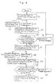
- the electromagnetically driven transport device (the vibrating feeder) 1 according to the first embodiment during the trial run will be described with reference to the waveforms shown in Figs. 4 and 5 and the flowchart shown in Fig. 6.
- the driving frequency of the driving power source for the vibrating unit 2 is automatically set to an actual driving frequency close to the natural frequency of the transport device 1.
- the driving frequency f of the inverter 13 which serves as the driving power source for the vibrating unit 2 is set to an initial value, for example, 70 Hz by the frequency controlling unit 14, and the vibrating unit 2 is driven for a predetermined length of time, for example, about 2 seconds with a feeder strength kept constant (Step S1 in Fig. 6).
- the time detecting unit 15 detects the length of time during which a driving current flowing through the electromagnet 8 of the vibrating unit 2 for each frequency (or pulse) of vibratory motion in directions opposite to each other exceeds the reference current value of 0.4A (Step S2).
- the transport device 1 is halted for a predetermined length of time, for example, about 8 sec. and a wait is then made until vibration is completely attenuated to fade out. It is to be noted that if the average value of the time length is about 0 ⁇ sec., the transport device 1 does barely undergo vibration and need not therefore be halted for a large length of time. In such case, the transport device 1 is halted for 2 seconds.
- the driving current applied during a single pass of vibratory motion of the transport device 1 represents such waveforms as shown by A and B in Fig. 4.
- a peak point of each of the waveforms A and B coincides with the point of maximum amplitude.
- the voltage applied to the vibrating unit 2 is fixed at a predetermined value and, under this condition, the greater the amplitude of vibration of the vibrating unit 2, the higher the driving current value.
- the closer the driving frequency f to the natural frequency of vibration the higher the driving current value and, therefore, the length of time during which the driving current exceeds the reference current value is large correspondingly.
- the driving frequency f is closer to the natural frequency of vibration of the transport device 1 when the driving current represents the waveform A than when the driving current represents the waveform B.
- the detection of the time length T may be carried out by the counter circuit 22. Specifically, a time counter included in the counter circuit 22 for generating reference pulses may be activated during the period in which the light receiving transistor 21b receives the ON signal from the light emitting diode 21a so that the number of pulses generated can be counted.
- the driving frequency is reduced from 70 Hz by, for example, 0.5 Hz and, hence, down to 69.5 Hz and the steps S1 and S2 are repeated to drive the vibrating unit 2 for detecting the time length T.
- the time length T is determined to be an average value of time lengths detected for a plurality of cycles of the current. Even thereafter, the driving frequency is reduced by 0.5 Hz and the step S1 and S2 are again repeated to drive the vibrating unit 2 for detecting the time length T. In this way, a cycle of the steps S1 and S2 is repeated a predetermined number of times at step S3 with the driving frequency is progressively reduced by an decrement of 0.5 Hz.
- the frequency setting unit 16 determines at step S5 whether the average value of the time lengths T detected in the manner described above decreases below the previous value three times consecutively before the driving frequency attains 30 Hz. If it is determined that the average value has fallen the previous value three times consecutively, it is deemed that the resonance frequency (that is, the actual driving frequency) may be found at a value about equal to the driving frequency for which the average value has started decreasing below the previous value and the program flow then goes to step S7. On the other hand, if the driving frequency attains 30 Hz before the average value falls the previous value three times consecutively, the feeder strength is increased a little at step S6, with the program flow subsequently returning to step S1.
- the driving frequency f is set to a value higher by 2 Hz than the driving frequency for which the average value has started decreasing and the vibrating unit 2 is then driven at that driving frequency f in a manner similar to that during step S1.
- the time length T is detected in a manner similar to that at step S2.
- the driving frequency is reduced down to a value lower by, for example, 0.1 Hz than that at step S7, and the vibrating unit 2 is driven in a manner similar to that at steps S7 and S8 so that the time length T can be detected.
- the foregoing procedures are repeated at step S3.
- the frequency setting unit 16 again determines at step S11 whether the average value of the time lengths T decreases below the previous value three times consecutively before the driving frequency attains 30 Hz. If it is determined that the average value has fallen the previous value three times consecutively, a frequency immediately before which the average value has started decreasing is utilized as the resonance frequency (that is, the actual driving frequency) at step S13. On the other hand, if the driving frequency attains 30 Hz before the average value falls the previous value three times consecutively, the feeder strength is increased a little at step S12, with the program flow subsequently returning to step S1. In this way, the frequency setting unit 16 sets the actual driving frequency based on change of the time length T and, therefore, even though the time length represents various values, it is possible to set the actual driving frequency appropriate to the change of the time lengths.
- the number of times during which the average value decreases may not be limited to three such as described, but may be one or two. It is also to be noted that in place of the average value of the time values T or in combination with the average value of the time lengths T, the foregoing determination may be made based on individual deviations of the time lengths T.
- the frequency setting unit 16 applies to the frequency controlling unit 14 a command instructing that the driving frequency determined at that time should be employed as an actual driving frequency during the actual run of the apparatus. Accordingly, during the actual run, the actual driving frequency of the inverter 13 is rendered to be the driving frequency equal to or about equal to the natural frequency of the transport device 1. The driving frequency of the driving power source of the vibrating unit 2 is thus automatically set to the actual driving frequency about equal to the natural frequency of the transport device 1.
- neither a detecting circuit for detecting an electric current or an electric voltage, a calculating unit nor a large capacity storage unit is needed and, accordingly, a highly efficient transport drive can be achieved with a simplified and low const system structure.
- the transport device that is, the electromagnetically driven vibrating feeder 1
- the driving frequency f at which the respective transport device is driven during the actual run is set by the frequency setting unit 16 in the manner described above with reference to the flowchart. Since the natural frequency generally varies from one transport device to another and, therefore, the driving frequency f is uniquely set to each transport device so that all of the vibrating feeders 1 can perform an efficient task of transporting the articles M onto the associated pool hoppers 33.
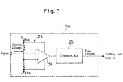
- the time detecting unit 15 has been shown and described as including the element 21 such as the photo coupler that is activated when the driving current exceeds the reference current value, so as to enable the time length T to be detected in dependence on the operation of this element 21, a time detecting unit 15A may be employed of a structure including, as shown in Fig. 7, a voltage comparator 23 for comparing a voltage corresponding to the previously described driving current with a voltage corresponding to the previously described reference current value to enable the time length T to be detected in dependence on an output condition of the voltage comparator 23.
- the voltage comparator 23 includes an operational amplifier (OP-amp) 24 operable to compare a driving voltage, corresponding to the driving current of the vibrating unit 2 that has been converted into a voltage, with a reference voltage (V CC , V DD ) of, for example, 715 V to provide the ON or OFF signal.
- the counter circuit 25 is operable to activate a time counter for generating, for example, a reference pulse during a period in which the operational amplifier 24 generates the ON signal, to count the number of pulses generated to thereby detect the time length.
- the time detecting unit 15A can have a simple and low cost structure and is yet capable of allowing a transport drive to be performed efficiently.
- FIG. 8 a second preferred embodiment of the present invention will be described.
- This second embodiment differs from the previously described first embodiment in that the system shown in Fig. 8 includes a storage unit 51, a modifier unit 52 and a selector unit 53.
- the storage unit 51 is a means for storing a reference current value of the driving current of the vibrating unit 2 and a reference time length during which the driving current of the vibrating unit 2 exceeds the reference current value.
- This storage unit 51 includes a first memory 51a for storing a plurality of different reference current values ia, ib, ⁇ and a second memory 51b for storing a plurality of different reference time lengths Ta, Tb, ⁇ . It is to be noted that the first memory 51a and the second memory 51b may be provided in different storage units separately.
- the modifier unit 52 is utilized to allow an operator to change the reference current values ia, ib, ⁇ and/or the reference time lengths Ta, Tb, ⁇ .
- One of the reference current values ia, ib, ⁇ and one of the reference time lengths Ta, Tb, ⁇ that is selectively read out from the storage unit 51 by the selector unit 53 can be inputted to the time detecting unit 45 and the frequency setting unit 46.
- the frequency setting unit 46 has a function of setting as a driving frequency to be used during the actual run, the frequency at which the time length detected by the time detecting unit 45 with respect to change in driving frequency during the trial run has exceeded a predetermined reference time length. Since the amplitude of the driving current increase at the resonant frequency or the frequency close to the resonant frequency enough for the time length, during which the driving current exceeds the reference current value, to exceed the reference time length, the driving frequency prevailing at that time is utilized during the actual run. As is the case with the previously described first embodiment, setting of this driving frequency may be carried out during the actual run.
- the time detecting unit 45 includes an analog-to-digital (A/D) converter 41 for converting an analog signal of the driving current of the vibrating unit 2 into a digital signal of the driving current, and a central processing unit (CPU) 40.
- the central processing unit 40 includes a counting means 42 for activating a time counter for generating a reference pulse, during a period in which the digital driving current exceeds the reference current value (the threshold value) and for counting the generated pulses, and a calculating means 43 for calculating the time length in dependence on the counted number of the pulses.
- Other structural features than those described above are substantially similar to those shown and described in connection with the first embodiment.
- the driving frequency f of the inverter 13, which is a driving power source of the vibrating unit 2 shown in Fig. 8 is set to an initial value by the frequency controlling unit 14 and the vibrating unit 2 is driven at this initial driving frequency at step P1 shown in Fig. 10.
- the time detecting unit 45 detects at step P2 the time length T during which the driving current flowing through the electromagnet 8 of the vibrating unit 2 exceeds the reference current value.
- the detecting operation of the time detecting unit 45 at step P2 is to detect the time length T during which the driving current i exceeds the predetermined current value ia selected and read out by the selector unit 53 from the storage unit 51. Detection of this time length T is carried out by the counting means 45 by activating the time counter for generating the reference pulses to count the number of pulses generated during a period in which the digital driving current exceeds the reference current value, and then causing the calculating means 43 to calculate the time length T in dependence on the counted number of the pulses.
- the time length T detected by the time detecting unit 45 is compared with the predetermined reference time length Ta by the frequency setting unit 46. If at this time the detected time length T does not exceed the reference time length Ta as determined at step P3, the frequency controlling unit 14 changes stepwise the driving frequency f of the inverter 13 by a predetermined value ⁇ , for example, 0.1 Hz and the vibrating unit 2 is further driven at step P4. In a similar manner, until the detected time length T exceeds the reference time length Ta, the flow of steps P2 to P4 for stepwise changing the driving frequency f by the predetermined value ⁇ is repeated.
- the frequency setting unit 46 applies to the frequency controlling unit 14 a command instructing that the driving frequency determined at that time should be employed as an actual driving frequency during the actual run of the apparatus. Accordingly, during the actual run, the actual driving frequency of the inverter 13 is rendered to be the driving frequency, which has been set in the manner described above, that is, the frequency equal to or about equal to the natural frequency of the transport device 1A. Therefore, even in the second embodiment of the present invention, neither a detecting circuit for detecting an electric current or an electric voltage, a calculating unit nor a large capacity storage unit is needed and, accordingly, a highly efficient transport drive can be achieved with a simplified and low const system structure.
- the storage unit 51 stores therein a plurality of reference current values ia, ib, ⁇ and a plurality of reference time lengths Ta, Tb, ⁇ for each of kinds of the articles M and/or each of types of the troughs and, based on an externally generated command, for example, the command issued by the operator, the selector unit 53 reads out appropriate ones of the reference current values and the reference time length out of the stored reference current values and the stored reference time lengths, respectively, which are then inputted to the time detecting unit 45 and the frequency setting unit 46, respectively. In this way, even though the kind of the articles M changes and/or the type of the trough changes, an efficient transport can be performed. This is accommodated for each of the vibr
- the reference current values and the reference time lengths stored in the storage unit 51 can be varied by the modifier unit 52 and, accordingly, even when the kind of the articles M to be transported is changed to a different kind not initially expected, the system can easily accommodate such change to perform an efficient transport activity.
- the system of the present invention has a versatility in application.
Abstract
Description
- The present invention relates to an electromagnetically driven transport device for electromagnetically vibrating a transport unit to transport an article to be transported, and a weighing apparatus utilizing such transport device.
- The transport device of the kind referred to above is so designed and so configured that the transport unit such as, for example, a trough for the support thereon of articles to be transported is mounted on a support base through a bracket that can be vibrated forwards and rearwards by an electromagnet to thereby transport the articles successively. In such case, in order to achieve an efficient transport of the articles, the driving frequency of an electric power source for driving the electromagnet is chosen to be equal to the natural frequency of the transport device.
- Methods hitherto known to coordinate the driving frequency with the natural frequency of the transport device includes the use of an inverter for variably setting the driving frequency so that the driving frequency at which the electric power supplied can be maximized is used to actually drive the electromagnet to achieve the transport such as disclosed in, for example, the Japanese Patent No. 2,770,295 (JPA3-223014); and the use of an inverter for variably setting the driving frequency so that the driving frequency at which the current can be maximized can be determined automatically at which the transport device is driven to achieve the transport of the articles such as disclosed in, for example, the Japanese Laid-open Patent Publication No. 7-060188.
- It has, however, been found that with the transport device that is driven to effect the actual transport at the driving frequency at which the electric power supplied can be maximized, a detecting circuit for detecting a voltage and a current is needed for calculation of the electric power and the transport device is accordingly complicated in structure. On the other hand, with the transport device that is driven at the driving frequency that is automatically determined at which the electric current can be maximized requires the use of a calculating unit and a storage unit of a correspondingly large capacity for detecting the electric current at all times and then to calculate the maximum value of the electric current and the transport device is therefore complicated in structure and high in cost.
- The present invention has therefore been devised to substantially eliminate the above discussed problems and inconveniences and is intended to provide a simple and low-cost, electromagnetically driven transport device capable of achieving an efficient transport and, also, a weighing apparatus utilizing at least one such electromagnetically driven transport device.
- In order to accomplish the foregoing object, the present invention provides an electromagnetically driven transport device which includes a transport unit for transporting an article to be transported; an electromagnetically driven vibrating unit for vibrating the transport unit to transport the article; a control unit for controlling a driving frequency of a driving power source of the vibrating unit; a time detecting unit for detecting a time length during which when the driving frequency is changed the driving current of the vibrating unit at each of frequency exceeds a reference current value; and a frequency setting unit for setting an actual driving frequency based on the time length detected by the time detecting unit.
- According to the present invention, when the driving frequency of the driving power source of the vibrating unit is varied by the control unit, the time detecting unit detects the time length during which the driving current of the vibrating unit at each of the frequencies exceeds the reference current value and the frequency setting unit sets the actual driving frequency based on the time length so detected. Accordingly, with no need to use any detecting circuit for detecting a voltage or a current, any calculating unit and any storage unit of a large capacity, the transport unit can be vibrated at the driving frequency close to the natural frequency of the transport device and, therefore, it is possible to achieve an efficient transport drive with a simplified and low-cost structure.
- In a preferred embodiment of the present invention, the time detecting unit may include an element that is activated when the driving current exceeds the reference current value, and is operable to detect the time length depending on an operating condition of such element. Alternatively, the time detecting unit may include a voltage comparator for comparing a voltage corresponding to the driving current with a voltage corresponding to the reference current value for outputting an output signal, so that the time length can be detected in dependence on a condition of the output signal from the voltage comparator. With this configuration, the time detecting unit can have a simple and low-cost structure to achieve an efficient transport drive.
- In a preferred embodiment of the present invention, the electromagnetically driven transport device may further include a memory for storing a reference current value and a detecting means for detecting a current value of the driving current, and the time detecting unit is operable to detect the time length based on the detected current value and the reference current value.
- According to this configuration, since the reference current value appropriate to a particular kind of the article to be transported and/or a particular type of the transport unit can be read out from the storage unit and be then used, it is possible to achieve an efficient transport drive appropriate to various modes of operation of the transport device.
- In a preferred embodiment of the present invention, the frequency setting unit may set the actual driving frequency based on change of the time length. Accordingly, even though the time length represents various values, the actual driving frequency appropriate to such change of the time length can be set.
- In a still further preferred embodiment of the present invention, detection performed by the time detecting unit is carried out during a trial run of the transport device and drive of the transport device at the actual driving frequency so set is carried out during an actual run of the transport device. In such case, from the very beginning of the actual run, the transport of the articles can be efficiently performed with the transport device driven at the proper actual driving frequency.
- The present invention also provides a weighing apparatus which includes a plurality of electromagnetically driven transport devices each being of the structure as discussed above and a weighing unit for weighing an article transported by each of the electromagnetically driven transport device. In this weighing apparatus, the actual driving frequency for each of the electromagnetically driven transport devices is preferably individually set by the frequency setting unit.
- With this weighing apparatus, since for each of the transport devices employed therein the transport unit can be vibrated at the actual driving frequency about equal to the natural frequency of the transport device, it is possible to achieve an efficient transport drive.
- In any event, the present invention will become more clearly understood from the following description of preferred embodiments thereof, when taken in conjunction with the accompanying drawings. However, the embodiments and the drawings are given only for the purpose of illustration and explanation, and are not to be taken as limiting the scope of the present invention in any way whatsoever, which scope is to be determined by the appended claims. In the accompanying drawings, like reference numerals are used to denote like parts throughout the several views, and:
- Fig. 1 is a schematic side view showing an electromagnetically driven transport device according to a first preferred embodiment of the present invention shown together with a circuit block diagram therefore;
- Fig. 2 is a schematic side view showing a combination weighing apparatus equipped with the electromagnetically driven transport devices shown in Fig. 1;
- Fig. 3 is a circuit diagram showing a time detecting unit employed in the electromagnetically driven transport device;
- Fig. 4 illustrates a waveform of a driving current used to drive the electromagnetically driven transport device;
- Fig. 5 is a chart used to describe the operation of a time detecting unit used in the electromagnetically driven transport device;
- Fig. 6 is a flowchart showing the sequence of setting of a driving frequency of the electromagnetically driven transport device;
- Fig. 7 is a circuit diagram showing an alternative form of the time detecting unit employed in the electromagnetically driven transport device;
- Fig. 8 is a side view showing the electromagnetically driven transport device according to a second preferred embodiment of the present invention shown together with a circuit block diagram therefore;
- Fig. 9 is a circuit block diagram showing the time detecting unit used in the electromagnetically driven transport device shown in Fig. 8; and
- Fig. 10 is a flowchart showing the sequence of setting of the driving frequency of the electromagnetically driven transport device.
-
- Referring to Fig. 1, there is schematically shown an electromagnetically driven
transport device 1 according to a first preferred embodiment of the present invention. Thetransport device 1 shown therein includes a vibratingunit 2 and a trough (a transport unit) 4 mounted on the vibratingunit 2 through abracket 3. The vibratingunit 2 in turn includes abase 7 mounted on amachine framework 5 serving as a transport unit on which thetransport device 1 is installed through a plurality of vibration isolatingelastic elements 6, anelectromagnet 8 mounted on thebase 7, front andrear leaf springs 9 extending parallel to each other and each secured at one end to a front or rear arm of thebracket 3 by means of a bolt Bl and nut and at the opposite end to a front or rear portion of thebase 7 by means of a bolt and nut, respectively, and a movable iron core 10 fixedly carried by thebracket 3 at a location adjacent an upper end portion of therear leaf spring 9 so as to confront theelectromagnet 8. Theelectromagnet 8 is adapted to be electrically powered by aninverter 13 serving as a source of an electric driving power. - When the
electromagnet 8 is electrically powered by theinverter 13, thebracket 3 can be vibrated through theleaf springs 9 in a vibrating direction that is oriented horizontally and slightly upwardly as shown by the arrow V relative to the horizontally lying trough 4, so that articles M placed on the trough 4 can be fed in a transport direction shown by the arrow P. - The
inverter 13 is fed an electric drive power from a directcurrent power source 12 operable to convert a commercial alternating current from a commercialAC power outlet 11 into a direct current, and the frequency of the electric drive power is controlled by afrequency controlling unit 14. The magnitude of the driving current supplied from theinverter 13 to theelectromagnet 8 of the vibratingunit 2 is detected by atime detecting unit 15. In other words, thetime detecting unit 15 detects an equivalent of the magnitude of the driving current in terms of a time length during which the driving current supplied from theinverter 13 to theelectromagnet 8 during a trial run of the apparatus prior to the actual operation of such apparatus exceeds a predetermined reference current value. - Fig. 3 illustrates an example of the
time detecting unit 15. Thistime detecting unit 15 includes an element such as, for example, aphoto coupler 21 adapted to be activated when the driving current applied to the vibratingunit 2 exceeds the reference current value, and acounter circuit 22 for detecting the time length in dependence on the activation of thephoto coupler 21. Thephoto coupler 21 is made up of alight emitting diode 21a and alight receiving transistor 21b and operable to continue generating an ON signal to thelight receiving transistor 21b when the driving current exceeding the reference current value that is set to, for example, 0.4A flows across the input sidelight emitting diode 21a. Thecounter circuit 22 is operable to activate a time counter for generating, for example, a reference pulse during a period in which thelight receiving transistor 21b receives the ON signal from thelight emitting diode 21a and for counting the number of pulses generated to thereby detect the time length. In this way, thetime detecting unit 15 can have a simple and low cost structure and is yet capable of allowing a transport drive to be performed efficiently. - The driving frequency during the actual run can be set by applying a setting command to the
frequency controlling unit 14 from afrequency setting unit 16 shown in Fig. 1. Specifically, thefrequency setting unit 16 has a function of setting the driving frequency during the actual run based on the time lengths detected by thetime detecting unit 15 with respect to change of the driving frequency during the trial run. By way of example, when the driving frequency is changed, the amplitude of the driving current are so large at a resonant frequency or a frequency about equal to the resonant frequency that the time length during which the driving current exceeds the reference current value exhibits a predetermined pattern of change and, accordingly, the driving frequency at which such predetermined pattern of change is exhibited is used during the actual run. Setting of this driving frequency may be done during the actual run. In other words, the driving frequency at which the time length detected by continuously varying the driving frequency at a suitable timing during the actual run and then detecting the time length that exceeded the reference current value has exhibited the predetermined pattern of change is set as a new driving frequency. - Fig. 2 illustrates a schematic side view of a
combination weighing apparatus 30 equipped with a number of electromagnetically driven vibratingfeeder 1 each being of the structure discussed above as atransport devices 1. The articles M are successively supplied centrally onto a relatively lowconical dispensing feeder 32 through asupply chute 31 positioned immediately thereabove. As the dispensingfeeder 32 is vibrated, the articles M falling onto the dispensingfeeder 32 are radially outwardly dispensed into a plurality of the vibrating feeders (transport devices) 1 that are arranged radially outwardly with respect to and adjacent theconical dispensing feeder 32. The articles M so transferred to the vibratingfeeders 1 are, after having been transported by the respective vibratingfeeders 1, supplied into a corresponding number ofpool hoppers 33 positioned radially outwardly of and adjacent the circular row of the vibratingfeeders 1 and, after they have been temporarily pooled within thepool hoppers 33 in timed relation with a weighing operation,respective discharge gates 34 of thepool hoppers 33 are opened to allow the articles M to be supplied ontoassociated weighing hoppers 35 positioned immediately therebelow. Each of the weighinghoppers 35 in cooperation with an associatedweight detector 36 such as, for example, a load cell coupled therewith forms aweighing unit 37, and theweight detector 36 detects the weight of the articles M, accommodated within the associatedweighing hopper 35, and then to output a weight signal indicative of the detected weight of the article M. The articles M which have been weighed are subsequently collected in acollecting chute 39 upon opening ofdischarge gates 38 of therespective weighing hoppers 35 and are then discharged from adischarge chute 40 by way of atiming gate 41 at a lower end of thedischarge chute 40. The articles M so discharged are packaged by a bagging machine (not shown) to provide bagged products each containing a target weight of the articles M. - The operation of the electromagnetically driven transport device (the vibrating feeder) 1 according to the first embodiment during the trial run will be described with reference to the waveforms shown in Figs. 4 and 5 and the flowchart shown in Fig. 6. In the illustrated embodiment, the driving frequency of the driving power source for the vibrating
unit 2 is automatically set to an actual driving frequency close to the natural frequency of thetransport device 1. - At the outset, the driving frequency f of the
inverter 13 which serves as the driving power source for the vibratingunit 2 is set to an initial value, for example, 70 Hz by thefrequency controlling unit 14, and the vibratingunit 2 is driven for a predetermined length of time, for example, about 2 seconds with a feeder strength kept constant (Step S1 in Fig. 6). During the vibratingunit 2 being driven in this way, and after a transient response of, for example, 1.5 sec., thetime detecting unit 15 detects the length of time during which a driving current flowing through theelectromagnet 8 of the vibratingunit 2 for each frequency (or pulse) of vibratory motion in directions opposite to each other exceeds the reference current value of 0.4A (Step S2). Thereafter, thetransport device 1 is halted for a predetermined length of time, for example, about 8 sec. and a wait is then made until vibration is completely attenuated to fade out. It is to be noted that if the average value of the time length is about 0 µsec., thetransport device 1 does barely undergo vibration and need not therefore be halted for a large length of time. In such case, thetransport device 1 is halted for 2 seconds. - The driving current applied during a single pass of vibratory motion of the
transport device 1 represents such waveforms as shown by A and B in Fig. 4. A peak point of each of the waveforms A and B coincides with the point of maximum amplitude. In this example, the voltage applied to the vibratingunit 2 is fixed at a predetermined value and, under this condition, the greater the amplitude of vibration of the vibratingunit 2, the higher the driving current value. In other words, the closer the driving frequency f to the natural frequency of vibration, the higher the driving current value and, therefore, the length of time during which the driving current exceeds the reference current value is large correspondingly. - By way of example, in Fig. 4, the driving frequency f is closer to the natural frequency of vibration of the
transport device 1 when the driving current represents the waveform A than when the driving current represents the waveform B. In view of this, the time length detection performed by thetime detecting unit 15 at the step S2 is such as to detect the time length T during which as a result of the driving current i exceeding the predetermined reference current value, for example, ia = 0.4A thelight emitting diode 21a of thephoto coupler 21 issues the ON signal to thelight receiving transistor 21b. It can thus be regarded that the larger the time length T, the higher the driving current i. The detection of the time length T may be carried out by thecounter circuit 22. Specifically, a time counter included in thecounter circuit 22 for generating reference pulses may be activated during the period in which thelight receiving transistor 21b receives the ON signal from thelight emitting diode 21a so that the number of pulses generated can be counted. - Then, the driving frequency is reduced from 70 Hz by, for example, 0.5 Hz and, hence, down to 69.5 Hz and the steps S1 and S2 are repeated to drive the vibrating
unit 2 for detecting the time length T. The time length T is determined to be an average value of time lengths detected for a plurality of cycles of the current. Even thereafter, the driving frequency is reduced by 0.5 Hz and the step S1 and S2 are again repeated to drive the vibratingunit 2 for detecting the time length T. In this way, a cycle of the steps S1 and S2 is repeated a predetermined number of times at step S3 with the driving frequency is progressively reduced by an decrement of 0.5 Hz. At each of driving frequencies the time lengths T so detected, during which the driving current has exceeded the reference current value ia (= 0.4A) are stored in a memory (not shown). - The
frequency setting unit 16 then determines at step S5 whether the average value of the time lengths T detected in the manner described above decreases below the previous value three times consecutively before the driving frequency attains 30 Hz. If it is determined that the average value has fallen the previous value three times consecutively, it is deemed that the resonance frequency (that is, the actual driving frequency) may be found at a value about equal to the driving frequency for which the average value has started decreasing below the previous value and the program flow then goes to step S7. On the other hand, if the driving frequency attains 30 Hz before the average value falls the previous value three times consecutively, the feeder strength is increased a little at step S6, with the program flow subsequently returning to step S1. - At step S7, the driving frequency f is set to a value higher by 2 Hz than the driving frequency for which the average value has started decreasing and the vibrating
unit 2 is then driven at that driving frequency f in a manner similar to that during step S1. Then at step S8, the time length T is detected in a manner similar to that at step S2. Again, the driving frequency is reduced down to a value lower by, for example, 0.1 Hz than that at step S7, and the vibratingunit 2 is driven in a manner similar to that at steps S7 and S8 so that the time length T can be detected. The foregoing procedures are repeated at step S3. The time lengths T during which the driving current exceeds the reference current value ia (= 0.4 A) at each of those driving frequency are stored in a memory at step S10. - The
frequency setting unit 16 again determines at step S11 whether the average value of the time lengths T decreases below the previous value three times consecutively before the driving frequency attains 30 Hz. If it is determined that the average value has fallen the previous value three times consecutively, a frequency immediately before which the average value has started decreasing is utilized as the resonance frequency (that is, the actual driving frequency) at step S13. On the other hand, if the driving frequency attains 30 Hz before the average value falls the previous value three times consecutively, the feeder strength is increased a little at step S12, with the program flow subsequently returning to step S1. In this way, thefrequency setting unit 16 sets the actual driving frequency based on change of the time length T and, therefore, even though the time length represents various values, it is possible to set the actual driving frequency appropriate to the change of the time lengths. - It is to be noted that in the foregoing description determination has been made of whether the average value of the time lengths T has decreased below the previous value three times consecutively, the number of times during which the average value decreases may not be limited to three such as described, but may be one or two. It is also to be noted that in place of the average value of the time values T or in combination with the average value of the time lengths T, the foregoing determination may be made based on individual deviations of the time lengths T.
- The
frequency setting unit 16 applies to the frequency controlling unit 14 a command instructing that the driving frequency determined at that time should be employed as an actual driving frequency during the actual run of the apparatus. Accordingly, during the actual run, the actual driving frequency of theinverter 13 is rendered to be the driving frequency equal to or about equal to the natural frequency of thetransport device 1. The driving frequency of the driving power source of the vibratingunit 2 is thus automatically set to the actual driving frequency about equal to the natural frequency of thetransport device 1. As discussed above, in the present invention, neither a detecting circuit for detecting an electric current or an electric voltage, a calculating unit nor a large capacity storage unit is needed and, accordingly, a highly efficient transport drive can be achieved with a simplified and low const system structure. - In the
combination weighing apparatus 30 shown in Fig. 2, the transport device, that is, the electromagnetically driven vibratingfeeder 1, is employed in a plural number, generally one for each of thepool hoppers 33. Accordingly, for each transport device or vibratingfeeder 1, the driving frequency f at which the respective transport device is driven during the actual run is set by thefrequency setting unit 16 in the manner described above with reference to the flowchart. Since the natural frequency generally varies from one transport device to another and, therefore, the driving frequency f is uniquely set to each transport device so that all of the vibratingfeeders 1 can perform an efficient task of transporting the articles M onto the associatedpool hoppers 33. - It is to be noted that although in the foregoing embodiment, the
time detecting unit 15 has been shown and described as including theelement 21 such as the photo coupler that is activated when the driving current exceeds the reference current value, so as to enable the time length T to be detected in dependence on the operation of thiselement 21, atime detecting unit 15A may be employed of a structure including, as shown in Fig. 7, avoltage comparator 23 for comparing a voltage corresponding to the previously described driving current with a voltage corresponding to the previously described reference current value to enable the time length T to be detected in dependence on an output condition of thevoltage comparator 23. - Referring now to Fig. 7, the
voltage comparator 23 includes an operational amplifier (OP-amp) 24 operable to compare a driving voltage, corresponding to the driving current of the vibratingunit 2 that has been converted into a voltage, with a reference voltage (VCC, VDD) of, for example, 715 V to provide the ON or OFF signal. Thecounter circuit 25 is operable to activate a time counter for generating, for example, a reference pulse during a period in which theoperational amplifier 24 generates the ON signal, to count the number of pulses generated to thereby detect the time length. In this way, thetime detecting unit 15A can have a simple and low cost structure and is yet capable of allowing a transport drive to be performed efficiently. - With reference to Figs. 8 to 10, a second preferred embodiment of the present invention will be described. This second embodiment differs from the previously described first embodiment in that the system shown in Fig. 8 includes a
storage unit 51, amodifier unit 52 and aselector unit 53. - The
storage unit 51 is a means for storing a reference current value of the driving current of the vibratingunit 2 and a reference time length during which the driving current of the vibratingunit 2 exceeds the reference current value. Thisstorage unit 51 includes afirst memory 51a for storing a plurality of different reference current values ia, ib, ··· and asecond memory 51b for storing a plurality of different reference time lengths Ta, Tb, ···. It is to be noted that thefirst memory 51a and thesecond memory 51b may be provided in different storage units separately. Themodifier unit 52 is utilized to allow an operator to change the reference current values ia, ib, ··· and/or the reference time lengths Ta, Tb, ···. One of the reference current values ia, ib, ··· and one of the reference time lengths Ta, Tb, ··· that is selectively read out from thestorage unit 51 by theselector unit 53 can be inputted to thetime detecting unit 45 and thefrequency setting unit 46. - The
frequency setting unit 46 has a function of setting as a driving frequency to be used during the actual run, the frequency at which the time length detected by thetime detecting unit 45 with respect to change in driving frequency during the trial run has exceeded a predetermined reference time length. Since the amplitude of the driving current increase at the resonant frequency or the frequency close to the resonant frequency enough for the time length, during which the driving current exceeds the reference current value, to exceed the reference time length, the driving frequency prevailing at that time is utilized during the actual run. As is the case with the previously described first embodiment, setting of this driving frequency may be carried out during the actual run. - As shown in Fig. 9, the
time detecting unit 45 includes an analog-to-digital (A/D)converter 41 for converting an analog signal of the driving current of the vibratingunit 2 into a digital signal of the driving current, and a central processing unit (CPU) 40. Thecentral processing unit 40 includes a counting means 42 for activating a time counter for generating a reference pulse, during a period in which the digital driving current exceeds the reference current value (the threshold value) and for counting the generated pulses, and a calculating means 43 for calculating the time length in dependence on the counted number of the pulses. Other structural features than those described above are substantially similar to those shown and described in connection with the first embodiment. - The operation of the electromagnetically driven
transport device 1A according to the second embodiment during the trial run will be described with reference to the flowchart shown in Fig. 10. At the outset, the driving frequency f of theinverter 13, which is a driving power source of the vibratingunit 2 shown in Fig. 8 is set to an initial value by thefrequency controlling unit 14 and the vibratingunit 2 is driven at this initial driving frequency at step P1 shown in Fig. 10. While the vibratingunit 2 is so driven, thetime detecting unit 45 detects at step P2 the time length T during which the driving current flowing through theelectromagnet 8 of the vibratingunit 2 exceeds the reference current value. - The detecting operation of the
time detecting unit 45 at step P2 is to detect the time length T during which the driving current i exceeds the predetermined current value ia selected and read out by theselector unit 53 from thestorage unit 51. Detection of this time length T is carried out by the counting means 45 by activating the time counter for generating the reference pulses to count the number of pulses generated during a period in which the digital driving current exceeds the reference current value, and then causing the calculating means 43 to calculate the time length T in dependence on the counted number of the pulses. - The time length T detected by the
time detecting unit 45 is compared with the predetermined reference time length Ta by thefrequency setting unit 46. If at this time the detected time length T does not exceed the reference time length Ta as determined at step P3, thefrequency controlling unit 14 changes stepwise the driving frequency f of theinverter 13 by a predetermined value α, for example, 0.1 Hz and the vibratingunit 2 is further driven at step P4. In a similar manner, until the detected time length T exceeds the reference time length Ta, the flow of steps P2 to P4 for stepwise changing the driving frequency f by the predetermined value α is repeated. - On the other hand, if the detected time length T exceeds the reference time length Ta as determined at step P3, the
frequency setting unit 46 applies to the frequency controlling unit 14 a command instructing that the driving frequency determined at that time should be employed as an actual driving frequency during the actual run of the apparatus. Accordingly, during the actual run, the actual driving frequency of theinverter 13 is rendered to be the driving frequency, which has been set in the manner described above, that is, the frequency equal to or about equal to the natural frequency of thetransport device 1A. Therefore, even in the second embodiment of the present invention, neither a detecting circuit for detecting an electric current or an electric voltage, a calculating unit nor a large capacity storage unit is needed and, accordingly, a highly efficient transport drive can be achieved with a simplified and low const system structure. - In the event that in the
transport device 1A the kind of the particles M to be transported thereby changes and/or the trough 4 is replaced with a different type of trough, the natural frequency of thetransport device 1A changes correspondingly. In order that thetransport device 1A of the present invention can accommodate those changes, thestorage unit 51 stores therein a plurality of reference current values ia, ib, ··· and a plurality of reference time lengths Ta, Tb, ··· for each of kinds of the articles M and/or each of types of the troughs and, based on an externally generated command, for example, the command issued by the operator, theselector unit 53 reads out appropriate ones of the reference current values and the reference time length out of the stored reference current values and the stored reference time lengths, respectively, which are then inputted to thetime detecting unit 45 and thefrequency setting unit 46, respectively. In this way, even though the kind of the articles M changes and/or the type of the trough changes, an efficient transport can be performed. This is accommodated for each of the vibratingfeeders 1A employed in the previously describedcombination weighing apparatus 30. - It is to be noted that the reference current values and the reference time lengths stored in the
storage unit 51 can be varied by themodifier unit 52 and, accordingly, even when the kind of the articles M to be transported is changed to a different kind not initially expected, the system can easily accommodate such change to perform an efficient transport activity. Thus, the system of the present invention has a versatility in application.
Claims (8)
- An electromagnetically driven transport device which comprises:a transport unit for transporting an article to be transported;an electromagnetically driven vibrating unit for vibrating the transport unit to transport the article;a control unit for controlling a driving frequency of a driving power source of the vibrating unit;a time detecting unit for detecting a time length during which when the driving frequency is changed the driving current of the vibrating unit at each of frequency exceeds a reference current value; anda frequency setting unit for setting an actual driving frequency based on the time length detected by the time detecting unit.
- The electromagnetically driven transport device as claimed in Claim 1, wherein the time detecting unit includes an element that is activated when the driving current exceeds the reference current value, and is operable to detect the time length depending on an operating condition of such element.
- The electromagnetically driven transport device as claimed in Claim 1 or Claim 2, wherein the time detecting unit includes a voltage comparator for comparing a voltage corresponding to the driving current with a voltage corresponding to the reference current value for outputting an output signal, and is operable to detect the time length in dependence on a condition of the output signal from the voltage comparator.
- The electromagnetically driven transport device as claimed in any of the preceding Claims, wherein the frequency setting unit is operable to set the actual driving frequency based on change of the time length.
- The electromagnetically driven transport device as claimed in any of the preceding Claims, further comprising a first memory for storing a reference current value and a detecting means for detecting a current value of the driving current, and the time detecting unit is operable to detect the time length based on the detected current value and the reference current value.
- The electromagnetically driven transport device as claimed in Claim 5, further comprising a second memory for storing a reference time length during which the driving current of the vibrating unit exceeds the reference current value and wherein the frequency setting unit is operable to set, as the actual driving frequency, the driving frequency for which the time length for each of frequencies detected exceeds the reference time length.
- The electromagnetically driven transport device as claimed in any of the preceding Claims, wherein detection performed by the time detecting unit is carried out during a trial run of the transport device and drive of the transport device at the actual driving frequency so set is carried out during an actual run of the transport device.
- A weighing apparatus which comprises:wherein an actual driving frequency for each of the electromagnetically driven transport devices is individually set by the frequency setting unit.a plurality of electromagnetically driven transport devices each being of the structure as defined in any of the preceding Claims; anda weighing unit for weighing an article transported by each of the electromagnetically driven transport device;
Applications Claiming Priority (2)
| Application Number | Priority Date | Filing Date | Title |
|---|---|---|---|
| JP2001263629 | 2001-08-31 | ||
| JP2001263629A JP4799780B2 (en) | 2000-08-31 | 2001-08-31 | Electromagnetic vibration type conveying device and weighing device equipped with the same |
Publications (2)
| Publication Number | Publication Date |
|---|---|
| EP1293452A1 true EP1293452A1 (en) | 2003-03-19 |
| EP1293452B1 EP1293452B1 (en) | 2006-06-21 |
Family
ID=19090354
Family Applications (1)
| Application Number | Title | Priority Date | Filing Date |
|---|---|---|---|
| EP02250658A Expired - Lifetime EP1293452B1 (en) | 2001-08-31 | 2002-01-31 | Electromagnetically driven transport device |
Country Status (3)
| Country | Link |
|---|---|
| US (1) | US6763934B2 (en) |
| EP (1) | EP1293452B1 (en) |
| DE (1) | DE60212533T2 (en) |
Families Citing this family (2)
| Publication number | Priority date | Publication date | Assignee | Title |
|---|---|---|---|---|
| US7228237B2 (en) | 2002-02-07 | 2007-06-05 | Applera Corporation | Automatic threshold setting and baseline determination for real-time PCR |
| EP1367010A1 (en) * | 2002-05-28 | 2003-12-03 | Ykk Corporation | Parts feeder and control method thereof |
Citations (5)
| Publication number | Priority date | Publication date | Assignee | Title |
|---|---|---|---|---|
| US3864618A (en) * | 1972-11-13 | 1975-02-04 | Mem Controls Inc | Electro-mechanical vibratory drive control |
| EP0432881A1 (en) * | 1989-12-05 | 1991-06-19 | Kabushiki Kaisha Toshiba | Vibratory feeding apparatus |
| EP0629568A2 (en) * | 1993-06-16 | 1994-12-21 | Ykk Corporation | Method and apparatus for controlling the drive of self-excited vibrating parts feeder |
| JPH0760188A (en) | 1993-06-16 | 1995-03-07 | Ykk Kk | Method and apparatus for controlling resonance frequency of self-excited vibration type parts feeder |
| EP0781718A2 (en) * | 1995-12-29 | 1997-07-02 | ISHIDA CO., Ltd. | Control method and controller of vibrating feeder |
Family Cites Families (17)
| Publication number | Priority date | Publication date | Assignee | Title |
|---|---|---|---|---|
| GB9008687D0 (en) * | 1990-04-18 | 1990-06-13 | Wright Machinery Co | Drive and monitoring system for a vibratory conveyor |
| US5726884A (en) | 1992-03-02 | 1998-03-10 | Alternative Systems, Inc. | Integrated hazardous substance tracking and compliance |
| US5664112A (en) | 1992-03-02 | 1997-09-02 | Alternative Systems, Inc. | Integrated hazardous substances management unit |
| US5291398A (en) | 1992-07-10 | 1994-03-01 | Hagan Bernard P | Method and system for processing federally insured annuity and life insurance investments |
| US5631828A (en) | 1992-07-10 | 1997-05-20 | Hagan; Bernard P. | Method and system for processing federally insured annuity and life insurance investments |
| US5532928A (en) | 1992-11-25 | 1996-07-02 | Recra Environmental, Inc. | Computer system and method for waste accounting, reduction, and evaluation |
| US5864685A (en) | 1994-02-28 | 1999-01-26 | Hagan; Bernard P. | Increasing income trust computer transaction system and insured investment account system |
| US5808916A (en) | 1994-08-04 | 1998-09-15 | City Of Scottsdale | Method for monitoring the environment |
| US6091835A (en) | 1994-08-31 | 2000-07-18 | Penop Limited | Method and system for transcribing electronic affirmations |
| US5793636A (en) | 1995-04-28 | 1998-08-11 | Westinghouse Electric Corporation | Integrated fuel management system |
| US5765140A (en) | 1995-11-17 | 1998-06-09 | Mci Corporation | Dynamic project management system |
| US5890129A (en) | 1997-05-30 | 1999-03-30 | Spurgeon; Loren J. | System for exchanging health care insurance information |
| US6085976A (en) | 1998-05-22 | 2000-07-11 | Sehr; Richard P. | Travel system and methods utilizing multi-application passenger cards |
| US6260044B1 (en) | 1998-02-04 | 2001-07-10 | Nugenesis Technologies Corporation | Information storage and retrieval system for storing and retrieving the visual form of information from an application in a database |
| US6122635A (en) | 1998-02-13 | 2000-09-19 | Newriver Investor Communications, Inc. | Mapping compliance information into useable format |
| US6067549A (en) | 1998-12-11 | 2000-05-23 | American Management Systems, Inc. | System for managing regulated entities |
| US6088700A (en) | 1999-08-06 | 2000-07-11 | Larsen; Kenneth N. | Automated forms completion for global information network applications |
-
2002
- 2002-01-29 US US10/057,885 patent/US6763934B2/en not_active Expired - Fee Related
- 2002-01-31 EP EP02250658A patent/EP1293452B1/en not_active Expired - Lifetime
- 2002-01-31 DE DE60212533T patent/DE60212533T2/en not_active Expired - Lifetime
Patent Citations (6)
| Publication number | Priority date | Publication date | Assignee | Title |
|---|---|---|---|---|
| US3864618A (en) * | 1972-11-13 | 1975-02-04 | Mem Controls Inc | Electro-mechanical vibratory drive control |
| EP0432881A1 (en) * | 1989-12-05 | 1991-06-19 | Kabushiki Kaisha Toshiba | Vibratory feeding apparatus |
| JPH03223014A (en) * | 1989-12-05 | 1991-10-02 | Toshiba Corp | Vibratory carrier device |
| EP0629568A2 (en) * | 1993-06-16 | 1994-12-21 | Ykk Corporation | Method and apparatus for controlling the drive of self-excited vibrating parts feeder |
| JPH0760188A (en) | 1993-06-16 | 1995-03-07 | Ykk Kk | Method and apparatus for controlling resonance frequency of self-excited vibration type parts feeder |
| EP0781718A2 (en) * | 1995-12-29 | 1997-07-02 | ISHIDA CO., Ltd. | Control method and controller of vibrating feeder |
Non-Patent Citations (2)
| Title |
|---|
| PATENT ABSTRACTS OF JAPAN vol. 015, no. 505 (M - 1194) 20 December 1991 (1991-12-20) * |
| PATENT ABSTRACTS OF JAPAN vol. 1995, no. 06 31 July 1995 (1995-07-31) * |
Also Published As
| Publication number | Publication date |
|---|---|
| US20020066645A1 (en) | 2002-06-06 |
| DE60212533D1 (en) | 2006-08-03 |
| EP1293452B1 (en) | 2006-06-21 |
| DE60212533T2 (en) | 2007-06-21 |
| US6763934B2 (en) | 2004-07-20 |
Similar Documents
| Publication | Publication Date | Title |
|---|---|---|
| US4350243A (en) | Control circuitry and method for vibratory feeder | |
| US5639995A (en) | Apparatus and method for controlling a vibratory feeder in a weighing machine | |
| EP0725263B1 (en) | Combinational weighing apparatus | |
| US4354618A (en) | Braking method and apparatus for vibratory feeder | |
| US20230049805A1 (en) | Vibration conveyor and method for regulating a vibration drive of a vibration conveyor | |
| AU2008251016A1 (en) | Discharging material from hoppers and the like | |
| EP1531134B1 (en) | Vibrating transport apparatus and method of detecting vibration characteristic | |
| EP1293452B1 (en) | Electromagnetically driven transport device | |
| EP0781718B1 (en) | Control method and controller of vibrating feeder | |
| US6291781B1 (en) | Combination weighing and counting apparatus | |
| RU2296085C2 (en) | Installation for automatic putting of food products, such as sausages, in trays | |
| US6012270A (en) | Apparatus for automatically bagging objects | |
| JP4799780B2 (en) | Electromagnetic vibration type conveying device and weighing device equipped with the same | |
| WO2007147419A1 (en) | Multihead weigher and method of operating such multihead weigher | |
| JP2000097752A (en) | Weighing device and vibration type conveyor | |
| JP3917700B2 (en) | Vibration feeder control method, control device, and weighing device | |
| JPH06144543A (en) | Conveying device | |
| JPH09263317A (en) | Control method and device for vibration feeder and measuring device | |
| JP6537347B2 (en) | Combination balance | |
| JP4081191B2 (en) | Linear conveyance device and combination weighing and counting device using the same | |
| JP3881608B2 (en) | Electromagnetic feeder and weighing device equipped with the same | |
| JP2004115265A (en) | Electromagnetic feeder and metering device provided with it | |
| JPH06198252A (en) | Multistep weight classifying apparatus | |
| JPH0528767B2 (en) | ||
| CA1154515A (en) | Braking method and apparatus for vibratory feeder |
Legal Events
| Date | Code | Title | Description |
|---|---|---|---|
| PUAI | Public reference made under article 153(3) epc to a published international application that has entered the european phase |
Free format text: ORIGINAL CODE: 0009012 |
|
| AK | Designated contracting states |
Designated state(s): AT BE CH CY DE DK ES FI FR GB GR IE IT LI LU MC NL PT SE TR Kind code of ref document: A1 Designated state(s): AT BE CH CY DE DK ES FI FR GB GR IE IT LI LU MC NL PT SE TR |
|
| AX | Request for extension of the european patent |
Extension state: AL LT LV MK RO SI |
|
| 17P | Request for examination filed |
Effective date: 20030904 |
|
| AKX | Designation fees paid |
Designated state(s): DE GB GR IT |
|
| GRAP | Despatch of communication of intention to grant a patent |
Free format text: ORIGINAL CODE: EPIDOSNIGR1 |
|
| RBV | Designated contracting states (corrected) |
Designated state(s): DE FR GB IT |
|
| GRAS | Grant fee paid |
Free format text: ORIGINAL CODE: EPIDOSNIGR3 |
|
| GRAA | (expected) grant |
Free format text: ORIGINAL CODE: 0009210 |
|
| AK | Designated contracting states |
Kind code of ref document: B1 Designated state(s): DE FR GB IT |
|
| PG25 | Lapsed in a contracting state [announced via postgrant information from national office to epo] |
Ref country code: IT Free format text: LAPSE BECAUSE OF FAILURE TO SUBMIT A TRANSLATION OF THE DESCRIPTION OR TO PAY THE FEE WITHIN THE PRESCRIBED TIME-LIMIT;WARNING: LAPSES OF ITALIAN PATENTS WITH EFFECTIVE DATE BEFORE 2007 MAY HAVE OCCURRED AT ANY TIME BEFORE 2007. THE CORRECT EFFECTIVE DATE MAY BE DIFFERENT FROM THE ONE RECORDED. Effective date: 20060621 |
|
| REG | Reference to a national code |
Ref country code: GB Ref legal event code: FG4D |
|
| REF | Corresponds to: |
Ref document number: 60212533 Country of ref document: DE Date of ref document: 20060803 Kind code of ref document: P |
|
| ET | Fr: translation filed | ||
| PLBE | No opposition filed within time limit |
Free format text: ORIGINAL CODE: 0009261 |
|
| STAA | Information on the status of an ep patent application or granted ep patent |
Free format text: STATUS: NO OPPOSITION FILED WITHIN TIME LIMIT |
|
| 26N | No opposition filed |
Effective date: 20070322 |
|
| PGFP | Annual fee paid to national office [announced via postgrant information from national office to epo] |
Ref country code: IT Payment date: 20080129 Year of fee payment: 7 |
|
| PGFP | Annual fee paid to national office [announced via postgrant information from national office to epo] |
Ref country code: FR Payment date: 20080108 Year of fee payment: 7 |
|
| REG | Reference to a national code |
Ref country code: FR Ref legal event code: ST Effective date: 20091030 |
|
| PG25 | Lapsed in a contracting state [announced via postgrant information from national office to epo] |
Ref country code: FR Free format text: LAPSE BECAUSE OF NON-PAYMENT OF DUE FEES Effective date: 20090202 |
|
| PGFP | Annual fee paid to national office [announced via postgrant information from national office to epo] |
Ref country code: DE Payment date: 20100211 Year of fee payment: 9 Ref country code: GB Payment date: 20100202 Year of fee payment: 9 |
|
| PG25 | Lapsed in a contracting state [announced via postgrant information from national office to epo] |
Ref country code: IT Free format text: LAPSE BECAUSE OF NON-PAYMENT OF DUE FEES Effective date: 20090131 |
|
| GBPC | Gb: european patent ceased through non-payment of renewal fee |
Effective date: 20110131 |
|
| PG25 | Lapsed in a contracting state [announced via postgrant information from national office to epo] |
Ref country code: GB Free format text: LAPSE BECAUSE OF NON-PAYMENT OF DUE FEES Effective date: 20110131 |
|
| REG | Reference to a national code |
Ref country code: DE Ref legal event code: R119 Ref document number: 60212533 Country of ref document: DE Effective date: 20110802 |
|
| PG25 | Lapsed in a contracting state [announced via postgrant information from national office to epo] |
Ref country code: DE Free format text: LAPSE BECAUSE OF NON-PAYMENT OF DUE FEES Effective date: 20110802 |