EP1293351A2 - Sheet conveying method, sheet attracting conveying apparatus, and recording apparatus - Google Patents
Sheet conveying method, sheet attracting conveying apparatus, and recording apparatus Download PDFInfo
- Publication number
- EP1293351A2 EP1293351A2 EP02020764A EP02020764A EP1293351A2 EP 1293351 A2 EP1293351 A2 EP 1293351A2 EP 02020764 A EP02020764 A EP 02020764A EP 02020764 A EP02020764 A EP 02020764A EP 1293351 A2 EP1293351 A2 EP 1293351A2
- Authority
- EP
- European Patent Office
- Prior art keywords
- voltage
- sheet
- electrode
- electrodes
- conveyance belt
- Prior art date
- Legal status (The legal status is an assumption and is not a legal conclusion. Google has not performed a legal analysis and makes no representation as to the accuracy of the status listed.)
- Granted
Links
- 238000000034 method Methods 0.000 title claims abstract description 14
- 102000011842 Serrate-Jagged Proteins Human genes 0.000 claims description 2
- 108010036039 Serrate-Jagged Proteins Proteins 0.000 claims description 2
- 238000007599 discharging Methods 0.000 claims description 2
- 239000003595 mist Substances 0.000 description 10
- -1 polyethylene Polymers 0.000 description 8
- 239000002344 surface layer Substances 0.000 description 8
- 239000010410 layer Substances 0.000 description 5
- 229920001343 polytetrafluoroethylene Polymers 0.000 description 4
- 239000004810 polytetrafluoroethylene Substances 0.000 description 4
- 230000005611 electricity Effects 0.000 description 3
- 238000002474 experimental method Methods 0.000 description 3
- 229920003002 synthetic resin Polymers 0.000 description 3
- 239000000057 synthetic resin Substances 0.000 description 3
- 239000002033 PVDF binder Substances 0.000 description 2
- 239000004952 Polyamide Substances 0.000 description 2
- 239000004698 Polyethylene Substances 0.000 description 2
- 239000004642 Polyimide Substances 0.000 description 2
- 239000004743 Polypropylene Substances 0.000 description 2
- 238000009835 boiling Methods 0.000 description 2
- 238000004140 cleaning Methods 0.000 description 2
- 239000004020 conductor Substances 0.000 description 2
- 229920002647 polyamide Polymers 0.000 description 2
- 229920000515 polycarbonate Polymers 0.000 description 2
- 239000004417 polycarbonate Substances 0.000 description 2
- 229920000573 polyethylene Polymers 0.000 description 2
- 229920001721 polyimide Polymers 0.000 description 2
- 229920001155 polypropylene Polymers 0.000 description 2
- 238000000926 separation method Methods 0.000 description 2
- 229920002050 silicone resin Polymers 0.000 description 2
- OKTJSMMVPCPJKN-UHFFFAOYSA-N Carbon Chemical compound [C] OKTJSMMVPCPJKN-UHFFFAOYSA-N 0.000 description 1
- RYGMFSIKBFXOCR-UHFFFAOYSA-N Copper Chemical compound [Cu] RYGMFSIKBFXOCR-UHFFFAOYSA-N 0.000 description 1
- BQCADISMDOOEFD-UHFFFAOYSA-N Silver Chemical compound [Ag] BQCADISMDOOEFD-UHFFFAOYSA-N 0.000 description 1
- 229910052799 carbon Inorganic materials 0.000 description 1
- 230000000052 comparative effect Effects 0.000 description 1
- 239000003989 dielectric material Substances 0.000 description 1
- 230000000694 effects Effects 0.000 description 1
- 231100000989 no adverse effect Toxicity 0.000 description 1
- 229920005989 resin Polymers 0.000 description 1
- 239000011347 resin Substances 0.000 description 1
- 229910052709 silver Inorganic materials 0.000 description 1
- 239000004332 silver Substances 0.000 description 1
- 238000010186 staining Methods 0.000 description 1
- 238000011144 upstream manufacturing Methods 0.000 description 1
- XLYOFNOQVPJJNP-UHFFFAOYSA-N water Substances O XLYOFNOQVPJJNP-UHFFFAOYSA-N 0.000 description 1
Images




Classifications
-
- B—PERFORMING OPERATIONS; TRANSPORTING
- B65—CONVEYING; PACKING; STORING; HANDLING THIN OR FILAMENTARY MATERIAL
- B65H—HANDLING THIN OR FILAMENTARY MATERIAL, e.g. SHEETS, WEBS, CABLES
- B65H5/00—Feeding articles separated from piles; Feeding articles to machines
- B65H5/004—Feeding articles separated from piles; Feeding articles to machines using electrostatic force
-
- B—PERFORMING OPERATIONS; TRANSPORTING
- B41—PRINTING; LINING MACHINES; TYPEWRITERS; STAMPS
- B41J—TYPEWRITERS; SELECTIVE PRINTING MECHANISMS, i.e. MECHANISMS PRINTING OTHERWISE THAN FROM A FORME; CORRECTION OF TYPOGRAPHICAL ERRORS
- B41J11/00—Devices or arrangements of selective printing mechanisms, e.g. ink-jet printers or thermal printers, for supporting or handling copy material in sheet or web form
- B41J11/007—Conveyor belts or like feeding devices
-
- B—PERFORMING OPERATIONS; TRANSPORTING
- B65—CONVEYING; PACKING; STORING; HANDLING THIN OR FILAMENTARY MATERIAL
- B65H—HANDLING THIN OR FILAMENTARY MATERIAL, e.g. SHEETS, WEBS, CABLES
- B65H2404/00—Parts for transporting or guiding the handled material
- B65H2404/20—Belts
-
- B—PERFORMING OPERATIONS; TRANSPORTING
- B65—CONVEYING; PACKING; STORING; HANDLING THIN OR FILAMENTARY MATERIAL
- B65H—HANDLING THIN OR FILAMENTARY MATERIAL, e.g. SHEETS, WEBS, CABLES
- B65H2515/00—Physical entities not provided for in groups B65H2511/00 or B65H2513/00
- B65H2515/70—Electrical or magnetic properties, e.g. electric power or current
Definitions
- This invention relates to a recording apparatus, a sheet conveying method for the recording apparatus, and a sheet attracting conveying device for the recording apparatus.
- an inkjet recording apparatus using a full-line type recording head can record at high speed with high definition.
- a generally known method for attracting and conveying a conveying object is to dispose an electrically conductive electrode to the recording apparatus and create electrostatic force by applying electric charge to the electrode.
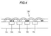
- FIG.4 is a cross-sectional view of a conveyance belt.
- the conveyance belt includes a first electrode 36a, a second electrode 36b, which are formed from electrically conductive resin respectively, a base layer 36c, and a surface layer.
- a voltage supplying means includes a voltage supplying brush 51 contacting with a voltage receiving portion for supplying electric charge thereto, a voltage supplying electrode 52, and a support member 53.
- the surface layer and the voltage receiving portion 36e form a flat plane. Electric charge is supplied constantly from the voltage supplying brush 51 to the first electrode 36a for creating electrostatic force. Therefore, a suitable and a constant attraction force can be generated.
- the comb-teeth electrode of the conventional conveying apparatus in general, being constantly applied with same voltage raises problems such as staining of an image due to ink mist attracted to the proximity of the electrode or blurring of an image due to ink droplets deviating from a targeted impact area.
- a representative structure of this invention is a sheet conveying method in use of a conveyance belt formed with a plurality of electrodes for attracting a sheet with electrostatic force, wherein the electrodes are applied with a voltage changed along with the lapse of time for generating attraction force, and wherein the integral value of voltage applied to one electrode has a polarity different from that of the integral value of voltage applied to another adjacent electrode.
- the sheet conveying method of this invention is characterized by using a conveyance belt formed with a plurality of electrodes for attracting a sheet with electrostatic force, wherein the electrodes are applied with a voltage changed along with the lapse of time for generating attraction force, and wherein the integral value of voltage applied to one electrode has a polarity different from that of the integral value of voltage applied to another adjacent electrode.
- FIG.1 is an explanatory view showing a voltage supplying means of this invention.
- the voltage supplying means includes a voltage supplying brush 51, a voltage supplying electrode 52, and a support member 53.
- the right side of FIG.1 is the sheet feeding side and the left side thereof is the sheet delivery side, wherein a recording paper P (sheet) is conveyed from the right side to the left side of FIG.1.
- the voltage supplying brush 51 contacts with a voltage receiving portion of a belt and supplies electric voltage to the voltage receiving portion of the belt.
- FIG.2 is an explanatory view showing the positional relation among a voltage supplying means, a conveyance belt serving as a sheet conveying means, and a recording head 7 serving as a recording means.
- a conveyed recording paper P is attracted to the belt.
- the recording paper P is attracted to the belt with a prescribed voltage.
- Each recording head is aligned with an interval of 2cm, and the width of the recording head in the conveying direction is 2 cm.
- the length of the voltage supplying electrode 52 which is 20 cm, is the necessary and sufficient length for supplying voltage from the beginning of the recording head 7Y arranged most upstream to a recording head 7K arranged most downstream.
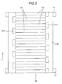
- FIG.3 is an explanatory view showing a conveyance belt 31 and an attraction force generating means 36.
- FIG.3 shows the belt when the apparatus body is seen directly from above.
- the attraction force generating means 36 includes the first electrodes 36a and the second electrodes 36b.
- the first electrode 36a and the second electrode 36b have strip-like shapes and are plurally aligned parallel to each other in the width direction of the conveyance belt 31.
- the first electrodes 36a and the second electrodes 36b face to each other in a direction perpendicularly intersecting with the conveying direction of the belt to form a comb-teeth shape.
- a voltage receiving portion 36el of the first electrode 36a (first voltage receiving portion) and a voltage receiving portion 36e2 of the second electrode 36a (second voltage receiving portion), having a length longer than the width of each electrode 36a, 36b, are arranged on both sides of the conveyance belt 31 with respect to a conveying direction, and thereby positioning the voltage receiving portion 36el on a right end side with respect to the conveying direction of the conveyance belt 31 and the voltage receiving portion 36e2 on a left side with respect to the conveying direction of the conveyance belt 31.
- the attraction force generating means 36 also includes a conductive voltage supplying brush 51 for contacting with each voltage receiving portion 36e with a prescribed pressure.
- the voltage supplying brush 51 is preferably made of a conductive material having a volume resistivity no more than 10 5 Ohms-cm.
- FIG.4 is a view for explaining the generation of attraction force by the attraction force generating means 36.
- an electric force is created in the arrow direction, thereby forming an electricity field line.
- attraction force is created at the upper side of the conveyance belt 31 allowing the recording paper P on the conveyance belt 31 to be attracted to the conveyance belt 31.
- the surface layer 36d in this invention has a higher volume resistivity than that of the base layer 36c, the electricity field line and the sheet attraction force can be generated greater at the upper side of the conveyance belt 31.
- FIG.5 is an explanatory view of a voltage supplying means supplying electricity to a conveyance belt.
- the attraction force generating means 36 comprises the first electrode 36a, the second electrode 36b, formed from conductive material respectively, the base layer 36c, the surface layer 36d, the voltage receiving portion 36e, the voltage supplying brush 51, the voltage supplying electrode 52, and the support member 53.
- the voltage receiving portion 36e is disposed to share a same plane with the surface layer 36d.
- the voltage supplying brush 51 contacts the voltage receiving portion 36e with a certain pressure and supplies voltage thereto.
- the base layer 36c and the surface layer 36d which are formed from dielectric material, have the first electrode 36a and the second electrode 36b protectively disposed therebetween.
- the base layer 36c has a volume resistivity from 10 12 Ohms-cm to 10 17 Ohms-cm
- the surface layer 36d has a volume resistivity from 10 9 Ohms-cm to 10 14 Ohms-cm, in which both are formed from a synthetic resin such as polyethylene, polypropylene, polyamide, polycarbonate, PTFE (polytetrafluoroethylene), PFE (polyfluoroethylene), PVDF (polyvinylidene fluoride), polyimide, or silicone resin.
- the voltage receiving portion 36e has a volume resistivity from 10 -1 Ohms-cm to 10 5 Ohms-cm and is formed from a conductive synthetic resin comprising carbon, or a conductive paste mixed with silver or copper powder.
- the water repellency for the surface layer 36d and the top surface of the voltage receiving portion 36e can be further improved by applying, for example, a fluororesin process thereto.
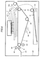
- FIG.6 is a cross-sectional view showing an overall structure of a recording apparatus of this invention.
- a pushing plate 21 for stacking recording paper P and a feeding rotary body 22 for feeding recording paper P are attached to a base 20, and the pushing plate 21 is rotatable around a rotation axis engaged to the base 20 and is pushed by a pushing plate spring 24 toward the feeding rotary body 22.
- the pushing plate 21 has a separation pad (not shown) with a high frictional coefficient for preventing double-feed of recording paper P and a separation nail-member (not shown) for separating the recording paper P .
- a release cam (not shown) is provided at the base 20 for disengaging the contact between the pushing plate 21 and the feeding rotary body 22.
- the release cam presses down the pushing plate 21, thereby disengaging the contact between the pushing plate 21 and the feeding rotary body 22.
- a drive force of the conveyance roller 32 while in this state, is transmitted to the feeding rotary body 22 and the release cam through gears or the like, the pushing plate 21 moves up to allow the feeding rotary body 22 contact with the recording paper P .
- the apparatus then starts sheet feeding upon picking up the recording paper P along with the rotation of the feeding rotary body 22.
- the feeding rotary body 22 continues to rotate until the recording paper P is delivered to the conveyance section.
- the conveyance section serving to attract the recording paper P includes a conveyance belt 31 for sheet conveyance and an unshown PE (paper end) sensor.
- the conveyance belt 31 is driven by a driving roller 34 and is tensely wound around the conveyance roller 32 and a pressure roller 35, which serve as a driven roller, respectively.
- the driving roller 34 is the driving source for a belt motor 50.
- the conveyance belt 31 is formed from a synthetic resin such as polyethylene. polypropylene. polyamide, polycarbonate, PTFE (polytetrafluoroethylene), PFE (polyfluoroethylene), PVDF (polyvinylidene fluoride), polyimide, or silicone resin and is shaped as an endless belt.
- the voltage supplying means is earlier described in detail with reference to other drawings.
- the voltage supplying means applies a DC bias voltage of approximately 100V ⁇ 3 kV superimposed on an AC voltage for allowing the recording paper P to be closely attracted to the conveyance belt 31.
- the peak value of the AC voltage is preferable to be no more than 3 times of the DC bias voltage, and more preferable to be no more than the DC bias voltage since an exceedingly high AC voltage swinging greatly toward the opposite potential weakens the attraction force.
- the peak value of the AC voltage is preferable to be no less than 1/3 times of the DC bias voltage, and more preferable to be no less than 1/2 times of the DC bias voltage since an exceedingly low AC voltage weakens the effect of equalizing the surface potential of the recording paper (The explanation for a high voltage generating means and a high voltage control means will be omitted). It is to be noted that the conveyance belt is moved at a speed of 170mm per second.
- the conveyance belt 31 and a pinch roller 33 driven by the conveyance roller 32 make contact in a position opposite from the conveyance roller 32.
- the recording head 7 (the recording head 7Y is for yellow, a recording head 7M is for magenta, a recording head 7C is for cyan, and the recording head 7K is for black) is disposed downstream in the conveying direction of the conveyance roller 32.
- the recording head 7, which is a line-type inkjet recording head having plural nozzles arrayed in a direction perpendicularly intersecting to the conveying direction, uses a line-type head having a row of nozzles whose length is the same as or greater than sheet width.
- the recording head 7, which is also a thermal type recording head applies heat to ink with a heater or the like.
- the ink is subject to film boiling by the heat, and pressure change created by growing and shrinking of vapor bubbles caused by the film boiling makes the nozzles discharge the ink, thereby forming an image on the recording paper P .
- the resolution in recording with the recording head is 600 dpi.
- the delivery section comprises a delivery roller 41 and a spur 42.
- the recording paper P having an image formed thereto is delivered to a delivery tray 43 by being conveyed in a manner nipped between the delivery roller 41 and the spur 42.
- the area in which the spur contacts the recording paper P is small, and therefore, the spur 42 serving as a rotating member has no adverse effect on an ink image even when ejection of ink causes the ink image to contact with a side of the recording paper P upon which the image recorded.
- Numeral 38 is a cleaning roller used for cleaning the belt 31.
- Numeral 39 is a de-electrifying brush used for earthing the charge remaining on the belt and for enabling easy sheet delivery.
- Numeral 50 is a belt motor serving as a driving source for rotating the conveyance belt.
- a bias voltage of ⁇ 750 V superimposed on a sinusoidal wave voltage having an amplitude of 1500 V is applied to the positive electrodes and negative electrodes, respectively.
- the frequency of the sinusoidal wave in this case was 2500Hz.
- Examples for solving the problem of images stained by ink mist attracted in the vicinity of an electrode is disclosed in Japanese Patent Laid-Open Publication No.Hei5-8392, in which an electrode is arranged contacting to a recording paper, and an electrode is arranged surrounding an ink discharging port for controlling the ink.
- the conveyance belt for the invention described in the publication is different from the belt with a comb-teeth electrode of the present invention, that is, the conveyance belt for the invention described in the publication is a type that attracts the recording paper by accumulating electrical charge on the surface of the belt.
- a waveform voltage which is changed along with the lapse of time, is employed in this invention as the voltage applied to each electrode for generating attraction force.
- an AC voltage biased with a DC bias voltage (various voltages which are combinations of a sinusoidal wave, a triangular wave, a serrate wave, a square wave, or a rectified wave of such waveforms, etc.) was supplied to the electrodes to serve as an attraction voltage allowing the positive electrode to constantly have positive electric potential and the negative electrode to constantly have negative electric potential.
- the surface potential of the recording paper with respect to the attracted portion of the recording paper not only swung toward positive potential but also swung toward negative potential even at a position above the positive electrode, and swung not only toward negative potential but also toward positive potential even at a position above the negative electrode. That is, an AC voltage or the like biased with a DC bias voltage allows to change the surface potential of the recording paper and create an indefinite surface potential of the recording paper, thereby, preventing adherence of ink mist and impact deviation of ink droplets.
- a new belt was attached to the apparatus of the first embodiment.
- bias voltages of ⁇ 500 V, ⁇ 1000 V, and ⁇ 1500 V superimposed on sinusoidal waves voltages with amplitudes of 500 V, 1000 V, and 1500V are applied to the positive and negative electrodes.
- a conveyance experiment was performed by changing the AC frequency to 50 Hz, 100 Hz, 250 Hz, 500 Hz, 1000 Hz, and 2000 Hz.
- FIG.7 shows a result of measuring the surface potential of the conveyance belt when a recording paper is attracted to the conveyance belt under the conditions where bias voltage of ⁇ 500 V is superimposed on a sinusoidal wave with an amplitude of 1000 V.
- FIG.7 is one example showing a result of measuring the surface potential of the belt in using the conveying method of this embodiment.
- the waveforms swing toward positive or negative at the portions of the electrodes where no recording paper is attached to the belt, and yet, the surface potential swing toward both positive and negative at the portions where the recording paper is attached to the belt. This restrains electrically charged mist from concentrating on a single portion of the recording paper. Therefore, concentration of mist and impact deviation of ink droplets can be prevented.
- the belt used in the second embodiment is attached to the apparatus in the first embodiment, in which recording and conveying were tested by applying DC voltages of ⁇ 500 V, ⁇ 1000 V, ⁇ 1500 V, and ⁇ 2000 V to the positive and negative electrodes.
- DC voltages ⁇ 500 V, ⁇ 1000 V, ⁇ 1500 V, and ⁇ 2000 V.
- adherence of ink mist corresponding to the arrangement of the electrodes could be visually recognized through the naked eye in part of the images. This becomes more significant as the voltage becomes higher.
- the voltage is ⁇ 1500 V or more, blurring of images from impact deviation of ink droplets could also be visually recognized through the naked eye.
- This invention is not to be restricted to the foregoing embodiments in which the voltage receiving portion 36el of the first electrode 36a is disposed on one end of the conveyance belt 31 while the voltage receiving portion 36e2 is disposed on the other opposite end of the conveyance belt 31.
- the voltage receiving portion 36el of the first electrode 36a and the voltage receiving portion 36e2 of the second electrode 36b can also be disposed on the same end of the conveyance belt 31.
- the present invention relates to a sheet conveying method in use of a conveyance belt formed with a plurality of electrodes for attracting a sheet with electrostatic force.
- the electrodes are applied with a voltage changed along with the lapse of time for generating attraction force, and the integral value of voltage applied to one electrode has a polarity different from that of the integral value of voltage applied to another adjacent electrode.
Landscapes
- Engineering & Computer Science (AREA)
- Mechanical Engineering (AREA)
- Feeding Of Articles By Means Other Than Belts Or Rollers (AREA)
- Ink Jet (AREA)
- Handling Of Cut Paper (AREA)
- Handling Of Sheets (AREA)
- Paper Feeding For Electrophotography (AREA)
Abstract
Description
- This invention relates to a recording apparatus, a sheet conveying method for the recording apparatus, and a sheet attracting conveying device for the recording apparatus.
- Among inkjet recording apparatuses, an inkjet recording apparatus using a full-line type recording head can record at high speed with high definition. A generally known method for attracting and conveying a conveying object is to dispose an electrically conductive electrode to the recording apparatus and create electrostatic force by applying electric charge to the electrode.
- A description of prior art is given hereinafter with reference to FIG.4 and FIG.5. FIG.4 is a cross-sectional view of a conveyance belt. The conveyance belt includes a
first electrode 36a, asecond electrode 36b, which are formed from electrically conductive resin respectively, abase layer 36c, and a surface layer. In FIG.5, a voltage supplying means includes avoltage supplying brush 51 contacting with a voltage receiving portion for supplying electric charge thereto, avoltage supplying electrode 52, and asupport member 53. The surface layer and thevoltage receiving portion 36e form a flat plane. Electric charge is supplied constantly from thevoltage supplying brush 51 to thefirst electrode 36a for creating electrostatic force. Therefore, a suitable and a constant attraction force can be generated. - However, the comb-teeth electrode of the conventional conveying apparatus, in general, being constantly applied with same voltage raises problems such as staining of an image due to ink mist attracted to the proximity of the electrode or blurring of an image due to ink droplets deviating from a targeted impact area.
- It is an object of this invention to prevent mist adhering upon a sheet and to prevent impact deviation of ink droplets.
- In means to achieve the foregoing object, a representative structure of this invention is a sheet conveying method in use of a conveyance belt formed with a plurality of electrodes for attracting a sheet with electrostatic force, wherein the electrodes are applied with a voltage changed along with the lapse of time for generating attraction force, and wherein the integral value of voltage applied to one electrode has a polarity different from that of the integral value of voltage applied to another adjacent electrode.
- Adherence of ink mist upon a recording paper and impact deviation of ink droplets can be prevented since the sheet conveying method of this invention is characterized by using a conveyance belt formed with a plurality of electrodes for attracting a sheet with electrostatic force, wherein the electrodes are applied with a voltage changed along with the lapse of time for generating attraction force, and wherein the integral value of voltage applied to one electrode has a polarity different from that of the integral value of voltage applied to another adjacent electrode.
- The above and other objects and features of the invention are apparent to those skilled in the art from the following preferred embodiments thereof when considered in conjunction with the accompanied drawings, in which:
- FIG.1 is an explanatory view showing an attraction force generating means;
- FIG.2 is an explanatory view showing the positional relation among an attraction force generating means, a conveyance belt and a recording head;
- FIG.3 is a top plan view showing a conveyance belt;
- FIG.4 is an explanatory view showing an interior of a conveyance belt;
- FIG.5 is an explanatory view showing an attraction force generating means;
- FIG.6 is a view showing an overall mechanical structure of a recording apparatus; and
- FIG.7 is a view showing a result of measuring the electric potential of a belt surface.
-
- FIG.1 is an explanatory view showing a voltage supplying means of this invention. The voltage supplying means includes a
voltage supplying brush 51, avoltage supplying electrode 52, and asupport member 53. The right side of FIG.1 is the sheet feeding side and the left side thereof is the sheet delivery side, wherein a recording paper P (sheet) is conveyed from the right side to the left side of FIG.1. Thevoltage supplying brush 51 contacts with a voltage receiving portion of a belt and supplies electric voltage to the voltage receiving portion of the belt. - FIG.2 is an explanatory view showing the positional relation among a voltage supplying means, a conveyance belt serving as a sheet conveying means, and a
recording head 7 serving as a recording means. A conveyed recording paper P is attracted to the belt. At the area where the paper P begins to pass beneath arecording head 7Y, the recording paper P is attracted to the belt with a prescribed voltage. Each recording head is aligned with an interval of 2cm, and the width of the recording head in the conveying direction is 2 cm. The length of thevoltage supplying electrode 52, which is 20 cm, is the necessary and sufficient length for supplying voltage from the beginning of therecording head 7Y arranged most upstream to arecording head 7K arranged most downstream. - FIG.3 is an explanatory view showing a
conveyance belt 31 and an attraction force generating means 36. FIG.3 shows the belt when the apparatus body is seen directly from above. The attraction force generating means 36 includes thefirst electrodes 36a and thesecond electrodes 36b. Thefirst electrode 36a and thesecond electrode 36b have strip-like shapes and are plurally aligned parallel to each other in the width direction of theconveyance belt 31. Thefirst electrodes 36a and thesecond electrodes 36b face to each other in a direction perpendicularly intersecting with the conveying direction of the belt to form a comb-teeth shape. - A voltage receiving portion 36el of the
first electrode 36a (first voltage receiving portion) and a voltage receiving portion 36e2 of thesecond electrode 36a (second voltage receiving portion), having a length longer than the width of eachelectrode conveyance belt 31 with respect to a conveying direction, and thereby positioning the voltage receiving portion 36el on a right end side with respect to the conveying direction of theconveyance belt 31 and the voltage receiving portion 36e2 on a left side with respect to the conveying direction of theconveyance belt 31. The attraction force generating means 36 also includes a conductivevoltage supplying brush 51 for contacting with eachvoltage receiving portion 36e with a prescribed pressure. - An AC voltage biased with a positive bias voltage from a high voltage electric source (not shown) is applied to the voltage receiving portion 36el via the
voltage supplying brush 51. An AC voltage biased with a negative bias voltage is applied to the voltage receiving portion 36e2. It is to be noted that thevoltage supplying brush 51 is preferably made of a conductive material having a volume resistivity no more than 105 Ohms-cm. - FIG.4 is a view for explaining the generation of attraction force by the attraction force generating means 36. When electric voltage is applied to the
first electrodes 36a, an electric force is created in the arrow direction, thereby forming an electricity field line. From the electric potential difference between thefirst electrodes 36a and thesecond electrodes 36b, attraction force is created at the upper side of theconveyance belt 31 allowing the recording paper P on theconveyance belt 31 to be attracted to theconveyance belt 31. Since the surface layer 36d in this invention has a higher volume resistivity than that of thebase layer 36c, the electricity field line and the sheet attraction force can be generated greater at the upper side of theconveyance belt 31. - FIG.5 is an explanatory view of a voltage supplying means supplying electricity to a conveyance belt. The attraction force generating means 36 comprises the
first electrode 36a, thesecond electrode 36b, formed from conductive material respectively, thebase layer 36c, the surface layer 36d, thevoltage receiving portion 36e, thevoltage supplying brush 51, thevoltage supplying electrode 52, and thesupport member 53. Thevoltage receiving portion 36e is disposed to share a same plane with the surface layer 36d. Thevoltage supplying brush 51 contacts thevoltage receiving portion 36e with a certain pressure and supplies voltage thereto. Thebase layer 36c and the surface layer 36d, which are formed from dielectric material, have thefirst electrode 36a and thesecond electrode 36b protectively disposed therebetween. - The
base layer 36c has a volume resistivity from 1012 Ohms-cm to 1017 Ohms-cm, and the surface layer 36d has a volume resistivity from 109 Ohms-cm to 1014 Ohms-cm, in which both are formed from a synthetic resin such as polyethylene, polypropylene, polyamide, polycarbonate, PTFE (polytetrafluoroethylene), PFE (polyfluoroethylene), PVDF (polyvinylidene fluoride), polyimide, or silicone resin. Thevoltage receiving portion 36e has a volume resistivity from 10-1 Ohms-cm to 105 Ohms-cm and is formed from a conductive synthetic resin comprising carbon, or a conductive paste mixed with silver or copper powder. The water repellency for the surface layer 36d and the top surface of thevoltage receiving portion 36e can be further improved by applying, for example, a fluororesin process thereto. - FIG.6 is a cross-sectional view showing an overall structure of a recording apparatus of this invention. In the feeding section, a pushing
plate 21 for stacking recording paper P and a feedingrotary body 22 for feeding recording paper P are attached to abase 20, and the pushingplate 21 is rotatable around a rotation axis engaged to thebase 20 and is pushed by a pushingplate spring 24 toward the feedingrotary body 22. The pushingplate 21 has a separation pad (not shown) with a high frictional coefficient for preventing double-feed of recording paper P and a separation nail-member (not shown) for separating the recording paper P . A release cam (not shown) is provided at thebase 20 for disengaging the contact between the pushingplate 21 and the feedingrotary body 22. - With this structure, during a standby mode, the release cam presses down the pushing
plate 21, thereby disengaging the contact between the pushingplate 21 and the feedingrotary body 22. When a drive force of theconveyance roller 32, while in this state, is transmitted to the feedingrotary body 22 and the release cam through gears or the like, the pushingplate 21 moves up to allow the feedingrotary body 22 contact with the recording paper P . The apparatus then starts sheet feeding upon picking up the recording paper P along with the rotation of the feedingrotary body 22. The feedingrotary body 22 continues to rotate until the recording paper P is delivered to the conveyance section. - The conveyance section serving to attract the recording paper P includes a
conveyance belt 31 for sheet conveyance and an unshown PE (paper end) sensor. Theconveyance belt 31 is driven by a drivingroller 34 and is tensely wound around theconveyance roller 32 and apressure roller 35, which serve as a driven roller, respectively. The drivingroller 34 is the driving source for abelt motor 50. - The
conveyance belt 31 is formed from a synthetic resin such as polyethylene. polypropylene. polyamide, polycarbonate, PTFE (polytetrafluoroethylene), PFE (polyfluoroethylene), PVDF (polyvinylidene fluoride), polyimide, or silicone resin and is shaped as an endless belt. The voltage supplying means is earlier described in detail with reference to other drawings. - The voltage supplying means applies a DC bias voltage of approximately 100V ±3 kV superimposed on an AC voltage for allowing the recording paper P to be closely attracted to the
conveyance belt 31. In terms of the relation between the DC bias voltage and the AC voltage in such a case, the peak value of the AC voltage is preferable to be no more than 3 times of the DC bias voltage, and more preferable to be no more than the DC bias voltage since an exceedingly high AC voltage swinging greatly toward the opposite potential weakens the attraction force. The peak value of the AC voltage is preferable to be no less than 1/3 times of the DC bias voltage, and more preferable to be no less than 1/2 times of the DC bias voltage since an exceedingly low AC voltage weakens the effect of equalizing the surface potential of the recording paper (The explanation for a high voltage generating means and a high voltage control means will be omitted). It is to be noted that the conveyance belt is moved at a speed of 170mm per second. - The
conveyance belt 31 and apinch roller 33 driven by theconveyance roller 32 make contact in a position opposite from theconveyance roller 32. The recording head 7 (therecording head 7Y is for yellow, arecording head 7M is for magenta, arecording head 7C is for cyan, and therecording head 7K is for black) is disposed downstream in the conveying direction of theconveyance roller 32. Therecording head 7, which is a line-type inkjet recording head having plural nozzles arrayed in a direction perpendicularly intersecting to the conveying direction, uses a line-type head having a row of nozzles whose length is the same as or greater than sheet width. Therecording head 7, which is also a thermal type recording head, applies heat to ink with a heater or the like. The ink is subject to film boiling by the heat, and pressure change created by growing and shrinking of vapor bubbles caused by the film boiling makes the nozzles discharge the ink, thereby forming an image on the recording paper P . It is to be noted that the resolution in recording with the recording head is 600 dpi. - The delivery section comprises a
delivery roller 41 and aspur 42. The recording paper P having an image formed thereto is delivered to adelivery tray 43 by being conveyed in a manner nipped between thedelivery roller 41 and thespur 42. It is to be noted that the area in which the spur contacts the recording paper P is small, and therefore, thespur 42 serving as a rotating member has no adverse effect on an ink image even when ejection of ink causes the ink image to contact with a side of the recording paper P upon which the image recorded. -
Numeral 38 is a cleaning roller used for cleaning thebelt 31.Numeral 39 is a de-electrifying brush used for earthing the charge remaining on the belt and for enabling easy sheet delivery.Numeral 50 is a belt motor serving as a driving source for rotating the conveyance belt. - In this embodiment, a bias voltage of ± 750 V superimposed on a sinusoidal wave voltage having an amplitude of 1500 V is applied to the positive electrodes and negative electrodes, respectively. The frequency of the sinusoidal wave in this case was 2500Hz.
- In changing the voltage applied to the electrodes, it is preferable to change the voltage in a manner where there would be at least two or more maximum values of the surface potential while the recording head passes underneath a single electrode.
- In recording various images with the recording apparatus under the above settings for one hour, no irregularity was found in sheet conveyance, and the recording apparatus was able to ensure steady operation. The recording apparatus was able to record with a high quality with no mist accumulated on the surface of the recording paper P .
- Examples for solving the problem of images stained by ink mist attracted in the vicinity of an electrode is disclosed in Japanese Patent Laid-Open Publication No.Hei5-8392, in which an electrode is arranged contacting to a recording paper, and an electrode is arranged surrounding an ink discharging port for controlling the ink. However, the conveyance belt for the invention described in the publication is different from the belt with a comb-teeth electrode of the present invention, that is, the conveyance belt for the invention described in the publication is a type that attracts the recording paper by accumulating electrical charge on the surface of the belt.
- As a result of various attempts in attracting and conveying a recording paper by using a comb-teeth electrode, a waveform voltage, which is changed along with the lapse of time, is employed in this invention as the voltage applied to each electrode for generating attraction force. In one experiment, for example, an AC voltage biased with a DC bias voltage (various voltages which are combinations of a sinusoidal wave, a triangular wave, a serrate wave, a square wave, or a rectified wave of such waveforms, etc.) was supplied to the electrodes to serve as an attraction voltage allowing the positive electrode to constantly have positive electric potential and the negative electrode to constantly have negative electric potential. In consequence, the surface potential of the recording paper with respect to the attracted portion of the recording paper not only swung toward positive potential but also swung toward negative potential even at a position above the positive electrode, and swung not only toward negative potential but also toward positive potential even at a position above the negative electrode. That is, an AC voltage or the like biased with a DC bias voltage allows to change the surface potential of the recording paper and create an indefinite surface potential of the recording paper, thereby, preventing adherence of ink mist and impact deviation of ink droplets.
- A new belt was attached to the apparatus of the first embodiment. In this embodiment, bias voltages of ±500 V,± 1000 V, and± 1500 V superimposed on sinusoidal waves voltages with amplitudes of 500 V, 1000 V, and 1500V are applied to the positive and negative electrodes. In such a case, a conveyance experiment was performed by changing the AC frequency to 50 Hz, 100 Hz, 250 Hz, 500 Hz, 1000 Hz, and 2000 Hz.
- In the experiment, FIG.7 shows a result of measuring the surface potential of the conveyance belt when a recording paper is attracted to the conveyance belt under the conditions where bias voltage of ± 500 V is superimposed on a sinusoidal wave with an amplitude of 1000 V. FIG.7 is one example showing a result of measuring the surface potential of the belt in using the conveying method of this embodiment. The waveforms swing toward positive or negative at the portions of the electrodes where no recording paper is attached to the belt, and yet, the surface potential swing toward both positive and negative at the portions where the recording paper is attached to the belt. This restrains electrically charged mist from concentrating on a single portion of the recording paper. Therefore, concentration of mist and impact deviation of ink droplets can be prevented.
- In recording various images upon two thousand sheets with each of the frequencies, no irregularity was found in sheet conveyance, and the recording apparatus was able to ensure steady operation with all of the frequencies. However, when the frequency is 50 Hz, from which a value ( V/f ) no less than 2 can be extracted when dividing the moving speed of the conveyance belt V (mm) by the frequency of the AC voltage f(Hz) , the load change upon the motor is greater in comparison with other conditions, and when the frequency is 2000 Hz, the attraction force tends to be weaker in comparison with other conditions. The attraction force also tends to be weaker in comparison with other conditions when bias voltage of±500 V is superimposed on a sinusoidal wave with an amplitude of 1500 V. The impact deviation of ink droplets, though being visible at slight portions through a microscope, is hardly visible through the naked eye when bias voltage of± 1500 V is superimposed on a sinusoidal wave with an amplitude of 500 V. Furthermore, recording of high quality is provided with no mist accumulated on the surface of the recording paper and with no blurring of image from impact deviation of ink droplets.
- In this example, the belt used in the second embodiment is attached to the apparatus in the first embodiment, in which recording and conveying were tested by applying DC voltages of ±500 V,± 1000 V, ± 1500 V, and ±2000 V to the positive and negative electrodes. In recording various images upon 50 sheets with each of the voltages, adherence of ink mist corresponding to the arrangement of the electrodes could be visually recognized through the naked eye in part of the images. This becomes more significant as the voltage becomes higher. When the voltage is ± 1500 V or more, blurring of images from impact deviation of ink droplets could also be visually recognized through the naked eye.
- This invention is not to be restricted to the foregoing embodiments in which the voltage receiving portion 36el of the
first electrode 36a is disposed on one end of theconveyance belt 31 while the voltage receiving portion 36e2 is disposed on the other opposite end of theconveyance belt 31. The voltage receiving portion 36el of thefirst electrode 36a and the voltage receiving portion 36e2 of thesecond electrode 36b can also be disposed on the same end of theconveyance belt 31. - The present invention relates to a sheet conveying method in use of a conveyance belt formed with a plurality of electrodes for attracting a sheet with electrostatic force. The electrodes are applied with a voltage changed along with the lapse of time for generating attraction force, and the integral value of voltage applied to one electrode has a polarity different from that of the integral value of voltage applied to another adjacent electrode.
Claims (9)
- A sheet conveying method in use of a conveyance belt formed with a plurality of electrodes for attracting a sheet with electrostatic force,
wherein the electrodes are applied with a voltage changed along with the lapse of time for generating attraction force, and
wherein the integral value of voltage applied to one electrode has a polarity different from that of the integral value of voltage applied to another adjacent electrode. - The sheet conveying method according to claim 1,
wherein the voltage applied to the electrodes is an AC voltage biased with a DC bias voltage (various voltages which are combinations of a sinusoidal wave, a triangular wave, a serrate wave, a square wave, or a rectified wave of such waveforms, etc.). - The sheet conveying method according to claim 2, wherein a relation of 1/3 Vb≦V≦3Vb is fulfilled, in which the numeral V indicates the amplitude of the AC voltage, and the numeral Vb indicates the DC bias voltage.
- The sheet conveying method according to claim 2,
wherein the electrodes perpendicularly intersecting with the conveying direction of the conveyance belt form a comb-teeth shape, and
wherein each electrode is applied with an AC voltage biased with a DC bias voltage, in which the polarity of the DC bias voltage for one electrode is different from that of another adjacent electrode. - A recording apparatus for recording on a sheet comprising a sheet conveying means,
wherein the sheet conveying means uses the sheet conveying method according to claims 1 to 4. - The recording apparatus according to claim 5, wherein the recording apparatus has a recording head which records by discharging ink according to a signal.
- The recording apparatus according to claim 6, wherein the recording head has a row of nozzles whose length is the same as or greater than the width of a sheet.
- A recording apparatus comprising:wherein the voltage applied to the electrodes is so changed to create at least two or more maximum values of a surface potential while one of the electrodes passes underneath the recording head.a recording head having a row of nozzles whose length is the same as or greater than the width of a sheet; anda sheet conveyance belt having comb-teeth shaped electrodes perpendicularly intersecting with the sheet conveying direction,
- A recording apparatus comprising:wherein the electrodes are comprised of a first electrode and a second electrode, the first electrode and second electrode being applied with different potential and having a strip-like shape respectively,a recording head having a row of nozzles whose length is the same as or greater than the width of a sheet;a conveyance belt for conveying by attracting and supporting a sheet;a plurality of electrodes being arranged inside the conveyance belt and having voltage receiving portions on the surface of the conveyance belt; anda voltage supplying means for supplying voltage to the voltage receiving portions of the electrodes,
wherein the recording apparatus further comprises a sheet attracting conveying apparatus having a plurality of the first electrodes and the second electrodes arranged alternately in a direction perpendicularly intersecting with respect to a moving direction of the conveyance belt for forming a comb-teeth shape,
wherein each electrode is applied with an AC voltage biased with a DC bias voltage, in which the polarity of the DC bias voltage for one electrode is different from that of another adjacent electrode, and
wherein the value ( V/f) extracted from dividing the moving speed of the conveyance belt V(mm) by the frequency of the AC voltage f(Hz) is no more than 2.
Applications Claiming Priority (4)
| Application Number | Priority Date | Filing Date | Title |
|---|---|---|---|
| JP2001281503 | 2001-09-17 | ||
| JP2001281503 | 2001-09-17 | ||
| JP2002213534A JP4280470B2 (en) | 2001-09-17 | 2002-07-23 | Sheet conveying method and recording apparatus |
| JP2002213534 | 2002-07-23 |
Publications (3)
| Publication Number | Publication Date |
|---|---|
| EP1293351A2 true EP1293351A2 (en) | 2003-03-19 |
| EP1293351A3 EP1293351A3 (en) | 2003-11-19 |
| EP1293351B1 EP1293351B1 (en) | 2010-03-03 |
Family
ID=26622333
Family Applications (1)
| Application Number | Title | Priority Date | Filing Date |
|---|---|---|---|
| EP02020764A Expired - Lifetime EP1293351B1 (en) | 2001-09-17 | 2002-09-16 | Recording apparatus |
Country Status (4)
| Country | Link |
|---|---|
| US (1) | US7036921B2 (en) |
| EP (1) | EP1293351B1 (en) |
| JP (1) | JP4280470B2 (en) |
| DE (1) | DE60235514D1 (en) |
Cited By (3)
| Publication number | Priority date | Publication date | Assignee | Title |
|---|---|---|---|---|
| EP1904309A4 (en) * | 2005-07-19 | 2009-09-02 | Ricoh Kk | Image forming apparatus |
| EP1851056A4 (en) * | 2005-02-23 | 2010-04-21 | Ricoh Kk | Image forming device |
| EP1742803B1 (en) * | 2004-05-06 | 2012-09-26 | Ricoh Company, Ltd. | Image forming apparatus |
Families Citing this family (5)
| Publication number | Priority date | Publication date | Assignee | Title |
|---|---|---|---|---|
| US7055948B2 (en) * | 2003-07-29 | 2006-06-06 | Hewlett-Packard Development Company, L.P. | Voltage control for capacitive mat |
| CN100509418C (en) * | 2004-05-06 | 2009-07-08 | 株式会社理光 | Image forming apparatus |
| US7396123B2 (en) * | 2004-06-03 | 2008-07-08 | Canon Kabushiki Kaisha | Transport apparatus and recording apparatus |
| JP2010024051A (en) * | 2008-06-19 | 2010-02-04 | Canon Inc | Recording medium transport device |
| US9962961B2 (en) * | 2015-02-25 | 2018-05-08 | Seiko Epson Corporation | Printing apparatus |
Citations (2)
| Publication number | Priority date | Publication date | Assignee | Title |
|---|---|---|---|---|
| EP0473178A2 (en) | 1990-08-31 | 1992-03-04 | Canon Kabushiki Kaisha | Ink jet recording apparatus and electric field control method therefor |
| US6164761A (en) | 1998-09-22 | 2000-12-26 | Canon Kabushiki Kaisha | Sheet adhering conveying apparatus and recording apparatus |
Family Cites Families (7)
| Publication number | Priority date | Publication date | Assignee | Title |
|---|---|---|---|---|
| US5276483A (en) * | 1988-11-08 | 1994-01-04 | Canon Kabushiki Kaisha | Image forming apparatus provided with an attraction charger controlled by one or more ambient conditions |
| US5121170A (en) * | 1989-05-12 | 1992-06-09 | Ricoh Company, Ltd. | Device for transporting sheet members using an alternating voltage |
| JP3159727B2 (en) * | 1990-10-11 | 2001-04-23 | 株式会社リコー | Paper feeder |
| JP3229402B2 (en) * | 1992-11-26 | 2001-11-19 | 株式会社リコー | Image forming device |
| JP3332661B2 (en) * | 1994-07-15 | 2002-10-07 | キヤノン株式会社 | Recording device |
| US6309064B1 (en) * | 1997-11-20 | 2001-10-30 | Canon Kabushiki Kaisha | Printing apparatus |
| EP0984338A1 (en) * | 1998-05-11 | 2000-03-08 | Xeikon Nv | Method of using an image forming apparatus |
-
2002
- 2002-07-23 JP JP2002213534A patent/JP4280470B2/en not_active Expired - Fee Related
- 2002-09-12 US US10/241,630 patent/US7036921B2/en not_active Expired - Fee Related
- 2002-09-16 DE DE60235514T patent/DE60235514D1/en not_active Expired - Lifetime
- 2002-09-16 EP EP02020764A patent/EP1293351B1/en not_active Expired - Lifetime
Patent Citations (2)
| Publication number | Priority date | Publication date | Assignee | Title |
|---|---|---|---|---|
| EP0473178A2 (en) | 1990-08-31 | 1992-03-04 | Canon Kabushiki Kaisha | Ink jet recording apparatus and electric field control method therefor |
| US6164761A (en) | 1998-09-22 | 2000-12-26 | Canon Kabushiki Kaisha | Sheet adhering conveying apparatus and recording apparatus |
Cited By (3)
| Publication number | Priority date | Publication date | Assignee | Title |
|---|---|---|---|---|
| EP1742803B1 (en) * | 2004-05-06 | 2012-09-26 | Ricoh Company, Ltd. | Image forming apparatus |
| EP1851056A4 (en) * | 2005-02-23 | 2010-04-21 | Ricoh Kk | Image forming device |
| EP1904309A4 (en) * | 2005-07-19 | 2009-09-02 | Ricoh Kk | Image forming apparatus |
Also Published As
| Publication number | Publication date |
|---|---|
| DE60235514D1 (en) | 2010-04-15 |
| JP2003160253A (en) | 2003-06-03 |
| EP1293351A3 (en) | 2003-11-19 |
| EP1293351B1 (en) | 2010-03-03 |
| US7036921B2 (en) | 2006-05-02 |
| JP4280470B2 (en) | 2009-06-17 |
| US20030052955A1 (en) | 2003-03-20 |
Similar Documents
| Publication | Publication Date | Title |
|---|---|---|
| US6079814A (en) | Ink jet printer having improved ink droplet placement | |
| JPH03196062A (en) | Perforated head for direct electrostatic printing | |
| CN101830107B (en) | recording device | |
| EP1293351B1 (en) | Recording apparatus | |
| JP4266620B2 (en) | Liquid ejector | |
| JP2006321571A (en) | Sheet material conveying apparatus and image forming apparatus | |
| JP3417625B2 (en) | Image forming device | |
| JP2000095375A (en) | Sheet suction conveyance device and recording device | |
| US6565194B2 (en) | Image forming method and image forming apparatus | |
| JPH0948151A (en) | Image forming device | |
| US6176567B1 (en) | Direct printing apparatus with automatic cleaning of excess print particles | |
| US8596778B2 (en) | Ink jet recording apparatus | |
| JP6112295B2 (en) | Medium transport device and recording device | |
| US5748212A (en) | Image forming apparatus having a charged particle control device with a selectively insulating arrangement | |
| JP4363373B2 (en) | Sheet material conveying device and droplet discharge device | |
| JP6327315B2 (en) | Medium transport device and recording device | |
| JP2004131197A (en) | Recording paper transport device | |
| JP2007144790A (en) | Inkjet recording device | |
| JP2014141030A (en) | Medium conveying device, recording device | |
| JPH07314766A (en) | Image forming device | |
| JP2006272720A (en) | Inkjet printer | |
| JP2003237973A (en) | Sheet conveying device and image recording device | |
| JPH0747707A (en) | Image forming device | |
| JP2018150150A (en) | Conveying belt, medium conveying apparatus, liquid ejecting device | |
| JPH07314765A (en) | Image forming device |
Legal Events
| Date | Code | Title | Description |
|---|---|---|---|
| PUAI | Public reference made under article 153(3) epc to a published international application that has entered the european phase |
Free format text: ORIGINAL CODE: 0009012 |
|
| AK | Designated contracting states |
Kind code of ref document: A2 Designated state(s): AT BE BG CH CY CZ DE DK EE ES FI FR GB GR IE IT LI LU MC NL PT SE SK TR |
|
| AX | Request for extension of the european patent |
Extension state: AL LT LV MK RO SI |
|
| PUAL | Search report despatched |
Free format text: ORIGINAL CODE: 0009013 |
|
| AK | Designated contracting states |
Kind code of ref document: A3 Designated state(s): AT BE BG CH CY CZ DE DK EE ES FI FR GB GR IE IT LI LU MC NL PT SE SK TR |
|
| AX | Request for extension of the european patent |
Extension state: AL LT LV MK RO SI |
|
| 17P | Request for examination filed |
Effective date: 20040331 |
|
| 17Q | First examination report despatched |
Effective date: 20040505 |
|
| AKX | Designation fees paid |
Designated state(s): DE FR GB IT |
|
| GRAP | Despatch of communication of intention to grant a patent |
Free format text: ORIGINAL CODE: EPIDOSNIGR1 |
|
| RTI1 | Title (correction) |
Free format text: RECORDING APPARATUS |
|
| GRAS | Grant fee paid |
Free format text: ORIGINAL CODE: EPIDOSNIGR3 |
|
| GRAA | (expected) grant |
Free format text: ORIGINAL CODE: 0009210 |
|
| AK | Designated contracting states |
Kind code of ref document: B1 Designated state(s): DE FR GB IT |
|
| REG | Reference to a national code |
Ref country code: GB Ref legal event code: FG4D |
|
| REF | Corresponds to: |
Ref document number: 60235514 Country of ref document: DE Date of ref document: 20100415 Kind code of ref document: P |
|
| PLBE | No opposition filed within time limit |
Free format text: ORIGINAL CODE: 0009261 |
|
| STAA | Information on the status of an ep patent application or granted ep patent |
Free format text: STATUS: NO OPPOSITION FILED WITHIN TIME LIMIT |
|
| 26N | No opposition filed |
Effective date: 20101206 |
|
| PG25 | Lapsed in a contracting state [announced via postgrant information from national office to epo] |
Ref country code: IT Free format text: LAPSE BECAUSE OF FAILURE TO SUBMIT A TRANSLATION OF THE DESCRIPTION OR TO PAY THE FEE WITHIN THE PRESCRIBED TIME-LIMIT Effective date: 20100303 |
|
| GBPC | Gb: european patent ceased through non-payment of renewal fee |
Effective date: 20100916 |
|
| REG | Reference to a national code |
Ref country code: FR Ref legal event code: ST Effective date: 20110531 |
|
| PG25 | Lapsed in a contracting state [announced via postgrant information from national office to epo] |
Ref country code: FR Free format text: LAPSE BECAUSE OF NON-PAYMENT OF DUE FEES Effective date: 20100930 |
|
| PG25 | Lapsed in a contracting state [announced via postgrant information from national office to epo] |
Ref country code: GB Free format text: LAPSE BECAUSE OF NON-PAYMENT OF DUE FEES Effective date: 20100916 |
|
| PGFP | Annual fee paid to national office [announced via postgrant information from national office to epo] |
Ref country code: DE Payment date: 20120930 Year of fee payment: 11 |
|
| REG | Reference to a national code |
Ref country code: DE Ref legal event code: R119 Ref document number: 60235514 Country of ref document: DE Effective date: 20140401 |
|
| PG25 | Lapsed in a contracting state [announced via postgrant information from national office to epo] |
Ref country code: DE Free format text: LAPSE BECAUSE OF NON-PAYMENT OF DUE FEES Effective date: 20140401 |