EP1293324A1 - Filter for injection moulding machine - Google Patents
Filter for injection moulding machine Download PDFInfo
- Publication number
- EP1293324A1 EP1293324A1 EP02020505A EP02020505A EP1293324A1 EP 1293324 A1 EP1293324 A1 EP 1293324A1 EP 02020505 A EP02020505 A EP 02020505A EP 02020505 A EP02020505 A EP 02020505A EP 1293324 A1 EP1293324 A1 EP 1293324A1
- Authority
- EP
- European Patent Office
- Prior art keywords
- filter
- melted resin
- holes
- injection molding
- nozzle
- Prior art date
- Legal status (The legal status is an assumption and is not a legal conclusion. Google has not performed a legal analysis and makes no representation as to the accuracy of the status listed.)
- Granted
Links
- 238000001746 injection moulding Methods 0.000 title claims abstract description 36
- 239000011347 resin Substances 0.000 claims abstract description 61
- 229920005989 resin Polymers 0.000 claims abstract description 61
- 239000000463 material Substances 0.000 claims abstract description 34
- 238000004140 cleaning Methods 0.000 claims abstract description 22
- 238000002347 injection Methods 0.000 description 11
- 239000007924 injection Substances 0.000 description 11
- 239000008188 pellet Substances 0.000 description 11
- 238000004064 recycling Methods 0.000 description 5
- 239000002184 metal Substances 0.000 description 4
- 229910052751 metal Inorganic materials 0.000 description 4
- 238000000034 method Methods 0.000 description 4
- 230000008569 process Effects 0.000 description 4
- 230000009467 reduction Effects 0.000 description 4
- 241000196324 Embryophyta Species 0.000 description 2
- 241001611556 Pluchea odorata Species 0.000 description 2
- 230000000694 effects Effects 0.000 description 2
- 239000012634 fragment Substances 0.000 description 2
- 238000004519 manufacturing process Methods 0.000 description 2
- 230000007246 mechanism Effects 0.000 description 2
- 239000007787 solid Substances 0.000 description 2
- 229910000831 Steel Inorganic materials 0.000 description 1
- 230000008859 change Effects 0.000 description 1
- 230000003247 decreasing effect Effects 0.000 description 1
- 238000001035 drying Methods 0.000 description 1
- 238000004134 energy conservation Methods 0.000 description 1
- 238000001914 filtration Methods 0.000 description 1
- 238000002844 melting Methods 0.000 description 1
- 230000008018 melting Effects 0.000 description 1
- 150000002739 metals Chemical class 0.000 description 1
- 238000002156 mixing Methods 0.000 description 1
- 238000012986 modification Methods 0.000 description 1
- 230000004048 modification Effects 0.000 description 1
- 238000000465 moulding Methods 0.000 description 1
- 238000005453 pelletization Methods 0.000 description 1
- 230000005855 radiation Effects 0.000 description 1
- 239000002994 raw material Substances 0.000 description 1
- 239000004576 sand Substances 0.000 description 1
- 239000010959 steel Substances 0.000 description 1
- 239000000126 substance Substances 0.000 description 1
- 239000010409 thin film Substances 0.000 description 1
Images




Classifications
-
- B—PERFORMING OPERATIONS; TRANSPORTING
- B29—WORKING OF PLASTICS; WORKING OF SUBSTANCES IN A PLASTIC STATE IN GENERAL
- B29C—SHAPING OR JOINING OF PLASTICS; SHAPING OF MATERIAL IN A PLASTIC STATE, NOT OTHERWISE PROVIDED FOR; AFTER-TREATMENT OF THE SHAPED PRODUCTS, e.g. REPAIRING
- B29C45/00—Injection moulding, i.e. forcing the required volume of moulding material through a nozzle into a closed mould; Apparatus therefor
- B29C45/17—Component parts, details or accessories; Auxiliary operations
- B29C45/20—Injection nozzles
- B29C45/24—Cleaning equipment
Definitions
- the present invention relates to a filter for an injection molding machine for removing foreign material from a melted resin for injection molding.
- a pellet of plastic is used.
- the pellet even if it is prepared by pelletizing a virgin plastic, often contains foreign material, such as grains of sand, metals, dusts and the like.
- the foreign materials are usually mixed with the pellet in producing processes of the pellet, a silo for preserving the pellet in a factory of injection molding, a process of conveying the pellet in the factory, apparatuses and processes from the silo to an injection molding machine.
- the plastic which is most likely used as a raw material is often recycled.
- the used plastic is processed into a recycled pellet or recycled tips.
- the amount of a recycled plastic, such as recycled pellets or recycled tips are acceleratively increased.
- the plastic often obtains foreign material and stains while it is provided in the market as a plastic molded article. Accordingly, when the plastic is reused, cleaning or other processing for removing the foreign materials from a recycled plastic are carried out in a recycling factory.
- the foreign materials if not solid, can be almost perfectly removed.
- some of the plastic molded articles molded with the injection molding machine becomes inferior. Further, it causes a stuff with the foreign materials in a mold of an injection molding machine and a break of the mold. In this case, a production of the plastic molded articles is stopped, and an efficiency of the production is decreased
- the filter has slits, through which the melted resin passes.
- the melted resin there are thin metallic fragments, thin film fragment tender metal wire, tender string-shaped substances and the like as the foreign materials. These foreign materials cannot be removed from the melted resin by the slits of the filter. Further, the foreign materials removed from the melted resin causes to decrease a filtration effect of the filter.
- the melted resin may be fed in a reverse direction. However, as some of the foreign material caught in the slits, they can be removed only by applying the melted resin under high pressure.
- An object of the present invention is to provide a filter for injection molding machine, with which foreign materials having long-shaped form can be removed effectively from a melted resin without a pressure loss.
- Another object of the present invention is to provide a filter for injection molding machine, whose cleaning is carried out easily.
- a filter of the present invention includes a cylindrical filter body having first and second surfaces and plural small holes formed in the filter body.
- the filter is disposed in an injection molding machine.
- a melting resin is supplied in a mold, the melted resin flows from a first surface to a second surface of the filter body, and thereby the holes removes foreign materials contained in the melted resin.
- the melted resin flows from the second surface to the first one.
- the holes each are circular ones, and has a convergent shape having a smaller size on the first surface than the second surface.
- a total size of the holes on the second surface is larger than the minimum size of a cross-section of passages of the melted resin.
- the pressure loss caused by the filter becomes smaller. Further, as the holes has a convergent shape, the foreign materials are easily removed from the filter without applying high injection pressure in cleaning. Further, as the holes are circular, the long foreign materials in the melted resin are surely captured.
- an injection molding machine 2 is used for injection molding of plastic, and constructed of an injection unit 3, a mold unit 4 and a mold clamping unit 5.
- the injection unit 3 includes a hopper 6, a heat cylinder 7, a feed screw 8, a speed reduction gear 9, an oil pressure motor 10, an injection cylinder 11, band heater 12 and a nozzle 13.
- the nozzle 13 is attached to an end of the heat cylinder 7.
- the crushed resin 14 is supplied in the hopper 6, and fed from the hopper 6 in the heat cylinder 7.
- a feed screw 8 is inserted.
- a back end of a shaft 8a of the feed screw 8 is attached to the injection cylinder 11, and on a shaft 8a of the feed screw 8 the speed reduction gear 9 is attached.
- the speed reduction gear 9 is meshed with the oil pressure motor 10.
- the oil pressure motor 10 drives the reduction gear 9 to rotate the feed screw 8, and the injection cylinder 11 shifts the feed screw 8 back- and forwardly in the heat cylinder 7.
- the band heater 12 is provided around the heat cylinder 7.
- the band heater 12 generates the heat to melt the crushed resin 14 fed in the heat cylinder 7. Further, the friction of the crushed resin 14 causes to generate the heat, when the feed screw 8 is rotated. Accordingly, the crushed resin 14 is melted into a melted resin 14a in the heat cylinder 7. The melted resin 14a is fed in the nozzle 13 by slide of the feed screw 8 in forward.
- the mold unit 4 is constructed of the stationary platen 15, a stationary mold 17, guide rods 18, movable platen 19, a movable mold 20 and a mold support plate 21.
- the stationary mold 17 is attached to the stationary platen 15, and ends of the guide rods 18 are fixedly fitted in holes (not shown) formed in the stationary platen 15.
- a surface of the movable platen 19 is provided with a mold support plate 21 which holds to the movable mold 20.
- Another surface of the movable platen 19 is provided with an ejector cylinder 22 for driving an ejector pin (not shown) to eject the plastic molded article from the movable mold 20.
- the mold clamping unit 5 is constructed of a base plate 24, a toggle mechanism 25 and a mold clamping cylinder 26.
- the base plate 24 has holes (not shown) in which other ends of the guide rods 18 are fixedly fitted.
- the filter 35 includes a filter body 35a formed of a metal plate in a cylindrical shape.
- the filter body 35a has an inner face 35b and an outer face 35c.
- a diameter D of the filter 35 is 45 mm, and the length L is 30mm.
- many small holes 35d are formed in the filter body 35a.
- the filter body 35a is made of hyper strong steel in order to obtain pressure-tightness for preventing the break of the injection molding machine 2 in maximum of the pressure applied by a cylinder.
- a thickness "T" of the filter body 35 is 2mm.
- the small hole 35d has a taper shape, and a diameter D1 on the outer face 35c is 20 % smaller than a diameter D2 on the inner face 35b.
- the diameter D2 of the small hole 35d is 0.2 mm, and a ratio of T/D2 is 10.
- the small holes 35d having this size can surely remove the foreign materials.
- a hole pitch P is 0.5 mm, which is almost the limitation pitch of forming the small holes 35d.
- the number of the small holes 35d is 15414, and the total size thereof is corresponds to a hole having a diameter of 24.8mm.
- the total size is larger than a minimum size of cross-section of passages of the melted resin 14a in a generally used injection molding machine or mold. Namely, the total size is larger than the cross section of the passage such as the injection passage 31a. Accordingly, considering the resistance in the passages of the filter 35, the pressure loss becomes lower enough.
- the small hole 35d is hardly formed in the filter 35 with a machine processing, radiation processing and the like, considering the pitch, the number of holes, the thickness of the filter, the accuracy of forming the holes, time for processing, and the cost. Further, it may be considered to carry out the laser processing for opening the holes. However, as the energy in the laser processing is not so high, much time is necessary therefore. Accordingly, the temperature of a filter becomes higher, which causes to deform the nearest holes.
- the small holes 35d are effectively formed in a plate by the electric beam processing in which the energy is high and electric beams may be narrow. Further, in order to form taper-like shaped holes, conditions of processing should be adjusted. After processing the plate is curved to form a cylindrical shape, and both sides thereof are connected.
- the crushed resin 14 is heated to become to the melted resin 14a, and the melted resin 14a flows into the resin entrance 30a of an end of the nozzle case 30.
- the melted resin 14a in the resin entrance 30a presses the passage changer 34 to slide in the arrowed direction A.
- the first connect passage 34a formed at a back end of the passage changer 34 becomes connected with the inner passage 32a of the first cap 32.
- the melted resin 14a flowing out from the first cap 32 passes through the small holes 35d to an outside of the filter 35. Thereby, as the foreign materials cannot pass through the small holes 35d, the foreign materials are removed from the melted resin 14a used for injection molding.
- the melted resin 14a After passing through the small holes 35d, the melted resin 14a flows through the outer passage 33a of the second cap 33 into the nozzle head 31.
- the melted resin 14a in the nozzle head 31 passes through the spur bush 16 and is pressed to enter in the stationary mold 17.
- the melted resin 14a fills in a cavity formed by the stationary mold 17 and the movable mold 20 and molded to the plastic molded article.
- the first connect passage 34 is connected with the outer passage 32b of the first cap 32. Then, after feeding the melted resin 14a from the heat cylinder 7, the melted resin 14a passes through the outer passage 32b of the first cap 32 to flow into the outside of the filter 35. Then the melted resin 14a passes through the small holes 35d of the filter 35 to flow in the inside of the filter 35. Thereby the foreign material is removed by the flow of the melted resin 14a in the holes 35. Thereafter, the melted resin 14a passes through the second connect passage 34b of the end of the passage changer 34, is fed in the cleaning nozzle 40a of the plunger 40, and fed out from an outlet 40b.
- the time for removing the foreign materials saves. Further, in order to carry out the cleaning, the cleaning plunger 40 is fitted in the nozzle head 31. Accordingly, the cleaning is made in a simple processing. Furthermore, as each of the small holes 35d is taper-like shaped, the foreign material caught with the small holes 35d, and it is not necessary to apply the high pressure to the crushed resin 14 in injection molding.
- the filter 35 is used in the injection molding machine for molding from crashed resin.
- the filter 35 is also used in the injection molding machine in which the recycled pellet and the virgin resin are used.
- a device for mixing the virgin plastic and the recycled plastic may be omitted. Note that the foreign materials are more effectively removed when the small holes 35d are formed so as to have smaller diameter. However, it is difficult to form the small holes 35d with smaller diameter. Further the cost of producing the filter 35 becomes higher and the pressure loss in injection molding is larger.
Landscapes
- Engineering & Computer Science (AREA)
- Manufacturing & Machinery (AREA)
- Mechanical Engineering (AREA)
- Injection Moulding Of Plastics Or The Like (AREA)
- Moulds For Moulding Plastics Or The Like (AREA)
Abstract
Description
- The present invention relates to a filter for an injection molding machine for removing foreign material from a melted resin for injection molding.
- When a plastic molded article is produced, a pellet of plastic is used. The pellet, even if it is prepared by pelletizing a virgin plastic, often contains foreign material, such as grains of sand, metals, dusts and the like. The foreign materials are usually mixed with the pellet in producing processes of the pellet, a silo for preserving the pellet in a factory of injection molding, a process of conveying the pellet in the factory, apparatuses and processes from the silo to an injection molding machine.
- Considering circumstance problems, the plastic which is most likely used as a raw material is often recycled. In recycling the plastic, the used plastic is processed into a recycled pellet or recycled tips. Recently, for the purpose of the energy conservation and the decrease of cost, the amount of a recycled plastic, such as recycled pellets or recycled tips, are acceleratively increased. However, the plastic often obtains foreign material and stains while it is provided in the market as a plastic molded article. Accordingly, when the plastic is reused, cleaning or other processing for removing the foreign materials from a recycled plastic are carried out in a recycling factory.
- The foreign materials, if not solid, can be almost perfectly removed. When the solid foreign materials are contained in the recycled plastic, some of the plastic molded articles molded with the injection molding machine becomes inferior. Further, it causes a stuff with the foreign materials in a mold of an injection molding machine and a break of the mold. In this case, a production of the plastic molded articles is stopped, and an efficiency of the production is decreased
- In injection molding machine disclosed in Japanese Patent Laid-Open Publications No. 3-140225 and 10-217281, a filter is included in an injection nozzle in order to remove the foreign materials mixed in a pellet of the plastic before injection molding, especially in a recycled pellet made of a recycled plastic.
- However, in the injection molding machine illustrated in the publication No. 3-140225, the filter has slits, through which the melted resin passes. In the melted resin there are thin metallic fragments, thin film fragment tender metal wire, tender string-shaped substances and the like as the foreign materials. These foreign materials cannot be removed from the melted resin by the slits of the filter. Further, the foreign materials removed from the melted resin causes to decrease a filtration effect of the filter. In cleaning the filter, the melted resin may be fed in a reverse direction. However, as some of the foreign material caught in the slits, they can be removed only by applying the melted resin under high pressure.
- The Publication No. 10-217281 discloses a filter in which plural holes are formed in a certain pitch. The filter causes a pressure loss in injection molding. In order to decrease the pressure loss, this publication discloses another filter having slits through which the melted resin passes in injection molding. However, it is hard to perfectly remove the foreign material having long shape from the melted resin.
- An object of the present invention is to provide a filter for injection molding machine, with which foreign materials having long-shaped form can be removed effectively from a melted resin without a pressure loss.
- Another object of the present invention is to provide a filter for injection molding machine, whose cleaning is carried out easily.
- In order to achieve the object and the other object, a filter of the present invention includes a cylindrical filter body having first and second surfaces and plural small holes formed in the filter body. The filter is disposed in an injection molding machine. When a melting resin is supplied in a mold, the melted resin flows from a first surface to a second surface of the filter body, and thereby the holes removes foreign materials contained in the melted resin. In cleaning the filter for removing the foreign materials caught by the holes, the melted resin flows from the second surface to the first one.
- The holes each are circular ones, and has a convergent shape having a smaller size on the first surface than the second surface. A total size of the holes on the second surface is larger than the minimum size of a cross-section of passages of the melted resin.
- According to the invention, as the total size of the holes are larger than the minimum size of a cross-section of the passages in the injection molding machine, the pressure loss caused by the filter becomes smaller. Further, as the holes has a convergent shape, the foreign materials are easily removed from the filter without applying high injection pressure in cleaning. Further, as the holes are circular, the long foreign materials in the melted resin are surely captured.
- The above objects and advantages of the present invention will become easily understood by one of ordinary skill in the art when the following detailed description would be read in connection with the accompanying drawings.
- Figure 1 is a diagrammatic view of a diagrammatic view of an injection molding machine including a filter of the present invention;
- Figure 2 is a cross-sectional view of a nozzle in injection molding;
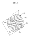
- Figure 3 is a perspective view of the filter for injection molding of the present invention;
- Figure 4 is a partial cross-sectional view of the filter in FIG. 3; and
- Figure 5 is a cross-sectional view of the nozzle in cleaning.
-
- In FIG. 1, an injection molding machine 2 is used for injection molding of plastic, and constructed of an injection unit 3, a
mold unit 4 and a mold clamping unit 5. The injection unit 3 includes ahopper 6, a heat cylinder 7, a feed screw 8, a speed reduction gear 9, anoil pressure motor 10, an injection cylinder 11,band heater 12 and anozzle 13. Thenozzle 13 is attached to an end of the heat cylinder 7. - In order to carry out injection molding with the injection molding machine 2, a recycled crushed
resin 14 is used. As already known, the used plastic articles are withdrawn into a recycling plant. In the recycling plant, a cycle of recycling processes, such as crashing, remove of foreign material, fine crashing, cleaning, drying, remove of metal and the like, is carried out to obtain the crushedresin 14. - The crushed
resin 14 is supplied in thehopper 6, and fed from thehopper 6 in the heat cylinder 7. In the heat cylinder 7, a feed screw 8 is inserted. A back end of ashaft 8a of the feed screw 8 is attached to the injection cylinder 11, and on ashaft 8a of the feed screw 8 the speed reduction gear 9 is attached. The speed reduction gear 9 is meshed with theoil pressure motor 10. Theoil pressure motor 10 drives the reduction gear 9 to rotate the feed screw 8, and the injection cylinder 11 shifts the feed screw 8 back- and forwardly in the heat cylinder 7. - The
band heater 12 is provided around the heat cylinder 7. Theband heater 12 generates the heat to melt the crushedresin 14 fed in the heat cylinder 7. Further, the friction of the crushedresin 14 causes to generate the heat, when the feed screw 8 is rotated. Accordingly, the crushedresin 14 is melted into a meltedresin 14a in the heat cylinder 7. The meltedresin 14a is fed in thenozzle 13 by slide of the feed screw 8 in forward. - The
mold unit 4 is constructed of thestationary platen 15, astationary mold 17,guide rods 18,movable platen 19, amovable mold 20 and amold support plate 21. Thestationary mold 17 is attached to thestationary platen 15, and ends of theguide rods 18 are fixedly fitted in holes (not shown) formed in thestationary platen 15. A surface of themovable platen 19 is provided with amold support plate 21 which holds to themovable mold 20. Another surface of themovable platen 19 is provided with anejector cylinder 22 for driving an ejector pin (not shown) to eject the plastic molded article from themovable mold 20. - The mold clamping unit 5 is constructed of a
base plate 24, atoggle mechanism 25 and amold clamping cylinder 26. Thebase plate 24 has holes (not shown) in which other ends of theguide rods 18 are fixedly fitted. When themold clamping cylinder 26 is driven, themovable platen 19 is slid through thetoggle mechanism 25 along theguide rod 18. - In FIG. 2, the
nozzle 13 includes anozzle case 30, anozzle head 31, afirst cap 32, asecond cap 33, apassage changer 34 and afilter 35. Thenozzle case 30 is nearly cylindrically shaped and attached to an end of the heat cylinder 7. Thenozzle head 31 is attached to an end of thenozzle case 30, and contacted to aspur bush 16 of themold unit 4 when the meltedresin 14a is fed into themold unit 4. Thepassage changer 34 shifts in directions A and B between an injection position and a cleaning position (see FIG. 5) to change passages of the meltedresin 14a. Further, in thenozzle case 30, thefirst cap 32 and thesecond cap 33 are formed aresin entrance 30a,inner passages 32a and outer passages 33b, respectively. Between thefirst cap 32 and thepassage changer 34, there is afirst connect passages 34a and asecond connect passages 34b. Further, in thenozzle head 31 aninjection passage 31a is formed. - In FIG. 3, the
filter 35 includes afilter body 35a formed of a metal plate in a cylindrical shape. Thefilter body 35a has aninner face 35b and anouter face 35c. For example, a diameter D of thefilter 35 is 45 mm, and the length L is 30mm. In thefilter body 35a, manysmall holes 35d are formed. Note that thefilter body 35a is made of hyper strong steel in order to obtain pressure-tightness for preventing the break of the injection molding machine 2 in maximum of the pressure applied by a cylinder. - In FIG. 4, a thickness "T" of the
filter body 35 is 2mm. Thesmall hole 35d has a taper shape, and a diameter D1 on theouter face 35c is 20 % smaller than a diameter D2 on theinner face 35b. The diameter D2 of thesmall hole 35d is 0.2 mm, and a ratio of T/D2 is 10. Thesmall holes 35d having this size can surely remove the foreign materials. Further, a hole pitch P is 0.5 mm, which is almost the limitation pitch of forming thesmall holes 35d. When the small holes having the diameter D2 in 0,2mm is formed at a pitch of 0.5mm in thefilter body 35a having the diameter D of 45 mm and the length L of the 30 mm, the number of thesmall holes 35d is 15414, and the total size thereof is corresponds to a hole having a diameter of 24.8mm. The total size is larger than a minimum size of cross-section of passages of the meltedresin 14a in a generally used injection molding machine or mold. Namely, the total size is larger than the cross section of the passage such as theinjection passage 31a. Accordingly, considering the resistance in the passages of thefilter 35, the pressure loss becomes lower enough. - The
small hole 35d is hardly formed in thefilter 35 with a machine processing, radiation processing and the like, considering the pitch, the number of holes, the thickness of the filter, the accuracy of forming the holes, time for processing, and the cost. Further, it may be considered to carry out the laser processing for opening the holes. However, as the energy in the laser processing is not so high, much time is necessary therefore. Accordingly, the temperature of a filter becomes higher, which causes to deform the nearest holes. - In the embodiment of the present invention, the
small holes 35d are effectively formed in a plate by the electric beam processing in which the energy is high and electric beams may be narrow. Further, in order to form taper-like shaped holes, conditions of processing should be adjusted. After processing the plate is curved to form a cylindrical shape, and both sides thereof are connected. - Operation of the present invention are explained now. In injection molding, the crushed
resin 14 is heated to become to the meltedresin 14a, and the meltedresin 14a flows into theresin entrance 30a of an end of thenozzle case 30. The meltedresin 14a in theresin entrance 30a presses thepassage changer 34 to slide in the arrowed direction A. Thereby, thefirst connect passage 34a formed at a back end of thepassage changer 34 becomes connected with theinner passage 32a of thefirst cap 32. The meltedresin 14a flowing out from thefirst cap 32 passes through thesmall holes 35d to an outside of thefilter 35. Thereby, as the foreign materials cannot pass through thesmall holes 35d, the foreign materials are removed from the meltedresin 14a used for injection molding. - After passing through the
small holes 35d, the meltedresin 14a flows through theouter passage 33a of thesecond cap 33 into thenozzle head 31. The meltedresin 14a in thenozzle head 31 passes through thespur bush 16 and is pressed to enter in thestationary mold 17. As already known, the meltedresin 14a fills in a cavity formed by thestationary mold 17 and themovable mold 20 and molded to the plastic molded article. - When the foreign materials are trapped in the
filter 35, the pressure loss becomes larger. In order to remove the foreign materials from thefilter 35, the cleaning may be carried out. In order to carry out the cleaning of thefilter 35, as shown in FIG. 5, a cleaningnozzle 40a of a cleaningplunger 40 is inserted in theinjection passage 31a of thenozzle head 31, and the cleaningplunger 40 is pressed onto thestationary platen 15. The cleaningnozzle 40a presses thepassage changer 34 to slide toward the heat cylinder 7. - When the
passage changer 34 is slid in the arrowed direction B, thefirst connect passage 34 is connected with theouter passage 32b of thefirst cap 32. Then, after feeding the meltedresin 14a from the heat cylinder 7, the meltedresin 14a passes through theouter passage 32b of thefirst cap 32 to flow into the outside of thefilter 35. Then the meltedresin 14a passes through thesmall holes 35d of thefilter 35 to flow in the inside of thefilter 35. Thereby the foreign material is removed by the flow of the meltedresin 14a in theholes 35. Thereafter, the meltedresin 14a passes through thesecond connect passage 34b of the end of thepassage changer 34, is fed in thecleaning nozzle 40a of theplunger 40, and fed out from anoutlet 40b. - As the cleaning is carried out without disassembling the
nozzle 13, the time for removing the foreign materials saves. Further, in order to carry out the cleaning, the cleaningplunger 40 is fitted in thenozzle head 31. Accordingly, the cleaning is made in a simple processing. Furthermore, as each of thesmall holes 35d is taper-like shaped, the foreign material caught with thesmall holes 35d, and it is not necessary to apply the high pressure to the crushedresin 14 in injection molding. - In the embodiment above, the
filter 35 is used in the injection molding machine for molding from crashed resin. However, thefilter 35 is also used in the injection molding machine in which the recycled pellet and the virgin resin are used. In this case, as the filter has an effect to mix the virgin plastic and the recycled plastic, a device for mixing the virgin plastic and the recycled plastic may be omitted. Note that the foreign materials are more effectively removed when thesmall holes 35d are formed so as to have smaller diameter. However, it is difficult to form thesmall holes 35d with smaller diameter. Further the cost of producing thefilter 35 becomes higher and the pressure loss in injection molding is larger. - Various changes and modifications are possible in the present invention and may be understood to be within the present invention.
Claims (7)
- A filter (35) for injection molding machine (2), said injection molding machine (2) having a nozzle (13) for injecting a melted resin (14a) in a mold (17, 20), said filter (35) comprising;
a filter body (35a) disposed in said nozzle (13), said filter body (35a) being cylindrically shaped to have first and second surfaces (35b, 35c); and
plural holes (35d) formed in said filter body (35a), said holes (35d) removing foreign materials contained in said melted resin (14a) when said melted resin (14a) flows from said first surface (35b) to said second surface (35c), and a total size of said holes (35d) being larger than a minimum size of passage (31a, 33a) of said melted resin (14a). - A filter (35) according to claim 1, wherein said holes (35a) are circular holes.
- A filter (35) according to claim 2, wherein said melted resin (14a) flows from said second surface (35c) to said first surface (35b) in filter cleaning for removing said foreign materials caught by said holes (35d).
- A filter (35) according to claim 3, wherein each of said holes (35d) is a convergent hole whose diameter is larger on said first surface (35b) than on said second surface (35c).
- A filter (35) according to claim 4, wherein said first surface (35b) is an inner surface of said filter body (35a) and said second surface (35c) is an outer surface of said filter body (35a).
- A filter (35) for injection molding machine (2), said injection molding machine (2) having a nozzle (13) for injecting a melted resin (14a) in a mold (17, 20), said filter (35) comprising;
a filter body (35a) disposed in said nozzle (13), said filter body (35a) being cylindrically shaped to have first and second surfaces (35b, 35c);
plural holes (35d) formed in said filter body (35a), said holes (35d) removing foreign materials contained in said melted resin (14a) when said melted resin (14a) flows from said first surface (35b) to said second surface (35c); and
wherein said holes (35a) are convergent holes whose diameter is smaller on said first surface (35b) than said second surface (35c). - A filter (35) according to claim 6, wherein said melted resin (14a) flows from said second surface (35c) to said first surface (35b) in filter cleaning for removing said foreign materials caught by said holes (35d).
Applications Claiming Priority (2)
| Application Number | Priority Date | Filing Date | Title |
|---|---|---|---|
| JP2001277030 | 2001-09-12 | ||
| JP2001277030A JP2003080560A (en) | 2001-09-12 | 2001-09-12 | Filter for injection molding |
Publications (2)
| Publication Number | Publication Date |
|---|---|
| EP1293324A1 true EP1293324A1 (en) | 2003-03-19 |
| EP1293324B1 EP1293324B1 (en) | 2004-11-24 |
Family
ID=19101635
Family Applications (1)
| Application Number | Title | Priority Date | Filing Date |
|---|---|---|---|
| EP02020505A Expired - Lifetime EP1293324B1 (en) | 2001-09-12 | 2002-09-12 | Filter for injection moulding machine |
Country Status (5)
| Country | Link |
|---|---|
| US (1) | US20030047506A1 (en) |
| EP (1) | EP1293324B1 (en) |
| JP (1) | JP2003080560A (en) |
| CN (1) | CN1406735A (en) |
| DE (1) | DE60202030T2 (en) |
Cited By (2)
| Publication number | Priority date | Publication date | Assignee | Title |
|---|---|---|---|---|
| CN101402240B (en) * | 2008-11-05 | 2010-06-02 | 赛纳(瑞安)机械工程有限公司 | Pu injection nozzle cleaner |
| NL1044124B1 (en) * | 2021-08-16 | 2023-02-23 | Lely Patent Nv | Method for manufacturing a milk filter, as well as such a milk filter and a milking device therewith |
Families Citing this family (10)
| Publication number | Priority date | Publication date | Assignee | Title |
|---|---|---|---|---|
| US8870563B2 (en) * | 2011-03-12 | 2014-10-28 | Husky Injection Molding Systems Ltd. | Plasticating and injection device |
| JP2014231856A (en) * | 2013-05-28 | 2014-12-11 | Ntn株式会社 | Rolling bearing |
| CN105229322B (en) | 2013-05-28 | 2019-08-16 | Ntn株式会社 | rolling bearing |
| EP3233411B1 (en) | 2014-12-15 | 2020-06-17 | Husky Injection Molding Systems Ltd. | Injection molding machine |
| CN108367478B (en) * | 2015-12-16 | 2021-05-11 | 埃克森美孚化学专利公司 | Apparatus and method for processing polymers |
| CN105500609A (en) * | 2015-12-25 | 2016-04-20 | 梁传东 | Injection nozzle component of injection molding machine |
| US10188968B2 (en) | 2016-10-31 | 2019-01-29 | Westlake Longview Corporation | Candle filter support and plate assembly for polymer melts |
| JP7135518B2 (en) | 2018-07-11 | 2022-09-13 | セイコーエプソン株式会社 | 3D printer and nozzle unit |
| AT526286B1 (en) * | 2022-07-11 | 2026-02-15 | Engel Austria Gmbh | Filter device |
| CN119635954B (en) * | 2025-02-18 | 2025-05-27 | 江苏绿能汽配科技有限公司 | An injection nozzle mechanism for processing vehicle plastic parts |
Citations (2)
| Publication number | Priority date | Publication date | Assignee | Title |
|---|---|---|---|---|
| US3767056A (en) * | 1971-08-06 | 1973-10-23 | A 1 Eng | Injection molding filter |
| JPH10217281A (en) * | 1997-02-03 | 1998-08-18 | Toyo Seikan Kaisha Ltd | Filter for injection molding |
Family Cites Families (9)
| Publication number | Priority date | Publication date | Assignee | Title |
|---|---|---|---|---|
| US4434053A (en) * | 1982-07-06 | 1984-02-28 | Osuna Diaz J M | Two-stage filter for injection molding machine |
| US5015375A (en) * | 1989-08-16 | 1991-05-14 | Mcf Systems, Inc. | Rechargeable filter assembly |
| DE3935667A1 (en) * | 1989-10-26 | 1991-05-02 | Ewikon Heizkanalsysteme Gmbh & | ELECTRICALLY HEATABLE NOZZLE FOR AN INJECTION MOLDING MACHINE, A HOT CHANNEL DEVICE OR THE LIKE. |
| JPH06206240A (en) * | 1993-01-12 | 1994-07-26 | Fuji Photo Film Co Ltd | Filter nozzle device of injection molding machine |
| US5951728A (en) * | 1994-10-03 | 1999-09-14 | Snap-Tite, Inc. | Coupling with filters |
| US20020014449A1 (en) * | 1995-06-08 | 2002-02-07 | Luis Rios | Separation systems and methods |
| JPH0932595A (en) * | 1995-07-14 | 1997-02-04 | Yanmar Agricult Equip Co Ltd | Work vehicle |
| JP3626338B2 (en) * | 1997-10-29 | 2005-03-09 | 株式会社神戸製鋼所 | Screen changer in resin molding machine |
| WO2000042233A1 (en) * | 1999-01-13 | 2000-07-20 | Cornell Research Foundation, Inc. | Monolithic fabrication of fluidic structures |
-
2001
- 2001-09-12 JP JP2001277030A patent/JP2003080560A/en active Pending
-
2002
- 2002-05-20 CN CN02120135A patent/CN1406735A/en active Pending
- 2002-09-06 US US10/235,706 patent/US20030047506A1/en not_active Abandoned
- 2002-09-12 EP EP02020505A patent/EP1293324B1/en not_active Expired - Lifetime
- 2002-09-12 DE DE60202030T patent/DE60202030T2/en not_active Expired - Lifetime
Patent Citations (2)
| Publication number | Priority date | Publication date | Assignee | Title |
|---|---|---|---|---|
| US3767056A (en) * | 1971-08-06 | 1973-10-23 | A 1 Eng | Injection molding filter |
| JPH10217281A (en) * | 1997-02-03 | 1998-08-18 | Toyo Seikan Kaisha Ltd | Filter for injection molding |
Non-Patent Citations (3)
| Title |
|---|
| "SIEBEINSATZ FUER VERSCHLUSSDUESEN", KUNSTSTOFFE, CARL HANSER VERLAG. MUNCHEN, DE, VOL. 88, NR. 6, PAGE(S) 799, ISSN: 0023-5563, XP000766379 * |
| PATENT ABSTRACTS OF JAPAN vol. 1998, no. 13 30 November 1998 (1998-11-30) * |
| ROSSBACH R: "SCHMELZEFILTER FUR DEN SPRITZGIESSER MELT FILTERS FOR INJECTION MOULDERS", KUNSTSTOFFE, CARL HANSER VERLAG. MUNCHEN, DE, VOL. 85, NR. 2, PAGE(S) 193-195, ISSN: 0023-5563, XP000487988 * |
Cited By (2)
| Publication number | Priority date | Publication date | Assignee | Title |
|---|---|---|---|---|
| CN101402240B (en) * | 2008-11-05 | 2010-06-02 | 赛纳(瑞安)机械工程有限公司 | Pu injection nozzle cleaner |
| NL1044124B1 (en) * | 2021-08-16 | 2023-02-23 | Lely Patent Nv | Method for manufacturing a milk filter, as well as such a milk filter and a milking device therewith |
Also Published As
| Publication number | Publication date |
|---|---|
| US20030047506A1 (en) | 2003-03-13 |
| DE60202030D1 (en) | 2004-12-30 |
| JP2003080560A (en) | 2003-03-19 |
| CN1406735A (en) | 2003-04-02 |
| DE60202030T2 (en) | 2005-03-31 |
| EP1293324B1 (en) | 2004-11-24 |
Similar Documents
| Publication | Publication Date | Title |
|---|---|---|
| EP1293324A1 (en) | Filter for injection moulding machine | |
| CN105008108B (en) | Injection molding device for molding and ejection forming method | |
| US4498860A (en) | Injection molding apparatus having a sprue holder with an inclined retractable ram | |
| EP2277632A1 (en) | Device for selectively depositing molten plastic materials | |
| KR20170090407A (en) | Melting vessel, injection device using same, injection molding and method for manufacturing same, and method for manufacturing inter-member junction material | |
| EP2266776A1 (en) | Method and device for producing thick-walled plastic components, in particular optical components | |
| JP5846998B2 (en) | Plasticizing device, injection device, injection molding device, extruder, and method for producing molded product | |
| CA2792890C (en) | Mold assembly with integrated melting device | |
| DE102009049675B4 (en) | Device for injection molding of molded parts from plastics | |
| JP2011062864A (en) | Structure of gas entrainment suppressing nozzle of molding machine | |
| JP5913075B2 (en) | Plasticizing apparatus, injection molding apparatus and injection molding method | |
| JP2013523497A (en) | Mold tool assembly including a resin retaining mechanism positioned against a stem tip | |
| JPH0948049A (en) | Injection molding method and injection molding apparatus for long fiber reinforced thermoplastic resin | |
| DE1919262B2 (en) | EQUIPMENT FOR SPRAYING THERMO-PLASTIC MATERIALS | |
| JPH0976328A (en) | Method and apparatus for extrusion molding long fiber-reinforced thermoplastic resin | |
| JP6522456B2 (en) | Method and apparatus for molding composite material molding | |
| JP4522943B2 (en) | Pre-plastic injection device | |
| JP3234869B2 (en) | Injection device of plunger type injection molding machine | |
| EP0614742A1 (en) | Gas-feeding nozzle | |
| JP2000158499A (en) | Method of forming screw head of injection molding machine and injection device of injection molding machine | |
| JP6118619B2 (en) | Plasticizing apparatus, molding apparatus, plasticizing method, and manufacturing method of molded article | |
| JP3283821B2 (en) | Injection device of plunger type injection molding machine | |
| JPH06328531A (en) | Injection compression molding machine | |
| JP2005288761A (en) | Injection molding machine | |
| CN106626242A (en) | One-time plastic molding mold |
Legal Events
| Date | Code | Title | Description |
|---|---|---|---|
| PUAI | Public reference made under article 153(3) epc to a published international application that has entered the european phase |
Free format text: ORIGINAL CODE: 0009012 |
|
| AK | Designated contracting states |
Designated state(s): AT BE BG CH CY CZ DE DK EE ES FI FR GB GR IE IT LI LU MC NL PT SE SK TR Kind code of ref document: A1 Designated state(s): AT BE BG CH CY CZ DE DK EE ES FI FR GB GR IE IT LI LU MC NL PT SE SK TR |
|
| AX | Request for extension of the european patent |
Extension state: AL LT LV MK RO SI |
|
| 17P | Request for examination filed |
Effective date: 20030425 |
|
| 17Q | First examination report despatched |
Effective date: 20030610 |
|
| AKX | Designation fees paid |
Designated state(s): DE NL |
|
| GRAP | Despatch of communication of intention to grant a patent |
Free format text: ORIGINAL CODE: EPIDOSNIGR1 |
|
| GRAS | Grant fee paid |
Free format text: ORIGINAL CODE: EPIDOSNIGR3 |
|
| GRAA | (expected) grant |
Free format text: ORIGINAL CODE: 0009210 |
|
| AK | Designated contracting states |
Kind code of ref document: B1 Designated state(s): DE NL |
|
| PG25 | Lapsed in a contracting state [announced via postgrant information from national office to epo] |
Ref country code: NL Free format text: LAPSE BECAUSE OF FAILURE TO SUBMIT A TRANSLATION OF THE DESCRIPTION OR TO PAY THE FEE WITHIN THE PRESCRIBED TIME-LIMIT Effective date: 20041124 |
|
| REF | Corresponds to: |
Ref document number: 60202030 Country of ref document: DE Date of ref document: 20041230 Kind code of ref document: P |
|
| REG | Reference to a national code |
Ref country code: IE Ref legal event code: FG4D |
|
| NLV1 | Nl: lapsed or annulled due to failure to fulfill the requirements of art. 29p and 29m of the patents act | ||
| PLBE | No opposition filed within time limit |
Free format text: ORIGINAL CODE: 0009261 |
|
| STAA | Information on the status of an ep patent application or granted ep patent |
Free format text: STATUS: NO OPPOSITION FILED WITHIN TIME LIMIT |
|
| 26N | No opposition filed |
Effective date: 20050825 |
|
| PGFP | Annual fee paid to national office [announced via postgrant information from national office to epo] |
Ref country code: DE Payment date: 20190827 Year of fee payment: 18 |
|
| REG | Reference to a national code |
Ref country code: DE Ref legal event code: R119 Ref document number: 60202030 Country of ref document: DE |
|
| PG25 | Lapsed in a contracting state [announced via postgrant information from national office to epo] |
Ref country code: DE Free format text: LAPSE BECAUSE OF NON-PAYMENT OF DUE FEES Effective date: 20210401 |