EP1293104B1 - Fft-based technique for adaptive directionality of dual microphones - Google Patents
Fft-based technique for adaptive directionality of dual microphones Download PDFInfo
- Publication number
- EP1293104B1 EP1293104B1 EP01933118A EP01933118A EP1293104B1 EP 1293104 B1 EP1293104 B1 EP 1293104B1 EP 01933118 A EP01933118 A EP 01933118A EP 01933118 A EP01933118 A EP 01933118A EP 1293104 B1 EP1293104 B1 EP 1293104B1
- Authority
- EP
- European Patent Office
- Prior art keywords
- domain data
- noise
- digital frequency
- digital
- canceled
- Prior art date
- Legal status (The legal status is an assumption and is not a legal conclusion. Google has not performed a legal analysis and makes no representation as to the accuracy of the status listed.)
- Expired - Lifetime
Links
Images


Classifications
-
- H—ELECTRICITY
- H04—ELECTRIC COMMUNICATION TECHNIQUE
- H04R—LOUDSPEAKERS, MICROPHONES, GRAMOPHONE PICK-UPS OR LIKE ACOUSTIC ELECTROMECHANICAL TRANSDUCERS; ELECTRIC HEARING AIDS; PUBLIC ADDRESS SYSTEMS
- H04R29/00—Monitoring arrangements; Testing arrangements
- H04R29/004—Monitoring arrangements; Testing arrangements for microphones
- H04R29/005—Microphone arrays
- H04R29/006—Microphone matching
-
- H—ELECTRICITY
- H04—ELECTRIC COMMUNICATION TECHNIQUE
- H04R—LOUDSPEAKERS, MICROPHONES, GRAMOPHONE PICK-UPS OR LIKE ACOUSTIC ELECTROMECHANICAL TRANSDUCERS; ELECTRIC HEARING AIDS; PUBLIC ADDRESS SYSTEMS
- H04R3/00—Circuits for transducers
- H04R3/005—Circuits for transducers for combining the signals of two or more microphones
-
- H—ELECTRICITY
- H04—ELECTRIC COMMUNICATION TECHNIQUE
- H04R—LOUDSPEAKERS, MICROPHONES, GRAMOPHONE PICK-UPS OR LIKE ACOUSTIC ELECTROMECHANICAL TRANSDUCERS; ELECTRIC HEARING AIDS; PUBLIC ADDRESS SYSTEMS
- H04R25/00—Electric hearing aids
- H04R25/40—Arrangements for obtaining a desired directivity characteristic
- H04R25/407—Circuits for combining signals of a plurality of transducers
Definitions
- the present invention relates to systems which use multiple microphones to reduce the noise and to enhance a target signal.
- Fig. 1 shows a simple two-microphone system that uses a fixed delay to produce a directional output.
- the first microphone 22 is separated from the second microphone 24 by distance.
- the output of the second microphone 24 is sent to a constant delay 26.
- a constant delay, d c where c is the speed of sound, is used.
- the output of the delay is subtracted from the output of the first microphone 22.
- Fig. 1B is a polar pattern of the gain of the system of Fig. 1A .
- the delay d/c causes a null for signals coming from the 180° direction.
- Different fixed delays produce polar patterns having nulls at different angles. Note that at the zero degree direction, there is very little attenuation
- the fixed directional system of Fig. 1A is effective for the case that the target signal comes from the front and the noise comes exactly from the rear, which is not always true.
- an adaptive directionality noise reduction system is highly desirable so that the system can track the moving or varying noise source. Otherwise, the noise reduction performance of the system can be greatly degraded.
- Fig. 2 is a diagram in which the output of the system is used to control a variable delay to move the null of the directional microphone to match the noise source.
- the noise reduction performance of beamforming systems greatly depends upon the number of microphones and the separation of these microphones.
- the number of microphones and distance of the microphones are strictly Limited,
- behind-the-ear hearing aids can typically use only two microphones, and the distance between these two microphones is limited to about 10mm.
- most of the available algorithms deliver a degraded noise-reduction performance.
- it is difficult to implement, in real time, such available algorithms in this application field because of the limits of hardware size, computational speed, mismatch of microphones, power supply, and other practical factors.
- US 4,653,102 discloses a directional microphone system which employs two microphones. Respective microphone signals are Fast Fourier Transformed. Low and high pass filtering is used to cancel dynamic noise. The frequency components of the incoming signals are utilized in an area and phase sorting technique to allow only pickup of the wanted sound in a well-defined area.
- WO 00/18099 discloses an interference cancelling method and apparatus for use in teleconference systems.
- the interference cancelling method and apparatus cancels an interference signal from a target signal by splitting the target signal into a plurality of band-limited target signals and beam-splits the interference signal into corresponding band-limited frequency bands.
- An adaptive filter adaptively filters each band-limited interference signal from each corresponding band-limited target signal.
- a beam selector selects beams simultaneous to improve accuracy and selects a beam having a fixed direction and a beam which rotates in direction.
- the present invention is a system in which the outputs of the first and second microphones are sampled and a discrete Fourier Transform is done on each of the sampled time domain signals.
- a further processing step takes the output of the discrete Fourier Transform and processes it to produce a noise canceled frequency-domain signal.
- the noise canceled frequency-domain signal is sent to the Inverse Discrete Fourier Transform to produce a noise canceled time domain data.
- the noise canceled frequency-domain data is a function of the first and second frequency domain data that effectively cancels noise when the noise is greater than the target signal and the noise and target signal are not in the same direction from the apparatus.
- the function provides the adaptive directonality to cancel the noise.
- the function is such that if X( ⁇ ) represents one of the first and second digital frequency-domain data and Y( ⁇ ) represents the other of the first and second digital frequency-domain data, the function is proportional to X( ⁇ )[1-
- the present invention operates by assuming that for systems in which the noise is greater than the signal, the phase of the output of one of the Discrete Fourier Transforms can be assumed to be the phase of the noise. With this assumption, and the assumption that the noise and the signal come from two deferent directions, an output function which effectively cancels the noise signal can be produced.
- the system includes a speech signal pause detector which detects pauses in the received speech signal.
- the signal during the detected pauses can be used to implement the present invention in higher signal-to-noise environments since, during the speech pauses, the noise will overwhelm the signal, and the detected "noise phase" during the pauses can be assumed to remain unchanged during the non-pause portions of the speech.
- One objective of the present invention is to provide an effective and realizable adaptive directionality system which overcomes the problems of prior directional noise reduction systems.
- Key features of the system include a simple and realizable implementation structure on the basis of FFT; the elimination of an additional delay processing unit for endfire orientation microphones; an effective solution of microphone mismatch problems; the elimination of the assumption that the target signal must be exactly straight ahead, that is, the target signal source and the noise source can be located anywhere as long as they are not located in the same direction; and no specific requirement for the geometric structure and the distance of these dual microphones.
- Fig. 3 is a diagram that shows one embodiment of the present invention.
- First and second microphones 40 and 42 are provided. If the system is used with a behind-the-ear hearing aid, the first and second microphones will typically be closely spaced together with about 10mm separation.
- the outputs of the first and second microphones can be processed. After any such processing, the signals are sent to the analog-to-digital converters 44 and 46.
- the digitized time domain signals are then sent to a Hanning window overlap block 48 and 50.
- the Hanning window selects frames of time domain data to send to the Discrete Fourier Transform blocks 52 and 54,
- the Discrete Fourier Transform (DFT) in a preferred embodiment is implemented as the Fast Fourier Transform (PPT).
- DFT Discrete Fourier Transform
- PPT Fast Fourier Transform
- the output of the DFT blocks 52 and 54 correspond to the first microphone 40 and second microphone 42, respectively.
- the data on line 58 can be considered to be either the frequency domain data X( ⁇ ) or Y( ⁇ ).
- the frequency domain data on line 60 will be Y( ⁇ ) when line 58 is X( ⁇ ), and X( ⁇ ) when the data on line 58 is Y( ⁇ ).
- the output of the processing block 56 is sent to an Inverse Discrete Fourier Transform block 62. This produces time domain data which is sent to the overlap-and-add block 64 that compensates for the Hanning window overlap blocks 48 and 50.
- the outputs of the DFT blocks 52 and 54 are bin data, which is operated on bin-by-bin by the processing block 56.
- Function Z( ⁇ ) for each bin is produced and then converted in the Inverse DFT block 62 into time domain data.
- Equation 1 or Equation 2 can provide approximately the noise-free signal under certain conditions. Note that in the present invention there is no assumed direction of the noise or the target signal other than that they do not coexist.
- the processing can be done using Equation 1 or Equation 2 where Z( ⁇ ) is the DFT of the system output Z(n).
- the conditions mainly include:
- Equation 5 ⁇ x ⁇ ⁇ ⁇ n ⁇ ⁇ y ⁇ ⁇ ⁇ n ⁇ - ⁇ nd ⁇
- This scheme can be implemented for performing two Fast Fourier Transforms (FFTs) and one Inverse Fast Fourier Transform (IFFT) for each frame of data.
- FFTs Fast Fourier Transforms
- IFFT Inverse Fast Fourier Transform
- the size of the frame will be determined by the application situations. Also, for the purpose of reducing the time aliasing problems and its artifacts, windowing processing and frame overlap are required.
- At least one FFT and one IFFT are required in other processing parts of many application systems even if this algorithm is not used.
- one FFT and one IFFT are needed so as to calculate the compression ratio in different perceptual frequency bands.
- Another example is spectral subtraction algorithm related systems, where at least one FFT and one IFFT are also required. This means that the cost of the inclusion of the proposed adaptive directionality algorithm in the application systems is only one more FFT operation.
- the structure and DSP code to perform the FFT of Y(n) can be exactly the same as those to perform the FFT of X ( n ), it can be seen that the real-time implementation of this scheme is not difficult.
- the geometric structure and distance of these dual microphones are not specified at all. They could be either broad orientation or endfire orientation.
- the endfire orientation is often used.
- a constant delay (which is about d c , d is the distance between two microphones, c is the speed of sound) is needed so as to provide a reference signal which is the difference signal X(n*T- d/c) - X(n*T) ( T is the sample interval) and contains ideally only the noise signal part.
- the distance d of microphones (for example, 12 mm in behind-the-ear hearing aids) is too short and hence the required delay (34.9 ⁇ s in this example) will be less than a sample interval (for example, the sample intervat is 62.5 ⁇ s for 16 Khz sampling rate).
- a sample interval for example, the sample intervat is 62.5 ⁇ s for 16 Khz sampling rate.
- the implementation of this constant delay is also necessary for achieving fixed directionality pattern such as hypercardiod type pattern. It can easily be seen that the present algorithm does not need this constant delay part. This advantage makes the implementation of the algorithms of the present invention even simpler.
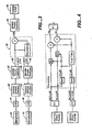
- Fig. 4 illustrates an implementation of the present invention in which an equivalent calculation is done to Equation 1.
- the advantage of this equivalent calculation is that it is done in a manner such that the data in each of the division calculation steps can be assured to be within the range -1 to 1, typically used with digital signal processors.
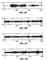
- Fig. 5 is a set of simulation results for one embodiment of the present invention.
- Fig. 5A is the desired speech.
- Fig. 5B is the noise.
- Fig. 5C is the combined signal and noise.
- Fig. 5D is a processed output.
- Fig. 6 is another set of simulation results for the method of the present invention.
- Fig. 6A is the desired speech.
- Fig. 6B is the noise.
- Fig. 6C is the combined signal and noise.
- Fig. 6D is a processed signal.
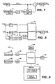
- Fig. 7 illustrates how a matching filter 71 can be added to match the output of the microphones.
- the magnitude response and phase response of two microphones are assumed to be the same.
- there is a significant mismatch in phase and magnitude between two microphones It is the significant mismatch in phase and magnitude that will result in a degraded performance of these adaptive directionality algorithms and that is one of the main reasons to prevent these available algorithms from being used in practical applications.
- the mismatch means that there is some of the target signal in the reference signal and the assumption that the reference signal contains only the noise no longer exists and hence the system will reduce not only the noise but also the desired signal.
- the matching filter 71 may be an Infinite Impulse Response (IIR) filter.
- IIR Infinite Impulse Response
- the corresponding matching filter would be more complicated, that is, a simple (with first- or second-order) filter can not effectively compensate for the phase mismatch.
- the matching filter for compensation for magnitude mismatch will introduce its own phase delay; this means that both phase mismatch and magnitude mismatch have to be taken into account simultaneously in designing the desired matching filter. All these remain unsolved problems in prior-art adaptive directionality algorithms.
- a potential shortcoming of the present scheme is that its performance will degrade in larger signal-to-noise ratio (SNR) cases.
- SNR signal-to-noise ratio
- This problem has two aspects. If the SNR is large enough, noise reduction is no longer necessary and hence the adaptive directionality can be switched off or other noise reduction methods which work well only in large SNR case can be used.
- P are the DFT output and its magnitude part during the pause period of the target speech.
- Fig. 8 illustrates the system of the present invention in which pause-detection circuitry 70 is used to detect pauses and store frequency-domain data during the pauses.
- the frequency-domain data in the speech pause is used to help obtain the phase information of the noise signal and thus improve the noise cancellation function.
- the processing block 72 uses a function of the stored frequency domain data in a speech pause to help calculate the desired noise cancelled frequency domain data.
- the phase of the detected signals is approximately equal to the noise phase even if the total SNR is relatively high.
- Fig. 9 illustrates one implementation of the present invention.
- the system of one embodiment of the present invention is implemented using a processor 80 connected to a memory or memories 82.
- the memory or memories 82 can store the DSP program 84 that can implement the FFT-based adaptive directionality program of the present invention.
- the microphone 86 and microphone 88 are connected to A/D converters 90 and 92.
- This time domain data is then sent to the processor 80 which can operate on the data similar to that shown in Figures 3, 4 , 7 and 8 above.
- the processor implementing the program 84 does the Hanning window functions, the discrete Fourier Transform functions, the noise-cancellation processing, and the Inverse Discrete Fourier Transform functions.
- the output time domain data can then be sent to a D/A converter 96.
- additional hearing-aid functions can also be implemented by the processor 80 in which the FFT-based adaptive directionality program 84 of the present invention shares processing time with other hearing-aid programs.
- the system 100 can include an input switch 98 which is polled by the processor to determine whether to use the program of the present invention or another program. In this way, when the conditions do not favor the operation of the system of the present invention (that is, when the signal is stronger than the noise or when the signal and the noise are co-located), the user can switch in another adaptive directionality program to operate in the processor 80.
Landscapes
- Health & Medical Sciences (AREA)
- General Health & Medical Sciences (AREA)
- Otolaryngology (AREA)
- Physics & Mathematics (AREA)
- Engineering & Computer Science (AREA)
- Acoustics & Sound (AREA)
- Signal Processing (AREA)
- Circuit For Audible Band Transducer (AREA)
Description
- The present invention relates to systems which use multiple microphones to reduce the noise and to enhance a target signal.
- Such systems are called beamforming systems or directional systems.
Fig. 1 shows a simple two-microphone system that uses a fixed delay to produce a directional output. Thefirst microphone 22 is separated from thesecond microphone 24 by distance. The output of thesecond microphone 24 is sent to aconstant delay 26. In one case, a constant delay,
first microphone 22.Fig. 1B is a polar pattern of the gain of the system ofFig. 1A . The delay d/c causes a null for signals coming from the 180° direction. Different fixed delays produce polar patterns having nulls at different angles. Note that at the zero degree direction, there is very little attenuation The fixed directional system ofFig. 1A is effective for the case that the target signal comes from the front and the noise comes exactly from the rear, which is not always true. - If the noise is moving or time-varying, an adaptive directionality noise reduction system is highly desirable so that the system can track the moving or varying noise source. Otherwise, the noise reduction performance of the system can be greatly degraded.
-
Fig. 2 is a diagram in which the output of the system is used to control a variable delay to move the null of the directional microphone to match the noise source. - The noise reduction performance of beamforming systems greatly depends upon the number of microphones and the separation of these microphones. In some application fields, such as heating aids, the number of microphones and distance of the microphones are strictly Limited, For example, behind-the-ear hearing aids can typically use only two microphones, and the distance between these two microphones is limited to about 10mm. In these cases, most of the available algorithms deliver a degraded noise-reduction performance. Moreover, it is difficult to implement, in real time, such available algorithms in this application field because of the limits of hardware size, computational speed, mismatch of microphones, power supply, and other practical factors. These problems prevent available algorithms, such as the closed-loop-adapted delay of
Fig. 2 , from being implemented for behind-the-ear hearing aids. -
US 4,653,102 discloses a directional microphone system which employs two microphones. Respective microphone signals are Fast Fourier Transformed. Low and high pass filtering is used to cancel dynamic noise. The frequency components of the incoming signals are utilized in an area and phase sorting technique to allow only pickup of the wanted sound in a well-defined area. -
WO 00/18099 - It is desired to have a more practical system for implementing an adaptive directional noise reduction system.
- The present invention is a system in which the outputs of the first and second microphones are sampled and a discrete Fourier Transform is done on each of the sampled time domain signals. A further processing step takes the output of the discrete Fourier Transform and processes it to produce a noise canceled frequency-domain signal. The noise canceled frequency-domain signal is sent to the Inverse Discrete Fourier Transform to produce a noise canceled time domain data.
- According to the present invention as defined in apparatus claim 1 and method claim 11, the noise canceled frequency-domain data is a function of the first and second frequency domain data that effectively cancels noise when the noise is greater than the target signal and the noise and target signal are not in the same direction from the apparatus. The function provides the adaptive directonality to cancel the noise.
- In a particular embodiment of the present invention, the function is such that if X(ω) represents one of the first and second digital frequency-domain data and Y(ω) represents the other of the first and second digital frequency-domain data, the function is proportional to X(ω)[1-|Y(ω)|/|X(ω)|].
- The present invention operates by assuming that for systems in which the noise is greater than the signal, the phase of the output of one of the Discrete Fourier Transforms can be assumed to be the phase of the noise. With this assumption, and the assumption that the noise and the signal come from two deferent directions, an output function which effectively cancels the noise signal can be produced.
- In an alternate embodiment of the present invention, the system includes a speech signal pause detector which detects pauses in the received speech signal. The signal during the detected pauses can be used to implement the present invention in higher signal-to-noise environments since, during the speech pauses, the noise will overwhelm the signal, and the detected "noise phase" during the pauses can be assumed to remain unchanged during the non-pause portions of the speech.
- One objective of the present invention is to provide an effective and realizable adaptive directionality system which overcomes the problems of prior directional noise reduction systems. Key features of the system include a simple and realizable implementation structure on the basis of FFT; the elimination of an additional delay processing unit for endfire orientation microphones; an effective solution of microphone mismatch problems; the elimination of the assumption that the target signal must be exactly straight ahead, that is, the target signal source and the noise source can be located anywhere as long as they are not located in the same direction; and no specific requirement for the geometric structure and the distance of these dual microphones. With these features, this scheme provides a new tool to implement adaptive directionality in related application fields.
-
-
Fig. 1A is a diagram of a prior-art fixed-delay directional microphone system. -
Fig. 1B is a diagram of a polar pattern illustrating the gain with respect to angle for the apparatus ofFig. 1A . -
Fig. 2 is a diagram of a prior-art adaptive directionality noise-cancellation system using a variable delay. -
Fig. 3 is a diagram of the adaptive directionality system of the present invention, using a processing block after a discrete Fourier Transform of the first and second microphone outputs. -
Fig. 4 is a diagram of one implementation of the apparatus ofFig. 3 . -
Figs. 5 and6 are simulations illustrating the operation of the system of one embodiment of the present invention. -
Fig. 7 is a diagram that illustrates an embodiment of the present invention using a matching filter. -
Fig. 8 is a diagram that illustrates the operation of one embodiment of the present invention using pause detection. -
Fig. 9 is a diagram that illustrates an embodiment of the present invention wherein the adaptive directionality system of the present invention is implemented on a digital signal processor. -
Fig. 3 is a diagram that shows one embodiment of the present invention. First andsecond microphones digital converters window overlap block first microphone 40 andsecond microphone 42, respectively. In theprocessing block 56, the data online 58 can be considered to be either the frequency domain data X(ω) or Y(ω). Thus, the frequency domain data online 60 will be Y(ω) whenline 58 is X(ω), and X(ω) when the data online 58 is Y(ω). In one embodiment, the processing produces an output Z(ω) given by (Equation 1):
Alternately the processing output can be given by (Equation 2):
The output of theprocessing block 56 is sent to an Inverse DiscreteFourier Transform block 62. This produces time domain data which is sent to the overlap-and-add block 64 that compensates for the Hanning window overlap blocks 48 and 50. - In one embodiment, the outputs of the DFT blocks 52 and 54 are bin data, which is operated on bin-by-bin by the
processing block 56. Function Z(ω) for each bin is produced and then converted in theInverse DFT block 62 into time domain data. - For a dual-microphone system, let us denote the received signals at one microphone and the other microphone as X(n) and Y(n), their DFTs as X(ω) and Y(w), respectively. The scheme is shown in
Fig. 3 . It will be proven that either of Equation 1 orEquation 2 can provide approximately the noise-free signal under certain conditions. Note that in the present invention there is no assumed direction of the noise or the target signal other than that they do not coexist. The processing can be done using Equation 1 orEquation 2 where Z(ω) is the DFT of the system output Z(n). The conditions mainly include: - 1. The magnitude responses of two microphones should be the same.
- 2. The power of the noise is larger than that of the desired signal.
- 1. |X(ω)|, ψx(ω), and [Y(ω)|, ψy(ω) are the magnitude and phase parts of X(ω) and Y(ω), respectively.
- 2. |S(ω)|, ψs(ω), and |N(ω)|, ψn(ω) are the magnitude and phase parts of the desired signal S(ω) and the noise N(ω) at the first microphone, respectively.
- 3. ψsd(ω) and ψnd(ω) are the phase delay of the desired signal and noise in the second microphone, respectively, which includes all phase delay, that is, the wave transmission delay, phase mismatch of two microphone, etc.
- Because the noise power is larger than the signal power, we have the following approximations (Equation 5):


Substituting Equation 5 into Equation 1 yields:
- This scheme can be implemented for performing two Fast Fourier Transforms (FFTs) and one Inverse Fast Fourier Transform (IFFT) for each frame of data. The size of the frame will be determined by the application situations. Also, for the purpose of reducing the time aliasing problems and its artifacts, windowing processing and frame overlap are required.
- Note that, typically, at least one FFT and one IFFT are required in other processing parts of many application systems even if this algorithm is not used. For example, in some digital hearing aids, one FFT and one IFFT are needed so as to calculate the compression ratio in different perceptual frequency bands. Another example is spectral subtraction algorithm related systems, where at least one FFT and one IFFT are also required. This means that the cost of the inclusion of the proposed adaptive directionality algorithm in the application systems is only one more FFT operation. Together with the fact that the structure and DSP code to perform the FFT of Y(n) can be exactly the same as those to perform the FFT of X(n), it can be seen that the real-time implementation of this scheme is not difficult.
- In the present scheme, the geometric structure and distance of these dual microphones are not specified at all. They could be either broad orientation or endfire orientation. For hearing-aid applications, the endfire orientation is often used. With the endfire orientation, if Griffiths-Jim's type adaptive directionality algorithms are employed, a constant delay (which is about

-
Fig. 4 illustrates an implementation of the present invention in which an equivalent calculation is done to Equation 1. This equivalent calculation is in the form
The advantage of this equivalent calculation is that it is done in a manner such that the data in each of the division calculation steps can be assured to be within the range -1 to 1, typically used with digital signal processors. -
Fig. 5 is a set of simulation results for one embodiment of the present invention.Fig. 5A is the desired speech.Fig. 5B is the noise.Fig. 5C is the combined signal and noise.Fig. 5D is a processed output. -
Fig. 6 is another set of simulation results for the method of the present invention.Fig. 6A is the desired speech.Fig. 6B is the noise.Fig. 6C is the combined signal and noise.Fig. 6D is a processed signal. -
Fig. 7 illustrates how a matchingfilter 71 can be added to match the output of the microphones. In most available adaptive directionality algorithms, the magnitude response and phase response of two microphones are assumed to be the same. However, in practical applications, there is a significant mismatch in phase and magnitude between two microphones. It is the significant mismatch in phase and magnitude that will result in a degraded performance of these adaptive directionality algorithms and that is one of the main reasons to prevent these available algorithms from being used in practical applications. For example, in the Griffiths-Jim's type adaptive directionality algorithms, the mismatch means that there is some of the target signal in the reference signal and the assumption that the reference signal contains only the noise no longer exists and hence the system will reduce not only the noise but also the desired signal. Because it is not difficult to measure the mismatch of magnitude responses of two microphones, we can include a matching filter in either of two channels so as to compensate for the mismatch in magnitude response as shown inFig. 7 . The matchingfilter 71 may be an Infinite Impulse Response (IIR) filter. With careful design, a first-order IIR can compensate for the mismatch in magnitude response very well. As a result, mismatch problems in magnitude can be effectively overcome by this idea. However, concerning the phase mismatch, the problem will become more complicated and serious. First, it is difficult to measure phase mismatch for each device in application situations. Second, even if the phase mismatch measurement is available, the corresponding matching filter would be more complicated, that is, a simple (with first- or second-order) filter can not effectively compensate for the phase mismatch. In addition, the matching filter for compensation for magnitude mismatch will introduce its own phase delay; this means that both phase mismatch and magnitude mismatch have to be taken into account simultaneously in designing the desired matching filter. All these remain unsolved problems in prior-art adaptive directionality algorithms. - In the present scheme, these problems are effectively overcome. First, the magnitude mismatch of two microphones can be overcome by employing the
magnitude matching filter 71. Second, as mentioned above, ψnd(ω) has included all the phase delay parts no matter where they come from, so we do not encounter the phase mismatch problem at all in the present scheme. - In most available adaptive directionality algorithms, there is an assumption that the desired speech source is located exactly straight ahead. This assumption cannot be exactly met in some applications or can result in some inconvenience for users. For example, in some hearing aid applications, this assumption means that the listener must be always towards straight the target speech source, otherwise, the system performance will greatly degrade. However, in the present scheme, this assumption has been eliminated, that is, the target speech source and noise source can be located anywhere as long as they are not located in the same direction.
- A potential shortcoming of the present scheme is that its performance will degrade in larger signal-to-noise ratio (SNR) cases. This is a common problem in related adaptive directionality schemers. This problem has two aspects. If the SNR is large enough, noise reduction is no longer necessary and hence the adaptive directionality can be switched off or other noise reduction methods which work well only in large SNR case can be used. In the other aspect, we can first use the detection of the speech pause and estimate the related phase during this pause period and then modify Equation 1 to

where X(ω)P, Y(ω)P and |X(ω)|P, |Y(ω)|P are the DFT output and its magnitude part during the pause period of the target speech. This modification can overcome the above shortcoming but the cost is more computationally complex due to the inclusion of the detection of the speech pause. -
Fig. 8 illustrates the system of the present invention in which pause-detection circuitry 70 is used to detect pauses and store frequency-domain data during the pauses. The frequency-domain data in the speech pause is used to help obtain the phase information of the noise signal and thus improve the noise cancellation function. - Note that the
processing block 72 uses a function of the stored frequency domain data in a speech pause to help calculate the desired noise cancelled frequency domain data. During the target speech pause, the phase of the detected signals is approximately equal to the noise phase even if the total SNR is relatively high. -
Fig. 9 illustrates one implementation of the present invention. The system of one embodiment of the present invention is implemented using aprocessor 80 connected to a memory ormemories 82. The memory ormemories 82 can store theDSP program 84 that can implement the FFT-based adaptive directionality program of the present invention. Themicrophone 86 andmicrophone 88 are connected to A/D converters processor 80 which can operate on the data similar to that shown inFigures 3, 4 ,7 and 8 above. In a preferred embodiment, the processor implementing theprogram 84 does the Hanning window functions, the discrete Fourier Transform functions, the noise-cancellation processing, and the Inverse Discrete Fourier Transform functions. The output time domain data can then be sent to a D/A converter 96. Note that additional hearing-aid functions can also be implemented by theprocessor 80 in which the FFT-basedadaptive directionality program 84 of the present invention shares processing time with other hearing-aid programs. - In one embodiment of the present invention, the
system 100 can include aninput switch 98 which is polled by the processor to determine whether to use the program of the present invention or another program. In this way, when the conditions do not favor the operation of the system of the present invention (that is, when the signal is stronger than the noise or when the signal and the noise are co-located), the user can switch in another adaptive directionality program to operate in theprocessor 80. - Several alternative methods with the same function and working principles can be obtained by use of some modifications which mainly include the following respects:
- 1. A matching filter could be added in either of dual microphones before performing FFT so as to conpensate for the magnitude mismatch of two microphones as
Fig. 7 shows. The matching filter can be either an FIR filter or an IIR filter. - 2. Direct summation of Equation 1 with
Equation 2 for the purpose of further increasing the output SNR, that is,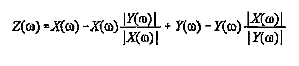
- 3. In hearing aid applications, in one embodiment the output provided by Equation 1 is provided to one ear and the output provided by
Equation 2 is provided to the other ear so as to achieve binaural results. - 4. Equation 1 and
Equation 2 are equivalent to the following, respectively:
or
which can avoid the problem that the nominator is larger than the denominator in hardware implementation of the division. - 5. Equation 1 and
Equation 2 can also be modified to the following, respectively, with the inclusion of the detection of the speech pause:

where X(ω)p, Y(ω)p , and |X(ω)|p, |Y(ω)|p are the DFT and its magnitude part of X(n) and Y(n) during the pause period of the target speech.


Claims (17)
- An apparatus comprising:a first microphone (40);a second microphone (42);at least one analog-to-digital converter (44, 46) adapted to convert first and second analog microphone outputs into first and second digital time-domain data; andprocessing means receiving the digital time domain data, the processing means including,a first Discrete Fourier Transform block (52) converting the first digital time-domain data into a first digital frequency-domain data (X(ω), Y(ω)),a second Discrete Fourier Transform block (52) converting the second digital time-domain data into a second digital frequency-domain data(Y(ω), X(ω)),a noise canceling processing block (56) operating on the first and second digital frequency-domain data (X(ω), Y(ω)) to produce noise-canceled digital frequency-domain data (Z(ω)). the noise-canceled digital frequency-domain data (Z(ω)) being a function of the first and second digital frequency-domain data (X(ω), Y(ω)), andan inverse Discrete Fourier Transform block (62) converting the noise-canceled digital frequency-domain data (Z(ω)) into noise-canceled digital time-domain data, characterized in thatif X(ω) represents one of the first and second digital freguency-domain data and Y(ω) represents the other of the first and second digital frequency-domain data, and X(ω) is the sum of a desired signal S(ω) and a noise signal N(ω),the noise-canceled digital frequency-domain data (Z(ω)) are given by X(ω)[1-|Y(ω)|/|X(ω)|] and noise canceling is performed under the condition that the power of the noise N(ω) is greater than that of the desired signal S(ω) and the noise N(ω) and desired signal S(ω) do not arrive at the apparatus from the same direction, the function providing adaptive directionality to cancel the noise N(ω).
- The apparatus of claim 1, wherein the first and second digital frequency-domain data and noise-canceled digital frequency-domain data each includes real and imaginary parts, wherein XIa(ω) represents the real portion of one of the first and second digital frequency-domain data, Xfa(ω) represents the imaginary portion of the one of the first and second digital frequency-domain data, Yra(ω) represents the real portion of the other of the first and second digital frequency-domain data, YIm(ω) represents the imaginary portion of the other of the first and second digital frequency-domain data, wherein the function is implemented by calculating [Xra(ω)/|X(ω)| + jXim(ω)/|X(ω)|]·[|X(ω)|-|Y(ω)|].
- The apparatus of claim 1, further comprising elements to detect pauses in a speech signal.
- The apparatus of claim 3, wherein if X(ω) represents one of the first and second digital frequency-domain data, Y(ω) represents the other of the first and second digital frequency-domain data, Xp(ω) represents the one of the first and second digital frequency-domain data during a pause and Yp(ω) represents the other of the first and second digital frequency-domain data during the pause, and the function is proportional to X(ω)- Y(ω)[|Y(ω)|p/|X(ω)|p][Xp(ω) /Yp(ω)].
- The apparatus of claim 1 further comprising windowing overlap block, (48,50).
- The apparatus of claim 5 wherein the windowing overlap block (48, 50) is a Flanning window block.
- The apparatus of claim 1 wherein the discrete Fourier Transform blocks (52, 54) are Fast Fourier Transform blocks.
- The apparatus of claim 1, further comprising additional heating-aid processing functions.
- The apparatus of Claim 1 wherein the processing means comprises a processor adapted to implement software code so as to implement the discrete Fourier Transform blocks (52, 54), the noise canceling processing block (56) and the Inverse discrete Fourier Transform block (62).
- The apparatus of Claim 9 wherein the processor comprises a digital signal processor.
- A method comprising :converting first and second analog microphone outputs from first and second microphones into first and second digital time-domain data;producing noise-canceled digital frequency-domain data Z(ω) from the first and second digital frequency-domain data, (X(ω), Y(ω) the noise-canceled digital frequency-domain
data Z(ω) being a function of the first and second digital frequency-domain, data, X(ω), Y(ω) andconverting the noise-canceled digital frequency-domain data into noise-canceled digital time-domain data,characterized thatif X(ω) represents one of the first and second digital freguency-domain data and Y(ω) represents the other of the first and second digital frequency-domain data, and X(ω) is the sum of a desired signal S(ω) and a noise signal N(ω),the noise-canceled digital frequency-domain data (Z(ω)) are given by X(ω)[1-|Y(ω)|/|X(ω)|] and noise canceling is performed under the condition that the power of the noise N(ω) is greater than that of the desired signal S(ω) and the noise N(ω) and desired signal S(ω) do not arrive at the apparatus from the same direction, the function providing adaptive directionality to cancel the noise N(ω). - The method of claim 11, wherein the first and second digital frequency-domain data and noise-canceled digital frequency-domain data each includes real and imaginary parts, wherein Xra(ω) represents the real portion of one of the first and second digital frequency-domain data, Xtm(ω) represents the imaginary portion of the one of the first and second digital frequency-domain data, Yrn(ω) represents the real portion of the other of the first and second digital frequency-domain data, Yim(ω) represents the imaginary portion of the other of the first and second digital frequency-domain data, where Z(ω) is determined by calculating [Xro(ω)/X(ω)| +jXim(ω)/|X(ω)|][X(ω)|-|Y(ω)].
- The method of claim 11 further comprising detecting panses in a speech signal.
- The method of claim 13, wherein if X(ω) represents one of the first and second digital frequency-domain data, Y(ω) represents the other of the first and second digital frequency-domain data, Xp(ω) represents the one of the first and second digital frequency-domain data during the pause and Yp(ω) represents the other of the first and second digital frequency-domain data during the pause, and the function in proportional to X(ω)-Y(ω)[|Y(ω)|p/[X(ω)|p][Xp(ω) /Y p(ω)].
- The method of Claim 11 wherein the processing further comprises the step of doing a windowing after the first converting step and before the producing step.
- The method of Claim 11 wherein the windowing overlap step includes doing a Hanning windowing.
- The method of Claim 11 further comprising additional hearing aid
Applications Claiming Priority (3)
| Application Number | Priority Date | Filing Date | Title |
|---|---|---|---|
| US09/567,860 US6668062B1 (en) | 2000-05-09 | 2000-05-09 | FFT-based technique for adaptive directionality of dual microphones |
| US567860 | 2000-05-09 | ||
| PCT/US2001/014653 WO2001087010A1 (en) | 2000-05-09 | 2001-05-03 | Fft-based technique for adaptive directionality of dual microphones |
Publications (3)
| Publication Number | Publication Date |
|---|---|
| EP1293104A1 EP1293104A1 (en) | 2003-03-19 |
| EP1293104A4 EP1293104A4 (en) | 2009-03-25 |
| EP1293104B1 true EP1293104B1 (en) | 2013-03-13 |
Family
ID=24268933
Family Applications (1)
| Application Number | Title | Priority Date | Filing Date |
|---|---|---|---|
| EP01933118A Expired - Lifetime EP1293104B1 (en) | 2000-05-09 | 2001-05-03 | Fft-based technique for adaptive directionality of dual microphones |
Country Status (5)
| Country | Link |
|---|---|
| US (1) | US6668062B1 (en) |
| EP (1) | EP1293104B1 (en) |
| AU (1) | AU2001259567A1 (en) |
| DK (1) | DK1293104T3 (en) |
| WO (1) | WO2001087010A1 (en) |
Families Citing this family (67)
| Publication number | Priority date | Publication date | Assignee | Title |
|---|---|---|---|---|
| US20030179888A1 (en) * | 2002-03-05 | 2003-09-25 | Burnett Gregory C. | Voice activity detection (VAD) devices and methods for use with noise suppression systems |
| US8019091B2 (en) | 2000-07-19 | 2011-09-13 | Aliphcom, Inc. | Voice activity detector (VAD) -based multiple-microphone acoustic noise suppression |
| JP3940662B2 (en) * | 2001-11-22 | 2007-07-04 | 株式会社東芝 | Acoustic signal processing method, acoustic signal processing apparatus, and speech recognition apparatus |
| WO2007106399A2 (en) | 2006-03-10 | 2007-09-20 | Mh Acoustics, Llc | Noise-reducing directional microphone array |
| US9066186B2 (en) | 2003-01-30 | 2015-06-23 | Aliphcom | Light-based detection for acoustic applications |
| US9099094B2 (en) | 2003-03-27 | 2015-08-04 | Aliphcom | Microphone array with rear venting |
| US7359929B2 (en) * | 2003-11-12 | 2008-04-15 | City University Of Hong Kong | Fast solution of integral equations representing wave propagation |
| US8401212B2 (en) | 2007-10-12 | 2013-03-19 | Earlens Corporation | Multifunction system and method for integrated hearing and communication with noise cancellation and feedback management |
| US7867160B2 (en) | 2004-10-12 | 2011-01-11 | Earlens Corporation | Systems and methods for photo-mechanical hearing transduction |
| US8295523B2 (en) | 2007-10-04 | 2012-10-23 | SoundBeam LLC | Energy delivery and microphone placement methods for improved comfort in an open canal hearing aid |
| US7668325B2 (en) | 2005-05-03 | 2010-02-23 | Earlens Corporation | Hearing system having an open chamber for housing components and reducing the occlusion effect |
| US20060133621A1 (en) * | 2004-12-22 | 2006-06-22 | Broadcom Corporation | Wireless telephone having multiple microphones |
| US7983720B2 (en) * | 2004-12-22 | 2011-07-19 | Broadcom Corporation | Wireless telephone with adaptive microphone array |
| US8509703B2 (en) * | 2004-12-22 | 2013-08-13 | Broadcom Corporation | Wireless telephone with multiple microphones and multiple description transmission |
| US20060147063A1 (en) * | 2004-12-22 | 2006-07-06 | Broadcom Corporation | Echo cancellation in telephones with multiple microphones |
| US20070116300A1 (en) * | 2004-12-22 | 2007-05-24 | Broadcom Corporation | Channel decoding for wireless telephones with multiple microphones and multiple description transmission |
| US20060135085A1 (en) * | 2004-12-22 | 2006-06-22 | Broadcom Corporation | Wireless telephone with uni-directional and omni-directional microphones |
| US7646876B2 (en) * | 2005-03-30 | 2010-01-12 | Polycom, Inc. | System and method for stereo operation of microphones for video conferencing system |
| US20070047742A1 (en) * | 2005-08-26 | 2007-03-01 | Step Communications Corporation, A Nevada Corporation | Method and system for enhancing regional sensitivity noise discrimination |
| US7619563B2 (en) * | 2005-08-26 | 2009-11-17 | Step Communications Corporation | Beam former using phase difference enhancement |
| US20070047743A1 (en) * | 2005-08-26 | 2007-03-01 | Step Communications Corporation, A Nevada Corporation | Method and apparatus for improving noise discrimination using enhanced phase difference value |
| US7415372B2 (en) * | 2005-08-26 | 2008-08-19 | Step Communications Corporation | Method and apparatus for improving noise discrimination in multiple sensor pairs |
| US7472041B2 (en) | 2005-08-26 | 2008-12-30 | Step Communications Corporation | Method and apparatus for accommodating device and/or signal mismatch in a sensor array |
| US20070050441A1 (en) * | 2005-08-26 | 2007-03-01 | Step Communications Corporation,A Nevada Corporati | Method and apparatus for improving noise discrimination using attenuation factor |
| US7436188B2 (en) * | 2005-08-26 | 2008-10-14 | Step Communications Corporation | System and method for improving time domain processed sensor signals |
| US8130977B2 (en) * | 2005-12-27 | 2012-03-06 | Polycom, Inc. | Cluster of first-order microphones and method of operation for stereo input of videoconferencing system |
| US20070237338A1 (en) * | 2006-04-11 | 2007-10-11 | Alon Konchitsky | Method and apparatus to improve voice quality of cellular calls by noise reduction using a microphone receiving noise and speech from two air pipes |
| US20070213010A1 (en) * | 2006-03-13 | 2007-09-13 | Alon Konchitsky | System, device, database and method for increasing the capacity and call volume of a communications network |
| US20070263847A1 (en) * | 2006-04-11 | 2007-11-15 | Alon Konchitsky | Environmental noise reduction and cancellation for a cellular telephone communication device |
| US20070237339A1 (en) * | 2006-04-11 | 2007-10-11 | Alon Konchitsky | Environmental noise reduction and cancellation for a voice over internet packets (VOIP) communication device |
| WO2007110807A2 (en) * | 2006-03-24 | 2007-10-04 | Koninklijke Philips Electronics N.V. | Data processing for a waerable apparatus |
| US20080152167A1 (en) * | 2006-12-22 | 2008-06-26 | Step Communications Corporation | Near-field vector signal enhancement |
| US9343079B2 (en) * | 2007-06-15 | 2016-05-17 | Alon Konchitsky | Receiver intelligibility enhancement system |
| US8428661B2 (en) | 2007-10-30 | 2013-04-23 | Broadcom Corporation | Speech intelligibility in telephones with multiple microphones |
| DE102008046040B4 (en) * | 2008-09-05 | 2012-03-15 | Siemens Medical Instruments Pte. Ltd. | Method for operating a hearing device with directivity and associated hearing device |
| KR101568451B1 (en) | 2008-06-17 | 2015-11-11 | 이어렌즈 코포레이션 | Optical electro-mechanical hearing devices with combined power and signal architectures |
| WO2009155358A1 (en) | 2008-06-17 | 2009-12-23 | Earlens Corporation | Optical electro-mechanical hearing devices with separate power and signal components |
| US8396239B2 (en) | 2008-06-17 | 2013-03-12 | Earlens Corporation | Optical electro-mechanical hearing devices with combined power and signal architectures |
| WO2014062152A1 (en) * | 2012-10-15 | 2014-04-24 | Mh Acoustics, Llc | Noise-reducing directional microphone array |
| CN102301747B (en) | 2008-09-22 | 2016-09-07 | 依耳乐恩斯公司 | Balanced armature device and method for hearing |
| DK2438768T3 (en) | 2009-06-05 | 2016-06-06 | Earlens Corp | Optically coupled acoustically mellemøreimplantatindretning |
| US9544700B2 (en) | 2009-06-15 | 2017-01-10 | Earlens Corporation | Optically coupled active ossicular replacement prosthesis |
| WO2010148345A2 (en) | 2009-06-18 | 2010-12-23 | SoundBeam LLC | Eardrum implantable devices for hearing systems and methods |
| AU2010263045A1 (en) | 2009-06-18 | 2012-02-09 | Earlens Corporation | Optically coupled cochlear implant systems and methods |
| CN102598715B (en) | 2009-06-22 | 2015-08-05 | 伊尔莱茵斯公司 | optical coupling bone conduction device, system and method |
| US10555100B2 (en) | 2009-06-22 | 2020-02-04 | Earlens Corporation | Round window coupled hearing systems and methods |
| WO2010151636A2 (en) | 2009-06-24 | 2010-12-29 | SoundBeam LLC | Optical cochlear stimulation devices and methods |
| WO2010151647A2 (en) | 2009-06-24 | 2010-12-29 | SoundBeam LLC | Optically coupled cochlear actuator systems and methods |
| JP5310494B2 (en) * | 2009-11-09 | 2013-10-09 | 日本電気株式会社 | Signal processing method, information processing apparatus, and signal processing program |
| DE102009052992B3 (en) * | 2009-11-12 | 2011-03-17 | Institut für Rundfunktechnik GmbH | Method for mixing microphone signals of a multi-microphone sound recording |
| CN102111697B (en) * | 2009-12-28 | 2015-03-25 | 歌尔声学股份有限公司 | Method and device for controlling noise reduction of microphone array |
| JP5672770B2 (en) | 2010-05-19 | 2015-02-18 | 富士通株式会社 | Microphone array device and program executed by the microphone array device |
| EP3758394A1 (en) | 2010-12-20 | 2020-12-30 | Earlens Corporation | Anatomically customized ear canal hearing apparatus |
| US9173025B2 (en) | 2012-02-08 | 2015-10-27 | Dolby Laboratories Licensing Corporation | Combined suppression of noise, echo, and out-of-location signals |
| US8712076B2 (en) | 2012-02-08 | 2014-04-29 | Dolby Laboratories Licensing Corporation | Post-processing including median filtering of noise suppression gains |
| US10034103B2 (en) | 2014-03-18 | 2018-07-24 | Earlens Corporation | High fidelity and reduced feedback contact hearing apparatus and methods |
| WO2016011044A1 (en) | 2014-07-14 | 2016-01-21 | Earlens Corporation | Sliding bias and peak limiting for optical hearing devices |
| US9924276B2 (en) | 2014-11-26 | 2018-03-20 | Earlens Corporation | Adjustable venting for hearing instruments |
| US9786262B2 (en) | 2015-06-24 | 2017-10-10 | Edward Villaume | Programmable noise reducing, deadening, and cancelation devices, systems and methods |
| WO2017059218A1 (en) | 2015-10-02 | 2017-04-06 | Earlens Corporation | Wearable customized ear canal apparatus |
| US11350226B2 (en) | 2015-12-30 | 2022-05-31 | Earlens Corporation | Charging protocol for rechargeable hearing systems |
| US10492010B2 (en) | 2015-12-30 | 2019-11-26 | Earlens Corporations | Damping in contact hearing systems |
| US10178483B2 (en) | 2015-12-30 | 2019-01-08 | Earlens Corporation | Light based hearing systems, apparatus, and methods |
| EP3510796B1 (en) | 2016-09-09 | 2026-01-14 | Earlens Corporation | Contact hearing systems, apparatus and methods |
| WO2018093733A1 (en) | 2016-11-15 | 2018-05-24 | Earlens Corporation | Improved impression procedure |
| WO2019173470A1 (en) | 2018-03-07 | 2019-09-12 | Earlens Corporation | Contact hearing device and retention structure materials |
| WO2019199680A1 (en) | 2018-04-09 | 2019-10-17 | Earlens Corporation | Dynamic filter |
Family Cites Families (11)
| Publication number | Priority date | Publication date | Assignee | Title |
|---|---|---|---|---|
| US4653102A (en) * | 1985-11-05 | 1987-03-24 | Position Orientation Systems | Directional microphone system |
| JP3279612B2 (en) | 1991-12-06 | 2002-04-30 | ソニー株式会社 | Noise reduction device |
| FR2687496B1 (en) * | 1992-02-18 | 1994-04-01 | Alcatel Radiotelephone | METHOD FOR REDUCING ACOUSTIC NOISE IN A SPEAKING SIGNAL. |
| US5400409A (en) | 1992-12-23 | 1995-03-21 | Daimler-Benz Ag | Noise-reduction method for noise-affected voice channels |
| FR2700055B1 (en) * | 1992-12-30 | 1995-01-27 | Sextant Avionique | Method for denoising vector speech and device for implementing it. |
| US5581620A (en) | 1994-04-21 | 1996-12-03 | Brown University Research Foundation | Methods and apparatus for adaptive beamforming |
| CA2157418C (en) | 1994-09-01 | 1999-07-13 | Osamu Hoshuyama | Beamformer using coefficient restrained adaptive filters for detecting interference signals |
| JP2758846B2 (en) | 1995-02-27 | 1998-05-28 | 埼玉日本電気株式会社 | Noise canceller device |
| US5825898A (en) | 1996-06-27 | 1998-10-20 | Lamar Signal Processing Ltd. | System and method for adaptive interference cancelling |
| US6178248B1 (en) | 1997-04-14 | 2001-01-23 | Andrea Electronics Corporation | Dual-processing interference cancelling system and method |
| US6049607A (en) * | 1998-09-18 | 2000-04-11 | Lamar Signal Processing | Interference canceling method and apparatus |
-
2000
- 2000-05-09 US US09/567,860 patent/US6668062B1/en not_active Expired - Fee Related
-
2001
- 2001-05-03 DK DK01933118.0T patent/DK1293104T3/en active
- 2001-05-03 AU AU2001259567A patent/AU2001259567A1/en not_active Abandoned
- 2001-05-03 EP EP01933118A patent/EP1293104B1/en not_active Expired - Lifetime
- 2001-05-03 WO PCT/US2001/014653 patent/WO2001087010A1/en not_active Ceased
Also Published As
| Publication number | Publication date |
|---|---|
| US6668062B1 (en) | 2003-12-23 |
| DK1293104T3 (en) | 2013-05-21 |
| EP1293104A4 (en) | 2009-03-25 |
| AU2001259567A1 (en) | 2001-11-20 |
| EP1293104A1 (en) | 2003-03-19 |
| WO2001087010A1 (en) | 2001-11-15 |
Similar Documents
| Publication | Publication Date | Title |
|---|---|---|
| US6668062B1 (en) | FFT-based technique for adaptive directionality of dual microphones | |
| EP3542547B1 (en) | Adaptive beamforming | |
| EP2183853B1 (en) | Robust two microphone noise suppression system | |
| EP3566461B1 (en) | Method and apparatus for audio capture using beamforming | |
| US6222927B1 (en) | Binaural signal processing system and method | |
| CN101510426B (en) | Method and system for eliminating noise | |
| RU2185710C2 (en) | Method and acoustic transducer for electronic generation of directivity pattern for acoustic signals | |
| EP1278395B1 (en) | Second-order adaptive differential microphone array | |
| US7099821B2 (en) | Separation of target acoustic signals in a multi-transducer arrangement | |
| US6002776A (en) | Directional acoustic signal processor and method therefor | |
| JP4378170B2 (en) | Acoustic device, system and method based on cardioid beam with desired zero point | |
| EP3566462B1 (en) | Audio capture using beamforming | |
| EP3545691B1 (en) | Far field sound capturing | |
| NO341066B1 (en) | Blind Signal Extraction | |
| US20190035382A1 (en) | Adaptive post filtering | |
| WO2018127483A1 (en) | Audio capture using beamforming | |
| EP1065909A2 (en) | Noise canceling microphone array | |
| JP2010152107A (en) | Device and program for extraction of target sound | |
| Wang et al. | A Novel Speech Enhancement System Based on the Coherence-Based Algorithm and the Differential Beamforming | |
| Zhang et al. | A frequency domain approach for speech enhancement with directionality using compact microphone array. | |
| Luo et al. | Fast computation of the target signal phase in noisy environments |
Legal Events
| Date | Code | Title | Description |
|---|---|---|---|
| PUAI | Public reference made under article 153(3) epc to a published international application that has entered the european phase |
Free format text: ORIGINAL CODE: 0009012 |
|
| 17P | Request for examination filed |
Effective date: 20021209 |
|
| AK | Designated contracting states |
Kind code of ref document: A1 Designated state(s): AT BE CH CY DE DK ES FI FR GB GR IE IT LI LU MC NL PT SE TR |
|
| AX | Request for extension of the european patent |
Extension state: AL LT LV MK RO SI |
|
| RIN1 | Information on inventor provided before grant (corrected) |
Inventor name: LUO, FA-LONG Inventor name: EDWARDS, BRENT Inventor name: MICHAEL, NICK Inventor name: YANG, JUN |
|
| A4 | Supplementary search report drawn up and despatched |
Effective date: 20090219 |
|
| RAP1 | Party data changed (applicant data changed or rights of an application transferred) |
Owner name: GN RESOUND A/S |
|
| 17Q | First examination report despatched |
Effective date: 20090818 |
|
| REG | Reference to a national code |
Ref country code: DE Ref legal event code: R079 Ref document number: 60147765 Country of ref document: DE Free format text: PREVIOUS MAIN CLASS: H04R0003000000 Ipc: H04R0029000000 |
|
| GRAP | Despatch of communication of intention to grant a patent |
Free format text: ORIGINAL CODE: EPIDOSNIGR1 |
|
| GRAJ | Information related to disapproval of communication of intention to grant by the applicant or resumption of examination proceedings by the epo deleted |
Free format text: ORIGINAL CODE: EPIDOSDIGR1 |
|
| RIC1 | Information provided on ipc code assigned before grant |
Ipc: H04R 3/00 20060101ALI20120214BHEP Ipc: H04R 29/00 20060101AFI20120214BHEP |
|
| GRAC | Information related to communication of intention to grant a patent modified |
Free format text: ORIGINAL CODE: EPIDOSCIGR1 |
|
| GRAP | Despatch of communication of intention to grant a patent |
Free format text: ORIGINAL CODE: EPIDOSNIGR1 |
|
| GRAC | Information related to communication of intention to grant a patent modified |
Free format text: ORIGINAL CODE: EPIDOSCIGR1 |
|
| GRAP | Despatch of communication of intention to grant a patent |
Free format text: ORIGINAL CODE: EPIDOSNIGR1 |
|
| GRAS | Grant fee paid |
Free format text: ORIGINAL CODE: EPIDOSNIGR3 |
|
| GRAA | (expected) grant |
Free format text: ORIGINAL CODE: 0009210 |
|
| AK | Designated contracting states |
Kind code of ref document: B1 Designated state(s): AT BE CH CY DE DK ES FI FR GB GR IE IT LI LU MC NL PT SE TR |
|
| REG | Reference to a national code |
Ref country code: GB Ref legal event code: FG4D |
|
| REG | Reference to a national code |
Ref country code: CH Ref legal event code: EP Ref country code: AT Ref legal event code: REF Ref document number: 601407 Country of ref document: AT Kind code of ref document: T Effective date: 20130315 |
|
| REG | Reference to a national code |
Ref country code: IE Ref legal event code: FG4D |
|
| REG | Reference to a national code |
Ref country code: DE Ref legal event code: R096 Ref document number: 60147765 Country of ref document: DE Effective date: 20130508 |
|
| REG | Reference to a national code |
Ref country code: CH Ref legal event code: NV Representative=s name: PETER RUTZ, CH |
|
| REG | Reference to a national code |
Ref country code: DK Ref legal event code: T3 |
|
| PG25 | Lapsed in a contracting state [announced via postgrant information from national office to epo] |
Ref country code: SE Free format text: LAPSE BECAUSE OF FAILURE TO SUBMIT A TRANSLATION OF THE DESCRIPTION OR TO PAY THE FEE WITHIN THE PRESCRIBED TIME-LIMIT Effective date: 20130313 Ref country code: ES Free format text: LAPSE BECAUSE OF FAILURE TO SUBMIT A TRANSLATION OF THE DESCRIPTION OR TO PAY THE FEE WITHIN THE PRESCRIBED TIME-LIMIT Effective date: 20130624 |
|
| REG | Reference to a national code |
Ref country code: AT Ref legal event code: MK05 Ref document number: 601407 Country of ref document: AT Kind code of ref document: T Effective date: 20130313 |
|
| REG | Reference to a national code |
Ref country code: NL Ref legal event code: VDEP Effective date: 20130313 |
|
| PG25 | Lapsed in a contracting state [announced via postgrant information from national office to epo] |
Ref country code: GR Free format text: LAPSE BECAUSE OF FAILURE TO SUBMIT A TRANSLATION OF THE DESCRIPTION OR TO PAY THE FEE WITHIN THE PRESCRIBED TIME-LIMIT Effective date: 20130614 Ref country code: FI Free format text: LAPSE BECAUSE OF FAILURE TO SUBMIT A TRANSLATION OF THE DESCRIPTION OR TO PAY THE FEE WITHIN THE PRESCRIBED TIME-LIMIT Effective date: 20130313 |
|
| PG25 | Lapsed in a contracting state [announced via postgrant information from national office to epo] |
Ref country code: BE Free format text: LAPSE BECAUSE OF FAILURE TO SUBMIT A TRANSLATION OF THE DESCRIPTION OR TO PAY THE FEE WITHIN THE PRESCRIBED TIME-LIMIT Effective date: 20130313 |
|
| PG25 | Lapsed in a contracting state [announced via postgrant information from national office to epo] |
Ref country code: PT Free format text: LAPSE BECAUSE OF FAILURE TO SUBMIT A TRANSLATION OF THE DESCRIPTION OR TO PAY THE FEE WITHIN THE PRESCRIBED TIME-LIMIT Effective date: 20130715 Ref country code: NL Free format text: LAPSE BECAUSE OF FAILURE TO SUBMIT A TRANSLATION OF THE DESCRIPTION OR TO PAY THE FEE WITHIN THE PRESCRIBED TIME-LIMIT Effective date: 20130313 Ref country code: AT Free format text: LAPSE BECAUSE OF FAILURE TO SUBMIT A TRANSLATION OF THE DESCRIPTION OR TO PAY THE FEE WITHIN THE PRESCRIBED TIME-LIMIT Effective date: 20130313 |
|
| PG25 | Lapsed in a contracting state [announced via postgrant information from national office to epo] |
Ref country code: CY Free format text: LAPSE BECAUSE OF FAILURE TO SUBMIT A TRANSLATION OF THE DESCRIPTION OR TO PAY THE FEE WITHIN THE PRESCRIBED TIME-LIMIT Effective date: 20130313 |
|
| PG25 | Lapsed in a contracting state [announced via postgrant information from national office to epo] |
Ref country code: MC Free format text: LAPSE BECAUSE OF FAILURE TO SUBMIT A TRANSLATION OF THE DESCRIPTION OR TO PAY THE FEE WITHIN THE PRESCRIBED TIME-LIMIT Effective date: 20130313 |
|
| PLBE | No opposition filed within time limit |
Free format text: ORIGINAL CODE: 0009261 |
|
| STAA | Information on the status of an ep patent application or granted ep patent |
Free format text: STATUS: NO OPPOSITION FILED WITHIN TIME LIMIT |
|
| 26N | No opposition filed |
Effective date: 20131216 |
|
| REG | Reference to a national code |
Ref country code: IE Ref legal event code: MM4A |
|
| PG25 | Lapsed in a contracting state [announced via postgrant information from national office to epo] |
Ref country code: IT Free format text: LAPSE BECAUSE OF FAILURE TO SUBMIT A TRANSLATION OF THE DESCRIPTION OR TO PAY THE FEE WITHIN THE PRESCRIBED TIME-LIMIT Effective date: 20130313 |
|
| REG | Reference to a national code |
Ref country code: DE Ref legal event code: R097 Ref document number: 60147765 Country of ref document: DE Effective date: 20131216 |
|
| PG25 | Lapsed in a contracting state [announced via postgrant information from national office to epo] |
Ref country code: IE Free format text: LAPSE BECAUSE OF NON-PAYMENT OF DUE FEES Effective date: 20130503 |
|
| PG25 | Lapsed in a contracting state [announced via postgrant information from national office to epo] |
Ref country code: TR Free format text: LAPSE BECAUSE OF FAILURE TO SUBMIT A TRANSLATION OF THE DESCRIPTION OR TO PAY THE FEE WITHIN THE PRESCRIBED TIME-LIMIT Effective date: 20130313 |
|
| PG25 | Lapsed in a contracting state [announced via postgrant information from national office to epo] |
Ref country code: LU Free format text: LAPSE BECAUSE OF NON-PAYMENT OF DUE FEES Effective date: 20130503 |
|
| REG | Reference to a national code |
Ref country code: FR Ref legal event code: PLFP Year of fee payment: 16 |
|
| REG | Reference to a national code |
Ref country code: FR Ref legal event code: PLFP Year of fee payment: 17 |
|
| REG | Reference to a national code |
Ref country code: FR Ref legal event code: PLFP Year of fee payment: 18 |
|
| REG | Reference to a national code |
Ref country code: CH Ref legal event code: PCAR Free format text: NEW ADDRESS: ALPENSTRASSE 14 POSTFACH 7627, 6302 ZUG (CH) |
|
| PGFP | Annual fee paid to national office [announced via postgrant information from national office to epo] |
Ref country code: DE Payment date: 20200520 Year of fee payment: 20 Ref country code: DK Payment date: 20200518 Year of fee payment: 20 Ref country code: CH Payment date: 20200519 Year of fee payment: 20 Ref country code: FR Payment date: 20200518 Year of fee payment: 20 |
|
| PGFP | Annual fee paid to national office [announced via postgrant information from national office to epo] |
Ref country code: GB Payment date: 20200518 Year of fee payment: 20 |
|
| REG | Reference to a national code |
Ref country code: DE Ref legal event code: R071 Ref document number: 60147765 Country of ref document: DE |
|
| REG | Reference to a national code |
Ref country code: DK Ref legal event code: EUP Expiry date: 20210503 |
|
| REG | Reference to a national code |
Ref country code: CH Ref legal event code: PL |
|
| REG | Reference to a national code |
Ref country code: GB Ref legal event code: PE20 Expiry date: 20210502 |
|
| PG25 | Lapsed in a contracting state [announced via postgrant information from national office to epo] |
Ref country code: GB Free format text: LAPSE BECAUSE OF EXPIRATION OF PROTECTION Effective date: 20210502 |