EP1292882B1 - Method and device for encrypting a message - Google Patents
Method and device for encrypting a message Download PDFInfo
- Publication number
- EP1292882B1 EP1292882B1 EP01938930A EP01938930A EP1292882B1 EP 1292882 B1 EP1292882 B1 EP 1292882B1 EP 01938930 A EP01938930 A EP 01938930A EP 01938930 A EP01938930 A EP 01938930A EP 1292882 B1 EP1292882 B1 EP 1292882B1
- Authority
- EP
- European Patent Office
- Prior art keywords
- data
- optical
- encryption
- message
- digital pen
- Prior art date
- Legal status (The legal status is an assumption and is not a legal conclusion. Google has not performed a legal analysis and makes no representation as to the accuracy of the status listed.)
- Expired - Lifetime
Links
Images



Classifications
-
- G—PHYSICS
- G06—COMPUTING OR CALCULATING; COUNTING
- G06F—ELECTRIC DIGITAL DATA PROCESSING
- G06F7/00—Methods or arrangements for processing data by operating upon the order or content of the data handled
- G06F7/58—Random or pseudo-random number generators
- G06F7/588—Random number generators, i.e. based on natural stochastic processes
-
- H—ELECTRICITY
- H04—ELECTRIC COMMUNICATION TECHNIQUE
- H04L—TRANSMISSION OF DIGITAL INFORMATION, e.g. TELEGRAPHIC COMMUNICATION
- H04L9/00—Cryptographic mechanisms or cryptographic arrangements for secret or secure communications; Network security protocols
- H04L9/06—Cryptographic mechanisms or cryptographic arrangements for secret or secure communications; Network security protocols the encryption apparatus using shift registers or memories for block-wise or stream coding, e.g. DES systems or RC4; Hash functions; Pseudorandom sequence generators
- H04L9/0643—Hash functions, e.g. MD5, SHA, HMAC or f9 MAC
-
- H—ELECTRICITY
- H04—ELECTRIC COMMUNICATION TECHNIQUE
- H04L—TRANSMISSION OF DIGITAL INFORMATION, e.g. TELEGRAPHIC COMMUNICATION
- H04L9/00—Cryptographic mechanisms or cryptographic arrangements for secret or secure communications; Network security protocols
- H04L9/06—Cryptographic mechanisms or cryptographic arrangements for secret or secure communications; Network security protocols the encryption apparatus using shift registers or memories for block-wise or stream coding, e.g. DES systems or RC4; Hash functions; Pseudorandom sequence generators
- H04L9/065—Encryption by serially and continuously modifying data stream elements, e.g. stream cipher systems, RC4, SEAL or A5/3
- H04L9/0656—Pseudorandom key sequence combined element-for-element with data sequence, e.g. one-time-pad [OTP] or Vernam's cipher
- H04L9/0662—Pseudorandom key sequence combined element-for-element with data sequence, e.g. one-time-pad [OTP] or Vernam's cipher with particular pseudorandom sequence generator
-
- H—ELECTRICITY
- H04—ELECTRIC COMMUNICATION TECHNIQUE
- H04L—TRANSMISSION OF DIGITAL INFORMATION, e.g. TELEGRAPHIC COMMUNICATION
- H04L9/00—Cryptographic mechanisms or cryptographic arrangements for secret or secure communications; Network security protocols
- H04L9/08—Key distribution or management, e.g. generation, sharing or updating, of cryptographic keys or passwords
- H04L9/0861—Generation of secret information including derivation or calculation of cryptographic keys or passwords
- H04L9/0866—Generation of secret information including derivation or calculation of cryptographic keys or passwords involving user or device identifiers, e.g. serial number, physical or biometrical information, DNA, hand-signature or measurable physical characteristics
-
- H—ELECTRICITY
- H04—ELECTRIC COMMUNICATION TECHNIQUE
- H04L—TRANSMISSION OF DIGITAL INFORMATION, e.g. TELEGRAPHIC COMMUNICATION
- H04L9/00—Cryptographic mechanisms or cryptographic arrangements for secret or secure communications; Network security protocols
- H04L9/32—Cryptographic mechanisms or cryptographic arrangements for secret or secure communications; Network security protocols including means for verifying the identity or authority of a user of the system or for message authentication, e.g. authorization, entity authentication, data integrity or data verification, non-repudiation, key authentication or verification of credentials
- H04L9/3226—Cryptographic mechanisms or cryptographic arrangements for secret or secure communications; Network security protocols including means for verifying the identity or authority of a user of the system or for message authentication, e.g. authorization, entity authentication, data integrity or data verification, non-repudiation, key authentication or verification of credentials using a predetermined code, e.g. password, passphrase or PIN
- H04L9/3231—Biological data, e.g. fingerprint, voice or retina
-
- H—ELECTRICITY
- H04—ELECTRIC COMMUNICATION TECHNIQUE
- H04W—WIRELESS COMMUNICATION NETWORKS
- H04W12/00—Security arrangements; Authentication; Protecting privacy or anonymity
- H04W12/03—Protecting confidentiality, e.g. by encryption
- H04W12/033—Protecting confidentiality, e.g. by encryption of the user plane, e.g. user's traffic
-
- H—ELECTRICITY
- H04—ELECTRIC COMMUNICATION TECHNIQUE
- H04L—TRANSMISSION OF DIGITAL INFORMATION, e.g. TELEGRAPHIC COMMUNICATION
- H04L2209/00—Additional information or applications relating to cryptographic mechanisms or cryptographic arrangements for secret or secure communication H04L9/00
- H04L2209/80—Wireless
- H04L2209/805—Lightweight hardware, e.g. radio-frequency identification [RFID] or sensor
Definitions
- the present invention generally relates to the field of transmitting information from a sender to a receiver. More specifically, the present invention relates to a method and a device for encrypting a message for secure transmission of such a message from a sending device to a receiver. The invention further relates to a computer readable medium comprising instructions for bringing a computer to perform such a method, and a sending device and a system, respectively, comprising such a device.
- random number data When using cryptography or a network security algorithm based on cryptography, random number data is used for different reasons and play an essential role. For example, random numbers are frequently used as encryption keys or for generation of encryption keys. Furthermore, random data is by definition difficult to determine or guess.
- symmetric encryption When using symmetric encryption, the same key is used for both encryption and decryption.
- the encryption key is used in conjunction with an encryption algorithm, and different keys will result in different outputs from the algorithm.
- the degree of security of the encrypted message depends on the secrecy of the key and therefore on the random number used as the key or for generating the key, not on the secrecy of the algorithm. This makes it possible to use powerful standard algorithms, such as AES (Advanced Encryption Standard), DES (Data Encryption Standard) or IDEA (International Data Encryption Standard).
- AES Advanced Encryption Standard
- DES Data Encryption Standard
- IDEA International Data Encryption Standard
- asymmetric encryption When using asymmetric encryption, the sender and the receiver each has a private encryption key and a public encryption key. Thereby, confidentiality, authentication and non-repudiation is achieved.
- Commonly used asymmetric encryption algorithms include, for example, RSA (Rhivest-Shamir-Adleman) and DH (Diffie-Hellman).
- a widely used technique for pseudo random number generation is the linear congruential method.
- X 0 is an initial number, i.e. the random seed.
- the microseconds of the internal clock are used as random seed to initiate the algorithm.
- the final output image is used to encrypt an image message by optical modulo- n addition of the final output image to the image message.
- optical modulo- n addition of the final output image to the image message Apart from its evident inability of being readily implemented in a hand-held device, the known optical technique appears to suffer from both limited precision and slow processing speed.
- US-A-5 852 434 An example of a hand-held device is shown in US-A-5 852 434, which relates to an absolute position determination device for indicating the instantaneous position and movement of a stylus on a surface formatted with a position-related code for indicating X-Y coordinates.
- an object of the present invention is to provide an improved method and device for generating an encryption key and encrypting a message.
- the present invention is based on the advantageous insight of using optical data as random seed for generation of an encryption key, which in turn is used in an encryption algorithm for encrypting a message.
- the optical data obtained in accordance with the method of the present invention presents the requisite degree of randomness and unpredictability.
- the optical data can be considered as being "truly" random. Consequently, the degree of randomness is higher and the optical data used are more unpredictable as compared to the data used for random seed in the known methods described above.
- an improved degree of secrecy of the generated encryption key will be achieved.
- a surface, or a portion thereof is scanned or read with an optical sensor, preferably a camera or a light-sensitive sensor, thereby obtaining optical data representative of characteristics the read surface.
- the light-sensitive sensor being, for example, a CCD sensor (Charge-Coupled Device) or a CMOS sensor (Complementary Metal-Oxide semiconductor).
- the obtained optical data are determined by and represent values of at least one optical parameter, which is representative of physical conditions on the portion of the surface.
- the optical data are obtained from a portion of a surface provided with a position code pattern, wherein the position code pattern includes optical readable markings.
- Each of said markings may be designed more or less arbitrarily.
- the design of each marking is preferably elementary, for example in the shape of round dots as shown in the detailed description below.
- the position code pattern is implemented using any parameter, which may be used to achieve symbols of the above-mentioned type that may be detected or sensed by an optical detector or optical sensor.
- the fact that the position code pattern is optically readable facilitates the appliance of the pattern onto the surface. Accordingly, the pattern should have the capability to reflect light, which not necessarily has to have a wavelength in the visible spectrum.
- the parameter sensed and used for the generation of the encryption key is brightness, which is a relative measure of the intensity of the energy output of a light source that is visible for an optical sensor.
- the brightness of light that is reflected from a portion of an illuminated surface is registered.
- the sensed light does not necessarily have to constitute reflected light.
- Sensing of emitted light from luminous surfaces are also contemplated within the scope of the present invention, or any combinations of emitted and reflected light.
- the brightness in the sensed light may, for example, depend on variations in the surrounding illumination, the quality of the printing of the pattern, the blacking of the markings, and/or the quality of the surface, e.g. a paper surface.
- Biometric factors may also have an impact on the brightness, for example the inclination of the pen. These and other factors introduce a considerable degree of randomness in the optical data. Furthermore, the fact that the optical sensor in itself is a noise generator will even further enhance the degree of randomness in the optical data.
- the optical data are processed according to a preprogrammed order or scheme and organized in data fields of a predetermined length.
- the data fields are preferably organized in data records according to a predetermined scheme, e.g. in a predetermined order.
- the order of the data fields within the data records are rearranged according to a cyclic reordering algorithm.
- the order of the rearranged data fields in different data records may differ from one data record to another.
- a number of different reordering schemes may be used, including the case that for some data records, the order of the data fields is not altered at all.
- the cyclic reordering is performed by shifting all data fields in each data record.
- the data fields may be shifted by a number of steps ranging from zero, i.e. no shift takes place, to a number corresponding to the number of data fields in the data record minus 1.
- the reordering algorithm contains information as to the number of steps each data field is shifted for a specific data record.
- the order of the data fields in each record included in a first set of data records are rearranged according to a first reordering algorithm. Thereby, a first set of rearranged data records is obtained. Then, the order of the data fields in each data record of a second set of data records are rearranged according to a second reordering algorithm, whereby a second set of rearranged data records is obtained.
- the first set of rearranged data records forms key data
- the second set of rearranged data records forms input data, or vice versa, of the encryption key used in the encryption algorithm.
- the key data and the input data form encryption data that can be used as material in an encryption process.
- the material can be encrypted with the public key of the receiver, to be used as encryption key or key material, to be compressed to an encryption key, for a symmetric encryption algorithm.
- the advantage of the described rearranging process is that the statistical characteristics, i.e. the randomness and unpredictability, of the processed data are significantly improved.
- the output data of the encryption algorithm when using the optical data as random seed and the described reordering algorithm, constitute uniformly distributed noise according to prevalent statistical testing methods.
- a first hashing is performed on a set of a predetermined number of data records by a first algorithm, i.e. a first hash function.
- a first algorithm i.e. a first hash function.
- hashing is an iterative process which will not be described in detail. Therefore, the term hashing output, as used hereinafter, refers to the result of all iterations included in the hashing.
- a first output i.e. a first hashing output, is obtained from the first hashing.
- the first output is then used as an input to a second algorithm, which may be a second hash function.
- the output of the second algorithm i.e. random numbers, is then, for example, used as the encryption key or for generating an encryption key in an encryption algorithm for encrypting a message.
- the second algorithm may alternatively be an iterative algorithm different from a hash function.
- A3 or A5 which are stream ciphers and are used for symmetrical encryption, may be used.
- the first hash function introduces distortion or noise in the obtained optical data used as input data. In other words, it shatter the regularities in the optical data and the correlation between data fields included in the data records.
- the use of a second hash function, or an alternative, preferably iterative, algorithm, on the first output further improves the statistical characteristics of the data and provides a further distortion on the first output.
- the statistical characteristics, i.e. the randomness and unpredictability, of the processed optical data are significantly improved using the method according to this embodiment.
- the improvement is such that the random numbers generated as a result of the method of this embodiment can be regarded as uniformly distributed white noise according to prevalent statistical testing methods.
- symmetrical encryption algorithms are used in the first and second algorithms. By using the same encryption algorithm for the algorithms, the advantages of a simplified implementation of the program code of the algorithms and a saving of memory capacity are achieved.
- this encryption algorithm is preferably used in at least one of said algorithms as well, and preferably in both.
- other and different encryption algorithms may be used in each of said algorithms, as well as for the actual encryption of the message.
- statistical properties of the parameter are. This results in a higher degree of randomness and unpredictability. Examples of statistical properties preferably being used includes maximum, minimum and sum values of the sensed parameter. However, other statistical properties are conceivable, such as mean values, standard deviation values, etc.
- the use of said calculation of statistical properties is by no means restricted to a specific embodiment of the present invention.
- the statistical properties of the optical data may be calculated and the result thereof may be used to improve the stochasticity of the optical data, and the encryption key generated therewith, regardless of the chosen method for generating the encryption key.
- the optical data used for generating an encryption key may constitute part of the message to be encrypted and transmitted. Alternatively, the optical data do not constitute part of the message.
- the step of obtaining optical data for encrypting the message may be obtained prior to, during, or following the procedure of obtaining the message to be encrypted. As an example, the encryption of the message may take place just prior to the actual transmission thereof. Then, the encryption key, including obtaining optical data, whether the optical data are extracted from the message or not, may be generated in connection with the encryption procedure. Alternatively, the generation of the encryption key may have been performed earlier, e.g. in connection with obtaining and storing the message, and a stored encryption key is used for the encryption.
- the optical data used for generating an encryption key are stored in a storage medium prior to processing thereof.
- the optical data are stored after the processing thereof.
- a symmetrical encryption algorithm is used for the actual encryption of the message.
- symmetrical encryption algorithms that are suitable, for example AES, DES, or IDEA.
- the use of an asymmetric encryption algorithm, such as the RSA, for the actual encryption of the message is also conceivable and lie within the scope of the present invention.
- the present invention is not limited to a specific encryption algorithm.
- the method of the present invention is implemented in a digital pen.
- a digital pen comprises an optical sensor for obtaining a message to be transmitted, for instance from a surface provided with a position code pattern as described above.
- the digital pen also comprises illumination means for illuminating a surface to be read by the optical sensor.
- the illumination means and the optical sensor may be restricted to a limited wavelength range, such that the optical sensor primarily detects reflected light that are provided by the illumination means.
- the optical sensor is also used for obtaining the optical data used for generating an encryption key. Thereby, no additional sensor or random number generator is required within the limited interior of the digital pen.
- the digital pen comprises a processor or processing means for performing the steps of the present invention, as well as all the steps required for obtaining, encrypting and transmitting a message.
- the digital pen also comprises, inter alia, suitable storing means for storing data, power supply means, e.g. a battery, as well as transmission means for transmitting the message to a receiver.
- a pressure sensor for obtaining pressure data. Since the pressure data relates to biometric factors, such as movements of the hand, the degree of randomness of the pressure data is high. The pressure data can then be used in combination with the optical data as random number data or random seed, in the generation of an encryption key, in order to enhance the degree of randomness in the random seed.
- time data are obtained and used in combination with the optical data as random seed in order to enhance the stochasticity of the random seed.
- time data is deterministic by nature, the degree of randomness of the combined data will not be decreased.
- the time data are preferably provided by the internal clock of the processing means. The thus obtained random seed may be subsequently used in the generation of the encryption key in the manner as described above.
- One such area is authentication of a sent or received message.
- Another area is key transport from a sender to a receiver. Then, the random numbers are encrypted with a public key of the receiver and are used as an encryption key or key data, to be subsequently compressed to an encryption key, for a symmetric encryption algorithm.
- the random numbers can also be used to generate prime numbers for RSA or DH keys.
- the method and the device of the present invention are suitable to realize as a computer program or a computer readable medium, preferably within the contents of a digital pen.
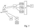
- FIG. 1 an information management system in which a position-code product and a sending device, such as a digital pen, can be integrated is shown.
- a position-code product and a sending device such as a digital pen
- the system of Fig. 1 includes a multitude of sending devices or digital pens DP and position code products P (only one of which being shown in Fig. 1), a look-up unit ALS, and a plurality of service handler units SH (only one of which is shown in Fig. 1).
- the information can be transmitted in any suitable way from the digital pen DP to the look-up unit ALS and the service handler unit SH.
- wireless transmission of information is effected from the digital pen DP to a network connection unit, which in turn transmits the information to the look-up unit ALS and service handler unit SH, respectively.
- the network connection unit can be an integral part of the digital pen DP.
- the network connection unit can be a mobile phone or a computer or any other suitable unit with an interface to a computer network such as the Internet or a LAN.
- the look-up unit ALS is connected to a virtual space database GSDB which includes data on the functionality of every position coded by the position code PC and the actor associated with each such position.
- the look-up unit ALS is also connected to a pen database PDB, which includes data on all digital pens in the system, such as the unique pen identifier of each pen and all settings or properties that are associated with each pen.
- the pen database PDB also includes data relating to the manufacturer of each pen.
- the look-up unit ALS is connected to an event database GEDB, which includes data on the transactions taking place in the look-up unit ALS, i.e. the address requests made by the pens in the system and the address responses returned to the pens, as well as any errors occurring in the process.
- GEDB event database
- the look-up unit ALS could be connected to one all-embracing database.
- the system also includes one or more networks in which network operators handle the communication between the digital pens DP and the look-up unit ALS, and between the digital pens DP and the service handler unit SH.
- This network operator could also act as a service handler in the system, for example by means of a server unit SP providing communication services that allows the pen owner to send electronic messages, for example e-mail, SMS or fax, based on information written on the position-coded products P by means of the digital pen DP.
- the server unit SP of the network operator could also provide for network storage of information generated in the system, for example entries in an position-coded calendar or notebook.
- the network operator maintains an application database ASDB which contains data on user-specific settings for different applications, for example a signature or electronic business card to be attached to e-mail messages, where and how to store sent messages, etc.
- the system includes Internet portals hosted by one or more web servers which are interfaced with the databases of the system, one portal of which P1 being shown in Fig. 1.
- the portal P1 is a so-called Partner Portal, i.e. a portal which allows pen manufactures, paper manufactures, service handlers and network operators to access selected portions of the databases of the system, via an interface unit IF.
- An example of another portal is a so-called Pen Owner Portal, i.e. a portal which allows for the pen owners to access selected portions of the databases of the system.
- the functionalities of the two portals are merged into one common portal.
- the information is sent in a secure way, i.e. by using encryption and digital signatures. If the digital pen DP sends confidential information to the service handler unit SH, the digital pen DP encrypts the information and the service handler unit SH will, in order to decipher the information, decrypt it.
- the digital pen DP can use either symmetric encryption or asymmetric encryption.
- a portion of a product such as the position-coded product used in the system of Fig. 1, in the form of a paper 1, provided with, on its surface 2, an optical readable position code pattern 3 which enables a determination of the position.
- the position code pattern includes markings 4, which are methodically arranged over the surface 2.
- the Applicant proposes in the international patent application WO 01/16691, which is incorporated herein by reference, the use of a product having a writing surface which is provided with such a position code.
- the position code which codes a plurality of positions on the surface, enables electronic recording of information that is being written on the writing surface, by means of a digital pen which detects the position code.
- the position code is capable of coding coordinates of a large number of positions, much larger than the number of required positions on the product.
- the position code can be seen as forming a virtual space which is defined by all positions that the position code is capable of coding, whereby different positions in the virtual space can be dedicated for different functions and/or actors. It should be noted that the position code pattern shown in Fig. 2 is, for the sake of clarity, greatly enlarged.
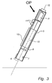
- Fig. 3 shows a schematic representation of an embodiment of a sending device designed for reading, for example, a position code pattern of Fig. 2.
- the device is a digital pen.
- the pen DP comprises a housing 5, shaped in a pen-like form.
- An opening 6 is provided at one end portion of the housing 5. The opening is intended to rest against, or to be held at a short distance from, the surface S from which information is to be obtained.
- a pressure sensor unit may also be comprised within the housing 5, which will be discussed below.
- the optical unit comprises a diode 7, arranged to illuminate the surface provided with the position code, and a light-sensitive sensor 8, for example a CCD sensor (Charge-Coupled Device) or a CMOS sensor (Complementary Metal-Oxide semiconductor), arranged to register two-dimensional images.
- the current supply unit is in this embodiment a battery 9, arranged in a separate container.
- the electronic unit 10 comprises a processor device including image-processing means, encryption means and a processor programmed to read images from the sensor 8 and to perform determination of the position and decoding of information on the basis of the images. Furthermore, the processor is programmed to perform computations in order to, for example from an image received from the sensor, calculate properties of the optical data obtained from the image. The data resulting from these computations can be used as input data for other computations or algorithms, such as encryption algorithms. In this embodiment, the AES and RSA algorithms are implemented in the processor device.
- the electronic unit 10 comprises a memory or data storage that is arranged, for example, to store data received from the processor or the sensor, as well as program instructions for the processor device.
- the pen may comprise a keypad 11, which enables activation and controlling of the pen.
- a transceiver 12 for wireless communication, by means of IR-light or radio waves, with other participants of the system of Fig. 1 is also included.
- a display 13 for showing, for example, registered information can be included.
- the keypad, the transceiver, and the display are in communication with and controlled by the electronic unit 10.
- FIG. 3 is schematical and that the actual configuration of the parts comprised within the pen may differ from the configuration shown without departing from the scope of the present invention.
- the position-code pattern is an optical readable pattern and, thus, the sensor is an optical sensor.
- the position code pattern can be based on another parameter than an optical parameter as mentioned above. In that case, the sensor must, of course, be of such a type that is capable of reading the parameter in question.
- the combination of a digital pen and a position-coded product can be used as an input device to a computer, a PDA, a mobile phone, or the like.
- text and sketches written on a position-coded notepad can be transferred via the pen to a computer.
- the combination of a pen and a position-coded product allows for global communication, directly from the product via the pen, by the position code on the product being dedicated for such communication.
- the information registered by the pen can be transformed into a fax message, an e-mail or an SMS, and can then be sent from the pen to a recipient.
- the combination of a pen and a position-coded product can be used in e-commerce.
- the digital pen can be used to order an item from a position-coded advertisement in a magazine, by the position code in the advertisement being dedicated for such a service.
- a patterned surface is read or scanned by the sensor 8, whereby an optical image OI is obtained.
- the image OI is then stored as a mapping of the pattern in an image storing medium.
- the optical image OI or the optical data representing the image includes a predetermined number of pixels.
- Each optical image OI is, in turn, divided into a predetermined number of subimages or image elements, wherein each image element includes a predetermined number of pixels.
- the size and number of these pixel representations, i.e. the resolution, is adjustable.
- each optical image includes 96x96 pixels. Furthermore, the 96x96 pixels are divided in a matrix constituent of 16x16 image elements, wherein each image element consequently consists of 6x6 pixels.
- each image element consequently consists of 6x6 pixels.
- the resulting optical data OD comprise information of the brightness on the portion of the surface that has been read. Factors having an influence on the sensed brightness have already been discussed above.
- the brightness is represented by discrete values.
- a white surface corresponds to a value of 255 and a black surface, e.g. a black marking, corresponds to a value of 0.
- each image element, representing a portion of the surface includes data of at least one marking and at least a portion of a surface surrounding the markings.
- any of the input values from the digital pen's sensors can be used as parameters for key generation. These parameters are then used in combination with the optical data OD or in combination with computer random seeds.
- the optical data OD produced by the sensor are processed to calculate specific statistical properties of the optical data.
- a maximum value, a minimum value and a sum value of the intensity or brightness of a number of pixels are calculated and used in the continued process as optical data.
- the thus calculated statistical values are hereinafter referred to as processed optical data POD. This calculation is performed on each image element, i.e. on the optical data OD represented in each image element, respectively.
- Other preferably statistical properties that may be calculated such as a mean value, or a standard deviation value.
- each image element is represented by one data record DR and each data record DR consists of four data fields.
- the first two data fields contain the calculated sum value, the third contains the calculated minimum value, and the fourth contains the calculated maximum value.
- a sequence of data records DR is produced from one optical image, each data record corresponding to one image element of the image.
- the data records DR are produced, they are optionally stored in a cyclic register, prior to the use as random number data, and are arranged in the processor device to be accessed by the processor when required, for example at the transmission of a message.
- the sequence of data records DR is processed in an algorithm in order to increase the stochasticity of the processed optical data in the data records.
- the processed optical data POD are not one hundred percent random in a statistical sense.
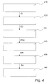
- Figs 5 and 8 show two different algorithms of two alternative embodiments of the present invention for increasing the randomness of the processed optical data. These algorithms will be described in greater detail below.
- the processed optical data are used as an encryption key EK in an encryption algorithm and encryption of a message obtained from the position-coded surface using the digital pen is performed.
- the processed optical data is, at step 460, used for authentication of a sent message. Then, the processed optical data are used as random number data, which is encrypted by means of an encryption key, for example a private key of the digital pen, and the encrypted random number data is used for authentication of said sent message.
- an encryption key for example a private key of the digital pen
- Encryption algorithms such as the AES encryption algorithm, uses block encryption.
- a block cipher i.e. an encryption algorithm using block encryption, is a method of encryption text (to produce ciphertext) in which an encryption key and algorithm are applied to a block of data at once as a group rather than to one bit at a time.
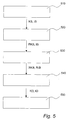
- Fig. 5 there is shown a flow diagram of the method according to a first preferred algorithm in accordance with the present invention for increasing the randomness or stochasticity of the processed optical data and to produce random numbers. It should be noted that the following description with reference to Figs 5, 6, 7A, and 7B corresponds to step 450 of Fig. 4.
- the sequence of data records is organized into data blocks, wherein each data block is determined or labeled as either a key data block KB or an input data block IB, in accordance with the description above.
- each data block is determined or labeled as either a key data block KB or an input data block IB, in accordance with the description above.
- four subsequent data records are organized in a single data block.
- every second data block is a key data block KB
- the intermediate data blocks are input data blocks IB.
- the key data blocks KB are processed according to a first mathematical algorithm
- the input data blocks IB are processed according to a second mathematical algorithm.
- the mathematical algorithms define a cyclic reordering or shifting procedure of the data fields included in the key data block KB and the input data block IB, respectively.
- Fig. 6 the order of the data fields within a key data block KB or an input data block IB are shown prior to the shifting procedure.
- the records are shown schematically as boxes divided into four elements, each element representing a data field.
- the fields indicated with 1 and 2 include the sum of brightness, the fields indicated with 3 the minimum, and the field indicated with 4 the maximum.
- the cyclic shifting scheme of the data fields included in the key data block KB is shown below in table 1. Table 1 Data record Steps A 0 B 3 C 2 D 1
- Fig. 7A the order of the data fields within the key data block after the cyclic shifting has been performed is shown.
- the data fields of the first data record, record A retain their positions
- the data fields within the second record, record B are shifted three positions to the right
- the fields within the third record, record C are shifted two positions to the right
- the fields within the fourth record, record D are shifted one position to the right.
- the data block output as a result of the reordering algorithm for a key data block is referred to as reordered key data block, RKB.
- Table 2 the cyclic shifting scheme of the data fields included in the input data block IB is shown.
- Table 2 Data record Steps A 1 B 2 C 3 D 0
- Fig. 7B there is shown the order of the data fields within the input data block after the cyclic shifting, to the right, has been performed.
- the data fields within the first data record, record A are shifted one position
- the data fields within the second data record, record B are shifted two positions
- the data fields within the third data record, record C are shifted three positions
- the data fields within the fourth data record, record D retain their positions.
- the data block output as a result of the reordering algorithm for an input data block is referred to as reordered input data block, RIB.
- step 540 the data in the thus reordered key and input data blocks are used as the encryption key, key data KD, and the initiation vector, input data ID, respectively, for the encryption algorithm.
- step 550 the method is returned to the procedure shown in Fig. 4 at step 460, where the actual encryption of the message is performed using, in this preferred embodiment, the AES encryption algorithm.
- the AES encryption algorithm is of course contemplated within the scope of the present invention.
- the algorithm can be regarded as having two parts.
- the seed update a random seed is calculated based on the processed optical data.
- the random number calculation the thus calculated random seed is used as input data for calculation of the random numbers to be used in the encryption algorithm.
- Data blocks that include a subset of the sequence of data records containing the processed optical data form the input data in the seed update part.
- the data records comprise data fields, preferably organized as is described above in relation to the first preferred embodiment.
- each data record includes four data fields, the first two including the sum value, the third the minimum value, and the fourth the maximum value, see Fig. 6.
- each data block is processed in a first hash function, which in this embodiment is an encryption algorithm, in order to increase the randomness of the data records containing the processed optical data.
- the first hash function is, in this embodiment, a symmetrical encryption algorithm.
- the data records containing the processed optical data are used as the encryption key, and an arbitrarily chosen vector is used as the initiation vector. However, it is preferred that the number of ones and zeros are substantially equal and appropriately distributed throughout the initiation vector. This can be achieved by using the previous seed as the initiation vector for the hashing algorithm, which will remove the risk of patterns that may be produced due to frequent seed updates with substantially similar input data, and will improve the quality of the random seed.
- an iterative process concatenates each hashing output or hash value, HV, and thereby forms hashing output data blocks. This is due to the fact that a hashing process normally results in an output having a data size that is less, or much less, than the data size of the input data. The number of iterations is dependent on the desired size of the output data.
- the output data blocks are then divided into key data blocks and seed data blocks at step 830.
- SI x Hash n (SI x , SU x )
- Y/n Y is the bit-length of the random number to be generated in the second step
- n is the bit-length of the output data of the hashing algorithm
- SU x is input data block x
- SI x is output data block x
- SK x is key data block x
- SD x seed data block x is SD x seed data block x.
- the hashing algorithm is performed using a symmetric encryption algorithm, AES.
- AES symmetric encryption algorithm
- the seed update can be performed with a full update of the seed, i.e. with all data blocks included in SI, or with one data block, SI x . This is dependent on the requirements of the random number calculation algorithm in part two and the computer power at hand.
- the key data blocks and seed data blocks are used as input data in a second algorithm, which in this embodiment utilizes a symmetrical encryption algorithm, for example AES.
- the algorithm performed at step 840 is an iterative algorithm.
- AES symmetrical encryption algorithm
- A3 or A5 which are stream ciphers and are used for symmetrical encryption, may be used.
- a counter, seed count is also included. It counts the number of times the random number calculation was used since the input data were updated in the seed update.
- steps 1.2 and 1.3 could be made in a number of other ways, but the described method ensures that all changes in a block is transformed through out most of the random seed, and thereby ensures a high quality random seed for the following calculation.
- the second algorithm is a hash function, preferably using the same symmetrical encryption algorithm as in the second algorithm described above.
- step 850 the method is returned to the procedure shown in Fig. 4 at step 460, where the actual encryption of the message is performed using, in this preferred embodiment, the AES encryption algorithm, where the random number data PR x obtained through the above method are used as the encryption key at step 460 of Fig. 4.
- an encryption of the random number data PR x is performed, for example by the use of an asymmetric encryption algorithm. Then, the encrypted random number data is sent to the receiver of the encrypted message. The receiver performs a hashing on the encrypted random number data and uses the resulting hash value as a private encryption key, which then is used in an asymmetric encryption algorithm for decryption of the received message.
Landscapes
- Engineering & Computer Science (AREA)
- Computer Security & Cryptography (AREA)
- Computer Networks & Wireless Communication (AREA)
- Signal Processing (AREA)
- General Physics & Mathematics (AREA)
- Theoretical Computer Science (AREA)
- Physics & Mathematics (AREA)
- Pure & Applied Mathematics (AREA)
- Life Sciences & Earth Sciences (AREA)
- Mathematical Optimization (AREA)
- Computational Mathematics (AREA)
- General Engineering & Computer Science (AREA)
- Power Engineering (AREA)
- Health & Medical Sciences (AREA)
- Mathematical Analysis (AREA)
- Biodiversity & Conservation Biology (AREA)
- Biomedical Technology (AREA)
- General Health & Medical Sciences (AREA)
- Mobile Radio Communication Systems (AREA)
- Storage Device Security (AREA)
- Communication Control (AREA)
- Two-Way Televisions, Distribution Of Moving Picture Or The Like (AREA)
- Radar Systems Or Details Thereof (AREA)
Abstract
Description
- The present invention generally relates to the field of transmitting information from a sender to a receiver. More specifically, the present invention relates to a method and a device for encrypting a message for secure transmission of such a message from a sending device to a receiver. The invention further relates to a computer readable medium comprising instructions for bringing a computer to perform such a method, and a sending device and a system, respectively, comprising such a device.
- During transmission of information from a sender to a receiver, for example in a system including hand-held devices, there are basically four aspects that need to be fulfilled for obtaining a secure transmission with regards to authenticity, integrity, confidentiality and non-repudiation. However, confidentiality, i.e. that the information is kept secret during the transmission, is crucial in the field of digital communication, for example in financial transactions or in e-commerce. This aspect, as well as the other aspects, can be met by using cryptography.
- When using cryptography or a network security algorithm based on cryptography, random number data is used for different reasons and play an essential role. For example, random numbers are frequently used as encryption keys or for generation of encryption keys. Furthermore, random data is by definition difficult to determine or guess.
- Common methods of cryptography include symmetric encryption and asymmetric encryption. When using symmetric encryption, the same key is used for both encryption and decryption. The encryption key is used in conjunction with an encryption algorithm, and different keys will result in different outputs from the algorithm. The degree of security of the encrypted message depends on the secrecy of the key and therefore on the random number used as the key or for generating the key, not on the secrecy of the algorithm. This makes it possible to use powerful standard algorithms, such as AES (Advanced Encryption Standard), DES (Data Encryption Standard) or IDEA (International Data Encryption Standard). The degree of security also depends on the length or bit size of the key. The longer the encryption key, the more difficult it is to break the cipher.
- When using asymmetric encryption, the sender and the receiver each has a private encryption key and a public encryption key. Thereby, confidentiality, authentication and non-repudiation is achieved. Commonly used asymmetric encryption algorithms include, for example, RSA (Rhivest-Shamir-Adleman) and DH (Diffie-Hellman).
- It is a well-known problem that sources for true random numbers are difficult to find. Physical noise generators, such as pulse detectors of ionizing radiation events, gas discharge tubes, and leaky capacitors, are one potential source. However, such devices are of limited utility in network security applications. For example, incorporating one of these devices into a hand-held device will require a complex and possibly bulky design of the hand-held device. Furthermore, there are problems both with the degree of randomness and the precision of numbers generated by such devices.
- Another approach for obtaining random numbers for cryptographic applications is to use algorithmic techniques. However, these algorithms are deterministic and therefore produce sequences of numbers that are not statistically random. Such numbers are often referred to as pseudo random numbers.
- A widely used technique for pseudo random number generation is the linear congruential method. A sequence of numbers is obtained via the following equation

- One problem with the above-mentioned method is that once a value, the random seed, has been chosen, the subsequent numbers in the sequence follow deterministically. This means that someone having knowledge of a part of the sequence could theoretically determine subsequent elements of the sequence.
- It is possible to implement more advanced random number generators that use the internal clock as random seed, for example such as the algorithm used in Blue-tooth. This and similar algorithms are able to generate pseudo random numbers with improved statistical characteristics compared to the numbers generated by the linear congruential method. However, the pseudo random numbers are still of an insufficient quality in a statistical sense, i.e. when considering the degree of randomness.
- The article "Stream cipher based on pseudorandom number generation with optical affine transformation", by Sasaki et al, published in Applied Optics, Vol. 39, No. 14, pp 2340-2346, on 10 May 2000, describes a technique for generating an image with pseudorandom intensity distribution by optical processing. Specifically, optical feedback processing is used by displaying an initial image on a CRT (Cathode Ray Tube). The CRT image is then imaged onto a CCD camera, via optical components that split, rotate, reflect, translate and recombine the image, whereupon the processed image is displayed on the CRT. The same procedure is then repeated for a large number of iterations. The final output image is used to encrypt an image message by optical modulo-n addition of the final output image to the image message. Apart from its evident inability of being readily implemented in a hand-held device, the known optical technique appears to suffer from both limited precision and slow processing speed.
- Thus, there remains a problem in finding a method, that can be implemented in a system comprising hand-held devices, that provide random numbers of good quality, according to the above-mentioned criterions, for generation of encryption keys for use in encryption algorithms in order to provide a secure transmission of information between a sender and a receiver.
- An example of a hand-held device is shown in US-A-5 852 434, which relates to an absolute position determination device for indicating the instantaneous position and movement of a stylus on a surface formatted with a position-related code for indicating X-Y coordinates.
- Thus, an object of the present invention is to provide an improved method and device for generating an encryption key and encrypting a message.
- This and other objects are achieved according to the present invention by providing a method for encryption according to
claim 1, a digital pen according to claim 20, and a method for authentication according to claim 36. Preferred embodiments are defined in the dependent claims. - Thus, the present invention is based on the advantageous insight of using optical data as random seed for generation of an encryption key, which in turn is used in an encryption algorithm for encrypting a message. The optical data obtained in accordance with the method of the present invention presents the requisite degree of randomness and unpredictability. In fact, the optical data can be considered as being "truly" random. Consequently, the degree of randomness is higher and the optical data used are more unpredictable as compared to the data used for random seed in the known methods described above. Thus, an improved degree of secrecy of the generated encryption key will be achieved.
- Traditionally, two distinct and not necessarily compatible criteria are used to determine the quality of a sequence of random numbers, unpredictability and randomness. In a "true" random sequence, each number is statistically independent of any other number in the sequence and is therefore unpredictable. Two criteria are used to validate the randomness of a sequence of numbers. First, uniform distribution of random numbers, which means that the frequency of occurrence of each of the numbers should be approximately the same. Second, independence between random numbers, which means that no value in the sequence can be inferred from any of the others.
- According to the preferred embodiment of the present invention, a surface, or a portion thereof, is scanned or read with an optical sensor, preferably a camera or a light-sensitive sensor, thereby obtaining optical data representative of characteristics the read surface. The light-sensitive sensor being, for example, a CCD sensor (Charge-Coupled Device) or a CMOS sensor (Complementary Metal-Oxide semiconductor). The obtained optical data are determined by and represent values of at least one optical parameter, which is representative of physical conditions on the portion of the surface.
- Preferably, the optical data are obtained from a portion of a surface provided with a position code pattern, wherein the position code pattern includes optical readable markings. Each of said markings may be designed more or less arbitrarily. However, the design of each marking is preferably elementary, for example in the shape of round dots as shown in the detailed description below. The position code pattern is implemented using any parameter, which may be used to achieve symbols of the above-mentioned type that may be detected or sensed by an optical detector or optical sensor. The fact that the position code pattern is optically readable facilitates the appliance of the pattern onto the surface. Accordingly, the pattern should have the capability to reflect light, which not necessarily has to have a wavelength in the visible spectrum.
- Preferably, the parameter sensed and used for the generation of the encryption key is brightness, which is a relative measure of the intensity of the energy output of a light source that is visible for an optical sensor. In the preferred embodiment of the present invention, the brightness of light that is reflected from a portion of an illuminated surface is registered. Of course, the sensed light does not necessarily have to constitute reflected light. Sensing of emitted light from luminous surfaces are also contemplated within the scope of the present invention, or any combinations of emitted and reflected light. The brightness in the sensed light may, for example, depend on variations in the surrounding illumination, the quality of the printing of the pattern, the blacking of the markings, and/or the quality of the surface, e.g. a paper surface. Biometric factors may also have an impact on the brightness, for example the inclination of the pen. These and other factors introduce a considerable degree of randomness in the optical data. Furthermore, the fact that the optical sensor in itself is a noise generator will even further enhance the degree of randomness in the optical data.
- According to preferred embodiments of the invention, the optical data are processed according to a preprogrammed order or scheme and organized in data fields of a predetermined length. The data fields, in turn, are preferably organized in data records according to a predetermined scheme, e.g. in a predetermined order.
- According to a specific preferred embodiment of the present invention, and in order to even further improve the stochasticity of the optical data organized in said data records, the order of the data fields within the data records are rearranged according to a cyclic reordering algorithm. According to the cyclic reordering algorithm, the order of the rearranged data fields in different data records may differ from one data record to another. Thus, a number of different reordering schemes may be used, including the case that for some data records, the order of the data fields is not altered at all. Preferably, the cyclic reordering is performed by shifting all data fields in each data record. The data fields may be shifted by a number of steps ranging from zero, i.e. no shift takes place, to a number corresponding to the number of data fields in the
data record minus 1. Thus, the reordering algorithm contains information as to the number of steps each data field is shifted for a specific data record. - According to a specific embodiment of the present invention, the order of the data fields in each record included in a first set of data records are rearranged according to a first reordering algorithm. Thereby, a first set of rearranged data records is obtained. Then, the order of the data fields in each data record of a second set of data records are rearranged according to a second reordering algorithm, whereby a second set of rearranged data records is obtained. In the generation of the encryption key, the first set of rearranged data records forms key data and the second set of rearranged data records forms input data, or vice versa, of the encryption key used in the encryption algorithm. Alternatively, the key data and the input data form encryption data that can be used as material in an encryption process. For example, the material can be encrypted with the public key of the receiver, to be used as encryption key or key material, to be compressed to an encryption key, for a symmetric encryption algorithm. The advantage of the described rearranging process is that the statistical characteristics, i.e. the randomness and unpredictability, of the processed data are significantly improved.
- According to a further preferred embodiment of the invention, it has surprisingly been found that a particular high degree of stochasticity have been achieved using the specific reordering algorithm explained in greater detail below. In fact, the output data of the encryption algorithm, when using the optical data as random seed and the described reordering algorithm, constitute uniformly distributed noise according to prevalent statistical testing methods.
- According to an alternative preferred embodiment of the invention, the stochasticity of the obtained optical data organized in data records is improved using hash functions. According to this embodiment, a first hashing is performed on a set of a predetermined number of data records by a first algorithm, i.e. a first hash function. As understood by the person skilled in the art, hashing is an iterative process which will not be described in detail. Therefore, the term hashing output, as used hereinafter, refers to the result of all iterations included in the hashing. Thus, a first output, i.e. a first hashing output, is obtained from the first hashing. The first output is then used as an input to a second algorithm, which may be a second hash function. The output of the second algorithm, i.e. random numbers, is then, for example, used as the encryption key or for generating an encryption key in an encryption algorithm for encrypting a message. However, the second algorithm may alternatively be an iterative algorithm different from a hash function. For example, A3 or A5, which are stream ciphers and are used for symmetrical encryption, may be used.
- The first hash function introduces distortion or noise in the obtained optical data used as input data. In other words, it shatter the regularities in the optical data and the correlation between data fields included in the data records. The use of a second hash function, or an alternative, preferably iterative, algorithm, on the first output further improves the statistical characteristics of the data and provides a further distortion on the first output. Thus, the statistical characteristics, i.e. the randomness and unpredictability, of the processed optical data are significantly improved using the method according to this embodiment. The improvement is such that the random numbers generated as a result of the method of this embodiment can be regarded as uniformly distributed white noise according to prevalent statistical testing methods. According to a preferred alternative of this embodiment, symmetrical encryption algorithms are used in the first and second algorithms. By using the same encryption algorithm for the algorithms, the advantages of a simplified implementation of the program code of the algorithms and a saving of memory capacity are achieved.
- Furthermore, when using a symmetrical encryption algorithm, such as AES, for the actual encryption of the message, this encryption algorithm is preferably used in at least one of said algorithms as well, and preferably in both. However, it is conceivable within the scope of the present invention that other and different encryption algorithms may be used in each of said algorithms, as well as for the actual encryption of the message. Preferably, in order to even further improve the stochasticity of the encryption key, or of the random numbers used for generating the encryption key, statistical properties of the parameter are. This results in a higher degree of randomness and unpredictability. Examples of statistical properties preferably being used includes maximum, minimum and sum values of the sensed parameter. However, other statistical properties are conceivable, such as mean values, standard deviation values, etc. As realized by the person skilled in the art, the use of said calculation of statistical properties is by no means restricted to a specific embodiment of the present invention. Contrarily, the statistical properties of the optical data may be calculated and the result thereof may be used to improve the stochasticity of the optical data, and the encryption key generated therewith, regardless of the chosen method for generating the encryption key.
- Furthermore, the optical data used for generating an encryption key may constitute part of the message to be encrypted and transmitted. Alternatively, the optical data do not constitute part of the message. Furthermore, the step of obtaining optical data for encrypting the message may be obtained prior to, during, or following the procedure of obtaining the message to be encrypted. As an example, the encryption of the message may take place just prior to the actual transmission thereof. Then, the encryption key, including obtaining optical data, whether the optical data are extracted from the message or not, may be generated in connection with the encryption procedure. Alternatively, the generation of the encryption key may have been performed earlier, e.g. in connection with obtaining and storing the message, and a stored encryption key is used for the encryption.
- Suitably, the optical data used for generating an encryption key are stored in a storage medium prior to processing thereof. In an alternative embodiment the optical data are stored after the processing thereof.
- Preferably, a symmetrical encryption algorithm is used for the actual encryption of the message. There are a number of conceivable symmetrical encryption algorithms that are suitable, for example AES, DES, or IDEA. The use of an asymmetric encryption algorithm, such as the RSA, for the actual encryption of the message is also conceivable and lie within the scope of the present invention. However, the present invention is not limited to a specific encryption algorithm.
- The method of the present invention is implemented in a digital pen. Such a digital pen comprises an optical sensor for obtaining a message to be transmitted, for instance from a surface provided with a position code pattern as described above. Preferably, the digital pen also comprises illumination means for illuminating a surface to be read by the optical sensor. The illumination means and the optical sensor may be restricted to a limited wavelength range, such that the optical sensor primarily detects reflected light that are provided by the illumination means. The optical sensor is also used for obtaining the optical data used for generating an encryption key. Thereby, no additional sensor or random number generator is required within the limited interior of the digital pen.
- Furthermore, the digital pen comprises a processor or processing means for performing the steps of the present invention, as well as all the steps required for obtaining, encrypting and transmitting a message. Furthermore, the digital pen also comprises, inter alia, suitable storing means for storing data, power supply means, e.g. a battery, as well as transmission means for transmitting the message to a receiver.
- According to a further embodiment of the invention, a pressure sensor is provided for obtaining pressure data. Since the pressure data relates to biometric factors, such as movements of the hand, the degree of randomness of the pressure data is high. The pressure data can then be used in combination with the optical data as random number data or random seed, in the generation of an encryption key, in order to enhance the degree of randomness in the random seed.
- Also, according to yet another embodiment of the invention, time data are obtained and used in combination with the optical data as random seed in order to enhance the stochasticity of the random seed. Although time data is deterministic by nature, the degree of randomness of the combined data will not be decreased. The time data are preferably provided by the internal clock of the processing means. The thus obtained random seed may be subsequently used in the generation of the encryption key in the manner as described above.
- As understood be the person skilled in the art, there are other related areas where the random numbers generated from optical data in accordance with the present invention may be utilized. One such area is authentication of a sent or received message.
- Another area is key transport from a sender to a receiver. Then, the random numbers are encrypted with a public key of the receiver and are used as an encryption key or key data, to be subsequently compressed to an encryption key, for a symmetric encryption algorithm.
- The random numbers can also be used to generate prime numbers for RSA or DH keys.
- As realized by the person skilled in the art, the method and the device of the present invention, as well as the preferred embodiments thereof, are suitable to realize as a computer program or a computer readable medium, preferably within the contents of a digital pen.
- Further objects and advantages of the present invention will be discussed below by means of exemplifying embodiments.
- Preferred embodiments of the invention will now be described in greater detail with reference to the accompanying drawings, in which
- Fig. 1 shows an embodiment of an information management system;
- Fig. 2 schematically shows an embodiment of a product provided with a position-code pattern;
- Fig. 3 schematically shows an embodiment of a sending device according to the present invention;
- Fig. 4 shows a flow diagram illustrating an embodiment of a method according to the present invention for encrypting a message using optical data;
- Fig. 5 shows a flow diagram illustrating an algorithm of a first embodiment for increasing randomness in optical data used for generating an encryption key;
- Fig. 6 schematically shows the order of data fields within a key data block and an input data block prior to a cyclic reordering procedure according to an embodiment of the present invention;
- Figs 7A and 7B schematically show the order of data fields within the key data block and input data block, respectively, after said cyclic reordering procedure; and
- Fig. 8 shows a flow diagram illustrating an algorithm of a second embodiment for increasing the randomness in the input data used for generating an encryption key.
- In the following, an information management system in which the present invention can be implemented is described with reference to Fig. 1. After this general presentation of the system structure, a product provided with a position code pattern will be described with reference to Fig. 2. Then, with reference to Fig. 3, a sending device, in which the present inventive method and device can be implemented, designed for reading and obtaining optical data from the position code of Fig. 2 is shown.
- With reference first to Fig. 1, an information management system in which a position-code product and a sending device, such as a digital pen, can be integrated is shown. There are many inter-reliant actors involved in the system of Fig. 1: companies manufacturing the digital pens ("pen manufactures"), companies manufacturing the position-coded products ("paper manufactures"), companies providing different services by means of service handler units ("service handlers"), a company administrating the position-code based on the virtual space database ("pattern administrator"), operators providing the communication links between the digital pens and the different units ("network operators"), and a multitude of users of digital pens ("pen owners").
- The system of Fig. 1 includes a multitude of sending devices or digital pens DP and position code products P (only one of which being shown in Fig. 1), a look-up unit ALS, and a plurality of service handler units SH (only one of which is shown in Fig. 1). It should be noted that the information can be transmitted in any suitable way from the digital pen DP to the look-up unit ALS and the service handler unit SH. In one embodiment, wireless transmission of information is effected from the digital pen DP to a network connection unit, which in turn transmits the information to the look-up unit ALS and service handler unit SH, respectively. The network connection unit can be an integral part of the digital pen DP. Alternatively, the network connection unit can be a mobile phone or a computer or any other suitable unit with an interface to a computer network such as the Internet or a LAN. The look-up unit ALS is connected to a virtual space database GSDB which includes data on the functionality of every position coded by the position code PC and the actor associated with each such position. The look-up unit ALS is also connected to a pen database PDB, which includes data on all digital pens in the system, such as the unique pen identifier of each pen and all settings or properties that are associated with each pen. The pen database PDB also includes data relating to the manufacturer of each pen. In addition thereto, the look-up unit ALS is connected to an event database GEDB, which includes data on the transactions taking place in the look-up unit ALS, i.e. the address requests made by the pens in the system and the address responses returned to the pens, as well as any errors occurring in the process. As an alternative to individual databases as shown in Fig. 1, the look-up unit ALS could be connected to one all-embracing database.
- The system also includes one or more networks in which network operators handle the communication between the digital pens DP and the look-up unit ALS, and between the digital pens DP and the service handler unit SH. To this end, the owner of a pen has opened a subscription at one of the network operators. This network operator could also act as a service handler in the system, for example by means of a server unit SP providing communication services that allows the pen owner to send electronic messages, for example e-mail, SMS or fax, based on information written on the position-coded products P by means of the digital pen DP. The server unit SP of the network operator could also provide for network storage of information generated in the system, for example entries in an position-coded calendar or notebook. When acting as a service handler, the network operator maintains an application database ASDB which contains data on user-specific settings for different applications, for example a signature or electronic business card to be attached to e-mail messages, where and how to store sent messages, etc.
- In the embodiment of Fig. 1, the system includes Internet portals hosted by one or more web servers which are interfaced with the databases of the system, one portal of which P1 being shown in Fig. 1. The portal P1 is a so-called Partner Portal, i.e. a portal which allows pen manufactures, paper manufactures, service handlers and network operators to access selected portions of the databases of the system, via an interface unit IF. An example of another portal is a so-called Pen Owner Portal, i.e. a portal which allows for the pen owners to access selected portions of the databases of the system. In an alternative embodiment, the functionalities of the two portals are merged into one common portal.
- In the communication between the different participants illustrated in Fig. 1, it is desirable that the information is sent in a secure way, i.e. by using encryption and digital signatures. If the digital pen DP sends confidential information to the service handler unit SH, the digital pen DP encrypts the information and the service handler unit SH will, in order to decipher the information, decrypt it. The digital pen DP can use either symmetric encryption or asymmetric encryption.
- In Fig. 2, a portion of a product, such as the position-coded product used in the system of Fig. 1, in the form of a
paper 1, provided with, on itssurface 2, an optical readableposition code pattern 3 which enables a determination of the position. The position code pattern includesmarkings 4, which are methodically arranged over thesurface 2. The Applicant proposes in the international patent application WO 01/16691, which is incorporated herein by reference, the use of a product having a writing surface which is provided with such a position code. The position code, which codes a plurality of positions on the surface, enables electronic recording of information that is being written on the writing surface, by means of a digital pen which detects the position code. The position code is capable of coding coordinates of a large number of positions, much larger than the number of required positions on the product. Thus, the position code can be seen as forming a virtual space which is defined by all positions that the position code is capable of coding, whereby different positions in the virtual space can be dedicated for different functions and/or actors. It should be noted that the position code pattern shown in Fig. 2 is, for the sake of clarity, greatly enlarged. - Fig. 3 shows a schematic representation of an embodiment of a sending device designed for reading, for example, a position code pattern of Fig. 2. The device is a digital pen. The pen DP comprises a
housing 5, shaped in a pen-like form. Anopening 6 is provided at one end portion of thehousing 5. The opening is intended to rest against, or to be held at a short distance from, the surface S from which information is to be obtained. - Within the
housing 5 an optical unit, an electronic unit, and a current supply unit are incorporated. According to further embodiments of the digital pen, a pressure sensor unit may also be comprised within thehousing 5, which will be discussed below. - The optical unit comprises a diode 7, arranged to illuminate the surface provided with the position code, and a light-
sensitive sensor 8, for example a CCD sensor (Charge-Coupled Device) or a CMOS sensor (Complementary Metal-Oxide semiconductor), arranged to register two-dimensional images. The current supply unit is in this embodiment abattery 9, arranged in a separate container. - The
electronic unit 10 comprises a processor device including image-processing means, encryption means and a processor programmed to read images from thesensor 8 and to perform determination of the position and decoding of information on the basis of the images. Furthermore, the processor is programmed to perform computations in order to, for example from an image received from the sensor, calculate properties of the optical data obtained from the image. The data resulting from these computations can be used as input data for other computations or algorithms, such as encryption algorithms. In this embodiment, the AES and RSA algorithms are implemented in the processor device. - Also, the
electronic unit 10 comprises a memory or data storage that is arranged, for example, to store data received from the processor or the sensor, as well as program instructions for the processor device. - Furthermore, the pen may comprise a
keypad 11, which enables activation and controlling of the pen. Atransceiver 12 for wireless communication, by means of IR-light or radio waves, with other participants of the system of Fig. 1 is also included. Additionally, adisplay 13 for showing, for example, registered information can be included. The keypad, the transceiver, and the display are in communication with and controlled by theelectronic unit 10. - It should be noted that the illustration of Fig. 3 is schematical and that the actual configuration of the parts comprised within the pen may differ from the configuration shown without departing from the scope of the present invention.
- In the above-mentioned embodiment, the position-code pattern is an optical readable pattern and, thus, the sensor is an optical sensor. The position code pattern can be based on another parameter than an optical parameter as mentioned above. In that case, the sensor must, of course, be of such a type that is capable of reading the parameter in question.
- The combination of a digital pen and a position-coded product can be used as an input device to a computer, a PDA, a mobile phone, or the like.
- For example, text and sketches written on a position-coded notepad can be transferred via the pen to a computer. Additionally, the combination of a pen and a position-coded product allows for global communication, directly from the product via the pen, by the position code on the product being dedicated for such communication. For example, the information registered by the pen can be transformed into a fax message, an e-mail or an SMS, and can then be sent from the pen to a recipient. Further, the combination of a pen and a position-coded product can be used in e-commerce. For example, the digital pen can be used to order an item from a position-coded advertisement in a magazine, by the position code in the advertisement being dedicated for such a service.
- The above concept has been implemented in a system or infrastructure, which is shown in Fig. 1 and which is further disclosed in Applicant's international patent applications WO 0 148 678, WO 0 148 591 and WO 0 148 685.
- There will now be presented in the form of a flow diagram, with reference to Fig. 4, the inventive method for encryption of a message based on information written on the position coded products of Fig. 2 by means of the sending device of Fig. 3, and to thereby provide a secure transmission of said message from a sending device to a receiver, for example in the form of an e-mail, an SMS, or a fax. Furthermore, the position coded product and the sending device is preferably incorporated in a system as presented in Fig. 1.
- Beginning at
step 410, a patterned surface is read or scanned by thesensor 8, whereby an optical image OI is obtained. The image OI is then stored as a mapping of the pattern in an image storing medium. The optical image OI or the optical data representing the image includes a predetermined number of pixels. Each optical image OI is, in turn, divided into a predetermined number of subimages or image elements, wherein each image element includes a predetermined number of pixels. The size and number of these pixel representations, i.e. the resolution, is adjustable. - According to one exemplifying embodiment, each optical image includes 96x96 pixels. Furthermore, the 96x96 pixels are divided in a matrix constituent of 16x16 image elements, wherein each image element consequently consists of 6x6 pixels. Of course, there are any number of conceivable pixel configurations of an optical image that can be used without departing from the scope of the present invention.
- At
step 420, decoding of information comprised in the data of the optical image is performed. In the preferred embodiment, the resulting optical data OD comprise information of the brightness on the portion of the surface that has been read. Factors having an influence on the sensed brightness have already been discussed above. The brightness is represented by discrete values. In the preferred embodiment of the present invention, a white surface corresponds to a value of 255 and a black surface, e.g. a black marking, corresponds to a value of 0. To enhance the dynamics of the optical data, it is preferred that each image element, representing a portion of the surface, includes data of at least one marking and at least a portion of a surface surrounding the markings. - However, any of the input values from the digital pen's sensors, such as pen pressure, coordinates, time, or the like, can be used as parameters for key generation. These parameters are then used in combination with the optical data OD or in combination with computer random seeds.
- At
step 430, the optical data OD produced by the sensor are processed to calculate specific statistical properties of the optical data. According to the most preferred embodiments, a maximum value, a minimum value and a sum value of the intensity or brightness of a number of pixels are calculated and used in the continued process as optical data. The thus calculated statistical values are hereinafter referred to as processed optical data POD. This calculation is performed on each image element, i.e. on the optical data OD represented in each image element, respectively. There are, of course, other preferably statistical properties that may be calculated, such as a mean value, or a standard deviation value. - Thereafter, at
step 440, the resulting sequence of processed optical data POD is organized in bit-groups or data fields. According to the most preferred embodiment of the present invention, each image element is represented by one data record DR and each data record DR consists of four data fields. The first two data fields contain the calculated sum value, the third contains the calculated minimum value, and the fourth contains the calculated maximum value. Thus, a sequence of data records DR is produced from one optical image, each data record corresponding to one image element of the image. When the data records DR are produced, they are optionally stored in a cyclic register, prior to the use as random number data, and are arranged in the processor device to be accessed by the processor when required, for example at the transmission of a message. - Then, at
step 450, the sequence of data records DR is processed in an algorithm in order to increase the stochasticity of the processed optical data in the data records. This is due to the fact that the processed optical data POD are not one hundred percent random in a statistical sense. Thus, it is desirable to perform additional processing in order to improve the statistical characteristics of the optical data, i.e. increase the randomness or stochasticity of the processed optical data, before the processed optical data is used as a random seed. Figs 5 and 8 show two different algorithms of two alternative embodiments of the present invention for increasing the randomness of the processed optical data. These algorithms will be described in greater detail below. - Finally, at
step 460, the processed optical data are used as an encryption key EK in an encryption algorithm and encryption of a message obtained from the position-coded surface using the digital pen is performed. - According to an alternative embodiment, the processed optical data is, at
step 460, used for authentication of a sent message. Then, the processed optical data are used as random number data, which is encrypted by means of an encryption key, for example a private key of the digital pen, and the encrypted random number data is used for authentication of said sent message. - Encryption algorithms, such as the AES encryption algorithm, uses block encryption. A block cipher, i.e. an encryption algorithm using block encryption, is a method of encryption text (to produce ciphertext) in which an encryption key and algorithm are applied to a block of data at once as a group rather than to one bit at a time. The main alternative method, used much less frequently, is called the stream cipher.
- There is a cryptologic difficulty when the text to be encrypted contains static data, that do not change from on text to the other. If different encryption keys are used to encrypt the text that contains static data, an attacker could draw conclusions regarding the key if the position of the static data is known by the attacker. In order to prevent this, it is common to apply the cipher text from the previous encrypted block to the next block in the sequence. This way of encrypting in block ciphers are often referred to as CBC (Cipher Block Chaining) encryption. The encryption of the block including the static data is then dependent of all previous text blocks, which makes it more or less impossible to draw conclusions regarding the key from the encryption of the static data. To ensure this, an initiation vector derived from a random generator is combined with the text in the first block. Consequently, and according to preferred embodiments of the present invention, the processed optical data are used for forming both the encryption key, i.e. the key data block, and the initiation vector, i.e. the input data block.
- With reference now to Fig. 5, there is shown a flow diagram of the method according to a first preferred algorithm in accordance with the present invention for increasing the randomness or stochasticity of the processed optical data and to produce random numbers. It should be noted that the following description with reference to Figs 5, 6, 7A, and 7B corresponds to step 450 of Fig. 4.
- First, at
step 510, the sequence of data records, obtained atstep 440 of Fig. 4, is organized into data blocks, wherein each data block is determined or labeled as either a key data block KB or an input data block IB, in accordance with the description above. According to the most preferred embodiment of the present invention, four subsequent data records are organized in a single data block. Furthermore, every second data block is a key data block KB, and the intermediate data blocks are input data blocks IB. - Then, at
step 520, the key data blocks KB are processed according to a first mathematical algorithm, and atstep 530 the input data blocks IB are processed according to a second mathematical algorithm. The mathematical algorithms define a cyclic reordering or shifting procedure of the data fields included in the key data block KB and the input data block IB, respectively. - With particular reference to Fig. 6, the order of the data fields within a key data block KB or an input data block IB are shown prior to the shifting procedure. The records are shown schematically as boxes divided into four elements, each element representing a data field. In the most preferred embodiment, the fields indicated with 1 and 2 include the sum of brightness, the fields indicated with 3 the minimum, and the field indicated with 4 the maximum. The cyclic shifting scheme of the data fields included in the key data block KB is shown below in table 1.
Table 1 Data record Steps A 0 B 3 C 2 D 1 - In Fig. 7A, the order of the data fields within the key data block after the cyclic shifting has been performed is shown. The data fields of the first data record, record A, retain their positions, the data fields within the second record, record B, are shifted three positions to the right, the fields within the third record, record C, are shifted two positions to the right, and the fields within the fourth record, record D, are shifted one position to the right. The data block output as a result of the reordering algorithm for a key data block is referred to as reordered key data block, RKB.
- In table 2, the cyclic shifting scheme of the data fields included in the input data block IB is shown.
Table 2 Data record Steps A 1 B 2 C 3 D 0 - In Fig. 7B, there is shown the order of the data fields within the input data block after the cyclic shifting, to the right, has been performed. The data fields within the first data record, record A, are shifted one position, the data fields within the second data record, record B, are shifted two positions, the data fields within the third data record, record C, are shifted three positions, and the data fields within the fourth data record, record D, retain their positions. The data block output as a result of the reordering algorithm for an input data block is referred to as reordered input data block, RIB.
- It should be noted that a wide variety of shifting algorithms may be used within the scope of the present invention to obtain reordered or rearranged key and input data blocks. However, it has surprisingly been found that the above described reordering of the data fields within the data records included in the key data block and the input data block provides a particular and considerable improvement of the desired statistical properties for the output data of an ensuing encryption, when using the result of the reordering procedure as key data and input data for the encryption. In other words, the randomness and stochasticity of the output data is increased and the predictability is decreased. In fact, according to statistical testing procedures recognized within the art, the output data of the encryption algorithm, i.e. the encrypted message, can be regarded as uniformly distributed white noise. This unexpected effect is due to the fact that the correlation between the processed optical data included in the data fields within a data record, which in turn is transmitted to the output data of the encryption algorithm, is shattered by the above-mentioned reordering procedure.
- Then, at
step 540, the data in the thus reordered key and input data blocks are used as the encryption key, key data KD, and the initiation vector, input data ID, respectively, for the encryption algorithm. - Finally, at
step 550, the method is returned to the procedure shown in Fig. 4 atstep 460, where the actual encryption of the message is performed using, in this preferred embodiment, the AES encryption algorithm. However, other encryption algorithms are of course contemplated within the scope of the present invention. - Below, a second alternative preferred embodiment of an algorithm for improving the statistical characteristics of the processed optical data will be described, with particular reference to Fig. 8.
- The algorithm can be regarded as having two parts. In the first part, referred to as the seed update, a random seed is calculated based on the processed optical data. In the second part, referred to as the random number calculation, the thus calculated random seed is used as input data for calculation of the random numbers to be used in the encryption algorithm.
- Data blocks that include a subset of the sequence of data records containing the processed optical data form the input data in the seed update part. The data records comprise data fields, preferably organized as is described above in relation to the first preferred embodiment. Thus, each data record includes four data fields, the first two including the sum value, the third the minimum value, and the fourth the maximum value, see Fig. 6.
- At
step 810, each data block is processed in a first hash function, which in this embodiment is an encryption algorithm, in order to increase the randomness of the data records containing the processed optical data. The first hash function is, in this embodiment, a symmetrical encryption algorithm. The data records containing the processed optical data are used as the encryption key, and an arbitrarily chosen vector is used as the initiation vector. However, it is preferred that the number of ones and zeros are substantially equal and appropriately distributed throughout the initiation vector. This can be achieved by using the previous seed as the initiation vector for the hashing algorithm, which will remove the risk of patterns that may be produced due to frequent seed updates with substantially similar input data, and will improve the quality of the random seed. - Then, at
step 820, an iterative process concatenates each hashing output or hash value, HV, and thereby forms hashing output data blocks. This is due to the fact that a hashing process normally results in an output having a data size that is less, or much less, than the data size of the input data. The number of iterations is dependent on the desired size of the output data. - The output data blocks are then divided into key data blocks and seed data blocks at
step 830. The key data blocks and seed data blocks are used as input data in the random number calculation part. This can mathematically be written asInput data: optical data = SU2*m-1..SU1SU0 Calculation: SIx = Hashn (SIx, SUx) Output data: seed input = SI2*m-1..SI1SI0 = SKm-1..SK1SK0SDm-1..SD1SD0 key data = SKm-1..SK1SK0 seed data = SDm-1..SD1SD0 - Then, at
step 840, in the random number calculation part, the key data blocks and seed data blocks are used as input data in a second algorithm, which in this embodiment utilizes a symmetrical encryption algorithm, for example AES. The algorithm performed atstep 840 is an iterative algorithm. As mentioned above, there are a number of alternative encryption algorithms that can be used in said second algorithm instead of AES, for example IDEA or DES. Alternatively, A3 or A5, which are stream ciphers and are used for symmetrical encryption, may be used. A counter, seed count, is also included. It counts the number of times the random number calculation was used since the input data were updated in the seed update. Mathematically, the random number calculation can be written asInput data: key data = SKm-1..SK1SK0 seed data = SDm-1..SD1SD0 seed count Calculation For x from 0 to (m-1) 1.1 PRx = Encrypt (key=SKx, input=SDx) 1.2 SK(x+2)mod m = SK(x+2)mod m xor PRx 1.3 SD(x+1)mod m = SD(x+1)mod m xor PRx seed count = seed count + 1 Output data: random number = PRm-1..PR1PR0 key data = SKm-1..SK1SK0 seed data = SDm-1..SD1SD0 seed count - The transformation of steps 1.2 and 1.3 could be made in a number of other ways, but the described method ensures that all changes in a block is transformed through out most of the random seed, and thereby ensures a high quality random seed for the following calculation.
- According to an alternative embodiment, the second algorithm is a hash function, preferably using the same symmetrical encryption algorithm as in the second algorithm described above.
- Finally, at
step 850, the method is returned to the procedure shown in Fig. 4 atstep 460, where the actual encryption of the message is performed using, in this preferred embodiment, the AES encryption algorithm, where the random number data PRx obtained through the above method are used as the encryption key atstep 460 of Fig. 4. - Alternatively, an encryption of the random number data PRx is performed, for example by the use of an asymmetric encryption algorithm. Then, the encrypted random number data is sent to the receiver of the encrypted message. The receiver performs a hashing on the encrypted random number data and uses the resulting hash value as a private encryption key, which then is used in an asymmetric encryption algorithm for decryption of the received message.
- Although specific embodiments have been shown and described herein for purposes of illustration and exemplification, it is understood by those of ordinary skill in the art that the specific embodiments shown and described may be substituted for a wide variety of alternative and/or equivalent implementations without departing from the scope of the present invention. Those of ordinary skill in the art will readily appreciate that the present invention could be implemented in a wide variety of embodiments, including various hardware and software implementations, or combinations thereof. This application is intended to cover any adaptations or variations of the preferred embodiments discussed herein. Consequently, the present invention is defined by the wordings of the appended claims.
Claims (36)
- A method in a digital pen (DP) for encrypting a message for secure transmission of said message from the digital pen (DP) to a receiver (ALS, SH, SP), characterized by the steps of obtaining the message by registering images of a surface (2) provided with a position code pattern (3) using an optical sensor (8) in the digital pen (DP) and determining at least one position from the images;
obtaining (410-420) optical data for the generation of an encryption key using the optical sensor (8) in the digital pen (DP), said optical data electronically representing values of an optical parameter readable by said optical sensor (8);
generating (430-450), exclusively by electronic processing in a processor (10) of the digital pen, the encryption key using said optical data as random seed; and
encrypting (460) said message using said encryption key in an encryption algorithm. - The method according to claim 1, wherein said optical parameter is brightness sensed by said optical sensor (8).
- The method according to claim 1 or 2, wherein the step (410-420) of obtaining optical data comprises the step of
obtaining said optical data from a portion of a surface (2) provided with a position code pattern (3), wherein said position code pattern (3) includes optical readable markings (4), and wherein said optical parameter is representative of said portion. - The method according to any one of claims 1-3, wherein the step (430-450) of generating an encryption key comprises the steps of
processing (430) said optical data according to a predetermined scheme,
organizing (440) said processed optical data in data fields, wherein each data field has a predetermined size, and
organizing (440) said data fields in a predetermined order in data records. - The method according to claim 4, wherein the step (430) of processing said optical data comprises the step of
calculating statistical properties of sets of said optical parameter values represented by said optical data, whereby said statistical properties constitute said processed optical data. - The method according to claim 5, wherein said statistical properties comprise a maximum value, a minimum value and a sum value of said set of optical parameter values, and wherein the steps (440) of organizing comprises the steps of
organizing said maximum value in at least one maximum data field, said minimum value in at least one minimum data field, and said sum value in at least one sum data field, and
organizing said maximum, minimum, and sum data fields in a data record according to said predetermined order. - The method according to any one of claims 4-6, wherein the step (430-450) of generating an encryption key further comprises the steps of
rearranging (520) the order of said data fields within at least one data record of a first series of data records according to a first reordering algorithm, thereby obtaining a first series of rearranged data records, and
rearranging (530) the order of said data fields within at least one data record of a second series of data records according to a second reordering algorithm, thereby obtaining a second series of rearranged data records. - The method according to claim 7, wherein an encryption key comprises key data and input data, and wherein the step (430-450) of generating an encryption key comprises the steps of
using (540) said first series of rearranged data records as said key data, and
using (540) said second series of rearranged data records as said input data. - The method according to any one of claims 4-6, wherein the step (430-450) of generating an encryption key comprises the steps of
processing a set of a predetermined number of said data records in a first step (810-820) using a first hash function, thereby obtaining a first output,
processing said first output in a second step (830-840) using an iterative algorithm, thereby obtaining a second output, and
using (850) said second output as said encryption key or for generating said encryption key. - The method according to claim 9, wherein, in said second step (830-840), said first output is processed using a second hash function.
- The method according to claim 9 or 10, wherein in said first and second steps (810-820, 830-840), a first and a second symmetrical encryption algorithm, respectively, is used.
- The method according to claim 11, wherein one symmetrical encryption algorithm is used both as said first and as said second symmetrical encryption algorithms.
- The method according to claim 12, wherein one symmetrical encryption algorithm is used both as said encryption algorithm for performing said step (460) of encrypting said message, and as said first and said second symmetrical encryption algorithms.
- The method according to any one of the preceding claims, wherein the encryption key comprises key data and input data, the method further comprising the steps of
using a first subset of said optical data for generating said key data, and
using a second subset of said optical data for generating said input data. - The method according to any one of the preceding claims, wherein said encryption algorithm for encrypting said message is a symmetric encryption algorithm.
- The method according to claim 1, further comprising the steps of
obtaining pressure data using pressure sensing means, wherein the step (430-450) of generating an encryption key comprises the step of
generating the encryption key using said pressure data in combination with said optical data as random seed. - The method according to claim 1, further comprising the steps of
obtaining time data, wherein the step (430-450) of generating an encryption key comprises the step of
generating the encryption key using said time data in combination with said optical data as random seed. - The method according to any one of the preceding claims, wherein said steps are performed in a digital pen (DP) comprising said optical sensor (8) and transmission means (12).
- Computer readable medium comprising instructions for bringing a computer to perform a method according to any one of the preceding claims.
- A digital pen (DP) for encrypting a message for secure transmission of said message from the digital pen (DP) to a receiver (ALS, SH, SP), characterized by an optical sensor (8) for registering images of a surface (2) provided with a position code pattern (3);
receiving means (10) for receiving optical data from the optical sensor (8) for the generation of an encryption key, said optical data electronically representing values of an optical parameter readable by said optical sensor (8),
processing means (10) for generating, exclusively by electronic processing, the encryption key using said optical data as random seed, and for obtaining said message by determing at least one position from said recorded images;
encryption means (10) for encrypting the message to be transmitted using said encryption key. - The digital pen according to claim 20, wherein said optical data has been obtained from a portion of a surface (2) provided with a position code pattern (3) having optical readable markings (4).
- The digital pen according to claim 21, wherein said processing means (10) is further arranged to
process said optical data according to a predetermined scheme,
organize said processed optical data in data fields, wherein each data field has a predetermined size, and
organize said data fields in a predetermined order in data records. - The digital pen according to claim 22, wherein said processing means (10) is further arranged to calculate statistical properties of sets of said optical parameter values represented by said optical data, whereby said statistical properties constitute said processed optical data.
- The digital pen according to claim 23, wherein said properties comprise a maximum value, a minimum value and a sum value of said set of optical parameter values, and wherein said processing means (10) is further arranged to
organize said maximum value in at least one maximum data field, said minimum value in at least one minimum data field, and said sum value in at least one sum data field, and
organize said maximum, minimum, and sum data fields in a data record according to said predetermined order. - The digital pen according to any one of claims 22-24, wherein said processing means (10) is further arranged to
rearrange the order of said data fields within at least one data record of a first series of data records according to a first reordering algorithm, thereby obtaining a first series of rearranged data records, and
rearrange the order of said data fields within at least one data record of a second series of data records according to a second reordering algorithm, thereby obtaining a second series of rearranged data records. - The digital pen according to claim 25, wherein an encryption key comprises key data and input data, and wherein the processing means (10) is further arranged to
use said first series of rearranged data records as said key data, and
use said second series of rearranged data records as said input data. - The digital pen according to any one of claims 22-24, wherein the processing means (10) is further arranged to
process a set of a predetermined number of said data records in a first step using a first hash function, thereby obtaining a first output,
process said first output in a second step using an iterative algorithm, thereby obtaining a second output, and
use said second output as said encryption key or for generating said encryption key. - The digital pen according to claim 27, wherein said processing means (10) is further arranged to use a second hash function for processing said first output in said second step.
- The digital pin according to claim 27 or 28, wherein in said first and second steps, a first and a second symmetrical encryption algorithm, respectively, is used.
- The digital pen according to claim 29, wherein the processing means is further arranged to use one symmetrical encryption algorithm both as said first and as said second symmetrical encryption algorithms.
- The digital pen according to claim 29, wherein one and the same symmetrical encryption algorithm is used by said encryption means (10) for encrypting said message, and by said processing means (10) as said first and as said second symmetrical encryption algorithms.
- The digital pen according to any one of claims 20-31, wherein said encryption means (10) is further arranged to encrypt said message using a symmetric encryption algorithm.
- The digital pen according to any one of claims 20-32, wherein said encryption means (10) is further arranged to
use a subset of said optical data as key data for said encryption algorithm, and
use a second subset of said optical data as input data for said encryption algorithm. - The digital pen according to claim 20, wherein said receiving means (10) is further arranged for receiving pressure data, and wherein said processing means (10) is arranged to generate said encryption key using said pressure data in combination with said optical data.
- The digital pen according to claim 20, wherein said processing means (10) is further arranged to obtain time data, and to generate said encryption key using said time data in combination with said optical data.
- A method for authentication of a sent message, wherein said message is sent from a digital pen (DP) to a receiver (ALS, SH, SP), characterized by the steps of obtaining the message by registering images of a surface (2) provided with a position code pattern (3) using an optical sensor (8) in the digital pen (DP) and determining at least one position from the images,
obtaining optical data for the generation of random number data using the optical sensor (8) in the digital pen (DP), said optical data electronically representing values of an optical parameter readable by said optical sensor (8),
using said optical data for generating the random number data, exclusively by electronic processing in a processor (10) of the digital pen (DP),
encrypting said random number data, and
using said encrypted random number data for authentication of said message.
Applications Claiming Priority (3)
| Application Number | Priority Date | Filing Date | Title |
|---|---|---|---|
| SE0002158A SE516567C2 (en) | 2000-06-07 | 2000-06-07 | Procedure and apparatus for secure wireless transmission of information |
| SE0002158 | 2000-06-07 | ||
| PCT/SE2001/001296 WO2001095091A1 (en) | 2000-06-07 | 2001-06-07 | Method and device for encrypting a message |
Publications (2)
| Publication Number | Publication Date |
|---|---|
| EP1292882A1 EP1292882A1 (en) | 2003-03-19 |
| EP1292882B1 true EP1292882B1 (en) | 2006-07-26 |
Family
ID=20280029
Family Applications (2)
| Application Number | Title | Priority Date | Filing Date |
|---|---|---|---|
| EP01938909A Withdrawn EP1293061A1 (en) | 2000-06-07 | 2001-06-07 | Method and device for secure wireless transmission of information |
| EP01938930A Expired - Lifetime EP1292882B1 (en) | 2000-06-07 | 2001-06-07 | Method and device for encrypting a message |
Family Applications Before (1)
| Application Number | Title | Priority Date | Filing Date |
|---|---|---|---|
| EP01938909A Withdrawn EP1293061A1 (en) | 2000-06-07 | 2001-06-07 | Method and device for secure wireless transmission of information |
Country Status (8)
| Country | Link |
|---|---|
| EP (2) | EP1293061A1 (en) |
| JP (1) | JP4815094B2 (en) |
| AT (1) | ATE334443T1 (en) |
| AU (2) | AU2001264501A1 (en) |
| DE (1) | DE60121764T2 (en) |
| ES (1) | ES2269415T3 (en) |
| SE (1) | SE516567C2 (en) |
| WO (2) | WO2001095559A1 (en) |
Cited By (4)
| Publication number | Priority date | Publication date | Assignee | Title |
|---|---|---|---|---|
| US8183980B2 (en) | 2005-08-31 | 2012-05-22 | Assa Abloy Ab | Device authentication using a unidirectional protocol |
| US8358783B2 (en) | 2008-08-11 | 2013-01-22 | Assa Abloy Ab | Secure wiegand communications |
| WO2016195949A1 (en) * | 2015-06-04 | 2016-12-08 | Microsoft Technology Licensing, Llc | Authenticating stylus device |
| US12047511B2 (en) | 2018-07-30 | 2024-07-23 | Madoka SAKAITANI | Information processing system and information processing method |
Families Citing this family (42)
| Publication number | Priority date | Publication date | Assignee | Title |
|---|---|---|---|---|
| US8054971B2 (en) | 2001-04-27 | 2011-11-08 | Comverse Ltd | Free-hand mobile messaging-method and device |
| US7916124B1 (en) | 2001-06-20 | 2011-03-29 | Leapfrog Enterprises, Inc. | Interactive apparatus using print media |
| SE520504C2 (en) * | 2001-11-30 | 2003-07-15 | Anoto Ab | Electronic pen and method for recording handwritten information |
| US7385595B2 (en) | 2001-11-30 | 2008-06-10 | Anoto Ab | Electronic pen and method for recording of handwritten information |
| SE0104395L (en) * | 2001-12-27 | 2003-06-28 | Anoto Ab | Ways of transferring information between a digital user device and a computer resource using position coding |
| WO2003063528A2 (en) | 2002-01-16 | 2003-07-31 | Sure On Sight Ltd | Secure messaging via a mobile communications network |
| GB2384392A (en) * | 2002-01-16 | 2003-07-23 | Sure On Sight Ltd | Secure messaging via a mobile telecommunications network |
| EP1503834B1 (en) | 2002-05-14 | 2010-09-22 | Screenlife, LLC | Dvd game |
| US7417773B2 (en) | 2002-09-30 | 2008-08-26 | Pitney Bowes Inc. | Method and system for creating and sending a facsimile using a digital pen |
| US20050060644A1 (en) * | 2003-09-15 | 2005-03-17 | Patterson John Douglas | Real time variable digital paper |
| US7853193B2 (en) | 2004-03-17 | 2010-12-14 | Leapfrog Enterprises, Inc. | Method and device for audibly instructing a user to interact with a function |
| US7453447B2 (en) | 2004-03-17 | 2008-11-18 | Leapfrog Enterprises, Inc. | Interactive apparatus with recording and playback capability usable with encoded writing medium |
| US7831933B2 (en) | 2004-03-17 | 2010-11-09 | Leapfrog Enterprises, Inc. | Method and system for implementing a user interface for a device employing written graphical elements |
| US20060067576A1 (en) | 2004-03-17 | 2006-03-30 | James Marggraff | Providing a user interface having interactive elements on a writable surface |
| US7698640B2 (en) | 2004-08-04 | 2010-04-13 | Leapfrog Enterprises, Inc. | User interactive journal |
| US7621441B1 (en) | 2004-12-22 | 2009-11-24 | Leapfrog Enterprises | Interactive device using capacitive sensor array for joint page identification and page location determination |
| US7428990B1 (en) | 2004-12-22 | 2008-09-30 | Leapfrog Enterprises, Inc. | Capacitive sensing of media information in an interactive media device |
| KR20070112148A (en) | 2005-02-23 | 2007-11-22 | 아노토 아베 | Methods for Electronic Pens, Computer Program Products, and Electronic Pens |
| EP1722299B1 (en) * | 2005-05-06 | 2007-06-20 | Research In Motion Limited | Generation of random data within a wireless mobile communication device |
| US7643633B2 (en) | 2005-05-06 | 2010-01-05 | Research In Motion Limited | Adding randomness internally to a wireless mobile communication device |
| US7661592B1 (en) | 2005-06-08 | 2010-02-16 | Leapfrog Enterprises, Inc. | Interactive system including interactive apparatus and game |
| US7374087B1 (en) | 2005-07-29 | 2008-05-20 | Leapfrog Enterprises, Inc. | Method, apparatus and system for conveying cartridge notification |
| US7549596B1 (en) | 2005-07-29 | 2009-06-23 | Nvidia Corporation | Image bearing surface |
| US7922099B1 (en) | 2005-07-29 | 2011-04-12 | Leapfrog Enterprises, Inc. | System and method for associating content with an image bearing surface |
| GB2428952B (en) * | 2005-07-30 | 2010-10-06 | Hewlett Packard Development Co | Digital pen and paper system |
| US7281664B1 (en) | 2005-10-05 | 2007-10-16 | Leapfrog Enterprises, Inc. | Method and system for hierarchical management of a plurality of regions of an encoded surface used by a pen computer |
| US7936339B2 (en) | 2005-11-01 | 2011-05-03 | Leapfrog Enterprises, Inc. | Method and system for invoking computer functionality by interaction with dynamically generated interface regions of a writing surface |
| US7562822B1 (en) | 2005-12-30 | 2009-07-21 | Leapfrog Enterprises, Inc. | Methods and devices for creating and processing content |
| DE602006002242D1 (en) * | 2006-02-15 | 2008-09-25 | Jaycrypto Ltd | Method and device for generating initial values for a random number generator |
| US7847942B1 (en) | 2006-12-28 | 2010-12-07 | Leapfrog Enterprises, Inc. | Peripheral interface device for color recognition |
| US7892095B2 (en) | 2007-02-13 | 2011-02-22 | Screenlife, Llc | Displaying information to a selected player in a multi-player game on a commonly viewed display device |
| WO2008132382A1 (en) * | 2007-03-20 | 2008-11-06 | France Telecom | Method for generating a variable from a biometric datum |
| US8275123B2 (en) | 2007-08-17 | 2012-09-25 | Infineon Technologies, Ag | Integrated data transceiver and sensor for the generation of a symmetrical cryptographic key |
| US10620754B2 (en) | 2010-11-22 | 2020-04-14 | 3M Innovative Properties Company | Touch-sensitive device with electrodes having location pattern included therein |
| EP2940923B1 (en) | 2014-04-28 | 2018-09-05 | Université de Genève | Method and device for optics based quantum random number generator |
| EP3306464B1 (en) | 2016-10-09 | 2021-09-29 | Université de Genève | Method and device for quantum random number generation |
| US10452877B2 (en) | 2016-12-16 | 2019-10-22 | Assa Abloy Ab | Methods to combine and auto-configure wiegand and RS485 |
| US10713385B2 (en) | 2018-07-03 | 2020-07-14 | International Business Machines Corporation | Position data pseudonymization |
| JP6673994B2 (en) | 2018-08-24 | 2020-04-01 | 本田技研工業株式会社 | engine |
| DE102018126763B4 (en) * | 2018-10-26 | 2020-12-10 | Michael Artmann | CRYPTOGRAPHY METHOD |
| CN113596042A (en) * | 2021-08-03 | 2021-11-02 | 拉卡拉汇积天下技术服务(北京)有限公司 | Information delivery method, device, system, electronic equipment and storage medium |
| EP4170480B1 (en) | 2021-10-20 | 2024-06-12 | Université de Genève | Method and device for quantum random number generation |
Family Cites Families (16)
| Publication number | Priority date | Publication date | Assignee | Title |
|---|---|---|---|---|
| IL78541A (en) * | 1986-04-18 | 1989-09-28 | Rotlex Optics Ltd | Method and apparatus for encryption of optical images |
| JP2824943B2 (en) * | 1991-08-21 | 1998-11-18 | 松下電器産業株式会社 | Light pen |
| US5852434A (en) | 1992-04-03 | 1998-12-22 | Sekendur; Oral F. | Absolute optical position determination |
| US5721788A (en) * | 1992-07-31 | 1998-02-24 | Corbis Corporation | Method and system for digital image signatures |
| US5371794A (en) * | 1993-11-02 | 1994-12-06 | Sun Microsystems, Inc. | Method and apparatus for privacy and authentication in wireless networks |
| JPH07262372A (en) * | 1994-03-23 | 1995-10-13 | Toshiba Corp | Information processing equipment |
| JPH07287632A (en) * | 1994-04-19 | 1995-10-31 | Alps Electric Co Ltd | Coordinate detector |
| US5661506A (en) | 1994-11-10 | 1997-08-26 | Sia Technology Corporation | Pen and paper information recording system using an imaging pen |
| JPH0983512A (en) * | 1995-09-19 | 1997-03-28 | Olympus Optical Co Ltd | Ciphering system and optical exclusive or arithmetic unit used for the same |
| JP3382451B2 (en) * | 1996-03-11 | 2003-03-04 | キヤノン株式会社 | Information input device and display device |
| US6026165A (en) * | 1996-06-20 | 2000-02-15 | Pittway Corporation | Secure communications in a wireless system |
| US5850443A (en) * | 1996-08-15 | 1998-12-15 | Entrust Technologies, Ltd. | Key management system for mixed-trust environments |
| SE509327C2 (en) * | 1996-11-01 | 1999-01-11 | C Technologies Ab | Method and device for registering characters using a pen |
| US6327395B1 (en) * | 1996-12-20 | 2001-12-04 | Xerox Parc | Glyph address carpet methods and apparatus for providing location information in a multidimensional address space |
| US6247129B1 (en) * | 1997-03-12 | 2001-06-12 | Visa International Service Association | Secure electronic commerce employing integrated circuit cards |
| DE19907600A1 (en) * | 1999-02-22 | 2000-08-24 | Rene Baltus | Biometric random value generator uses pressure and writing time values for optically scanned signature or writing sample for addressing coordinate network intersection points providing corresponding numbers |
-
2000
- 2000-06-07 SE SE0002158A patent/SE516567C2/en not_active IP Right Cessation
-
2001
- 2001-06-07 EP EP01938909A patent/EP1293061A1/en not_active Withdrawn
- 2001-06-07 DE DE60121764T patent/DE60121764T2/en not_active Expired - Lifetime
- 2001-06-07 JP JP2002502577A patent/JP4815094B2/en not_active Expired - Fee Related
- 2001-06-07 AU AU2001264501A patent/AU2001264501A1/en not_active Abandoned
- 2001-06-07 AU AU2001264480A patent/AU2001264480A1/en not_active Abandoned
- 2001-06-07 WO PCT/SE2001/001267 patent/WO2001095559A1/en not_active Ceased
- 2001-06-07 AT AT01938930T patent/ATE334443T1/en not_active IP Right Cessation
- 2001-06-07 WO PCT/SE2001/001296 patent/WO2001095091A1/en not_active Ceased
- 2001-06-07 ES ES01938930T patent/ES2269415T3/en not_active Expired - Lifetime
- 2001-06-07 EP EP01938930A patent/EP1292882B1/en not_active Expired - Lifetime
Non-Patent Citations (1)
| Title |
|---|
| TORU SASAKI ET AL: "Stream cipher based on pseudorandom number generation with optical affine transformation", APPLIED OPTICS, vol. 39, no. 14, 10 May 2000 (2000-05-10), pages 2340 - 2346 * |
Cited By (7)
| Publication number | Priority date | Publication date | Assignee | Title |
|---|---|---|---|---|
| US8183980B2 (en) | 2005-08-31 | 2012-05-22 | Assa Abloy Ab | Device authentication using a unidirectional protocol |
| US8358783B2 (en) | 2008-08-11 | 2013-01-22 | Assa Abloy Ab | Secure wiegand communications |
| US8923513B2 (en) | 2008-08-11 | 2014-12-30 | Assa Abloy Ab | Secure wiegand communications |
| US8943562B2 (en) | 2008-08-11 | 2015-01-27 | Assa Abloy Ab | Secure Wiegand communications |
| WO2016195949A1 (en) * | 2015-06-04 | 2016-12-08 | Microsoft Technology Licensing, Llc | Authenticating stylus device |
| US9898100B2 (en) | 2015-06-04 | 2018-02-20 | Microsoft Technology Licensing, Llc | Authenticating stylus device |
| US12047511B2 (en) | 2018-07-30 | 2024-07-23 | Madoka SAKAITANI | Information processing system and information processing method |
Also Published As
| Publication number | Publication date |
|---|---|
| JP2003536299A (en) | 2003-12-02 |
| ATE334443T1 (en) | 2006-08-15 |
| SE0002158D0 (en) | 2000-06-07 |
| WO2001095559A1 (en) | 2001-12-13 |
| WO2001095091A1 (en) | 2001-12-13 |
| DE60121764T2 (en) | 2006-12-28 |
| ES2269415T3 (en) | 2007-04-01 |
| SE516567C2 (en) | 2002-01-29 |
| JP4815094B2 (en) | 2011-11-16 |
| AU2001264480A1 (en) | 2001-12-17 |
| EP1293061A1 (en) | 2003-03-19 |
| SE0002158L (en) | 2001-12-08 |
| AU2001264501A1 (en) | 2001-12-17 |
| EP1292882A1 (en) | 2003-03-19 |
| DE60121764D1 (en) | 2006-09-07 |
Similar Documents
| Publication | Publication Date | Title |
|---|---|---|
| US7457413B2 (en) | Method and device for encrypting a message | |
| JP4815094B2 (en) | Method and apparatus for encrypting a message | |
| Kumar et al. | A chaotic based image encryption scheme using elliptic curve cryptography and genetic algorithm. | |
| Laiphrakpam et al. | Encrypting multiple images with an enhanced chaotic map | |
| US20060129811A1 (en) | Cryptography related to keys | |
| US6192129B1 (en) | Method and apparatus for advanced byte-oriented symmetric key block cipher with variable length key and block | |
| US20100046755A1 (en) | Cryptography related to keys with signature | |
| Liu et al. | A novel image encryption algorithm based on improved 3D chaotic cat map | |
| US20140112469A1 (en) | Novel encryption processes based upon irrational numbers and devices to accomplish the same | |
| Sathishkumar et al. | Image encryption using random pixel permutation by chaotic mapping | |
| US20110246768A1 (en) | Systems and methods improving cryptosystems with biometrics | |
| Ningthoukhongjam et al. | Medical image encryption through chaotic asymmetric cryptosystem | |
| JP2008513811A (en) | Calculation conversion method and system | |
| Thangapalani et al. | Securing Medical Image Transmission using Memetic Algorithm | |
| Jain et al. | Diagonal queue medical image steganography with Rabin cryptosystem | |
| Bhardwaj et al. | An approach for securing QR code using cryptography and visual cryptography | |
| Hegde et al. | Exploring the effectiveness of steganography techniques: A comparative analysis | |
| Carey et al. | A cancelable multi-modal biometric based encryption scheme for medical images | |
| Paul et al. | Simultaneous encryption of multiple images using pseudo-random sequences generated by modified Newton-Raphson technique | |
| Kavitha et al. | A survey on medical image encryption | |
| Fu et al. | A new medical image encryption algorithm using multiple 1-D chaotic maps | |
| Singh et al. | DIP using image encryption and XOR operation affine transform | |
| Al-Mahmood et al. | Innovative Lightweight Encryption Schemes Leveraging Chaotic Systems for Secure Data Transmission. | |
| Naskar et al. | A secure symmetric image encryption based on linear geometry | |
| Parag et al. | Data Encryption Using Image Processing: A Brief Study |
Legal Events
| Date | Code | Title | Description |
|---|---|---|---|
| PUAI | Public reference made under article 153(3) epc to a published international application that has entered the european phase |
Free format text: ORIGINAL CODE: 0009012 |
|
| 17P | Request for examination filed |
Effective date: 20030107 |
|
| AK | Designated contracting states |
Kind code of ref document: A1 Designated state(s): AT BE CH CY DE DK ES FI FR GB GR IE IT LI LU MC NL PT SE TR |
|
| AX | Request for extension of the european patent |
Extension state: AL LT LV MK RO SI |
|
| 17Q | First examination report despatched |
Effective date: 20041125 |
|
| RAP1 | Party data changed (applicant data changed or rights of an application transferred) |
Owner name: ANOTO IP LIC HB |
|
| 111L | Licence recorded |
Free format text: 0100 LEAPFROG ENTERPRISES INC. Effective date: 20050530 |
|
| GRAP | Despatch of communication of intention to grant a patent |
Free format text: ORIGINAL CODE: EPIDOSNIGR1 |
|
| RAP1 | Party data changed (applicant data changed or rights of an application transferred) |
Owner name: ANOTO AB |
|
| GRAS | Grant fee paid |
Free format text: ORIGINAL CODE: EPIDOSNIGR3 |
|
| GRAA | (expected) grant |
Free format text: ORIGINAL CODE: 0009210 |
|
| AK | Designated contracting states |
Kind code of ref document: B1 Designated state(s): AT BE CH CY DE DK ES FI FR GB GR IE IT LI LU MC NL PT SE TR |
|
| AX | Request for extension of the european patent |
Extension state: AL LT LV MK RO SI |
|
| PG25 | Lapsed in a contracting state [announced via postgrant information from national office to epo] |
Ref country code: IT Free format text: LAPSE BECAUSE OF FAILURE TO SUBMIT A TRANSLATION OF THE DESCRIPTION OR TO PAY THE FEE WITHIN THE PRESCRIBED TIME-LIMIT;WARNING: LAPSES OF ITALIAN PATENTS WITH EFFECTIVE DATE BEFORE 2007 MAY HAVE OCCURRED AT ANY TIME BEFORE 2007. THE CORRECT EFFECTIVE DATE MAY BE DIFFERENT FROM THE ONE RECORDED. Effective date: 20060726 Ref country code: BE Free format text: LAPSE BECAUSE OF FAILURE TO SUBMIT A TRANSLATION OF THE DESCRIPTION OR TO PAY THE FEE WITHIN THE PRESCRIBED TIME-LIMIT Effective date: 20060726 Ref country code: LI Free format text: LAPSE BECAUSE OF FAILURE TO SUBMIT A TRANSLATION OF THE DESCRIPTION OR TO PAY THE FEE WITHIN THE PRESCRIBED TIME-LIMIT Effective date: 20060726 Ref country code: CH Free format text: LAPSE BECAUSE OF FAILURE TO SUBMIT A TRANSLATION OF THE DESCRIPTION OR TO PAY THE FEE WITHIN THE PRESCRIBED TIME-LIMIT Effective date: 20060726 Ref country code: FI Free format text: LAPSE BECAUSE OF FAILURE TO SUBMIT A TRANSLATION OF THE DESCRIPTION OR TO PAY THE FEE WITHIN THE PRESCRIBED TIME-LIMIT Effective date: 20060726 Ref country code: AT Free format text: LAPSE BECAUSE OF FAILURE TO SUBMIT A TRANSLATION OF THE DESCRIPTION OR TO PAY THE FEE WITHIN THE PRESCRIBED TIME-LIMIT Effective date: 20060726 |
|
| REG | Reference to a national code |
Ref country code: GB Ref legal event code: FG4D |
|
| RIN1 | Information on inventor provided before grant (corrected) |
Inventor name: THUVESHOLMEN, MIKAEL Inventor name: DORE HANSEN, MADS Inventor name: SKANTZE, KRISTOFER Inventor name: EDSOE, TOMAS |
|
| REG | Reference to a national code |
Ref country code: CH Ref legal event code: EP |
|
| REG | Reference to a national code |
Ref country code: IE Ref legal event code: FG4D |
|
| REF | Corresponds to: |
Ref document number: 60121764 Country of ref document: DE Date of ref document: 20060907 Kind code of ref document: P |
|
| PG25 | Lapsed in a contracting state [announced via postgrant information from national office to epo] |
Ref country code: DK Free format text: LAPSE BECAUSE OF FAILURE TO SUBMIT A TRANSLATION OF THE DESCRIPTION OR TO PAY THE FEE WITHIN THE PRESCRIBED TIME-LIMIT Effective date: 20061026 Ref country code: SE Free format text: LAPSE BECAUSE OF FAILURE TO SUBMIT A TRANSLATION OF THE DESCRIPTION OR TO PAY THE FEE WITHIN THE PRESCRIBED TIME-LIMIT Effective date: 20061026 |
|
| PG25 | Lapsed in a contracting state [announced via postgrant information from national office to epo] |
Ref country code: PT Free format text: LAPSE BECAUSE OF FAILURE TO SUBMIT A TRANSLATION OF THE DESCRIPTION OR TO PAY THE FEE WITHIN THE PRESCRIBED TIME-LIMIT Effective date: 20061226 |
|
| LTIE | Lt: invalidation of european patent or patent extension |
Effective date: 20060726 |
|
| ET | Fr: translation filed | ||
| REG | Reference to a national code |
Ref country code: ES Ref legal event code: FG2A Ref document number: 2269415 Country of ref document: ES Kind code of ref document: T3 |
|
| PLBE | No opposition filed within time limit |
Free format text: ORIGINAL CODE: 0009261 |
|
| STAA | Information on the status of an ep patent application or granted ep patent |
Free format text: STATUS: NO OPPOSITION FILED WITHIN TIME LIMIT |
|
| 26N | No opposition filed |
Effective date: 20070427 |
|
| PG25 | Lapsed in a contracting state [announced via postgrant information from national office to epo] |
Ref country code: MC Free format text: LAPSE BECAUSE OF NON-PAYMENT OF DUE FEES Effective date: 20070630 |
|
| PG25 | Lapsed in a contracting state [announced via postgrant information from national office to epo] |
Ref country code: GR Free format text: LAPSE BECAUSE OF FAILURE TO SUBMIT A TRANSLATION OF THE DESCRIPTION OR TO PAY THE FEE WITHIN THE PRESCRIBED TIME-LIMIT Effective date: 20061027 |
|
| PG25 | Lapsed in a contracting state [announced via postgrant information from national office to epo] |
Ref country code: IE Free format text: LAPSE BECAUSE OF NON-PAYMENT OF DUE FEES Effective date: 20070607 |
|
| PG25 | Lapsed in a contracting state [announced via postgrant information from national office to epo] |
Ref country code: LU Free format text: LAPSE BECAUSE OF NON-PAYMENT OF DUE FEES Effective date: 20070607 Ref country code: CY Free format text: LAPSE BECAUSE OF FAILURE TO SUBMIT A TRANSLATION OF THE DESCRIPTION OR TO PAY THE FEE WITHIN THE PRESCRIBED TIME-LIMIT Effective date: 20060726 |
|
| PG25 | Lapsed in a contracting state [announced via postgrant information from national office to epo] |
Ref country code: TR Free format text: LAPSE BECAUSE OF FAILURE TO SUBMIT A TRANSLATION OF THE DESCRIPTION OR TO PAY THE FEE WITHIN THE PRESCRIBED TIME-LIMIT Effective date: 20060726 |
|
| PGFP | Annual fee paid to national office [announced via postgrant information from national office to epo] |
Ref country code: ES Payment date: 20100625 Year of fee payment: 10 |
|
| PGFP | Annual fee paid to national office [announced via postgrant information from national office to epo] |
Ref country code: NL Payment date: 20100614 Year of fee payment: 10 |
|
| REG | Reference to a national code |
Ref country code: NL Ref legal event code: V1 Effective date: 20120101 |
|
| PG25 | Lapsed in a contracting state [announced via postgrant information from national office to epo] |
Ref country code: NL Free format text: LAPSE BECAUSE OF NON-PAYMENT OF DUE FEES Effective date: 20120101 |
|
| REG | Reference to a national code |
Ref country code: ES Ref legal event code: FD2A Effective date: 20130607 |
|
| PG25 | Lapsed in a contracting state [announced via postgrant information from national office to epo] |
Ref country code: ES Free format text: LAPSE BECAUSE OF NON-PAYMENT OF DUE FEES Effective date: 20110608 |
|
| PGFP | Annual fee paid to national office [announced via postgrant information from national office to epo] |
Ref country code: DE Payment date: 20130605 Year of fee payment: 13 |
|
| PGFP | Annual fee paid to national office [announced via postgrant information from national office to epo] |
Ref country code: FR Payment date: 20130624 Year of fee payment: 13 |
|
| PGFP | Annual fee paid to national office [announced via postgrant information from national office to epo] |
Ref country code: GB Payment date: 20140604 Year of fee payment: 14 |
|
| REG | Reference to a national code |
Ref country code: DE Ref legal event code: R119 Ref document number: 60121764 Country of ref document: DE |
|
| REG | Reference to a national code |
Ref country code: FR Ref legal event code: ST Effective date: 20150227 |
|
| PG25 | Lapsed in a contracting state [announced via postgrant information from national office to epo] |
Ref country code: DE Free format text: LAPSE BECAUSE OF NON-PAYMENT OF DUE FEES Effective date: 20150101 |
|
| REG | Reference to a national code |
Ref country code: DE Ref legal event code: R119 Ref document number: 60121764 Country of ref document: DE Effective date: 20150101 |
|
| PG25 | Lapsed in a contracting state [announced via postgrant information from national office to epo] |
Ref country code: FR Free format text: LAPSE BECAUSE OF NON-PAYMENT OF DUE FEES Effective date: 20140630 |
|
| GBPC | Gb: european patent ceased through non-payment of renewal fee |
Effective date: 20150607 |
|
| PG25 | Lapsed in a contracting state [announced via postgrant information from national office to epo] |
Ref country code: GB Free format text: LAPSE BECAUSE OF NON-PAYMENT OF DUE FEES Effective date: 20150607 |
|
| REG | Reference to a national code |
Ref country code: CH Ref legal event code: PK Free format text: ERGAENZUNG LIZENZEINTRAG: AUSSCHLIESSLICHE LIZENZ |