EP1292004A1 - Two rotor single stator type electric motor - Google Patents
Two rotor single stator type electric motor Download PDFInfo
- Publication number
- EP1292004A1 EP1292004A1 EP02020075A EP02020075A EP1292004A1 EP 1292004 A1 EP1292004 A1 EP 1292004A1 EP 02020075 A EP02020075 A EP 02020075A EP 02020075 A EP02020075 A EP 02020075A EP 1292004 A1 EP1292004 A1 EP 1292004A1
- Authority
- EP
- European Patent Office
- Prior art keywords
- stator
- cylindrical
- case
- bracket
- annular
- Prior art date
- Legal status (The legal status is an assumption and is not a legal conclusion. Google has not performed a legal analysis and makes no representation as to the accuracy of the status listed.)
- Granted
Links
Images


Classifications
-
- H—ELECTRICITY
- H02—GENERATION; CONVERSION OR DISTRIBUTION OF ELECTRIC POWER
- H02K—DYNAMO-ELECTRIC MACHINES
- H02K1/00—Details of the magnetic circuit
- H02K1/06—Details of the magnetic circuit characterised by the shape, form or construction
- H02K1/12—Stationary parts of the magnetic circuit
- H02K1/14—Stator cores with salient poles
-
- H—ELECTRICITY
- H02—GENERATION; CONVERSION OR DISTRIBUTION OF ELECTRIC POWER
- H02K—DYNAMO-ELECTRIC MACHINES
- H02K1/00—Details of the magnetic circuit
- H02K1/06—Details of the magnetic circuit characterised by the shape, form or construction
- H02K1/12—Stationary parts of the magnetic circuit
- H02K1/18—Means for mounting or fastening magnetic stationary parts on to, or to, the stator structures
- H02K1/182—Means for mounting or fastening magnetic stationary parts on to, or to, the stator structures to stators axially facing the rotor, i.e. with axial or conical air gap
-
- H—ELECTRICITY
- H02—GENERATION; CONVERSION OR DISTRIBUTION OF ELECTRIC POWER
- H02K—DYNAMO-ELECTRIC MACHINES
- H02K16/00—Machines with more than one rotor or stator
- H02K16/02—Machines with one stator and two or more rotors
-
- H—ELECTRICITY
- H02—GENERATION; CONVERSION OR DISTRIBUTION OF ELECTRIC POWER
- H02K—DYNAMO-ELECTRIC MACHINES
- H02K21/00—Synchronous motors having permanent magnets; Synchronous generators having permanent magnets
- H02K21/12—Synchronous motors having permanent magnets; Synchronous generators having permanent magnets with stationary armatures and rotating magnets
- H02K21/24—Synchronous motors having permanent magnets; Synchronous generators having permanent magnets with stationary armatures and rotating magnets with magnets axially facing the armatures, e.g. hub-type cycle dynamos
-
- H—ELECTRICITY
- H02—GENERATION; CONVERSION OR DISTRIBUTION OF ELECTRIC POWER
- H02K—DYNAMO-ELECTRIC MACHINES
- H02K5/00—Casings; Enclosures; Supports
- H02K5/04—Casings or enclosures characterised by the shape, form or construction thereof
- H02K5/20—Casings or enclosures characterised by the shape, form or construction thereof with channels or ducts for flow of cooling medium
- H02K5/203—Casings or enclosures characterised by the shape, form or construction thereof with channels or ducts for flow of cooling medium specially adapted for liquids, e.g. cooling jackets
Abstract
Description
- The present invention relates in general to electric motors, and more particularly to electric motors of a two rotor single stator type which comprises two rotors which rotate relative a single common stator. More specifically, the present invention is concerned with the electric motors of a type which has an improved supporting structure for the single common stator.
- One electric motor of the above-mentioned type is shown in Japanese Patent First Provisional Publication (Tokkai) 2000-14086. In the electric motor of this publication, upon feeding a compound electric current to a stator, two rotors, that is, inner and outer rotors are rotated relative to a common stator. By controlling the compound electric current fed to the stator, rotation of the inner rotor and that of the outer rotor are individually controlled. In this electric motor, the stator and the two rotors are all cylindrical in shape and housed in a case, and the inner and outer cylindrical rotors are concentrically disposed in and about the cylindrical stator respectively.
- In the electric motor of the publication, for transferring rotation of the outer rotor to an external driven member, the outer rotor has an output part that extends diametrically across one axial end of the stator. Both the output part and the outer rotor thus rotate together like a single unit. Thus, in the electric motor of this publication, one axial end of the stator over which the output part of the outer rotor diametrically extends can not be used as a supported portion of the stator due to obstruction by the output part of the outer rotor. Accordingly, supporting of the stator relative to the case has to be made by only the other axial end of the stator, which however tends to induce a complicated and costly supporting structure for the stator. In addition, the complicated supporting structure tends to make a cooling system of the stator complicated. Furthermore, since the space for receiving the stator directly depends on the diameter of the outer rotor, enlargement of the stator is not easily achieved.
- It is therefor an object of the present invention to provide an electric motor of two rotor single stator type, whose stator supporting structure is free of the above-mentioned shortcomings.
- According to a first aspect of the present invention, there is provided an electric motor which comprises a case; a cylindrical stator which is installed in the cylindrical case; first and second discal rotors which are installed in the case and arranged at axially opposed end portions of the cylindrical stator respectively to rotate about an axis of the cylindrical stator; and a case bracket which is installed in the case to support the cylindrical stator relative to the case, the case bracket being in abutment with an inner surface of the case to be held in the case.
- According to a second aspect of the present invention, there is provided electric motor which comprises a cylindrical case; a cylindrical stator which is concentrically installed in the cylindrical case, said stator having a cylindrical center bore; first and second discal rotors which are installed in the cylindrical case and respectively arranged at axially opposed end portions of the cylindrical stator to rotate about a common axis; a hollow output member having the second discal rotor concentrically mounted thereon; an output shaft passing through the cylindrical center bore of the cylindrical stator and having one end portion on which the first discal rotor is concentrically mounted and the other end around which the hollow output member is concentrically disposed keeping a cylindrical space therebetween; and first and second annular bracket members which are tightly and concentrically disposed in the cylindrical case in a manner to put therebetween the cylindrical stator to hold the cylindrical stator relative to the cylindrical case.
-
- Fig. 1 is a sectional view of an electric motor according to the present invention;
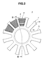
- Fig. 2 is a front view of a stator installed in the electric motor, that is taken from the direction of the arrow "II" of Fig. 1;
- Fig. 3 is a sectional view take along the line "III-III" of Fig. 2;
- Fig. 4 is a plan view of a part of the stator, that is taken from the direction of the arrow "IV" of Fig. 3;
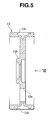
- Fig. 5 is a sectional view of a second case bracket member installed in the electric motor of the invention;
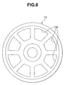
- Fig. 6 is a plan view of the second case bracket member, that is taken from the direction of the arrow "VI" of Fig. 5; and
- Fig. 7 is a sectional view of parts of a second discal rotor installed in the electric motor of the invention.
-
- In the following, the present invention will be described in detail with reference to the accompanying drawings.
- For ease of understanding, various directional terms, such as right, left, upper, lower, rightward, etc., are included in the following description. However, these terms are to be understood with respect to a drawing or drawings on which the corresponding part or portion is shown.
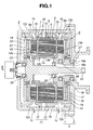
- Referring to Fig. 1, there is shown an electric motor 100 according to the present invention, which is of a two rotor single stator type.
- The electric motor 100 comprises a
cylindrical case 3 which consists of a bottomedcylindrical case member 1 and acircular lid member 2 which covers an open end ofcase member 1. Withincase 3, there are installed acylindrical stator 4 and first and seconddiscal rotors 5 and 6 which are arranged in such a manner as will be described hereinafter. - The
cylindrical stator 4 comprises generally anannular stator bracket 7 and a plurality ofstator elements 8 which are held onstator bracket 7. - The
annular stator bracket 7 comprises a cylindricalinner wall 7a and two axially spacedannular flanges 7b which extend radially outward from axial ends of the cylindricalinner wall 7a respectively. - As is seen from Figs. 2 to 4, both the
annular flanges 7b are formed with a plurality of paired andaligned cuts 7c which are arranged about an axis ofannular stator bracket 7 at evenly spaced intervals. As shown, each paired and alignedcuts 7c ofannular flanges 7b ofstator bracket 7 have thecorresponding stator element 8 installed therein. - As is seen from Fig. 3, each
stator element 8 comprises acore 9 including a plurality of ferromagnetic rectangular plates put on one another in a radial direction ofstator bracket 7, and acoil 10 wound aroundcore 9. - As is seen from Fig. 2, for assembling
stator 4, eachstator element 8 is inserted into the correspondingpaired cuts 7c ofannular flanges 7b from the outside of the same. - As is seen from Fig. 4, each core 9 (viz., combined ferromagnetic rectangular plates) is formed at both sides thereof with
rectangular recesses 9a which are tightly engaged with side edges ofcuts 7c ofannular flanges 7b ofstator bracket 7. With this engagement, axial displacement ofstator element 8 relative tostator bracket 7 is assuredly suppressed, which means that an axial positioning ofstator element 8 relative tostator bracket 7 is assured. - Referring back to Fig. 1, the
cylindrical stator 4 is coaxially and tightly held incylindrical case member 1 through anannular case bracket 11. More specifically, theannular case bracket 11 is tightly and concentrically installed incase member 1 having its cylindrical outer surface intimately contacting with an inner surface of acylindrical wall 1a ofcase member 1. - The
annular case bracket 11 is of a split structure including first and secondannular bracket members case member 1. The space betweenbracket members openings 29 formed incylindrical wall 1a ofcase 1. Although not shown in the drawing, power cables are led intocase 1 throughopenings 29 and connected withcoils 10 ofstator elements 8. - As shown in Fig. 1, first and second
annular bracket members cylindrical case member 1 andcircular lid member 2. Thus, positioning and tightening ofstator 4 incase 3 are assured. - That is, as will be described in detail hereinafter,
cylindrical stator 4 is tightly sandwiched atannular flanges 7b ofannular stator bracket 7 thereof betweenrespective recesses annular bracket members stator 4 relative tocase 3 is achieved.Respective pole portions 8a provided at axial ends ofcore 9 of eachstator element 8 are tightly held by first and secondannular bracket members stator 4 relative tocase 3 is achieved. - As is understood from Figs. 5 and 6 and Fig. 1, for holding
pole portions 8a of eachcore 9, each of first and secondannular bracket members 12 and 13 (onlybracket member 13 is shown) is formed with a plurality oftrapezoidal openings bracket member - Furthermore, as is seen Figs. 1 and 5, each of first and second
annular bracket members annular recess inner wall 7a and correspondingannular flange 7b ofannular stator bracket 7. Because of this arrangement,cylindrical stator 4 is tightly held incase 3 by means ofannular case bracket 11. - As is seen from Fig. 1, the first and second
annular bracket members annular case bracket 11 are formed, at cylindrical outer walls that contact the inner surface ofcylindrical wall 1a ofcylindrical case member 1, with respectiveannular grooves coolant passages pole portions 8a ofstator elements 8. For obtaining a sufficient heat exchanging between coolant incoolant passage corresponding pole portions 8a ofstator elements 8, eachcoolant passage - For feeding the coolant to
coolant passages cylindrical wall 1a ofcase member 1 is formed with twoinlet openings 1b which are exposed to given portions ofcoolant passages coolant passages cylindrical wall 1a ofcase member 1 is formed, at diametrically opposed portions ofinlet openings 1b, withoutlet openings 1c which are exposed to the other portions ofcoolant passages stator elements 8, especiallypole portions 8a thereof are effectively cooled by the coolant. - Referring to Fig. 1, first and second
discal rotors 5 and 6 are substantially the same in construction. That is, theserotors 5 and 6 are arranged at left and right positions ofcylindrical stator 4 as viewed in the drawing. It is to be noted that first discal rotor 5,cylindrical stator 4 and seconddiscal rotor 6 are coaxially arranged in order, as shown. - Referring to Fig. 7, there is shown, but in an exploded and sectional manner, the second
discal rotor 6 which comprises anannular magnet holder 14. The annularmagnetic holder 14 is formed with a plurality ofopenings 14a which are arranged around an axis ofannular magnet holder 14 at evenly spaced intervals. A corresponding number ofmagnets 15 are put in theopenings 14a, and annularmagnetic holder 14 thus havingmagnets 15 installed thereon is received in anannular recess 16a of a circularrotor base member 16. Anannular lid member 17 is put on annularmagnetic holder 14 and secured torotor base member 16 by means of bolts 18 (see Fig. 1) havingmagnets 15 inannular magnet holder 14 tightly put therebetween. Thus, seconddiscal rotor 6 is an assembled structure having a plurality ofmagnets 15 which are arranged about an axis of seconddiscal rotor 6 at evenly spaced intervals. - As is seen from Fig. 1, the first discal rotor 5 is substantially the same as the above-mentioned second
discal rotor 6 except for the shape of arotor base member 21 as will be described hereinafter. That is, the first discal rotor 5 comprises generally an annularmagnetic holder 19, a plurality of magnets 20 held bymagnet holder 19, an annularrotor base member 21 receiving a unit consisting ofmagnet holder 19 and magnets 20 and anannular lid member 22 secured torotor base member 21 by means ofbolts 23 having the unit tightly put therebetween. - However, as is seen from Fig. 1, annular
rotor base member 21 of first discal rotor 5 is integral with afirst output shaft 24 which extends axially through a center portion ofcasing 3. That is, circularrotor base member 21 is extends radially outward from a larger diameter left end offirst output shaft 24. As shown,first output shaft 24 is rotatably held incase 3 by both abearing 25 which is connected to the bottom wall ofcase member 1 and anotherbearing 26 which is connected to secondannular bracket member 13. As shown, a right end offirst output shaft 24 passes through a center opening ofcircular lid member 2 to be exposed to the outside ofcase 3. Although not shown in the drawing, the exposed right end offirst output shaft 24 is connected to a driven member to rotate together with the same. - While, as is seen from Figs. 1 and 7,
rotator base member 16 of seconddiscal rotor 6 is formed with acenter boss portion 16a which is opened and rotatably held incase 3 by both abearing 27 which is connected tocircular lid member 2 and another being 28 which is connected to secondannular bracket member 13. The openedcenter boss portion 16a is concentrically disposed about a smaller diameter right end portion offirst output shaft 24 keeping a cylindrical clearance therebetween. The opening ofcenter boss portion 16a is splined (16b) for connecting with a left end of a second output shaft (not shown) which also passes through the center opening ofcircular lid member 2. Of course, second output shaft is constructed of a hollow member for concentrically receiving therein the right end portion offirst output shaft 24. Thus, when seconddiscal rotor 6 is rotated, the second output shaft is rotated about and relative tofirst output shaft 24. - When, now, coils 10 of
stator 4 are supplied with compound electric current through the power cables connected thereto, first and secondannular rotors 5 and 6 are driven or rotated about a common axis which first andsecond output shafts 24 commonly have. By controlling the compound electric current, rotation of first discal rotor 5 and that of seconddiscal rotor 6, and thus, rotation offirst output shaft 24 and that of the second output shaft are individually controlled. - In the following, advantageous features of electric motor 100 of the present invention will be described.
- As is described hereinabove and as is easily understood from Fig. 1, within
case 3, there are installedcylindrical stator 4 which is immovably set therein and first and second discal rotors 5 which are rotatably arranged at axially opposed end portions ofcylindrical stator 4. Tight holding ofstator 4 incase 3 is achieved by using first and secondannular bracket members inner surface 1a ofcase member 1. Rotation of first discal rotor 5 is transmitted to a first external driven member (not shown) throughfirst output shaft 24 which extends rightward in Fig. 1 through a center bore ofcase 3, and rotation of seconddiscal rotor 6 is transmitted to a second external driven member (not shown) through the second output shaft (not shown) which extends in the same direction as first output shaft while covering the same. - That is, the
stator 4 is stably held by two supporting means that are first and secondannular bracket members case 3. In other words, unlike the stator of the electric motor in above-mentioned Japanese Patent First Provisional Publication 2000-14086, axially opposed end portions ofstator 4 are tightly supported bycase 3 through respective supportingmembers stator 4 incase 3 is readily achieved by the above-mentioned construction that is simpler than that of the publication, which brings about an advantage in cost. - Cooling of
stator elements 8 is carried out by flowing coolant inannular grooves annular bracket members annular bracket members such grooves - First and second
discal rotors 5 and 6 are respectively positioned at axial ends ofstator 4. Eachrotor 5 or 6 has no part that covers the cylindrical outer surface ofstator 4. Thus, unlike the case of the electric motor of the above-mentioned publication, the space forstator 4 is not affected by the size ofrotors 5 and 6. That is, the size ofstator 4 can be freely increased when needed. - In
stator 4, all ofstator elements 8 are held by thecommon stator bracket 7. This means that the stator can be previously assembled before the same is put intocase 3. This production procedure improves the work for assembling the electric motor 100. - Radial positioning of each
stator element 8 relative tocase 3 is achieved by engagement ofpole portions 8a thereof withopenings annular bracket members stator element 8 relative tocase 3 is achieved by engagement ofrectangular recess 9a (see Fig. 4) with edges ofcuts 7c of annular flanges ofstator bracket 7. This means that positioning ofstator 4 incase 3 is assuredly made. Due to provision ofrectangular recess 9a in eachstator element 8 andcuts 7c of annular flanges ofstator bracket 7, which are latchably engageable as shown in Fig. 4, the work for mountingstator elements 8 onto tostator bracket 7 is easily achieved. - As is seen from Fig. 1, due to engagement of the junction portions between cylindrical inner wall and
annular flanges 7b ofstator bracket 7 withannular recesses annular bracket members stator 4 relative tocase 3 is much assured. - Before being inserted into
case member 1,stator 4 and first and secondannular bracket members stator elements 8 are tightly fixed tostator bracket 7. Accordingly, subsequent work for inserting the unit intocase member 1 is easily and speedily carried out. - The
coolant passages annular bracket members stator elements 8, particularlypole portions 8a thereof which are easily heated, are effectively cooled by coolant flowing incoolant passages - The entire contents of Japanese Patent Application 2001-271565 filed September 7, 2001 are incorporated herein by reference.
- Although the invention has been described above with reference to the embodiment of the invention, the invention is not limited to such embodiment as described above. Various modifications and variations of such embodiment may be carried out by those skilled in the art, in light of the above description.
Claims (12)
- An electric motor comprising:a case (3);a cylindrical stator (4) which is installed in the cylindrical case;first and second discal rotors (5, 6) which are installed in the case and arranged at axially opposed end portions of the cylindrical stator (4) respectively to rotate about an axis of the cylindrical stator; anda case bracket (11) which is installed in the case to support the cylindrical stator (4) relative to the case (3), the case bracket (11) being in abutment with an inner surface of the case to be held in the case.
- An electric motor as claimed in Claim 1, in which the case (3) is cylindrical in shape, the cylindrical stator (4) is concentrically disposed in the cylindrical case (3) and the case bracket (11) is annular in shape and contacts at a cylindrical outer surface thereof with the inner surface of a cylindrical wall (1a) of the cylindrical case (3).
- An electric motor as claimed in Claim 1 or 2, in which the cylindrical stator (4) comprises:an annular stator bracket (7);a plurality of stator elements (8) held by the annular stator bracket, the stator elements being arranged around an axis of the annular stator bracket at evenly spaced intervals;a first structure (8a, 12a) through which axial end portions (8a) of each of the stator elements (8) are in abutment with the case bracket (11) thereby to achieve a radial positioning of the stator (4) relative to the cylindrical case; anda second structure (7a, 12b, 13b) through which the annular stator bracket (7) is in abutment with the annular case bracket (11) thereby to achieve an axial positioning of the stator (4) relative to the cylindrical case.
- An electric motor as claimed in Claim 3, in which the annular stator bracket (7) is formed with a plurality of cuts (7c) which are arranged around an axis of the annular stator bracket (7) at evenly spaced intervals for putting therein the stator elements (8) respectively, the cuts (7c) extending radially inward from a peripheral portion of the annular stator bracket (7) to permit insertion of the stator elements (8) thereinto from the peripheral portion.
- An electric motor as claimed in Claim 4, in which each of the stator elements (8) is formed at opposed sides thereof with paired rectangular recesses (9a) which are latchably engaged with given portions (7b) of the annular stator bracket '7) when the stator element is inserted into the corresponding cut (7c), thereby to establish an axial positioning of the stator element (8) relative to the annular stator bracket (7).
- An electric motor as claimed in Claim 3, 4 or 5, in which a radially inward portion of the annular stator bracket (7) is in abutment with a radially inward portion of the case bracket (11) thereby to establish a radial positioning of the stator bracket relative to the cylindrical case.
- An electric motor as claimed in Claim 3, 4 or 5, in which the cylindrical case bracket (11) comprises first and second annular bracket members (12, 13) which are tightly received in the cylindrical case (3) having the cylindrical stator (4) intimately put therebetween.
- An electric motor as claimed in Claim 7, in which axial end portions (8a) of each stator element (8) held by the annular stator bracket (7) are respectively and intimately received in aligned openings (12a, 13a) formed in said first and second annular bracket members (12, 13) of the cylindrical case (11), thereby to achieve a radial positioning of the cylindrical stator (4) relative to the cylindrical case (3).
- An electric motor as claimed in Claim 7 or 8, in which axially opposed portions of a radially inward part of the annular stator bracket (7) are intimately and respectively put in recesses (12b, 13b) respectively formed in said first and second annular bracket members (12, 13) of the cylindrical case, thereby to achieve an axial positioning of the cylindrical stator (4) relative to the cylindrical case (3).
- An electric motor as claimed in Claim 2, 3, 4, 5, 6, 7, 8 or 9, in which the cylindrical case bracket (11) is formed at its cylindrical outer surface with at least one coolant following annular groove (12c, 13c) which extends around the cylindrical stator (4).
- An electric motor as claimed in Claim 7, 8, 9 or 10, in which the first and second annular bracket members (12, 13) of the case bracket (11) are respectively formed at cylindrical outer surfaces thereof with coolant flowing annular grooves (12c, 13c) which extend around the cylindrical stator (4) in the vicinity of axial ends of the stator elements.
- An electric motor comprising:a cylindrical case (3);a cylindrical stator (4) which is concentrically installed in the cylindrical case, said stator having a cylindrical center bore;first and second discal rotors (5, 6) which are installed in the cylindrical case and respectively arranged at axially opposed end portions of the cylindrical stator to rotate about a common axis;a hollow output member (16a) having the second discal rotor (6) concentrically mounted thereon;an output shaft (24) passing through the cylindrical center bore of the cylindrical stator (4) and having one end portion on which the first discal rotor (5) is concentrically mounted and the other end portion around which the hollow output member (16a) is concentrically disposed keeping a cylindrical space therebetween; andfirst and second annular bracket members (12, 13) which are tightly and concentrically disposed in the cylindrical case (3) in a manner to put therebetween the cylindrical stator (4) to hold the cylindrical stator relative to the cylindrical case.
Applications Claiming Priority (2)
| Application Number | Priority Date | Filing Date | Title |
|---|---|---|---|
| JP2001271565A JP3702825B2 (en) | 2001-09-07 | 2001-09-07 | Stator support structure for rotating electrical machines |
| JP2001271565 | 2001-09-07 |
Publications (2)
| Publication Number | Publication Date |
|---|---|
| EP1292004A1 true EP1292004A1 (en) | 2003-03-12 |
| EP1292004B1 EP1292004B1 (en) | 2006-12-20 |
Family
ID=19097056
Family Applications (1)
| Application Number | Title | Priority Date | Filing Date |
|---|---|---|---|
| EP02020075A Expired - Fee Related EP1292004B1 (en) | 2001-09-07 | 2002-09-06 | Two rotor single stator type electric motor |
Country Status (4)
| Country | Link |
|---|---|
| US (1) | US6774527B2 (en) |
| EP (1) | EP1292004B1 (en) |
| JP (1) | JP3702825B2 (en) |
| DE (1) | DE60216863T2 (en) |
Cited By (10)
| Publication number | Priority date | Publication date | Assignee | Title |
|---|---|---|---|---|
| WO2004042891A1 (en) * | 2002-11-07 | 2004-05-21 | Brose Fahrzeugteile Gmbh & Co. Kg, Coburg | Permanent-magnet machine having an axial air gap |
| EP1612913A3 (en) * | 2004-06-29 | 2006-03-29 | Nissan Motor Company, Limited | Permanent magnet rotor of an axial gap motor and manufacturing method |
| EP1835597A3 (en) * | 2006-03-13 | 2007-09-26 | ISCA Innovations, Inc. | Brushless Electric Motor |
| WO2008068503A2 (en) * | 2006-12-07 | 2008-06-12 | Cranfield University | Axial flux electrical machines |
| EP2061137A1 (en) * | 2007-11-19 | 2009-05-20 | Siemens Aktiengesellschaft | Method for mechanically connecting a disk motor |
| WO2010092402A1 (en) * | 2009-02-13 | 2010-08-19 | Isis Innovation Ltd | Electric machine- modular |
| US9054566B2 (en) | 2009-04-14 | 2015-06-09 | Isis Innovation Ltd | Electric machine—evaporative cooling |
| US9071117B2 (en) | 2009-02-13 | 2015-06-30 | Isis Innovation Ltd. | Electric machine—flux |
| US9496776B2 (en) | 2009-02-13 | 2016-11-15 | Oxford University Innovation Limited | Cooled electric machine |
| EP3940932A4 (en) * | 2019-08-26 | 2022-06-08 | Midea Welling Motor Technology (Shanghai) Co., Ltd | Motor and fan |
Families Citing this family (17)
| Publication number | Priority date | Publication date | Assignee | Title |
|---|---|---|---|---|
| US7154192B2 (en) * | 2004-09-27 | 2006-12-26 | General Electric Company | Electrical machine with double-sided lamination stack |
| US7154191B2 (en) * | 2004-06-30 | 2006-12-26 | General Electric Company | Electrical machine with double-sided rotor |
| EP1624554A1 (en) | 2004-08-02 | 2006-02-08 | Nissan Motor Co., Ltd. | Rotating electric machine |
| JP2006050745A (en) | 2004-08-03 | 2006-02-16 | Nissan Motor Co Ltd | Axial gap rotary electric machine |
| JP4882211B2 (en) | 2004-08-06 | 2012-02-22 | 日産自動車株式会社 | Axial gap motor structure |
| US7548008B2 (en) * | 2004-09-27 | 2009-06-16 | General Electric Company | Electrical machine with double-sided lamination stack |
| US7839048B2 (en) * | 2004-09-27 | 2010-11-23 | General Electric Company | Electrical machine with double-sided stator |
| US7692357B2 (en) | 2004-12-16 | 2010-04-06 | General Electric Company | Electrical machines and assemblies including a yokeless stator with modular lamination stacks |
| JP4720980B2 (en) * | 2005-04-13 | 2011-07-13 | 株式会社富士通ゼネラル | Axial air gap type electric motor |
| JP4720288B2 (en) * | 2005-05-24 | 2011-07-13 | 日産自動車株式会社 | Rotating electric machine stator |
| JP4935285B2 (en) * | 2006-10-04 | 2012-05-23 | 日産自動車株式会社 | Stator structure of axial gap type rotating electrical machine |
| JP2008131683A (en) * | 2006-11-16 | 2008-06-05 | Fujitsu General Ltd | Axial air gap type motor |
| US20100283347A1 (en) * | 2009-05-07 | 2010-11-11 | Clynton Caines | Novel ganged alternating current generator |
| GB201013881D0 (en) * | 2010-08-19 | 2010-10-06 | Oxford Yasa Motors Ltd | Electric machine - construction |
| KR20160000909A (en) * | 2014-06-25 | 2016-01-06 | 현대모비스 주식회사 | Water-cooled moter |
| CN105576927B (en) * | 2016-03-09 | 2019-01-15 | 深圳小象电动科技有限公司 | The disc-type electric motor that stator immersion oil radiates and rotor is built-in |
| KR101979341B1 (en) * | 2018-05-31 | 2019-05-16 | (주)이플로우 | Permanent axial flux magnet motor |
Citations (8)
| Publication number | Priority date | Publication date | Assignee | Title |
|---|---|---|---|---|
| US4387335A (en) * | 1981-07-27 | 1983-06-07 | Fisher Charles B | Constant-frequency dynamo with stationary armature |
| US4959578A (en) * | 1987-11-24 | 1990-09-25 | Axial Electric, Inc. | Dual rotor axial air gap induction motor |
| EP0480721A2 (en) * | 1990-10-10 | 1992-04-15 | Westinghouse Electric Corporation | Structureborne vibration-compensation motor arrangement having back-to-back twin ac motors |
| JPH05268754A (en) * | 1992-03-18 | 1993-10-15 | Toshiba Corp | Axial gap electric rotating machine |
| WO1996004094A2 (en) * | 1994-07-22 | 1996-02-15 | Woodward Richard C Jr | Disc-type electrical machine |
| US5973436A (en) * | 1996-08-08 | 1999-10-26 | Rolls-Royce Power Engineering Plc | Electrical machine |
| DE19954196A1 (en) * | 1998-12-28 | 2000-06-29 | Feldmann Johann | Electromagnetic energy converter preferably synchronous machine, has annular core winding with conical narrowing from inner to outer core periphery, and rotor plate surfaces carrying permanent magnets inclined accordingly |
| FR2793083A1 (en) * | 1999-04-30 | 2000-11-03 | Valeo Equip Electr Moteur | Motor vehicle alternator which is cooled by an internal fluid and quiet in operation |
Family Cites Families (4)
| Publication number | Priority date | Publication date | Assignee | Title |
|---|---|---|---|---|
| GB8810898D0 (en) * | 1988-05-09 | 1988-06-15 | Bespak Plc | Improvements in dispensing apparatus |
| US5334899A (en) * | 1991-09-30 | 1994-08-02 | Dymytro Skybyk | Polyphase brushless DC and AC synchronous machines |
| US5767600A (en) * | 1997-02-27 | 1998-06-16 | Whiteley; Eric | Modular motor |
| JP3559891B2 (en) * | 1998-06-22 | 2004-09-02 | 日産自動車株式会社 | Cooling structure of multilayer motor |
-
2001
- 2001-09-07 JP JP2001271565A patent/JP3702825B2/en not_active Expired - Fee Related
-
2002
- 2002-09-06 US US10/235,484 patent/US6774527B2/en not_active Expired - Lifetime
- 2002-09-06 DE DE60216863T patent/DE60216863T2/en not_active Expired - Lifetime
- 2002-09-06 EP EP02020075A patent/EP1292004B1/en not_active Expired - Fee Related
Patent Citations (8)
| Publication number | Priority date | Publication date | Assignee | Title |
|---|---|---|---|---|
| US4387335A (en) * | 1981-07-27 | 1983-06-07 | Fisher Charles B | Constant-frequency dynamo with stationary armature |
| US4959578A (en) * | 1987-11-24 | 1990-09-25 | Axial Electric, Inc. | Dual rotor axial air gap induction motor |
| EP0480721A2 (en) * | 1990-10-10 | 1992-04-15 | Westinghouse Electric Corporation | Structureborne vibration-compensation motor arrangement having back-to-back twin ac motors |
| JPH05268754A (en) * | 1992-03-18 | 1993-10-15 | Toshiba Corp | Axial gap electric rotating machine |
| WO1996004094A2 (en) * | 1994-07-22 | 1996-02-15 | Woodward Richard C Jr | Disc-type electrical machine |
| US5973436A (en) * | 1996-08-08 | 1999-10-26 | Rolls-Royce Power Engineering Plc | Electrical machine |
| DE19954196A1 (en) * | 1998-12-28 | 2000-06-29 | Feldmann Johann | Electromagnetic energy converter preferably synchronous machine, has annular core winding with conical narrowing from inner to outer core periphery, and rotor plate surfaces carrying permanent magnets inclined accordingly |
| FR2793083A1 (en) * | 1999-04-30 | 2000-11-03 | Valeo Equip Electr Moteur | Motor vehicle alternator which is cooled by an internal fluid and quiet in operation |
Non-Patent Citations (1)
| Title |
|---|
| PATENT ABSTRACTS OF JAPAN vol. 018, no. 047 (E - 1496) 25 January 1994 (1994-01-25) * |
Cited By (16)
| Publication number | Priority date | Publication date | Assignee | Title |
|---|---|---|---|---|
| WO2004042891A1 (en) * | 2002-11-07 | 2004-05-21 | Brose Fahrzeugteile Gmbh & Co. Kg, Coburg | Permanent-magnet machine having an axial air gap |
| EP1612913A3 (en) * | 2004-06-29 | 2006-03-29 | Nissan Motor Company, Limited | Permanent magnet rotor of an axial gap motor and manufacturing method |
| US7355311B2 (en) | 2004-06-29 | 2008-04-08 | Nissan Motor Co., Ltd. | Rotor of axial gap motor and method of producing same |
| CN100442637C (en) * | 2004-06-29 | 2008-12-10 | 日产自动车株式会社 | Rotor of axial gap motor and method of producing same |
| EP1835597A3 (en) * | 2006-03-13 | 2007-09-26 | ISCA Innovations, Inc. | Brushless Electric Motor |
| US7471026B2 (en) | 2006-03-13 | 2008-12-30 | Isca Innovatons, Llc | Brushless electric motor |
| WO2008068503A2 (en) * | 2006-12-07 | 2008-06-12 | Cranfield University | Axial flux electrical machines |
| WO2008068503A3 (en) * | 2006-12-07 | 2008-08-07 | Univ Cranfield | Axial flux electrical machines |
| EP2061137A1 (en) * | 2007-11-19 | 2009-05-20 | Siemens Aktiengesellschaft | Method for mechanically connecting a disk motor |
| WO2010092402A1 (en) * | 2009-02-13 | 2010-08-19 | Isis Innovation Ltd | Electric machine- modular |
| US9071117B2 (en) | 2009-02-13 | 2015-06-30 | Isis Innovation Ltd. | Electric machine—flux |
| US9318938B2 (en) | 2009-02-13 | 2016-04-19 | Isis Innovation Ltd. | Electric machine-modular |
| US9496776B2 (en) | 2009-02-13 | 2016-11-15 | Oxford University Innovation Limited | Cooled electric machine |
| US9054566B2 (en) | 2009-04-14 | 2015-06-09 | Isis Innovation Ltd | Electric machine—evaporative cooling |
| EP3940932A4 (en) * | 2019-08-26 | 2022-06-08 | Midea Welling Motor Technology (Shanghai) Co., Ltd | Motor and fan |
| US11863030B2 (en) | 2019-08-26 | 2024-01-02 | Midea Welling Motor Technology (Shanghai) Co., Ltd. | Motor and fan |
Also Published As
| Publication number | Publication date |
|---|---|
| DE60216863T2 (en) | 2007-04-19 |
| JP2003088032A (en) | 2003-03-20 |
| US20030048034A1 (en) | 2003-03-13 |
| US6774527B2 (en) | 2004-08-10 |
| DE60216863D1 (en) | 2007-02-01 |
| EP1292004B1 (en) | 2006-12-20 |
| JP3702825B2 (en) | 2005-10-05 |
Similar Documents
| Publication | Publication Date | Title |
|---|---|---|
| US6774527B2 (en) | Two rotor single stator type electric motor | |
| US6943473B2 (en) | Electric rotating machine | |
| US7256524B2 (en) | Axial gap electric motor | |
| US7256526B1 (en) | Integrated stator-axle for in-wheel motor of an electric vehicle | |
| JP5319333B2 (en) | Electric motor | |
| JP5354888B2 (en) | Brushless motor | |
| EP1450464B1 (en) | Axial gap type dynamo-electric machine | |
| EP1946432B1 (en) | Electric motor | |
| US7504753B2 (en) | Motor | |
| JP5814249B2 (en) | Electric motor assembly | |
| CN101663807B (en) | Rotor for rotating machine | |
| EP2658098A1 (en) | Rotator | |
| US20090127972A1 (en) | Brushless motor | |
| WO2006068042A1 (en) | Axial gap motor | |
| US20130057102A1 (en) | Rotor and motor | |
| JP2017099181A (en) | Axial-gap dynamo-electric machine | |
| EP1496598B1 (en) | Claw-pole type stepping motor having radial dimension reduced without detriment to performance characteristic | |
| JP2017192201A (en) | Stator of rotary electric machine | |
| JP6402739B2 (en) | Rotating electric machine | |
| US20240063697A1 (en) | Motor, and method for manufacturing motor | |
| US7781928B2 (en) | Brushless motor | |
| JP2023515761A (en) | motor | |
| JP2005269831A (en) | Brushless dc motor | |
| JP2023061074A (en) | Buried-type magnetic motor | |
| JPH0965602A (en) | Small-sized motor |
Legal Events
| Date | Code | Title | Description |
|---|---|---|---|
| PUAI | Public reference made under article 153(3) epc to a published international application that has entered the european phase |
Free format text: ORIGINAL CODE: 0009012 |
|
| 17P | Request for examination filed |
Effective date: 20020906 |
|
| AK | Designated contracting states |
Kind code of ref document: A1 Designated state(s): AT BE BG CH CY CZ DE DK EE ES FI FR GB GR IE IT LI LU MC NL PT SE SK TR |
|
| AX | Request for extension of the european patent |
Extension state: AL LT LV MK RO SI |
|
| AKX | Designation fees paid |
Designated state(s): DE FR GB |
|
| 17Q | First examination report despatched |
Effective date: 20040105 |
|
| GRAP | Despatch of communication of intention to grant a patent |
Free format text: ORIGINAL CODE: EPIDOSNIGR1 |
|
| GRAS | Grant fee paid |
Free format text: ORIGINAL CODE: EPIDOSNIGR3 |
|
| GRAA | (expected) grant |
Free format text: ORIGINAL CODE: 0009210 |
|
| AK | Designated contracting states |
Kind code of ref document: B1 Designated state(s): DE FR GB |
|
| REG | Reference to a national code |
Ref country code: GB Ref legal event code: FG4D |
|
| REF | Corresponds to: |
Ref document number: 60216863 Country of ref document: DE Date of ref document: 20070201 Kind code of ref document: P |
|
| ET | Fr: translation filed | ||
| PLBE | No opposition filed within time limit |
Free format text: ORIGINAL CODE: 0009261 |
|
| STAA | Information on the status of an ep patent application or granted ep patent |
Free format text: STATUS: NO OPPOSITION FILED WITHIN TIME LIMIT |
|
| 26N | No opposition filed |
Effective date: 20070921 |
|
| REG | Reference to a national code |
Ref country code: FR Ref legal event code: PLFP Year of fee payment: 15 |
|
| REG | Reference to a national code |
Ref country code: FR Ref legal event code: PLFP Year of fee payment: 16 |
|
| REG | Reference to a national code |
Ref country code: FR Ref legal event code: PLFP Year of fee payment: 17 |
|
| PGFP | Annual fee paid to national office [announced via postgrant information from national office to epo] |
Ref country code: DE Payment date: 20190827 Year of fee payment: 18 Ref country code: FR Payment date: 20190815 Year of fee payment: 18 |
|
| PGFP | Annual fee paid to national office [announced via postgrant information from national office to epo] |
Ref country code: GB Payment date: 20190905 Year of fee payment: 18 |
|
| REG | Reference to a national code |
Ref country code: DE Ref legal event code: R119 Ref document number: 60216863 Country of ref document: DE |
|
| GBPC | Gb: european patent ceased through non-payment of renewal fee |
Effective date: 20200906 |
|
| PG25 | Lapsed in a contracting state [announced via postgrant information from national office to epo] |
Ref country code: DE Free format text: LAPSE BECAUSE OF NON-PAYMENT OF DUE FEES Effective date: 20210401 Ref country code: FR Free format text: LAPSE BECAUSE OF NON-PAYMENT OF DUE FEES Effective date: 20200930 |
|
| PG25 | Lapsed in a contracting state [announced via postgrant information from national office to epo] |
Ref country code: GB Free format text: LAPSE BECAUSE OF NON-PAYMENT OF DUE FEES Effective date: 20200906 |