EP1291952A1 - Battery - Google Patents
Battery Download PDFInfo
- Publication number
- EP1291952A1 EP1291952A1 EP01934497A EP01934497A EP1291952A1 EP 1291952 A1 EP1291952 A1 EP 1291952A1 EP 01934497 A EP01934497 A EP 01934497A EP 01934497 A EP01934497 A EP 01934497A EP 1291952 A1 EP1291952 A1 EP 1291952A1
- Authority
- EP
- European Patent Office
- Prior art keywords
- battery
- resin layer
- separator
- positive electrode
- negative electrode
- Prior art date
- Legal status (The legal status is an assumption and is not a legal conclusion. Google has not performed a legal analysis and makes no representation as to the accuracy of the status listed.)
- Withdrawn
Links
- 229920005989 resin Polymers 0.000 claims abstract description 65
- 239000011347 resin Substances 0.000 claims abstract description 65
- 239000000945 filler Substances 0.000 claims abstract description 13
- 239000007787 solid Substances 0.000 claims abstract description 13
- 239000000463 material Substances 0.000 claims abstract description 6
- 239000010410 layer Substances 0.000 claims description 57
- 239000000843 powder Substances 0.000 claims description 24
- -1 polyethylene Polymers 0.000 claims description 20
- PNEYBMLMFCGWSK-UHFFFAOYSA-N aluminium oxide Inorganic materials [O-2].[O-2].[O-2].[Al+3].[Al+3] PNEYBMLMFCGWSK-UHFFFAOYSA-N 0.000 claims description 13
- 229920001577 copolymer Polymers 0.000 claims description 13
- 239000000919 ceramic Substances 0.000 claims description 12
- BQCIDUSAKPWEOX-UHFFFAOYSA-N 1,1-Difluoroethene Chemical compound FC(F)=C BQCIDUSAKPWEOX-UHFFFAOYSA-N 0.000 claims description 9
- HCDGVLDPFQMKDK-UHFFFAOYSA-N hexafluoropropylene Chemical group FC(F)=C(F)C(F)(F)F HCDGVLDPFQMKDK-UHFFFAOYSA-N 0.000 claims description 7
- BFKJFAAPBSQJPD-UHFFFAOYSA-N tetrafluoroethene Chemical group FC(F)=C(F)F BFKJFAAPBSQJPD-UHFFFAOYSA-N 0.000 claims description 6
- 239000004698 Polyethylene Substances 0.000 claims description 5
- VYPSYNLAJGMNEJ-UHFFFAOYSA-N Silicium dioxide Chemical compound O=[Si]=O VYPSYNLAJGMNEJ-UHFFFAOYSA-N 0.000 claims description 4
- GWEVSGVZZGPLCZ-UHFFFAOYSA-N Titan oxide Chemical compound O=[Ti]=O GWEVSGVZZGPLCZ-UHFFFAOYSA-N 0.000 claims description 4
- MCMNRKCIXSYSNV-UHFFFAOYSA-N Zirconium dioxide Chemical compound O=[Zr]=O MCMNRKCIXSYSNV-UHFFFAOYSA-N 0.000 claims description 4
- 229920000573 polyethylene Polymers 0.000 claims description 4
- 229920002981 polyvinylidene fluoride Polymers 0.000 claims description 4
- 239000011164 primary particle Substances 0.000 claims description 3
- 239000002344 surface layer Substances 0.000 claims description 3
- 229920003171 Poly (ethylene oxide) Polymers 0.000 claims description 2
- 239000004743 Polypropylene Substances 0.000 claims description 2
- 229920001328 Polyvinylidene chloride Polymers 0.000 claims description 2
- UUAGAQFQZIEFAH-UHFFFAOYSA-N chlorotrifluoroethylene Chemical group FC(F)=C(F)Cl UUAGAQFQZIEFAH-UHFFFAOYSA-N 0.000 claims description 2
- 229920002239 polyacrylonitrile Polymers 0.000 claims description 2
- 229920001155 polypropylene Polymers 0.000 claims description 2
- 239000000377 silicon dioxide Substances 0.000 claims description 2
- 239000011255 nonaqueous electrolyte Substances 0.000 claims 1
- 230000000052 comparative effect Effects 0.000 description 15
- 239000002131 composite material Substances 0.000 description 9
- 239000005001 laminate film Substances 0.000 description 6
- 239000002245 particle Substances 0.000 description 6
- 230000002035 prolonged effect Effects 0.000 description 6
- SECXISVLQFMRJM-UHFFFAOYSA-N N-Methylpyrrolidone Chemical compound CN1CCCC1=O SECXISVLQFMRJM-UHFFFAOYSA-N 0.000 description 5
- 239000000203 mixture Substances 0.000 description 5
- 239000000853 adhesive Substances 0.000 description 4
- 230000001070 adhesive effect Effects 0.000 description 4
- 238000007599 discharging Methods 0.000 description 4
- 239000003792 electrolyte Substances 0.000 description 4
- 238000000635 electron micrograph Methods 0.000 description 4
- 230000000694 effects Effects 0.000 description 3
- OKTJSMMVPCPJKN-UHFFFAOYSA-N Carbon Chemical compound [C] OKTJSMMVPCPJKN-UHFFFAOYSA-N 0.000 description 2
- HBBGRARXTFLTSG-UHFFFAOYSA-N Lithium ion Chemical compound [Li+] HBBGRARXTFLTSG-UHFFFAOYSA-N 0.000 description 2
- XAGFODPZIPBFFR-UHFFFAOYSA-N aluminium Chemical compound [Al] XAGFODPZIPBFFR-UHFFFAOYSA-N 0.000 description 2
- 229910052782 aluminium Inorganic materials 0.000 description 2
- 239000011230 binding agent Substances 0.000 description 2
- 238000003411 electrode reaction Methods 0.000 description 2
- 229910001416 lithium ion Inorganic materials 0.000 description 2
- 229920000139 polyethylene terephthalate Polymers 0.000 description 2
- 239000011148 porous material Substances 0.000 description 2
- 230000000717 retained effect Effects 0.000 description 2
- 239000002904 solvent Substances 0.000 description 2
- DBCAQXHNJOFNGC-UHFFFAOYSA-N 4-bromo-1,1,1-trifluorobutane Chemical compound FC(F)(F)CCCBr DBCAQXHNJOFNGC-UHFFFAOYSA-N 0.000 description 1
- 238000004438 BET method Methods 0.000 description 1
- RYGMFSIKBFXOCR-UHFFFAOYSA-N Copper Chemical compound [Cu] RYGMFSIKBFXOCR-UHFFFAOYSA-N 0.000 description 1
- OIFBSDVPJOWBCH-UHFFFAOYSA-N Diethyl carbonate Chemical compound CCOC(=O)OCC OIFBSDVPJOWBCH-UHFFFAOYSA-N 0.000 description 1
- KMTRUDSVKNLOMY-UHFFFAOYSA-N Ethylene carbonate Chemical compound O=C1OCCO1 KMTRUDSVKNLOMY-UHFFFAOYSA-N 0.000 description 1
- 229910032387 LiCoO2 Inorganic materials 0.000 description 1
- 229910001290 LiPF6 Inorganic materials 0.000 description 1
- VVQNEPGJFQJSBK-UHFFFAOYSA-N Methyl methacrylate Chemical compound COC(=O)C(C)=C VVQNEPGJFQJSBK-UHFFFAOYSA-N 0.000 description 1
- 239000006230 acetylene black Substances 0.000 description 1
- 239000012790 adhesive layer Substances 0.000 description 1
- IZJSTXINDUKPRP-UHFFFAOYSA-N aluminum lead Chemical compound [Al].[Pb] IZJSTXINDUKPRP-UHFFFAOYSA-N 0.000 description 1
- 230000004888 barrier function Effects 0.000 description 1
- CKFRRHLHAJZIIN-UHFFFAOYSA-N cobalt lithium Chemical compound [Li].[Co] CKFRRHLHAJZIIN-UHFFFAOYSA-N 0.000 description 1
- 239000004020 conductor Substances 0.000 description 1
- 239000011889 copper foil Substances 0.000 description 1
- 238000001035 drying Methods 0.000 description 1
- 239000000839 emulsion Substances 0.000 description 1
- 230000002708 enhancing effect Effects 0.000 description 1
- STVZJERGLQHEKB-UHFFFAOYSA-N ethylene glycol dimethacrylate Substances CC(=C)C(=O)OCCOC(=O)C(C)=C STVZJERGLQHEKB-UHFFFAOYSA-N 0.000 description 1
- 239000011888 foil Substances 0.000 description 1
- 238000000034 method Methods 0.000 description 1
- 239000007773 negative electrode material Substances 0.000 description 1
- 239000005486 organic electrolyte Substances 0.000 description 1
- 239000005020 polyethylene terephthalate Substances 0.000 description 1
- 239000007774 positive electrode material Substances 0.000 description 1
- 238000002360 preparation method Methods 0.000 description 1
- 239000011241 protective layer Substances 0.000 description 1
- 238000009877 rendering Methods 0.000 description 1
- 238000004804 winding Methods 0.000 description 1
Images


Classifications
-
- H—ELECTRICITY
- H01—ELECTRIC ELEMENTS
- H01M—PROCESSES OR MEANS, e.g. BATTERIES, FOR THE DIRECT CONVERSION OF CHEMICAL ENERGY INTO ELECTRICAL ENERGY
- H01M10/00—Secondary cells; Manufacture thereof
- H01M10/04—Construction or manufacture in general
- H01M10/0431—Cells with wound or folded electrodes
-
- H—ELECTRICITY
- H01—ELECTRIC ELEMENTS
- H01M—PROCESSES OR MEANS, e.g. BATTERIES, FOR THE DIRECT CONVERSION OF CHEMICAL ENERGY INTO ELECTRICAL ENERGY
- H01M50/00—Constructional details or processes of manufacture of the non-active parts of electrochemical cells other than fuel cells, e.g. hybrid cells
- H01M50/40—Separators; Membranes; Diaphragms; Spacing elements inside cells
- H01M50/489—Separators, membranes, diaphragms or spacing elements inside the cells, characterised by their physical properties, e.g. swelling degree, hydrophilicity or shut down properties
- H01M50/491—Porosity
-
- H—ELECTRICITY
- H01—ELECTRIC ELEMENTS
- H01M—PROCESSES OR MEANS, e.g. BATTERIES, FOR THE DIRECT CONVERSION OF CHEMICAL ENERGY INTO ELECTRICAL ENERGY
- H01M10/00—Secondary cells; Manufacture thereof
- H01M10/05—Accumulators with non-aqueous electrolyte
- H01M10/052—Li-accumulators
- H01M10/0525—Rocking-chair batteries, i.e. batteries with lithium insertion or intercalation in both electrodes; Lithium-ion batteries
-
- H—ELECTRICITY
- H01—ELECTRIC ELEMENTS
- H01M—PROCESSES OR MEANS, e.g. BATTERIES, FOR THE DIRECT CONVERSION OF CHEMICAL ENERGY INTO ELECTRICAL ENERGY
- H01M50/00—Constructional details or processes of manufacture of the non-active parts of electrochemical cells other than fuel cells, e.g. hybrid cells
- H01M50/10—Primary casings; Jackets or wrappings
- H01M50/116—Primary casings; Jackets or wrappings characterised by the material
- H01M50/124—Primary casings; Jackets or wrappings characterised by the material having a layered structure
-
- H—ELECTRICITY
- H01—ELECTRIC ELEMENTS
- H01M—PROCESSES OR MEANS, e.g. BATTERIES, FOR THE DIRECT CONVERSION OF CHEMICAL ENERGY INTO ELECTRICAL ENERGY
- H01M50/00—Constructional details or processes of manufacture of the non-active parts of electrochemical cells other than fuel cells, e.g. hybrid cells
- H01M50/10—Primary casings; Jackets or wrappings
- H01M50/131—Primary casings; Jackets or wrappings characterised by physical properties, e.g. gas permeability, size or heat resistance
- H01M50/136—Flexibility or foldability
-
- H—ELECTRICITY
- H01—ELECTRIC ELEMENTS
- H01M—PROCESSES OR MEANS, e.g. BATTERIES, FOR THE DIRECT CONVERSION OF CHEMICAL ENERGY INTO ELECTRICAL ENERGY
- H01M50/00—Constructional details or processes of manufacture of the non-active parts of electrochemical cells other than fuel cells, e.g. hybrid cells
- H01M50/40—Separators; Membranes; Diaphragms; Spacing elements inside cells
- H01M50/409—Separators, membranes or diaphragms characterised by the material
- H01M50/411—Organic material
- H01M50/414—Synthetic resins, e.g. thermoplastics or thermosetting resins
- H01M50/426—Fluorocarbon polymers
-
- H—ELECTRICITY
- H01—ELECTRIC ELEMENTS
- H01M—PROCESSES OR MEANS, e.g. BATTERIES, FOR THE DIRECT CONVERSION OF CHEMICAL ENERGY INTO ELECTRICAL ENERGY
- H01M50/00—Constructional details or processes of manufacture of the non-active parts of electrochemical cells other than fuel cells, e.g. hybrid cells
- H01M50/40—Separators; Membranes; Diaphragms; Spacing elements inside cells
- H01M50/409—Separators, membranes or diaphragms characterised by the material
- H01M50/431—Inorganic material
- H01M50/434—Ceramics
-
- H—ELECTRICITY
- H01—ELECTRIC ELEMENTS
- H01M—PROCESSES OR MEANS, e.g. BATTERIES, FOR THE DIRECT CONVERSION OF CHEMICAL ENERGY INTO ELECTRICAL ENERGY
- H01M50/00—Constructional details or processes of manufacture of the non-active parts of electrochemical cells other than fuel cells, e.g. hybrid cells
- H01M50/40—Separators; Membranes; Diaphragms; Spacing elements inside cells
- H01M50/409—Separators, membranes or diaphragms characterised by the material
- H01M50/443—Particulate material
-
- H—ELECTRICITY
- H01—ELECTRIC ELEMENTS
- H01M—PROCESSES OR MEANS, e.g. BATTERIES, FOR THE DIRECT CONVERSION OF CHEMICAL ENERGY INTO ELECTRICAL ENERGY
- H01M50/00—Constructional details or processes of manufacture of the non-active parts of electrochemical cells other than fuel cells, e.g. hybrid cells
- H01M50/40—Separators; Membranes; Diaphragms; Spacing elements inside cells
- H01M50/409—Separators, membranes or diaphragms characterised by the material
- H01M50/446—Composite material consisting of a mixture of organic and inorganic materials
-
- H—ELECTRICITY
- H01—ELECTRIC ELEMENTS
- H01M—PROCESSES OR MEANS, e.g. BATTERIES, FOR THE DIRECT CONVERSION OF CHEMICAL ENERGY INTO ELECTRICAL ENERGY
- H01M50/00—Constructional details or processes of manufacture of the non-active parts of electrochemical cells other than fuel cells, e.g. hybrid cells
- H01M50/40—Separators; Membranes; Diaphragms; Spacing elements inside cells
- H01M50/46—Separators, membranes or diaphragms characterised by their combination with electrodes
-
- H—ELECTRICITY
- H01—ELECTRIC ELEMENTS
- H01M—PROCESSES OR MEANS, e.g. BATTERIES, FOR THE DIRECT CONVERSION OF CHEMICAL ENERGY INTO ELECTRICAL ENERGY
- H01M50/00—Constructional details or processes of manufacture of the non-active parts of electrochemical cells other than fuel cells, e.g. hybrid cells
- H01M50/40—Separators; Membranes; Diaphragms; Spacing elements inside cells
- H01M50/463—Separators, membranes or diaphragms characterised by their shape
-
- H—ELECTRICITY
- H01—ELECTRIC ELEMENTS
- H01M—PROCESSES OR MEANS, e.g. BATTERIES, FOR THE DIRECT CONVERSION OF CHEMICAL ENERGY INTO ELECTRICAL ENERGY
- H01M6/00—Primary cells; Manufacture thereof
- H01M6/04—Cells with aqueous electrolyte
- H01M6/06—Dry cells, i.e. cells wherein the electrolyte is rendered non-fluid
- H01M6/10—Dry cells, i.e. cells wherein the electrolyte is rendered non-fluid with wound or folded electrodes
-
- H—ELECTRICITY
- H01—ELECTRIC ELEMENTS
- H01M—PROCESSES OR MEANS, e.g. BATTERIES, FOR THE DIRECT CONVERSION OF CHEMICAL ENERGY INTO ELECTRICAL ENERGY
- H01M50/00—Constructional details or processes of manufacture of the non-active parts of electrochemical cells other than fuel cells, e.g. hybrid cells
- H01M50/10—Primary casings; Jackets or wrappings
- H01M50/116—Primary casings; Jackets or wrappings characterised by the material
- H01M50/117—Inorganic material
- H01M50/119—Metals
-
- H—ELECTRICITY
- H01—ELECTRIC ELEMENTS
- H01M—PROCESSES OR MEANS, e.g. BATTERIES, FOR THE DIRECT CONVERSION OF CHEMICAL ENERGY INTO ELECTRICAL ENERGY
- H01M50/00—Constructional details or processes of manufacture of the non-active parts of electrochemical cells other than fuel cells, e.g. hybrid cells
- H01M50/10—Primary casings; Jackets or wrappings
- H01M50/116—Primary casings; Jackets or wrappings characterised by the material
- H01M50/121—Organic material
-
- H—ELECTRICITY
- H01—ELECTRIC ELEMENTS
- H01M—PROCESSES OR MEANS, e.g. BATTERIES, FOR THE DIRECT CONVERSION OF CHEMICAL ENERGY INTO ELECTRICAL ENERGY
- H01M50/00—Constructional details or processes of manufacture of the non-active parts of electrochemical cells other than fuel cells, e.g. hybrid cells
- H01M50/10—Primary casings; Jackets or wrappings
- H01M50/116—Primary casings; Jackets or wrappings characterised by the material
- H01M50/124—Primary casings; Jackets or wrappings characterised by the material having a layered structure
- H01M50/126—Primary casings; Jackets or wrappings characterised by the material having a layered structure comprising three or more layers
- H01M50/129—Primary casings; Jackets or wrappings characterised by the material having a layered structure comprising three or more layers with two or more layers of only organic material
-
- H—ELECTRICITY
- H01—ELECTRIC ELEMENTS
- H01M—PROCESSES OR MEANS, e.g. BATTERIES, FOR THE DIRECT CONVERSION OF CHEMICAL ENERGY INTO ELECTRICAL ENERGY
- H01M50/00—Constructional details or processes of manufacture of the non-active parts of electrochemical cells other than fuel cells, e.g. hybrid cells
- H01M50/40—Separators; Membranes; Diaphragms; Spacing elements inside cells
- H01M50/46—Separators, membranes or diaphragms characterised by their combination with electrodes
- H01M50/461—Separators, membranes or diaphragms characterised by their combination with electrodes with adhesive layers between electrodes and separators
-
- H—ELECTRICITY
- H01—ELECTRIC ELEMENTS
- H01M—PROCESSES OR MEANS, e.g. BATTERIES, FOR THE DIRECT CONVERSION OF CHEMICAL ENERGY INTO ELECTRICAL ENERGY
- H01M50/00—Constructional details or processes of manufacture of the non-active parts of electrochemical cells other than fuel cells, e.g. hybrid cells
- H01M50/50—Current conducting connections for cells or batteries
- H01M50/543—Terminals
- H01M50/547—Terminals characterised by the disposition of the terminals on the cells
- H01M50/55—Terminals characterised by the disposition of the terminals on the cells on the same side of the cell
-
- H—ELECTRICITY
- H01—ELECTRIC ELEMENTS
- H01M—PROCESSES OR MEANS, e.g. BATTERIES, FOR THE DIRECT CONVERSION OF CHEMICAL ENERGY INTO ELECTRICAL ENERGY
- H01M50/00—Constructional details or processes of manufacture of the non-active parts of electrochemical cells other than fuel cells, e.g. hybrid cells
- H01M50/50—Current conducting connections for cells or batteries
- H01M50/543—Terminals
- H01M50/552—Terminals characterised by their shape
- H01M50/553—Terminals adapted for prismatic, pouch or rectangular cells
- H01M50/557—Plate-shaped terminals
-
- Y—GENERAL TAGGING OF NEW TECHNOLOGICAL DEVELOPMENTS; GENERAL TAGGING OF CROSS-SECTIONAL TECHNOLOGIES SPANNING OVER SEVERAL SECTIONS OF THE IPC; TECHNICAL SUBJECTS COVERED BY FORMER USPC CROSS-REFERENCE ART COLLECTIONS [XRACs] AND DIGESTS
- Y02—TECHNOLOGIES OR APPLICATIONS FOR MITIGATION OR ADAPTATION AGAINST CLIMATE CHANGE
- Y02E—REDUCTION OF GREENHOUSE GAS [GHG] EMISSIONS, RELATED TO ENERGY GENERATION, TRANSMISSION OR DISTRIBUTION
- Y02E60/00—Enabling technologies; Technologies with a potential or indirect contribution to GHG emissions mitigation
- Y02E60/10—Energy storage using batteries
-
- Y—GENERAL TAGGING OF NEW TECHNOLOGICAL DEVELOPMENTS; GENERAL TAGGING OF CROSS-SECTIONAL TECHNOLOGIES SPANNING OVER SEVERAL SECTIONS OF THE IPC; TECHNICAL SUBJECTS COVERED BY FORMER USPC CROSS-REFERENCE ART COLLECTIONS [XRACs] AND DIGESTS
- Y02—TECHNOLOGIES OR APPLICATIONS FOR MITIGATION OR ADAPTATION AGAINST CLIMATE CHANGE
- Y02P—CLIMATE CHANGE MITIGATION TECHNOLOGIES IN THE PRODUCTION OR PROCESSING OF GOODS
- Y02P70/00—Climate change mitigation technologies in the production process for final industrial or consumer products
- Y02P70/50—Manufacturing or production processes characterised by the final manufactured product
Definitions
- the present invention relates to a battery and particularly to a battery to be incorporated in small-sized electronic equipments.
- This battery comprises an electricity-storing element made of a positive electrode, a separator and a negative electrode received in an airtight bag obtained by adhering a laminate film at the edges thereof.
- this type of a battery comprises, as a battery container, a container made of a flexible laminate film rather than a metallic can, the electrodes cannot be pressed by the pressure of the battery container. Thus, the distance between the electrodes is ununiform, causing a remarkable drop in the capacity during charge and discharge cycles.
- Japanese Patent Application Laid-Open No. 1998-302843 proposes that the separator and the electrodes be bonded to each other with an adhesive.
- the distance between the electrodes can be kept constant even without any pressure of the battery container, causing the electrode reaction to proceed uniformly all over the electrodes and hence giving a prolonged life.
- the adhesive used ethylene glycol dimethacrylate, methyl methacrylate or the like is dissolved in N-methylpyrrolidone or the like.
- the battery of the present invention is a battery comprising a positive electrode, a negative electrode and a separator provided interposed therebetween, wherein at least one surface of said separator is bonded to said positive electrode or negative electrode via a porous resin layer comprising a solid filler.
- the distance between the electrodes can be kept constant even if the battery container is so flexible that the pressure of the battery container is not sufficient. Accordingly, even when subjected to repeated charges and discharges, the battery of the invention shows no capacity drop and thus exhibits a prolonged life.
- the electrolyte can move across the space between the electrodes through the pores formed in the resin layer, enhancing the energy density.
- the thickness of the resin layer is preferably from 1 ⁇ m to 10 ⁇ m. This is because the energy density of the battery can be enhanced when the thickness of the resin layer falls within this range. In other words, when the thickness of the resin layer falls below 1 ⁇ m, the adhesion between the electrode and the separator becomes insufficient. Therefore, it is likely that when the electricity-storing element is received in the battery container or the battery is in use, the distance between the electrodes can become ununiform, causing a capacity drop with the repetition of charge and discharge. On the contrary, when the thickness of the resin layer exceeds 10 ⁇ m, the distance between the electrodes becomes too long, causing an energy density drop.
- the thickness of the separator is preferably not greater than 25 ⁇ m. This is because the energy density of the battery can be enhanced when the thickness of the separator falls within this range. In other words, when the thickness of the separator exceeds 25 ⁇ m, the distance between the electrodes becomes too large, causing an energy density drop.
- the resin to be used in the resin layer is not specifically limited but preferably comprises at least one member selected from the group consisting of polyethylene, polypropylene, poly(vinylidene chloride), poly(vinylidene fluoride), poly(ethylene oxide) and polyacrylonitrile.
- the resin to be used in the resin layer preferably comprises at least one member selected from the group consisting of copolymer of vinylidene fluoride and hexafluoropropylene, copolymer of vinylidene fluoride and chlorotrifluoroethylene, copolymer of vinylidene fluoride, hexafluoropropylene and tetrafluoroethylene, copolymer of vinylidene fluoride and tetrafluoroethylene and copolymer of hexafluoropropylene and tetrafluoroethylene.
- the solid filler to be used in the resin layer preferably comprises a ceramic powder made of primary particles having an average diameter of from 5 to 100 nm.
- the ceramic powder is not specifically limited but preferably comprises at least one member selected from the group consisting of alumina, silica, titania and zirconia. This is because these materials are all excellent in resistance to organic electrolyte.
- the specific surface area of the solid filler is preferably from not smaller than 50 m 2 /g to not greater than 500 m 2 /g. This is because when the specific surface area of the solid filler falls below 50 m 2 /g, the resin is adsorbed less to the ceramic powder, making it impossible to make the resin layer uniformly porous and hence causing a capacity drop and increase of the resistance. This is also because when the specific surface area of the solid filler exceeds 500 m 2 /g, the amount of a solvent to be adsorbed to the ceramic powder increases during the preparation of a paste of the resin, the ceramic powder and the solvent, making it difficult to form a uniform resin layer and hence lowering the adhesion strength, which deteriorates the cycle life performance.
- a part of the resin layer preferably penetrates into the surface layer of the positive electrode and negative electrode. This is because, when a part of the resin layer penetrates into the surface layer of the positive electrode and negative electrode, the separator can be firmly bonded to the positive electrode and negative electrode to keep the distance between the electrodes constant. Thus, when subjected to repeated charges and discharges, the battery undergoes no capacity drop and hence exhibits a prolonged life.
- the battery of the invention may be applied to any type such as cylindrical battery, prismatic battery, sheet-shaped battery, laminated battery, coin-shaped battery and pin-shaped battery.
- the shape of the battery of the invention is not specifically limited, but the positive electrode, the negative electrode and the separator are preferably received in a flexible material case.
- the distance between the electrodes can be difficultly kept constant particularly when the battery container is flexible. Even in such a case, the present invention makes it possible to keep the distance between the electrodes constant, causing no capacity drop and hence giving a prolonged life.
- the battery of the present invention can be widely used regardless of which it is of primary type or secondary type.
- the electricity-storing element of this battery comprises a positive electrode, a separator, a negative electrode and a separator.
- the positive electrode 10 comprised a positive composite 12 retained on both sides of a current collector 11 made of an aluminum foil having a thickness of 20 ⁇ m as shown in Fig. 1.
- the positive composite 12 was prepared by mixing 91 parts of a lithium cobalt composite oxide LiCoO 2 as a positive active material, 6 parts of a poly(vinylidene fluoride) as a binder and 3 parts of acetylene black as an electrically conducting material to make a paste.
- the composite 12 was spread to both sides of the current collector 11, dried, and then rolled to prepare the positive electrode 10.
- the positive electrode 10 was then cut to a predetermined width. Thus, the positive electrode 10 was then used in the form of belt.
- the negative electrode 20 comprised a negative composite 22 retained on both sides of a current collector 21 made of a copper foil having a thickness of 10 ⁇ m.
- the negative composite 22 was prepared by mixing 92 parts of a graphite powder having a specific surface area of 1 m 2 /g as a negative active material and 8 parts of a poly(vinylidene fluoride) as a binder, and then properly adding N-methyl-2-pyrrolidone to the mixture to make a paste.
- the composite 22 was applied to both sides of the current collector 21, dried, and then rolled to prepare the negative electrode 20.
- the negative electrode 20 was then cut to a predetermined width, and used in the form of belt.
- a porous polyethylene sheet having a porosity of 45% was provided interposed between the electrodes.
- the thickness of the separator was varied from 15 to 25 ⁇ m as set forth in Table 1 shown later.
- a copolymer of vinylidene fluoride and hexafluoropropylene was previously emulsion-polymerized.
- the emulsion of copolymer was dehydrated to a powder, which was then dissolved in N-methyl-2-pyrrolidone.
- To the solution was then added to an alumina powder to prepare a sticky paste.
- An alumina powder having a primary particle diameter of from 10 to 20 nm and a specific surface area of 100 ⁇ 15 m 2 /g (the BET method) was used.
- the sticky paste used comprised the copolymer and the alumina powder at a mixing ratio of 1 : 1 by dry weight.
- the mixture was applied to one side of a separator 31 to form a resin layer 33.
- Two sheets of the separator 31 having the resin layer 33 formed thereon were prepared and bonded to the respective side of the negative electrode 20 before the resin layer 33 was dried. The bonding was carried out such that the resin layer 33 of the separator 31 was opposed to the negative electrode 20.
- the same mixture as mentioned above was applied to both sides of the positive electrode 10.
- the spread amount of the mixture was adjusted such that the resin layer 41 formed on the positive electrode 10 had the same thickness as that of the resin layer 33 formed on the separator 31.
- the negative electrode 20 having the separator 31 bonded to both sides thereof and the positive electrode 10 having the resin layer 41 formed on both sides thereof were laminated and bonded to each other.
- the end of the current collector 11 of the positive electrode 10 is not coated with the positive composite 12, and a leaf of aluminum lead 64 is ultrasonically welded thereto (see Fig. 6).
- the end of the current collector 21 of the negative electrode 20 has a region which is not coated with the negative composite 22, and a leaf of lead 65 is ultrasonically welded thereto (see Fig. 6).
- the electrodes were wound on a metallic core, and the core was then pulled out of the winding to produce an electricity-storing element 61. Subsequently, the electricity-storing element 61 was received in a bag-shaped container 63 made of a metal-resin laminate film as shown in Fig. 6.
- the container 63 is made of a metal-resin laminate film having a three-layer structure comprising a surface protective layer made of PET (poly(ethylene terephthalate)), a barrier layer made of aluminum and a weld layer made of PE (polyethylene).
- the metal-resin laminate film is folded with the weld layer inside, and then welded at the bottom and sides thereof to form a bag. Finally, the bag is welded at the upper opening thereof.
- an electrolyte was injected into the container 63 which had the electricity-storing element 61 received therein.
- the electrolyte is a 1 : 1 (by volume) mixture of ethylene carbonate and diethyl carbonate containing 1 mol/l of LiPF 6 .
- a 650 mAh lithium ion battery 70 having an average discharge voltage of 3.7 V and a size of 3.8 mm (thickness) x 35 mm (width) x 62 mm (length) was obtained.
- Batteries of Examples 1 to 6 were prepared from different combinations of the thickness D of separator and the thickness J of resin layer as set forth in Table 1.
- a battery free of resin layer was prepared.
- Comparative Example 2 a battery comprising a resin layer but free of alumina powder therein was prepared.
- the batteries of Examples 1 to 6 and Comparative Examples 1 and 2 were each subjected to charge and discharge cycles, and then measured for the capacity change. The results are set forth in Table 1. Referring to the charge and discharge cycle conditions, one cycle consists of 3 hours of charging at a constant voltage of 4.2 V and discharging to 2.75 V with a constant current of 1 CA (650 mA).
- the capacity in Table 1 is represented relative to the discharge capacity of 650 mA of the battery of Example 3 which has been charged for the first time as 100.
- the battery of Comparative Example 1 which is free of resin layer, showed an initial capacity but showed a capacity drop every repetition of charge and discharge cycle and then showed an extremely low capacity after 200 cycles.
- the batteries of Examples 1 to 6 have electrodes and a separator bonded to each other with a porous resin layer and can keep the distance between the electrodes constant even if the battery container is so flexible that the pressure from the battery container is not sufficient. These batteries were confirmed to undergo no capacity drop even after repeated charge and discharge and exhibit a prolonged life.
- the battery of Comparative Example 2 which comprises no alumina powder incorporated in the resin layer, exhibited an extremely low initial capacity.
- Fig. 8 illustrates an electron microphotograph of the resin layer 41 formed between the positive electrode 10 and the separator 31.
- the resin layer was confirmed porous as shown in Fig. 8.
- the resin layer 33 formed between the negative electrode 20 and the separator 31 was similarly confirmed porous.
- Fig. 9 illustrates an electron microphotograph of the resin layer free of alumina powder formed in the battery of Comparative Example 2.
- the resin layer in the battery of Comparative Example 2 was confirmed non-porous. It was thus confirmed that a resin layer filled with an alumina powder as a solid filler is rendered porous. Accordingly, it was confirmed that the batteries of Examples 1 to 6 exhibit a higher energy density than the battery of Comparative Example 2 and a high initial capacity.
- the batteries comprising an alumina powder having an average particle diameter of from 5 to 100 nm exhibit a higher initial capacity and a lower resistance than that of Comparative Example 1 which is free of resin layer.
- Average particle diameter (nm) Initial capacity (%) Battery resistance (%) 0 42.5 145 3 77.3 127 5 100.3 103 10 101.8 100 50 102.0 100 100 101.3 105 150 97.0 118
- the batteries comprising an alumina powder having a specific surface area of from not smaller than 50 m 2 /g to not greater than 500 m 2 /g exhibit a higher initial capacity and a longer life than that of Comparative Example 1 which is free of resin layer.
- Specific surface area (m 2 /g) Initial capacity (%) Capacity at 100th cycle (%) 28 72.9 66.2 55 100.8 95.8 108 101.8 96.9 480 100.9 94.8 770 100.2 81.2
- the present invention can provide a battery having a high energy density and an excellent cycle life performance, even when the electricity-storing element is received in a case made of a flexible material.
Landscapes
- Chemical & Material Sciences (AREA)
- Chemical Kinetics & Catalysis (AREA)
- Electrochemistry (AREA)
- General Chemical & Material Sciences (AREA)
- Engineering & Computer Science (AREA)
- Manufacturing & Machinery (AREA)
- Inorganic Chemistry (AREA)
- Materials Engineering (AREA)
- Ceramic Engineering (AREA)
- Composite Materials (AREA)
- Cell Separators (AREA)
- Secondary Cells (AREA)
- Battery Electrode And Active Subsutance (AREA)
- Sealing Battery Cases Or Jackets (AREA)
Abstract
Description
- The present invention relates to a battery and particularly to a battery to be incorporated in small-sized electronic equipments.
- In a battery having a metallic can as a container, it has been heretofore practiced to press the electrodes under a predetermined pressure and make the distance between the electrodes even. This is because that, when uniform distance between the electrodes along the surface of the electrodes is usual in that the electrode reaction proceeds uniformly all over the electrodes, expecting a prolonged life.
- In recent years, a thin battery using a container of, e.g., a metal-resin laminate film rather than metallic can has appeared. This battery comprises an electricity-storing element made of a positive electrode, a separator and a negative electrode received in an airtight bag obtained by adhering a laminate film at the edges thereof.
- However, since this type of a battery comprises, as a battery container, a container made of a flexible laminate film rather than a metallic can, the electrodes cannot be pressed by the pressure of the battery container. Thus, the distance between the electrodes is ununiform, causing a remarkable drop in the capacity during charge and discharge cycles.
- Thus, Japanese Patent Application Laid-Open No. 1998-302843 proposes that the separator and the electrodes be bonded to each other with an adhesive. In accordance with this proposal, the distance between the electrodes can be kept constant even without any pressure of the battery container, causing the electrode reaction to proceed uniformly all over the electrodes and hence giving a prolonged life. As the adhesive used, ethylene glycol dimethacrylate, methyl methacrylate or the like is dissolved in N-methylpyrrolidone or the like.
- However, when such an adhesive is used, a dense adhesive layer is formed on the surface of the electrodes. Accordingly, this layer of adhesive was disadvantageous in that it prevents the movement of the electrolyte across the space between the electrodes, causing an energy density drop.
- It is therefore an object of the present invention to provide a battery which exhibits a high energy density and an excellent cycle life performance even if the electricity-storing element is received in a flexible material case.
- The battery of the present invention is a battery comprising a positive electrode, a negative electrode and a separator provided interposed therebetween, wherein at least one surface of said separator is bonded to said positive electrode or negative electrode via a porous resin layer comprising a solid filler.
- In the battery of the invention, since the electrode and the separator are bonded to each other with a porous resin layer as mentioned above, the distance between the electrodes can be kept constant even if the battery container is so flexible that the pressure of the battery container is not sufficient. Accordingly, even when subjected to repeated charges and discharges, the battery of the invention shows no capacity drop and thus exhibits a prolonged life.
- Further, since the resin layer is made porous by the addition of a solid filler, the electrolyte can move across the space between the electrodes through the pores formed in the resin layer, enhancing the energy density.
- The thickness of the resin layer is preferably from 1 µm to 10 µm. This is because the energy density of the battery can be enhanced when the thickness of the resin layer falls within this range. In other words, when the thickness of the resin layer falls below 1 µm, the adhesion between the electrode and the separator becomes insufficient. Therefore, it is likely that when the electricity-storing element is received in the battery container or the battery is in use, the distance between the electrodes can become ununiform, causing a capacity drop with the repetition of charge and discharge. On the contrary, when the thickness of the resin layer exceeds 10 µm, the distance between the electrodes becomes too long, causing an energy density drop.
- The thickness of the separator is preferably not greater than 25 µm. This is because the energy density of the battery can be enhanced when the thickness of the separator falls within this range. In other words, when the thickness of the separator exceeds 25 µm, the distance between the electrodes becomes too large, causing an energy density drop.
- The resin to be used in the resin layer is not specifically limited but preferably comprises at least one member selected from the group consisting of polyethylene, polypropylene, poly(vinylidene chloride), poly(vinylidene fluoride), poly(ethylene oxide) and polyacrylonitrile.
- Alternatively, the resin to be used in the resin layer preferably comprises at least one member selected from the group consisting of copolymer of vinylidene fluoride and hexafluoropropylene, copolymer of vinylidene fluoride and chlorotrifluoroethylene, copolymer of vinylidene fluoride, hexafluoropropylene and tetrafluoroethylene, copolymer of vinylidene fluoride and tetrafluoroethylene and copolymer of hexafluoropropylene and tetrafluoroethylene.
- The solid filler to be used in the resin layer preferably comprises a ceramic powder made of primary particles having an average diameter of from 5 to 100 nm.
- This is because, when a resin solution containing a ceramic powder falling within this range is dried, the resin solution is adsorbed to the ceramic powder during drying. A lower amount of the resin solution exists less in the portion other than the portion having the ceramic powder present therein and thus forms pores when dried, rendering the resin layer porous. When the particle diameter of the ceramic powder exceeds 100 µm, the resin is adsorbed less to the ceramic powder, making it impossible to make the resin layer uniformly porous and hence causing a capacity drop and a resistance rise.
- The ceramic powder is not specifically limited but preferably comprises at least one member selected from the group consisting of alumina, silica, titania and zirconia. This is because these materials are all excellent in resistance to organic electrolyte.
- The specific surface area of the solid filler is preferably from not smaller than 50 m2/g to not greater than 500 m2/g. This is because when the specific surface area of the solid filler falls below 50 m2/g, the resin is adsorbed less to the ceramic powder, making it impossible to make the resin layer uniformly porous and hence causing a capacity drop and increase of the resistance. This is also because when the specific surface area of the solid filler exceeds 500 m2/g, the amount of a solvent to be adsorbed to the ceramic powder increases during the preparation of a paste of the resin, the ceramic powder and the solvent, making it difficult to form a uniform resin layer and hence lowering the adhesion strength, which deteriorates the cycle life performance.
- A part of the resin layer preferably penetrates into the surface layer of the positive electrode and negative electrode. This is because, when a part of the resin layer penetrates into the surface layer of the positive electrode and negative electrode, the separator can be firmly bonded to the positive electrode and negative electrode to keep the distance between the electrodes constant. Thus, when subjected to repeated charges and discharges, the battery undergoes no capacity drop and hence exhibits a prolonged life.
- The battery of the invention may be applied to any type such as cylindrical battery, prismatic battery, sheet-shaped battery, laminated battery, coin-shaped battery and pin-shaped battery. The shape of the battery of the invention is not specifically limited, but the positive electrode, the negative electrode and the separator are preferably received in a flexible material case. The distance between the electrodes can be difficultly kept constant particularly when the battery container is flexible. Even in such a case, the present invention makes it possible to keep the distance between the electrodes constant, causing no capacity drop and hence giving a prolonged life.
- The battery of the present invention can be widely used regardless of which it is of primary type or secondary type.
-
- Fig. 1 is an enlarged sectional view of one embodiment of the positive electrode of the present invention;
- Fig. 2 is an enlarged sectional view of one embodiment of the negative electrode of the present invention;
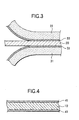
- Fig. 3 is an enlarged sectional view illustrating one embodiment of the present invention wherein a separator is bonded to the negative electrode of the present invention;
- Fig. 4 is an enlarged sectional view illustrating one embodiment of the present invention wherein a resin layer is formed on the positive electrode;
- Fig. 5 is an enlarged view illustrating one embodiment of the present invention wherein the negative electrode and the positive electrode are bonded to each other;
- Fig. 6 is a perspective view of one embodiment of the electricity-storing element and the battery container of the present invention;
- Fig. 7 is a perspective view of one embodiment of the battery of the present invention;
- Fig. 8 is an electron microphotograph of the resin layer of Example 1;
- Fig. 9 is an electron microphotograph of the resin layer of Comparative Example 2;
- Fig. 10 is a graph illustrating the relationship between the particle diameter and the initial capacity and battery resistance; and
- Fig. 11 is a graph illustrating the relationship between the specific surface area and the capacity.
-
- Preferred embodiment of the present invention will be described in further detail.
- In order to confirm the effect of the present invention, a lithium ion battery having the following specification was prepared. The electricity-storing element of this battery comprises a positive electrode, a separator, a negative electrode and a separator.
- The
positive electrode 10 comprised apositive composite 12 retained on both sides of acurrent collector 11 made of an aluminum foil having a thickness of 20 µm as shown in Fig. 1. Thepositive composite 12 was prepared by mixing 91 parts of a lithium cobalt composite oxide LiCoO2 as a positive active material, 6 parts of a poly(vinylidene fluoride) as a binder and 3 parts of acetylene black as an electrically conducting material to make a paste. The composite 12 was spread to both sides of thecurrent collector 11, dried, and then rolled to prepare thepositive electrode 10. Thepositive electrode 10 was then cut to a predetermined width. Thus, thepositive electrode 10 was then used in the form of belt. - On the other hand, as shown in Fig. 2, the
negative electrode 20 comprised a negative composite 22 retained on both sides of acurrent collector 21 made of a copper foil having a thickness of 10 µm. Thenegative composite 22 was prepared by mixing 92 parts of a graphite powder having a specific surface area of 1 m2/g as a negative active material and 8 parts of a poly(vinylidene fluoride) as a binder, and then properly adding N-methyl-2-pyrrolidone to the mixture to make a paste. The composite 22 was applied to both sides of thecurrent collector 21, dried, and then rolled to prepare thenegative electrode 20. Thenegative electrode 20 was then cut to a predetermined width, and used in the form of belt. - As the separator, a porous polyethylene sheet having a porosity of 45% was provided interposed between the electrodes. The thickness of the separator was varied from 15 to 25 µm as set forth in Table 1 shown later.
- As the resin layer, a copolymer of vinylidene fluoride and hexafluoropropylene was previously emulsion-polymerized. The emulsion of copolymer was dehydrated to a powder, which was then dissolved in N-methyl-2-pyrrolidone. To the solution was then added to an alumina powder to prepare a sticky paste. An alumina powder having a primary particle diameter of from 10 to 20 nm and a specific surface area of 100 ± 15 m2/g (the BET method) was used. The sticky paste used comprised the copolymer and the alumina powder at a mixing ratio of 1 : 1 by dry weight.
- Subsequently, as shown in Fig. 3, the mixture was applied to one side of a
separator 31 to form aresin layer 33. Two sheets of theseparator 31 having theresin layer 33 formed thereon were prepared and bonded to the respective side of thenegative electrode 20 before theresin layer 33 was dried. The bonding was carried out such that theresin layer 33 of theseparator 31 was opposed to thenegative electrode 20. - Subsequently, as shown in Fig. 4, the same mixture as mentioned above was applied to both sides of the
positive electrode 10. During this procedure, the spread amount of the mixture was adjusted such that theresin layer 41 formed on thepositive electrode 10 had the same thickness as that of theresin layer 33 formed on theseparator 31. Subsequently, as shown in Fig. 5, thenegative electrode 20 having theseparator 31 bonded to both sides thereof and thepositive electrode 10 having theresin layer 41 formed on both sides thereof were laminated and bonded to each other. The end of thecurrent collector 11 of thepositive electrode 10 is not coated with the positive composite 12, and a leaf ofaluminum lead 64 is ultrasonically welded thereto (see Fig. 6). The end of thecurrent collector 21 of thenegative electrode 20 has a region which is not coated with thenegative composite 22, and a leaf oflead 65 is ultrasonically welded thereto (see Fig. 6). - The electrodes were wound on a metallic core, and the core was then pulled out of the winding to produce an electricity-storing
element 61. Subsequently, the electricity-storingelement 61 was received in a bag-shapedcontainer 63 made of a metal-resin laminate film as shown in Fig. 6. Thecontainer 63 is made of a metal-resin laminate film having a three-layer structure comprising a surface protective layer made of PET (poly(ethylene terephthalate)), a barrier layer made of aluminum and a weld layer made of PE (polyethylene). The metal-resin laminate film is folded with the weld layer inside, and then welded at the bottom and sides thereof to form a bag. Finally, the bag is welded at the upper opening thereof. - Subsequently, an electrolyte was injected into the
container 63 which had the electricity-storingelement 61 received therein. The electrolyte is a 1 : 1 (by volume) mixture of ethylene carbonate and diethyl carbonate containing 1 mol/l of LiPF6. Thus, a 650 mAhlithium ion battery 70 having an average discharge voltage of 3.7 V and a size of 3.8 mm (thickness) x 35 mm (width) x 62 mm (length) was obtained. - Batteries of Examples 1 to 6 were prepared from different combinations of the thickness D of separator and the thickness J of resin layer as set forth in Table 1. As Comparative Example 1, a battery free of resin layer was prepared. As Comparative Example 2, a battery comprising a resin layer but free of alumina powder therein was prepared. The batteries of Examples 1 to 6 and Comparative Examples 1 and 2 were each subjected to charge and discharge cycles, and then measured for the capacity change. The results are set forth in Table 1. Referring to the charge and discharge cycle conditions, one cycle consists of 3 hours of charging at a constant voltage of 4.2 V and discharging to 2.75 V with a constant current of 1 CA (650 mA). The capacity in Table 1 is represented relative to the discharge capacity of 650 mA of the battery of Example 3 which has been charged for the first time as 100.

- As can be seen in Table 1, all the batteries of Examples 1 to 6 exhibited a high initial capacity and maintained a high capacity even after 200 cycles. The batteries of Examples 1 to 4 and Example 6 still maintained a high capacity after 300 cycles.
- On the contrary, the battery of Comparative Example 1, which is free of resin layer, showed an initial capacity but showed a capacity drop every repetition of charge and discharge cycle and then showed an extremely low capacity after 200 cycles. Thus, the batteries of Examples 1 to 6 have electrodes and a separator bonded to each other with a porous resin layer and can keep the distance between the electrodes constant even if the battery container is so flexible that the pressure from the battery container is not sufficient. These batteries were confirmed to undergo no capacity drop even after repeated charge and discharge and exhibit a prolonged life.
- The battery of Comparative Example 2, which comprises no alumina powder incorporated in the resin layer, exhibited an extremely low initial capacity.
- Subsequently, the
resin layer 41 formed between thepositive electrode 10 and theseparator 31 and theresin layer 33 formed between thenegative electrode 20 and theseparator 31 in the battery of Example 1 were observed under electron microscope. Fig. 8 illustrates an electron microphotograph of theresin layer 41 formed between thepositive electrode 10 and theseparator 31. The resin layer was confirmed porous as shown in Fig. 8. Though not shown, theresin layer 33 formed between thenegative electrode 20 and theseparator 31 was similarly confirmed porous. - Fig. 9 illustrates an electron microphotograph of the resin layer free of alumina powder formed in the battery of Comparative Example 2. The resin layer in the battery of Comparative Example 2 was confirmed non-porous. It was thus confirmed that a resin layer filled with an alumina powder as a solid filler is rendered porous. Accordingly, it was confirmed that the batteries of Examples 1 to 6 exhibit a higher energy density than the battery of Comparative Example 2 and a high initial capacity.
- The effect of the average particle diameter of solid filler on the initial capacity was then studied. In this test, batteries having the same structure as that of Example 1 except that the average particle diameter of the alumina powder were varied were prepared (see Table 2). In other words, the thickness of the separator was 20 µm and the thickness of the resin layer was 1.5 µm.
- These batteries were each subjected to charge and discharge cycle, and then measured for initial capacity. The results are set forth in Table 2. Referring to the charge and discharging cycle conditions, one cycle consists of 3 hours of charging at a constant voltage of 4.2 V and discharging to 2.75 V with a constant current of 1 CA (650 mA). In Table 2, the initial capacity is represented relative to that of the battery of Comparative Example 1 as 100, and the electrical resistance is represented relative to that of the battery of Comparative Example 1 as 100.
- As shown in Table 2 and Fig. 10, the batteries comprising an alumina powder having an average particle diameter of from 5 to 100 nm exhibit a higher initial capacity and a lower resistance than that of Comparative Example 1 which is free of resin layer.
Average particle diameter (nm) Initial capacity (%) Battery resistance (%) 0 42.5 145 3 77.3 127 5 100.3 103 10 101.8 100 50 102.0 100 100 101.3 105 150 97.0 118 - The effects of the specific surface area of the solid filler on the initial capacity and cycle life performance were then studied. In this test, batteries having the same structure as that of Example 1 except that the specific surface area of alumina powder was varied were prepared (see Table 3). In other words, the thickness of the separator was 20 µm and the thickness of the resin layer was 1.5 µm.
- These batteries were each subjected to charge and discharge cycles, and then measured for initial capacity and capacity after 100 cycles. The results are set forth in Table 3. Referring to the charge and discharge cycle conditions, one cycle consists of 3 hours of charging at a constant voltage of 4.2 V and discharging to 2.75 V with a constant current of 1 CA (650 mA). In Table 3, the initial capacity and capacity after 100 cycles are represented relative to that of the battery of Comparative Example 1 as 100, and the electrical resistance is represented relative to that of the battery of Comparative Example 1 as 100.
- As shown in Table 3 and Fig. 11, the batteries comprising an alumina powder having a specific surface area of from not smaller than 50 m2/g to not greater than 500 m2/g exhibit a higher initial capacity and a longer life than that of Comparative Example 1 which is free of resin layer.
Specific surface area (m2/g) Initial capacity (%) Capacity at 100th cycle (%) 28 72.9 66.2 55 100.8 95.8 108 101.8 96.9 480 100.9 94.8 770 100.2 81.2 - As mentioned above, the present invention can provide a battery having a high energy density and an excellent cycle life performance, even when the electricity-storing element is received in a case made of a flexible material.
Claims (11)
- A batttery comprising a positive electrode, a negative electrode and a separator provided interposed therebetween, wherein at least one surface of said separator is bonded to said positive electrode or negative electrode via a porous resin layer comprising a solid filler.
- The battery as defined in Claim 1, wherein the thickness of said resin layer is from 1 µm to 10 µm.
- The battery as defined in Claim 1 or 2, wherein the thickness of said separator is not greater than 25 µm.
- The battery as defined in Claims 1, 2 and 3, wherein said resin layer comprises at least one member selected from the group consisting of polyethylene, polypropylene, poly(vinylidene chloride), poly(vinylidene fluoride), polyethylene oxide and polyacrylonitrile.
- The battery as defined in Claims 1, 2 and 3, wherein said resin layer comprises at least one member selected from the group consisting of copolymer of vinylidene fluoride and hexafluoropropylene, copolymer of vinylidene fluoride and chlorotrifluoroethylene, copolymer of vinylidene fluoride, hexafluoropropylene and tetrafluoroethylene, copolymer of vinylidene fluoride and tetrafluoroethylene and copolymer of hexafluoropropylene and tetrafluoroethylene.
- The battery as defined in any one of Claim 1 to 5, wherein and solid filler comprises a ceramic powder comprising primary particles having an average diameter of from 5 nm to 100 nm.
- The battery as defined in Claim 6, wherein said ceramic powder comprises at least one member selected from the group consisting of alumina, silica, titania and zirconia.
- The battery as defined in Claim 6, wherein the specific surface area of said solid filler is from not smaller than 50 m2/g to not greater than 500 m2/g.
- The battery as defined in any one of Claims 1 to 8, wherein said positive electrode, said negative electrode, said separator and said resin layer are at least partly impregnated with a non-aqueous electrolyte.
- The battery as defined in any one of Claims 1 to 9, wherein a part of said resin layer penetrates into the surface layer of said positive electrode and said negative electrode.
- The battery as defined in any one of Claims 1 to 10, wherein said positive electrode, said negative electrode and said separator are received in a flexible material case.
Applications Claiming Priority (5)
| Application Number | Priority Date | Filing Date | Title |
|---|---|---|---|
| JP2000169869 | 2000-06-07 | ||
| JP2000169869 | 2000-06-07 | ||
| JP2000204857 | 2000-07-06 | ||
| JP2000204857 | 2000-07-06 | ||
| PCT/JP2001/004652 WO2001095421A1 (en) | 2000-06-07 | 2001-06-01 | Battery |
Publications (1)
| Publication Number | Publication Date |
|---|---|
| EP1291952A1 true EP1291952A1 (en) | 2003-03-12 |
Family
ID=26593450
Family Applications (1)
| Application Number | Title | Priority Date | Filing Date |
|---|---|---|---|
| EP01934497A Withdrawn EP1291952A1 (en) | 2000-06-07 | 2001-06-01 | Battery |
Country Status (7)
| Country | Link |
|---|---|
| US (1) | US6773847B2 (en) |
| EP (1) | EP1291952A1 (en) |
| JP (1) | JP5073144B2 (en) |
| KR (1) | KR100789558B1 (en) |
| CN (1) | CN1193448C (en) |
| TW (1) | TW508856B (en) |
| WO (1) | WO2001095421A1 (en) |
Cited By (2)
| Publication number | Priority date | Publication date | Assignee | Title |
|---|---|---|---|---|
| WO2005098997A1 (en) | 2004-03-30 | 2005-10-20 | Matsushita Electric Industrial Co., Ltd. | Nonaqueous electrolyte secondary battery |
| EP1667255A4 (en) * | 2003-09-18 | 2009-11-11 | Panasonic Corp | LITHIUM-ION BATTERY |
Families Citing this family (28)
| Publication number | Priority date | Publication date | Assignee | Title |
|---|---|---|---|---|
| JP4423699B2 (en) | 1999-05-27 | 2010-03-03 | ソニー株式会社 | Semiconductor laser device and manufacturing method thereof |
| US6677076B2 (en) | 2002-01-15 | 2004-01-13 | Quallion Llc | Electric storage battery construction and method of manufacture |
| US6670071B2 (en) | 2002-01-15 | 2003-12-30 | Quallion Llc | Electric storage battery construction and method of manufacture |
| DE10255122A1 (en) * | 2002-11-26 | 2004-06-03 | Creavis Gesellschaft Für Technologie Und Innovation Mbh | Long-term stable separator for an electrochemical cell |
| US20040166415A1 (en) | 2003-02-21 | 2004-08-26 | Celgard Inc. | Oxidation resistant separator for a battery |
| JP4140517B2 (en) * | 2003-12-12 | 2008-08-27 | 松下電器産業株式会社 | Lithium ion secondary battery and its construction method |
| JP3953026B2 (en) * | 2003-12-12 | 2007-08-01 | 松下電器産業株式会社 | Electrode plate for lithium ion secondary battery, lithium ion secondary battery and method for producing the same |
| US8080329B1 (en) | 2004-03-25 | 2011-12-20 | Quallion Llc | Uniformly wound battery |
| CN100394632C (en) * | 2004-03-30 | 2008-06-11 | 松下电器产业株式会社 | Non-aqueous electrolyte secondary battery |
| JP4649862B2 (en) * | 2004-04-02 | 2011-03-16 | パナソニック株式会社 | Lithium ion secondary battery and manufacturing method thereof |
| JP4774941B2 (en) | 2005-11-14 | 2011-09-21 | ソニー株式会社 | Gel electrolyte and gel electrolyte battery |
| JP2007220454A (en) * | 2006-02-16 | 2007-08-30 | Matsushita Electric Ind Co Ltd | Nonaqueous electrolyte secondary battery |
| CN101809801B (en) * | 2007-09-28 | 2014-03-26 | A123系统公司 | Batteries with inorganic/organic porous membranes |
| KR100983161B1 (en) | 2008-01-11 | 2010-09-20 | 삼성에스디아이 주식회사 | Electrode assembly and secondary battery having same |
| CN101499538B (en) * | 2008-02-01 | 2012-07-11 | 索尼株式会社 | Non-aqueous electrolyte cell, anode and manufacturing method of the same |
| DE102008043960A1 (en) * | 2008-11-21 | 2010-05-27 | Robert Bosch Gmbh | Device with at least one accumulator cell |
| US8790419B2 (en) * | 2009-05-08 | 2014-07-29 | Toyota Jidosha Kabushiki Kaisha | Cell separator comprising protective layer manufacturing method |
| KR20120022722A (en) * | 2010-04-27 | 2012-03-12 | 파나소닉 주식회사 | Non-aqueous secondary battery and electrode assembly used therefor |
| JP2013143336A (en) * | 2012-01-12 | 2013-07-22 | Nissan Motor Co Ltd | Manufacturing method of packed electrode, packed electrode, secondary battery, and heat sealing device |
| JP6105226B2 (en) * | 2012-08-09 | 2017-03-29 | 三洋電機株式会社 | Nonaqueous electrolyte secondary battery |
| CN105794018B (en) * | 2013-09-02 | 2020-07-17 | 日本戈尔有限公司 | Protective film, spacer using the same, and rechargeable battery |
| CN103956447B (en) * | 2014-04-23 | 2016-10-05 | 明基材料有限公司 | A kind of porous isolating membrane and manufacture method thereof |
| JP6415312B2 (en) * | 2014-12-26 | 2018-10-31 | 積水化学工業株式会社 | Separator and electrochemical device |
| CN105514328A (en) * | 2016-01-13 | 2016-04-20 | 浙江天能能源科技有限公司 | Ceramic diaphragm for lithium ion battery and preparation method of ceramic diaphragm |
| EP3522289B1 (en) | 2016-09-27 | 2022-12-21 | GS Yuasa International Ltd. | Separator having heat resistant layer for power storage element and method for manufacturing same |
| JP7032180B2 (en) * | 2018-03-07 | 2022-03-08 | トヨタ自動車株式会社 | Batteries and their manufacturing methods |
| CN114497833A (en) * | 2020-11-11 | 2022-05-13 | 华为技术有限公司 | Battery packaging film, preparation method of battery packaging film and electronic equipment |
| JP7202407B2 (en) * | 2021-02-22 | 2023-01-11 | プライムプラネットエナジー&ソリューションズ株式会社 | secondary battery |
Family Cites Families (14)
| Publication number | Priority date | Publication date | Assignee | Title |
|---|---|---|---|---|
| JPH04225367A (en) * | 1990-12-27 | 1992-08-14 | Fujitsu Ltd | Nonmagnetic one component developing method |
| CA2226366C (en) * | 1995-08-28 | 2002-05-21 | Asahi Kasei Kogyo Kabushiki Kaisha | Novel battery and method for producing the same |
| US5948464A (en) | 1996-06-19 | 1999-09-07 | Imra America, Inc. | Process of manufacturing porous separator for electrochemical power supply |
| JP3303694B2 (en) | 1996-12-17 | 2002-07-22 | 三菱電機株式会社 | Lithium ion secondary battery and method of manufacturing the same |
| JPH11315472A (en) * | 1997-11-11 | 1999-11-16 | Nippon Sheet Glass Co Ltd | Nonwoven fabric, method for producing the same, and alkaline secondary battery using the same |
| EP0954042B1 (en) * | 1997-11-19 | 2007-09-05 | Mitsubishi Denki Kabushiki Kaisha | Lithium ion secondary battery and manufacture thereof |
| ES2172907T3 (en) * | 1998-06-23 | 2002-10-01 | Daramic Inc | SEPARATOR FOR CLOSED LEAD ACCUMULATORS. |
| JP3471238B2 (en) * | 1998-08-31 | 2003-12-02 | 株式会社東芝 | Manufacturing method of non-aqueous electrolyte secondary battery |
| JP2000106167A (en) * | 1998-09-30 | 2000-04-11 | Mitsubishi Electric Corp | Battery |
| JP4392881B2 (en) * | 1998-11-04 | 2010-01-06 | アオイ電子株式会社 | Lithium secondary battery |
| US6537703B2 (en) * | 1998-11-12 | 2003-03-25 | Valence Technology, Inc. | Polymeric mesoporous separator elements for laminated lithium-ion rechargeable batteries |
| US6194098B1 (en) * | 1998-12-17 | 2001-02-27 | Moltech Corporation | Protective coating for separators for electrochemical cells |
| AU5731400A (en) * | 1999-06-09 | 2000-12-28 | Moltech Corporation | Methods of preparing electrochemical cells |
| JP2001006743A (en) | 1999-06-23 | 2001-01-12 | Japan Storage Battery Co Ltd | Battery |
-
2001
- 2001-06-01 EP EP01934497A patent/EP1291952A1/en not_active Withdrawn
- 2001-06-01 KR KR1020027001618A patent/KR100789558B1/en not_active Expired - Lifetime
- 2001-06-01 CN CNB018016340A patent/CN1193448C/en not_active Expired - Lifetime
- 2001-06-01 JP JP2002502855A patent/JP5073144B2/en not_active Expired - Lifetime
- 2001-06-01 WO PCT/JP2001/004652 patent/WO2001095421A1/en not_active Ceased
- 2001-06-01 US US10/049,041 patent/US6773847B2/en not_active Expired - Lifetime
- 2001-06-05 TW TW090113600A patent/TW508856B/en active
Non-Patent Citations (1)
| Title |
|---|
| See references of WO0195421A1 * |
Cited By (4)
| Publication number | Priority date | Publication date | Assignee | Title |
|---|---|---|---|---|
| EP1667255A4 (en) * | 2003-09-18 | 2009-11-11 | Panasonic Corp | LITHIUM-ION BATTERY |
| US8211574B2 (en) | 2003-09-18 | 2012-07-03 | Panasonic Corporation | Lithium ion secondary battery |
| WO2005098997A1 (en) | 2004-03-30 | 2005-10-20 | Matsushita Electric Industrial Co., Ltd. | Nonaqueous electrolyte secondary battery |
| EP1659650A4 (en) * | 2004-03-30 | 2008-12-24 | Panasonic Corp | NONAQUEOUS ELECTROLYTE SECONDARY BATTERY |
Also Published As
| Publication number | Publication date |
|---|---|
| TW508856B (en) | 2002-11-01 |
| US6773847B2 (en) | 2004-08-10 |
| KR100789558B1 (en) | 2007-12-28 |
| JP5073144B2 (en) | 2012-11-14 |
| KR20020019608A (en) | 2002-03-12 |
| CN1193448C (en) | 2005-03-16 |
| WO2001095421A1 (en) | 2001-12-13 |
| CN1383588A (en) | 2002-12-04 |
| US20020146626A1 (en) | 2002-10-10 |
Similar Documents
| Publication | Publication Date | Title |
|---|---|---|
| US6773847B2 (en) | Battery | |
| KR101766871B1 (en) | Electrode for a secondary battery, preparation method thereof, secondary battery and cable-type secondary battery including the same | |
| US8076023B2 (en) | Non-aqueous electrolyte secondary battery and battery module | |
| KR100573722B1 (en) | Granular Electrode with Electrolyte for Rechargeable Lithium Battery | |
| EP0971430B1 (en) | Secondary battery with adhesive resin layer structure | |
| JPWO2001095421A1 (en) | Battery | |
| US6617074B1 (en) | Lithium ion polymer secondary battery and gelatinous polymer electrolyte for sheet battery | |
| CN110546804B (en) | Non-aqueous electrolyte secondary battery | |
| EP1386363B1 (en) | Structure and methods of fabricating binding layers for a li-ion polymer battery | |
| CN107666009A (en) | Hybrid battery design with alternately stacked or wound Li-ion battery packs and capacitor electrodes | |
| KR20180077189A (en) | Separator for non-aqueous secondary battery and non-aqueous secondary battery | |
| US8785047B2 (en) | Lithium-ion secondary battery and method of charging lithium-ion secondary battery | |
| JP7729638B2 (en) | electrode assembly | |
| US10826039B2 (en) | Electrode assembly including electrode and separator partially bonded to each other | |
| EP3073556B1 (en) | Energy storage device | |
| JP2000251944A (en) | Non-aqueous electrolyte secondary battery and method of manufacturing non-aqueous electrolyte secondary battery | |
| JP7779090B2 (en) | Negative electrode for secondary battery and method for manufacturing same | |
| JP7108052B2 (en) | Storage element and method for manufacturing storage element | |
| JP2000268873A (en) | Lithium secondary battery and battery device using the same | |
| JPH10241656A (en) | Battery | |
| JP2001084985A (en) | Rechargeable battery | |
| EP3389121B1 (en) | Energy storage device | |
| EP0969542B1 (en) | Battery | |
| KR20180032763A (en) | Electrode Assembly Applied with Partially Binding between Electrode and Separator | |
| JP6989322B2 (en) | Positive electrode for lithium-ion secondary battery |
Legal Events
| Date | Code | Title | Description |
|---|---|---|---|
| PUAI | Public reference made under article 153(3) epc to a published international application that has entered the european phase |
Free format text: ORIGINAL CODE: 0009012 |
|
| 17P | Request for examination filed |
Effective date: 20020206 |
|
| AK | Designated contracting states |
Kind code of ref document: A1 Designated state(s): AT BE CH CY DE DK ES FI FR GB GR IE IT LI LU MC NL PT SE TR Designated state(s): AT BE CH CY DE DK ES FI FR GB GR IE IT LI LU MC NL PT SE TR |
|
| AX | Request for extension of the european patent |
Extension state: AL LT LV MK RO SI |
|
| RBV | Designated contracting states (corrected) |
Designated state(s): DE FR GB |
|
| RAP1 | Party data changed (applicant data changed or rights of an application transferred) |
Owner name: SANYO GS SOFT ENERGY CO., LTD. |
|
| STAA | Information on the status of an ep patent application or granted ep patent |
Free format text: STATUS: THE APPLICATION HAS BEEN WITHDRAWN |
|
| 18W | Application withdrawn |
Effective date: 20060309 |