Technical Field
-
This invention relates to a fuel cell. More particularly, it relates to a fuel cell
in which plural unit fuel cells as units are internally connected together to generate
desired electromotive force as well as to reduce the size or thickness of the cell.
Background Art
-
Up to now, fossil fuels, such as gasoline or light oil, have been used extensively
not only as an energy source for automobiles, but also as an energy source for power
generation. Through the use of these fossil fuels, the mankind could enjoy such
benefits as drastically improved life level or industrial development. On the other
hand, the earth is imperiled by a serious risk of environmental destruction. Moreover,
the resources of fossil fuel tend to be depleted such that difficulties are feared to be
met as to stable supply of fossil fuel over a long term.
-
Hydrogen is attracting attention as an energy source which is to take the place
of the fossil fuel. Hydrogen is contained in water and exists abundantly on the earth,
while a large amount of chemical energy is contained per unit weight therein.
Moreover, when used as an energy source, hydrogen does not yield obnoxious
materials or gases tending to produce global warming. For these reasons, hydrogen
is attracting significant attention as being an energy source which is to take the place
of the fossil fuel and which is clean and plentiful in supply.
-
Recently, studies and developments in the fuel cell, capable of taking an
electrical energy from the hydrogen energy, are going on briskly, such that
expectations are made for application of the fuel cell to large-scale power generation
or on-site self-generation, or as a power source for automobiles.
-
A fuel cell for taking the electrical energy from the hydrogen energy includes
a hydrogen electrode fed with a hydrogen gas and an oxygen electrode fed with
oxygen. A hydrogen gas fed to the hydrogen electrode is dissociated by catalyst action
into protons and electrons. The electrons are absorbed by a hydrogen electrode,
whilst the protons are transported to the oxygen electrode. The electrons absorbed in
the oxygen electrode are migrated through a load to the oxygen electrode. On the
other hand, oxygen fed to the oxygen electrode is combined by the catalyst action with
the protons and electrons migrated from the hydrogen electrode to yield water. Thus,
a unit fuel cell is constructed so that an electromotive force is generated between the
hydrogen electrode and the oxygen electrode to cause the current to flow through the
load.
-
Such fuel cell is preferably so constructed that a plural number of such unit fuel
cells are internally connected in a desired manner to generate desired electromitive
foce. If special interconnections are used for internally connecting a plural number of
the unit fuel cells, there is raised a problem that difficulties are met in reducing the size
or the thickness of fuel cell.
Disclosure of the Invention
-
It is an object of the present invention to provide a novel fuel cell capable of
overcoming the aforementioned problems inherent in the prior art.
-
It is another object of the present invention to provide a fuel cell formed by
internally connecting a plural number of unit fuel cells together to generate desired
electromotive force as well as to enable the size or the thickness of the cell to be
reduced.
-
For accomplishing the above object, the present invention provides a fuel cell
including at least one unit fuel cell including a hydrogen gas path forming plate having
a plurality of openings, an oxygen electrode plate having a proton conductor film and
a plurality of openings, and an air flow path forming plate having a plurality of
openings, with the hydrogen gas path forming plate, oxygen electrode plate and the air
flow path forming plate layered together in this order, at least two selectively
disconnectable connection pins being formed on a peripheral portion of the hydrogen
electrode plate and on a peripheral portion of the oxygen electrode plate.
-
In the fuel cell of the present invention, at least two selectively rupturable
connection pins are formed on the peripheral portions of the hydrogen electrode plate
and the oxygen electrode plate making up the unit fuel cell, so that, by selectively
rupturing or leaving at least two connection pins, similarly selectively rupturing or
leaving at least two connection pins formed on the peripheral portions of the hydrogen
electrode plate and the oxygen electrode plate making up another unit fuel cell, and
by abutting the connection pins, left intact, against one another, a fuel cell may be
obtained having two or more unit fuel cells connected internally to one another.
-
The proton conductor film forming the fuel cell according to the present
invention contains a proton conductor containing, as a main component, a fullerene
derivative having a group capable of dissociating protons introduced into carbon atoms
making up the fullerene molecules.
-
Preferably, the group capable of dissociating protons is composed of -XH,
where X is an optional atom or a group of atoms having divalent bonds.
-
More preferably, the group capable of dissociating protons is a group selected
from the group consisting of-OH or -YH, where Y is an optional atom or a group of
atoms having divalent bonds.
-
More preferably, the group capable of dissociating protons is selected from the
group consisting of -OH, -SO3H4, -COOH, -SO3H and -OPO(OH)3.
-
The fullerene derivative is composed of polyfullerene hydroxide (fullerenol).
-
The proton conductor contains electrophilic groups introduced into carbon
atoms making up the fullerene molecules, in addition to the groups capable of
dissociating protons.
-
The electrophilic groups may include a nitro group, a carbonyl group, a
carboxylic group, a nitrile group, a halogrenated alkyl group or a group containing
halogen atoms.
-
The proton conductor film used in the present invention may include a proton
conductor composed of perfluorosulfonic acid resin (Nafion manufactured by Du Pont
of USA (registered trademark)).
-
According to the present invention, the fullerene molecules mean spherically-shaped
carbon cluster molecules having 30, 60, 70, 78, 82 or 84 carbon atoms.
-
In the fuel cell of the present invention, the hydrogen electrode plate and the
oxygen electrode plate are substantially rectangular in profile, with the interconnection
pins being formed on at least one side of each of the hydrogen electrode plate and the
oxygen electrode plate. More preferably, the hydrogen electrode plate and the oxygen
electrode plate are substantially rectangular in profile, with the interconnection pins
being formed on the four sides of the hydrogen electrode plate and the oxygen
electrode plate.
-
With the above-described structure of the fuel cell of the present invention, a
fuel cell may be provided in which the unit fuel cells are internally connected with a
larger number of the degrees of freedom.
-
In a further fuel cell according the present invention, at least two
interconnection pins formed on the peripheral portion of the hydrogen electrode plate
and at least two interconnection pins formed on the peripheral portion of the oxygen
electrode plate are formed in a case in which two of the unit fuel cells are apposed
together, the at least two interconnection pins formed on the peripheral portion of the
hydrogen electrode plate and on the peripheral portion of the oxygen electrode plate
are severed selectively, so that the at least two interconnection pins formed on the
peripheral portion of the hydrogen electrode plate of one of the unit fuel cells and the
at least two interconnection pins formed on the peripheral portion of the hydrogen
electrode plate of the other one of the unit fuel cells are connected electrically and the
at least two interconnection pins formed on the peripheral portion of the oxygen
electrode plate of one of the unit fuel cells and the at least two interconnection pins
formed on the peripheral portion of the oxygen electrode plate of the other one of the
unit fuel cells are connected electrically.
-
In the fuel cell according the present invention, the at least two interconnection
pins formed on the peripheral portion of the hydrogen electrode plate and at least two
interconnection pins formed on the peripheral portion of the oxygen electrode plate are
formed in a case in which two of the unit fuel cells are apposed together, the at least
two interconnection pins formed on the peripheral portion of the hydrogen electrode
plate and on the peripheral portion of the oxygen electrode plate are severed
selectively, so that the at least two interconnection pins formed on the peripheral
portion of the hydrogen electrode plate of one of the unit fuel cells and the at least two
interconnection pins formed on the peripheral portion of the hydrogen electrode plate
of the other one of the unit fuel cells are connected electrically and the at least two
interconnection pins formed on the peripheral portion of the oxygen electrode plate of
one of the unit fuel cells and the at least two interconnection pins formed on the
peripheral portion of the oxygen electrode plate of the other one of the unit fuel cells
are connected electrically. So, two unit fuel cells can be connected in parallel with
each other, without employing any special wiring, measly on selectively rupturing at
least two interconnection pins formed on the peripheral portions of the hydrogen
electrode plate and the oxygen electrode plate making up each of the unit fuel cells
juxtaposed to each other.
-
These at least two interconnection pins, formed on the peripheral portion of the
hydrogen electrode plate and the oxygen electrode plate, may be selectively rupturable
while being selectively bendable.
-
In a further fuel cell according to the present invention, at least two
interconnection pins formed on the peripheral portion of the hydrogen electrode plate
and at least two interconnection pins formed on the peripheral portion of the oxygen
electrode plate are formed in a case in which two of the unit fuel cells are apposed
together, the at least two interconnection pins formed on the peripheral portion of the
hydrogen electrode plate and on the peripheral portion of the oxygen electrode plate
are severed or bent selectively, so that the at least two interconnection pins formed on
the peripheral portion of the hydrogen electrode plate of one of the unit fuel cells and
the at least two interconnection pins formed on the peripheral portion of the hydrogen
electrode plate of the other one of the unit fuel cells are connected electrically and the
at least two interconnection pins formed on the peripheral portion of the oxygen
electrode plate of one of the unit fuel cells and the at least two interconnection pins
formed on the peripheral portion of the oxygen electrode plate of the other one of the
unit fuel cells are connected electrically.
-
In the fuel cell according to the present invention, at least two interconnection
pins formed on the peripheral portion of the hydrogen electrode plate and at least two
interconnection pins formed on the peripheral portion of the oxygen electrode plate are
formed in a case in which two of the unit fuel cells are apposed together, the at least
two interconnection pins formed on the peripheral portion of the hydrogen electrode
plate and on the peripheral portion of the oxygen electrode plate are severed or bent
selectively, so that the at least two interconnection pins formed on the peripheral
portion of the hydrogen electrode plate of one of the unit fuel cells and the at least two
interconnection pins formed on the peripheral portion of the hydrogen electrode plate
of the other one of the unit fuel cells are connected electrically and the at least two
interconnection pins formed on the peripheral portion of the oxygen electrode plate of
one of the unit fuel cells and the at least two interconnection pins formed on the
peripheral portion of the oxygen electrode plate of the other one of the unit fuel cells
are connected electrically. So, two unit fuel cells can be connected in parallel with
each other, in desired manner, without employing any special wiring, measly on
selectively rupturing or bending at least two interconnection pins formed on the
peripheral portions of the hydrogen electrode plate and the oxygen electrode plate
making up each of the unit fuel cells juxtaposed to each other.
-
In a further fuel cell according to the present invention, at least two
interconnection pins formed on the peripheral portion of the hydrogen electrode plate
and at least two interconnection pins formed on the peripheral portion of the oxygen
electrode plate are formed in a case in which two of the unit fuel cells are stacked
together with the hydrogen gas flow path forming plate in common, the at least two
interconnection pins formed on the peripheral portion of the hydrogen electrode plate
and on the peripheral portion of the oxygen electrode plate are bent selectively, so that
the at least two interconnection pins formed on the peripheral portion of the hydrogen
electrode plate of one of the unit fuel cells and the at least two interconnection pins
formed on the peripheral portion of the hydrogen electrode plate of the other one of
the unit fuel cells are connected electrically and the at least two interconnection pins
formed on the peripheral portion of the oxygen electrode plate of one of the unit fuel
cells and the at least two interconnection pins formed on the peripheral portion of the
oxygen electrode plate of the other one of the unit fuel cells are connected electrically.
-
In the fuel cell of the present invention, the at least two interconnection pins
formed on the peripheral portion of the hydrogen electrode plate and at least two
interconnection pins formed on the peripheral portion of the oxygen electrode plate are
formed in a case in which two of the unit fuel cells are stacked together with the
hydrogen gas flow path forming plate in common, the at least two interconnection pins
formed on the peripheral portion of the hydrogen electrode plate and on the peripheral
portion of the oxygen electrode plate are bent selectively, so that the at least two
interconnection pins formed on the peripheral portion of the hydrogen electrode plate
of one of the unit fuel cells and the at least two interconnection pins formed on the
peripheral portion of the hydrogen electrode plate of the other one of the unit fuel cells
are connected electrically and the at least two interconnection pins formed on the
peripheral portion of the oxygen electrode plate of one of the unit fuel cells and the at
least two interconnection pins formed on the peripheral portion of the oxygen
electrode plate of the other one of the unit fuel cells are connected electrically. So,
two unit fuel cells can be connected in parallel with each other, in desired manner,
without employing any special wiring, measly on selectively bending at least two
interconnection pins formed on the peripheral portions of the hydrogen electrode plate
and the oxygen electrode plate making up each of the unit fuel cells juxtaposed to each
other.
-
The fuel cell according to the present invention may also include a module
retention plate having a plurality of openings, the module retention plate being
provided on the opposite side of the air flow path forming plate forming the unit fuel
cell with respect to the oxygen electrode plate.
-
In the fuel cell according to the present invention, the hydrogen gas flow path
forming plate may be of a thickness of 0.01 mm to 1 mm, the hydrogen electrode plate
may be of a thickness of 0.01 mm to 1 mm, the air flow path forming plate may be of
a thickness of 0.01 mm to 0.5 mm and the oxygen electrode plate may be of a
thickness of 0.01 mm to 1 mm.
-
The hydrogen gas flow path forming plate may be formed of a material
selected from the group consisting of polycarbonate, acrylic resin, ceramics, carbon,
hastelloy, stainless steel, nickel, molybdenum, copper, aluminum, iron, silver, gold,
platinum, tantalum and titanium.
-
The hydrogen electrode plate may be formed of a material selected from the
group consisting of hastelloy, stainless steel, nickel, molybdenum, copper, aluminum,
iron, silver, gold, platinum, tantalum and titanium and alloys of two or more of the
materials.
-
The air flow path forming plate is plate may be formed of a material selected
from the group consisting of polycarbonate, acrylic resin, ceramics, carbon, hastelloy,
stainless steel, nickel, molybdenum, copper, aluminum, iron, silver, gold, platinum,
tantalum and titanium.
-
The oxygen electrode plate may be formed of a material selected from the group
consisting of hastelloy, stainless steel, nickel, molybdenum, copper, aluminum, iron,
silver, gold, platinum, tantalum and titanium and alloys of two or more of the
materials.
-
Other objects, features and advantages of the present invention will become
more apparent from reading the embodiments of the present invention as shown in the
drawings.
Brief Description of the Drawings
-
- Fig.1 is a plan view showing a hydrogen electrode plate of a unit fuel cell
constituting a fuel cell according to the present invention.
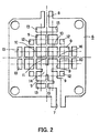
- Fig.2 is a plan view showing a hydrogen gas flow path forming plate unit fuel
cell constituting a fuel cell according to the present invention.
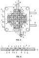
- Fig.3 is a plan view of a layered product on laminating the hydrogen gas flow
path forming plate on the hydrogen electrode plate.
- Fig.4 is a cross-sectional view taken along line IV to IV of Fig.3.
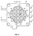
- Fig.5 is a plan view showing an oxygen electrode plate of the unit fuel cell
constituting a fuel cell according to the present invention.
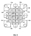
- Fig.6 is a plan view showing an air flow path forming plate unit fuel cell
constituting a fuel cell according to the present invention.
- Fig.7 is a bottom plan view of a layered product on laminating the oxygen gas
flow path forming plate on the hydrogen electrode plate.
- Fig.8 is a plan view showing a module retention plate of the unit fuel cell
constituting a fuel cell according to the present invention.
- Fig.9 is a plan view showing a layered product formed on tightly bonding the
module retention plate to the air flow path forming plate.
- Fig.10 is a cross-sectional view taken along line X-X of Fig.9.
- Fig.11 is a schematic cross-sectional view showing the state of communication
between an opening formed in the hydrogen gas flow path forming plate and an
opening formed in the hydrogen electrode plate and the state of communication
between an opening formed in the oxygen electrode plate and an opening formed in
the air flow path forming plate in the fuel cell according to the present invention.
- Fig.12 is a cross-sectional view showing another embodiment of the fuel cell
according to the present invention and showing the state of communication between
openings formed in respective components making up the fuel cell.
- Fig.13 is a side view showing a further embodiment of the fuel cell according
to the present invention.
- Fig. 14 is a plan view showing the further embodiment of the fuel cell according
to the present invention.
-
Best Mode for Carrying out the Invention
-
Referring to the drawings, preferred embodiments of the present invention are
explained in detail.
-
A hydrogen electrode plate 1 of the unit fuel cell, forming the fuel cell
according to the present invention, is formed by a substantially square-shaped plate
member formed of a stainless steel. The thickness of a plate member forming the
hydrogen electrode plate 1 is set to 0.01 mm to 1.0 mm.
-
Referring to Fig.1, the hydrogen electrode plate 1 is formed by a lattice 4 having
a regular array of 13 square-shaped openings 2 and eight triangular openings 3. The
eight triangular openings 3 are arranged on the periphery, whereas, of the 13 square-shaped
openings 2, the central opening 2 is formed in coincidence with the center P1
of the hydrogen electrode plate 1.
-
In Fig.1, A to H are pins for connection across the electrodes, and are formed
each to an elongated rectangular shape.
-
A hydrogen gas flow path forming plate 6 of the unit fuel cell constituting the
fuel cell according to the present invention is formed by a substantially square-shaped
plate member formed of polycarbonate. In the present embodiment, the thickness of
the plate member forming the hydrogen gas flow path forming plate 6 is set to 0.1 mm
to 1.0 mm. However, the plate member having a thickness of 0.1 mm to 1.0 mm may
be used for forming the hydrogen gas flow path forming plate 6.
-
In one end of the hydrogen gas flow path forming plate 6 is formed a first cut-out
7 forming a hydrogen gas supplying unit, whereas, in the opposite end thereof, a
second cut-out 8 forming a hydrogen gas ejection unit is formed, as shown in Fig.2.
In the hydrogen gas flow path forming plate 6, there are formed 12 square-shaped
openings 8 to the same size by a lattice 10. Of the 12 square-shaped openings 9, the
square-shaped opening 9 communicating with the first cut-out 7 and three square-shaped
openings neighboring thereto have respective top corner portions cut out to
provide for communication of the respective openings with one another, so that a sole
opening 14 is formed by the four square-shaped openings 9.
-
Referring to Figs.1 and 2, the square-shaped opening 2 formed in the hydrogen
electrode plate 1 and the square-shaped opening 9 formed in the hydrogen gas flow
path forming plate 6 are of the same shape and size. The square-shaped opening 2,
formed centrally of the hydrogen electrode plate 1, has its center P1 formed in
coincidence with the center of the hydrogen electrode plate 1, while no opening is
formed centrally of the hydrogen gas flow path forming plate 6, but the square-shaped
openings 9 are formed in the hydrogen gas flow path forming plate 6 so that a point
of intersection 11 of the lattice 10 forming the four centrally located square-shaped
openings 9 will be in coincidence with the center P1 of the hydrogen gas flow path
forming plate 6.
-
In the hydrogen gas flow path forming plate 6, four square-shaped openings 12
of smaller size and eight rectangular openings 13 are formed by a lattice 10, as shown
in Fig.2. Of the eight rectangular openings 13, the two rectangular openings 13,
neighboring to the first cut-out 7, communicate with each other, while the sides thereof
neighboring to the first cut-out 7 are cut out to provide for communication with the
first cut-out 7. On the other hand, the rectangular opening 13 neighboring to the
second cut-out 8 has its side neighboring to the second cut-out 8 cut out to provide for
communication with the second cut-out 8.
-
On the hydrogen gas flow path forming plate 6 is superposed the hydrogen
electrode plate 1, as shown in the bottom view of Fig.3, to constitute a layered
assembly. Fig.4 is a schematic cross-sectional view taken along line IV-IV of Fig.3.
-
The hydrogen gas flow path forming plate 6 is superposed on and tightly
bonded to the hydrogen electrode plate 1, so that the points of intersection 15 of the
lattice 4 forming the square-shaped openings 2 and the square-shaped openings 3 of
the hydrogen electrode plate 1 will be in coincidence with the center of the square-shaped
openings 9 formed in the hydrogen gas flow path forming plate 6, and so that
the points of intersection 16 of a lattice 10 forming the small-sized square-shaped
openings 12 and the rectangular openings 13 of the hydrogen gas flow path forming
plate 6 will be in coincidence with the center of the square-shaped opening 2 formed
in the hydrogen electrode plate 1, when the hydrogen electrode plate 1 is superposed
on the hydrogen gas flow path forming plate 6, as shown in Fig.3.
-
The result is that the square-shaped openings 2 formed in the hydrogen
electrode plate 1 except the square-shaped opening 2 at an upper end in Fig.1
communicate with the square-shaped openings 9, small-sized square-shaped openings
12 and with four of the rectangular openings 13. In Fig.1, only the square-shaped
opening 2 located at the upper end is in communication with the two neighboring
square-shaped openings 9 formed in the hydrogen gas flow path forming plate 6 and
with two rectangular openings 13 communicating with each other and with the first
cut-out 7.
-
Each of the triangular openings 3 formed in the hydrogen electrode plate 1
communicates with the square-shaped opening 9 and with the rectangular openings 13
formed in the hydrogen gas flow path forming plate 6, as shown in Fig.3.
-
The square-shaped openings 9 formed in the hydrogen gas flow path forming
plate 6 communicate with the square-shaped openings 2 and four of the triangular
openings 3 formed in the hydrogen electrode plate 1, while the small-size square-shaped
openings 12 formed in the hydrogen gas flow path forming plate 6
communicate with one of the square-shaped openings 2 formed in the hydrogen
electrode plate 1. The rectangular openings 13 formed in the hydrogen gas flow path
forming plate 6, except the two rectangular openings 13 communicating with each
other and with the first cut-out 7, communicate with both the square-shaped openings
2 and the triangular openings 3 formed in the hydrogen electrode plate 1. The two
rectangular openings 13, formed in the hydrogen gas flow path forming plate 6 in
communication with each other and with the first cut-out 7, communicate with one
square-shaped opening 2 and with the two triangular openings 3 formed in the first cut-out
7.
-
The unit fuel cell, forming the fuel cell of the present invention, is mounted on
a back side part 18 of a back light, not shown, of a liquid crystal display, also not
shown, of a personal computer and operates as a fuel cell as openings 9, 12, 13 of the
hydrogen gas flow path forming plate 6 are closed by the back side portion 18 of the
back light, as shown in and as explained subsequently with reference to Fig.11.
-
The result is that, by the back side portion 18 of the back light, hydrogen
electrode plate 1 and the first cut-out 7 of the hydrogen gas flow path forming plate
6, a hydrogen gas supplying unit 17 is formed, whilst a hydrogen gas ejection unit 19
is formed by the back side portion 18 of the back light, hydrogen electrode plate 1 and
the second cut-out 8 of the hydrogen gas flow path forming plate 6.
-
The hydrogen gas supplying unit 17 is connected to a hydrogen gas supply
source, not shown, having a hydrogen occluding source, such as hydrogen occluding
carbonaceous material or a hydrogen occluding alloy.
-
Since the openings 9, 12, 13 of the hydrogen gas flow path forming plate 6 are
closed by the back side portion 18 of the back light, and the hydrogen electrode plate
1 and the hydrogen gas flow path forming plate 6 are tightly bonded together, as
shown in Fig.3, the hydrogen gas, supplied from the hydrogen gas supplying unit 17
into the inside of the fuel cell, first flows through the rectangular openings 13 formed
in the hydrogen gas flow path forming plate 6 into the square-shaped opening 2 and
two triangular openings 3, formed in the hydrogen electrode plate 1, then flows from
the square-shaped opening 2 formed in the hydrogen electrode plate 1 into two
neighboring square-shaped openings 9 formed in the hydrogen gas flow path forming
plate 6, and from the triangular openings 3 formed in the hydrogen electrode plate 1
into the square-shaped openings 9 formed in the hydrogen gas flow path forming plate
6, as indicated by arrow x in Fig.4.
-
The hydrogen gas supplied into the square-shaped opening 9 formed in the
hydrogen gas flow path forming plate 6 further flows into the two neighboring square-shaped
openings 2 formed in the hydrogen electrode plate 1. The hydrogen gas
supplied to the neighboring square-shaped openings 2 formed in the hydrogen
electrode plate 1 flows into two neighboring square-shaped openings 9 formed in the
hydrogen gas flow path forming plate 6 and into the small-sized square-shaped
openings 12 formed in the hydrogen gas flow path forming plate 6 or into the two
neighboring square-shaped openings 9 formed in the hydrogen gas flow path forming
plate 6.
-
So, the hydrogen gas, supplied from the hydrogen gas supplying unit 17 into the
inside of the fuel cell, flows through a space between the hydrogen electrode plate 1
and the back side portion 18 of the back light, as it is spread two-dimensionally, until
it is ejected through the hydrogen gas ejection unit 19 to outside the fuel cell. Thus,
the hydrogen gas can be brought efficiently into contact with the hydrogen electrode
plate 1.
-
An oxygen electrode plate 21 of the unit fuel cell, forming the fuel cell of the
present invention, is formed in the same way as the hydrogen electrode plate 1, as
shown in Fig.5, and is formed by a substantially square-shaped plate member of
stainless steel. It is noted that the plate member forming the oxygen electrode plate 21
is set to a thickness of 0.01 mm to 1.0 mm.
-
In the oxygen electrode plate 21, there are formed 13 square-shaped openings
22 and eight triangular openings 23 in a regular array by a lattice 24, as shown in Fig.5.
The triangular openings 23 are formed in the peripheral area, whereas, of the 13
square-shaped openings 22, arranged in a mid portion of the oxygen electrode plate
21, the central opening 22 has its center in meeting with the center of the oxygen
electrode plate 21.
-
In Fig.5, A to H are electrode interconnecting pins and are each in a rectangular
shape.
-
An air flow path forming plate 26 of the unit fuel cell, forming the fuel cell
according to the present invention, is formed by a substantially square-shaped plate
member of polycarbonate, and has cut- outs 27a, 28a, 27b, 28b, 27c, 28c, 27d, 28d, at
two positions in each side of the plate member, as shown in Fig.6. The objective of
forming the cut- outs 27a, 28a, 27b, 28b, 27c, 28c, 27d, 28d at two positions in each
side of the air flow path forming plate 26 is to facilitate air intake from the peripheral
portions of the air flow path forming plate 26. The plate member forming the air flow
path forming plate 26 is set to a thickness of 0.01 m to 0.5 mm.
-
The air flow path forming plate 26 is formed with 16 square-shaped openings
29, as shown in Fig.6. The square-shaped opening 22 formed in the oxygen electrode
plate 21 and the square-shaped opening 29 formed in the air flow path forming plate
26 are of the same size, with the square-shaped opening 22 formed in the mid portion
of the oxygen electrode plate 21 having its center in coincidence with the center of the
oxygen electrode plate 21, whereas no opening is provided in the center of the air flow
path forming plate 26, but the 16 square-shaped openings 29 are formed in the air flow
path forming plate 26 so that a point of intersection 31 of the square-shaped openings
of the lattice 30 forming the four square-shaped openings formed at the center of the
plate member will be coincident with the center of the air flow path forming plate 26.
-
On the oxygen electrode plate 21 is superposed the air flow path forming plate
26, as shown in the bottom plan view of Fig.7, to form a layered assembly, as shown
in Fig.7.
-
Referring to Fig.7, the air flow path forming plate 26 is superposed on and
tightly bonded to the oxygen electrode plate 21, so that the points of intersection 35
of the lattice 24 forming the square-shaped openings 22 and the triangular openings
23 of the oxygen electrode plate 21 will be coincident with the center of the square-shaped
openings 29 formed in the air flow path forming plate 26 and so that the points
of intersection 36 of the lattice 30 forming the square-shaped openings 20 formed in
the air flow path forming plate 26 will be coincident with the center of the square-shaped
openings 22 formed in the oxygen electrode plate 21.
-
The result is that the square-shaped openings 22 formed in the oxygen electrode
plate 21, except the square-shaped openings 22 at the upper and lower left and right
ends, are in communication with the four neighboring square-shaped openings 29
formed in the air flow path forming plate 26, while the openings 29 positioned at the
upper end are in communication with the two neighboring square-shaped openings 29
and the cut- outs 27a, 28a formed in the air flow path forming plate 26. The opening
29 positioned at the right end communicates with the two neighboring square-shaped
openings 29 and the cut- outs 27d, 28d formed in the air flow path forming plate 26.
27. The opening 29 positioned at the lower end communicates with the two
neighboring square-shaped openings 29 and with the cut- outs 27d, 28d formed in the
air flow path forming plate 26, whilst the opening 29 positioned at the left end
communicates with the two neighboring square-shaped openings 29 and the cut- outs
27d, 28d formed in the air flow path forming plate 26.
-
Moreover, the triangular openings 23 formed in the oxygen electrode plate 21
are in communication with the two neighboring square-shaped openings 29 and the
cut- outs 27a, 28a, 27b, 28b, 27c, 28c, 27d, 28d formed in the air flow path forming
plate 26.
-
Of the square-shaped openings 29, formed in the air flow path forming plate 26,
the four openings 29 formed at the mid portions of the air flow path forming plate 26
communicate with four neighboring square-shaped openings 22 formed in the oxygen
electrode plate 21. The four square-shaped openings 29 at the four corners in Fig.6
are in communication with the one square-shaped opening 22 formed in the oxygen
electrode plate 21 and with two triangular openings 23, with the remaining square-shaped
openings 29 formed in the air flow path forming plate 26 being in
communication with the three neighboring square-shaped openings 22 and with the
two triangular openings 23 formed in the oxygen electrode plate 21.
-
On the other hand, the cut- outs 27a, 28a, 27b, 28b, 27c, 28c, 27d, 28d, formed
in the air flow path forming plate 26, are in communication with the one square-shaped
opening 22 formed in the oxygen electrode plate 21 and with one triangular opening
23 formed in the oxygen electrode plate 21.
-
A module retention plate 40 of the unit fuel cell forming the fuel cell of the
present invention is rectangular in profile, as shown in Fig.8, and is formed with 21
circular openings 41 in a regular array. Each circular opening 41 has a small-diameter
portion 41a and a tapered portion 41b, having its inner wall section tapered so that its
diameter is increased progressively. The module retention plate 40 is mounted on the
air flow path forming plate 26 in tight contact therewith so that the tapered portion 41b
will be positioned towards the air flow path forming plate 26.
-
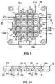
The module retention plate 40 is superposed on and tightly bonded to the air
flow path forming plate 26 to form a layered assembly, as shown in the bottom plan
view of Fig.9. Fig.10 shows a cross-sectional view taken along line X-X in Fig.9.
-
Referring to Figs.9 and 10, the module retention plate 40 is tightly bonded to
the air flow path forming plate 26 so that the center of the circular openings 41 formed
in the module retention plate 40 will be coincident with the points of intersection 36
of the lattice 30 forming the square-shaped openings 29 of the air flow path forming
plate 26 and so that the points of intersection 43 of a lattice 42 forming the circular
openings 41 of the module retention plate 40 will be coincident with the center of the
square-shaped openings 29 formed in the air flow path forming plate 26.
-
The result is that, as shown in Fig.9, of the circular openings 41 formed in the
module retention plate 40, the nine centrally located openings 41 communicate with
the square-shaped openings 29 formed in the air flow path forming plate 26.
-
Referring now to Fig. 10, the circular opening 41 located at the upper mid
portion communicates with the two neighboring square-shaped openings 29 and the
cut- outs 27a, 28a, formed in the air flow path forming plate 26, whilst the circular
opening 41 located at the right mid portion communicates with the two neighboring
square-shaped openings 29 and the cut- outs 27d, 28d, formed in the air flow path
forming plate 26, with the circular opening 41 located at the lower mid portion
communicating with the two neighboring square-shaped openings 29 and the cut- outs
27c, 28c, formed in the air flow path forming plate 26, and with the circular opening
41 located at the lower left portion communicating with the two neighboring square-shaped
openings 29 and the cut- outs 27b, 28b, formed in the air flow path forming
plate 26
-
Referring to Fig.9, the remaining circular openings 41, formed in the module
retention plate 40, communicate with the two neighboring square-shaped openings 29
and the cut- outs 27a, 28a, 27b, 28b, 27c, 28c, 27d or 28d formed in the air flow path
forming plate 26.
-
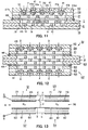
Fig.11 shows a schematic cross-sectional view showing the state of
communication between the openings 9, 12 and 13 formed in the hydrogen gas flow
path forming plate 6 and the openings 2, 3 formed in the hydrogen electrode plate 1
of the fuel cell according to the present invention, and the state of communication
between the openings 22, 23 formed in the oxygen electrode plate 21, the opening 29
formed in the air flow path forming plate 26 and the opening 41 formed in the module
retention plate 40.
-
Referring to Fig.11, the unit fuel cell forming the fuel cell according to the
present invention includes a hydrogen gas flow path forming plate 6, a hydrogen
electrode plate 1, a proton conductor film 45 capable of permeating protons yielded
on dissociation of hydrogen supplied to the hydrogen electrode plate 1, under the
action of a catalyst contained in the hydrogen electrode plate 1, an oxygen electrode
plate 21, an air flow path forming plate 26 and a module retention plate 40, layered in
this order.
-
Specifically, the hydrogen gas flow path forming plate 6 is tightly contacted
with and secured to the back side portion 18 of the back light of a liquid crystal
display, not shown, of a personal computer, and the hydrogen electrode plate 1 is
tightly bonded to the hydrogen gas flow path forming plate 6.
-
The proton conductor film 45 then is layered on and tightly bonded to the
hydrogen electrode plate 1, whilst the oxygen electrode plate 21 is layered on and
tightly bonded to the proton conductor film 45.
-
The air flow path forming plate 26 is also tightly contacted with and bonded to
the oxygen electrode plate 21, after which set screws, not shown, are threaded into
tapped holes, not shown, formed in the hydrogen gas flow path forming plate 6,
hydrogen electrode plate 1, oxygen electrode plate 21, air flow path forming plate 26
and in the module retention plate 40 for securing these components to the back side
portion 18 of the back light.
-
The peripheral portions of the proton conductor film 45 are sealed with sealing
members 46, as shown in Fig.11.
-
With the fuel cell of the present invention constructed as described above, the
hydrogen gas, supplied from the hydrogen gas supplying unit 17 into the inside of the
fuel cell, flows through a space between the hydrogen electrode plate 1 and the back
side portion 18 of the back light, as it is spread two-dimensionally, and as it repeatedly
contacts the hydrogen electrode plate 1, as described above, until it is ejected through
the hydrogen gas ejection unit 19 to outside the fuel cell.
-
The hydrogen supplied to the hydrogen electrode plate 1 is dissociated into
protons and electrons, by the action of the catalyst contained in the hydrogen electrode
plate 1, with the electrons being absorbed by the hydrogen electrode plate 1 and with
the protons being sent through proton conductor film 45 to the oxygen electrode plate
21. The electrons absorbed by the hydrogen electrode plate 1 are sent through a load,
not shown, to the oxygen electrode plate 21.
-
The air is sent into the inside of the fuel cell, through each of the circular
openings 41 formed in the module retention plate 40, as indicated by arrow Y in
Fig.11.
-
The air supplied to the nine openings 41, formed in a mid portion of the module
retention plate 40, flows into four neighboring square-shaped openings 29 formed in
the air flow path forming plate 26.
-
In Fig.10, the air supplied to the circular opening 41 formed at an upper mid
portion flows into two neighboring square-shaped openings 29 and the cut- outs 27a,
28a formed in the air flow path forming plate 26, whilst the air supplied to the circular
opening 41 formed at a mid left end portion flows into two neighboring square-shaped
openings 29 and into the cut- outs 27b, 28b formed in the air flow path forming plate
26.
-
Also, in Fig.10, the air supplied to the circular opening 41 formed at a lower
mid portion flows into two neighboring square-shaped openings 29 and the cut- outs
27c, 28c formed in the air flow path forming plate 26, whilst the air supplied to the
circular opening 41 formed at a mid right end portion flows into two neighboring
square-shaped openings 29 and the cut- outs 27d, 28d formed in the air flow path
forming plate 26.
-
The air supplied to the remaining circular openings 41 formed in the module
retention plate 40 flows into two neighboring square-shaped openings 22 and the cut- outs
27a, 28a, 27b, 28b, 27c, 28c, 27d, 28d formed in the air flow path forming plate.
-
That is, of the air flowing into the square-shaped openings 29 formed in the air
flow path forming plate 26, the air flowing into the four openings 29 in the mid portion
flows into four neighboring openings 22 formed in the oxygen electrode plate 21,
whilst the air flowing into the four square-shaped opening 29 at the four corners in
Fig.6 flows into one square-shaped opening 22 and into two triangular openings 23
formed in the oxygen electrode plate 21.
-
On the other hand, the air flowing into the remaining square-shaped openings
29 formed in the air flow path forming plate 26 flows into neighboring three square-shaped
openings 22 and into two triangular openings 23 formed in the oxygen
electrode plate 21.
-
The air flowing into the cut- outs 27a, 28a, 27b, 28b, 27c, 28c, 27d, 28d formed
in the air flow path forming plate 26 flows into one square-shaped opening 22 and one
triangular opening 23 formed in the oxygen electrode plate 21.
-
The air also flows from the cut- outs 27a, 28a, 27b, 28b, 27c, 28c, 27d, 28d
formed in two positions in each side of the air flow path forming plate 26 into the
square-shaped openings 22 and into the triangular openings 23 formed in the oxygen
electrode plate 21.
-
In this manner, air is supplied through the openings 41 formed in the module
retention plate 40 into the opening 29 and the cut- outs 27a, 28a, 27b, 28b, 27c, 28c,
27d, 28d, formed in the air flow path forming plate 26, while being supplied from the
cut- outs 27a, 28a, 27b, 28b, 27c, 28c, 27d, 28d formed in two positions in each side
of the air flow path forming plate 26 and into the square-shaped openings 22 and into
the triangular openings 23 formed in the oxygen electrode plate 21.
-
The result is that oxygen contained in the air is absorbed in the hydrogen
electrode plate 1 and is combined with electrons routed to the oxygen electrode plate
21 through a load, not shown, and with protons routed to the oxygen electrode plate
21 through the proton conductor film 45 to yield water.
-
So, the electromotive force is produced across the hydrogen electrode plate 1
and the oxygen electrode plate 21 to cause current to flow in the load.
-
In the present embodiment, the hydrogen gas flow path forming plate 6 is
superposed on the hydrogen electrode plate 1 so that the points of intersection 15 of
the lattice 4 forming the square-shaped openings 2 and the square-shaped openings 3
of the hydrogen electrode plate 1 will be in coincidence with the center of the square-shaped
openings 9 formed in the hydrogen gas flow path forming plate 6 and so that
the points of intersection 16 of the lattice 10 forming the small-sized square-shaped
openings 12 and the rectangular openings 13 of the hydrogen gas flow path forming
plate 6 will be in coincidence with the center of the square-shaped openings 2 formed
in the hydrogen electrode plate 1, as shown in Fig.3. The result is that the respective
square-shaped openings 9 formed in the hydrogen gas flow path forming plate 6
communicate with the square-shaped openings 2 and four of the triangular openings
3 formed in the hydrogen electrode plate 1, whilst the respective small-sized square-shaped
openings 12 formed in the hydrogen gas flow path forming plate 6
communicate with one of the square-shaped openings 2 formed in the hydrogen
electrode plate 1, with the rectangular openings 13 formed in the hydrogen gas flow
path forming plate 6 communicating with one another, as shown in Fig.3.
Additionally, the rectangular openings 13, except the two rectangular openings 13
communicating with the first cut-out 7, communicate with both the square-shaped
openings 2,3 formed in the hydrogen electrode plate 1. The two rectangular openings
13, formed in the hydrogen gas flow path forming plate 6 in communication with each
other and with the first cut-out 7, are in communication with one square-shaped
opening 2 and with two triangular openings 3 formed in the hydrogen electrode plate
1.
-
In the above-described arrangement, the hydrogen gas supplied from the
hydrogen gas supplying unit 17 to each of the square-shaped openings 9 formed in the
hydrogen gas flow path forming plate 6 flows into the square-shaped openings 2 and
four of the triangular openings 3 formed in the hydrogen electrode plate 1, whilst the
hydrogen gas supplied to the small-sized square-shaped openings 12 formed in the
hydrogen gas flow path forming plate 6 flows into one of the square-shaped openings
2 formed in the hydrogen electrode plate 1. The hydrogen gas supplied to the
rectangular openings 13 formed in the hydrogen gas flow path forming plate 6 flows
into the square-shaped openings 2 and the triangular openings 3, formed in the
hydrogen electrode plate 1, without flowing into the two rectangular openings 13
communicating with each other and with the first cut-out 7. Moreover, the hydrogen
gas, supplied to the two rectangular openings 13 communicating with the first cut-out
7, flows into the sole square-shaped opening 2 and two rectangular openings 3 formed
in the hydrogen electrode plate 1.
-
According to the present invention, in which the hydrogen electrode plate and
the hydrogen gas flow path forming plate 6 are superposed together, as described
above, each of the square-shaped openings 2 formed in the hydrogen electrode plate
1, excluding the square-shaped opening 2 located at the upper end in Fig.1,
communicates with the square-shaped openings 9, small-sized square-shaped openings
12 and four of the rectangular openings 13, formed in the hydrogen gas flow path
forming plate 6, such that only the square-shaped opening 2 located at the upper end
in Fig.1 communicates with each other and with the two neighboring square-shaped
openings 9 formed in the hydrogen gas flow path forming plate 6, while
communicating with two rectangular openings 13 communicating in turn with the first
cut-out 7. Additionally, each of the triangular openings 3 formed in the hydrogen
electrode plate 1 communicates with the square-shaped openings 9 and the rectangular
openings 13 formed in the hydrogen gas flow path forming plate 6, as shown in Fig.3.
-
The result is that the hydrogen gas, flowing into each of the square-shaped
openings 2 formed in the hydrogen electrode plate 1, except the square-shaped
opening 2 located at the upper end in Fig.1, flows into the square-shaped openings 9,
small-sized square-shaped opening 12 and four of the rectangular openings 13, formed
in the hydrogen gas flow path forming plate 6, while the hydrogen gas, flowing into
the square-shaped opening 2 located at the upper end in Fig.1, flows into two square-shaped
openings 9, formed in the hydrogen gas flow path forming plate 6 in
communication with each other and into two rectangular openings 13 communicating
with each other and with the first cut-out 7. Additionally, the hydrogen gas, flowing
into each of the triangular openings 3 formed in the hydrogen electrode plate 1, flows
into the square-shaped openings 9 and into the rectangular openings 13.
-
Since the hydrogen gas, supplied from the hydrogen gas supplying unit 17 into
the inside of the fuel cell, flows through a space between the hydrogen electrode plate
1 and the back side portion 18 of the back light, as it is spread two-dimensionally, and
as it repeatedly contacts the hydrogen electrode plate 1, as described above, so as to
be ejected through the hydrogen gas ejection unit 19 to outside the fuel cell, the
hydrogen gas may be allowed to contact the hydrogen electrode plate 1 efficiently,
thus improving the power generation efficiency of the fuel cell.
-
Moreover, it is sufficient if the hydrogen electrode plate 1, including 13 square-shaped
opening 2 and eight square-shaped opening 3 regularly arrayed by the lattice
4, and the hydrogen gas flow path forming plate 6, including the first cut-out 7,
forming the hydrogen gas supplying unit, the second cut-out 8, forming the hydrogen
gas ejection unit, 12 square-shaped openings 9 of the same size as the square-shaped
opening 2 formed in the hydrogen electrode plate 1, four small-sized square-shaped
opening 12 and eight rectangular openings 13, are superposed together so that the
points of intersection 15 of the lattice 4 forming the square-shaped opening 2 and the
square-shaped opening 3 of the hydrogen electrode plate 1 will be coincident with the
center of the square-shaped openings 9 formed in the hydrogen gas flow path forming
plate 6, and so that the points of intersection 16 of the lattice 10 forming the square-shaped
openings 9, small-sized square-shaped openings 12 and the rectangular
openings 13 of the hydrogen gas flow path forming plate 6 will be coincident with the
center of the square-shaped openings 2 formed in the hydrogen electrode plate 1, as
shown in Fig.3. Then, such a fuel cell may be produced in which the machining
operation is that easy, the structure is simplified and the hydrogen gas may be supplied
into efficient contact with the hydrogen electrode plate 1 to improve the power
generation efficiency.
-
The module retention plate 40 is tightly bonded to the air flow path forming
plate 26 so that the center of each of the circular openings 41 formed in the module
retention plate 40 will be coincident with the points of intersection 36 of the lattice 30
forming the square-shaped openings 29 of the air flow path forming plate 26, as shown
in Fig.10. The result is that nine circular openings 41 located at a mid portion of the
circular openings 41 formed in the module retention plate 40 communicate with the
four neighboring square-shaped openings 29 formed in the air flow path forming plate
26, the circular openings 41 located at the upper mid portion in Figs.8 and 10
communicate with the two neighboring square-shaped openings 29 and cut- outs 27a,
28a formed in the air flow path forming plate 26, as shown in Fig.10, the circular
openings 41 located at the right mid portion communicate with the two neighboring
square-shaped openings 29 and cut- outs 27b, 28b formed in the air flow path forming
plate 26, the circular openings 41 located at the lower mid portion communicates with
the two neighboring square-shaped openings 29 and cut- outs 27c, 28c formed in the
air flow path forming plate 26 and the circular openings 41 located at the left mid
portion communicate with the two neighboring square-shaped openings 29 and cut- outs
27d, 28d formed in the air flow path forming plate 26. The remaining circular
openings 41formed in the module retention plate 40 communicate with two
neighboring square-shaped openings 29 and cut- outs 27a, 28a, 27b, 28b, 27c, 28c, 27d,
28d formed in the air flow path forming plate 26, as shown in Fig.10.
-
In this manner, the air supplied to the nine mid openings 41 formed in the
module retention plate 40 flows into the four neighboring square-shaped openings 29
formed in the air flow path forming plate 26, while the air supplied to the circular
openings 41 located at the upper mid portion in Figs.8 and 10 flows into two
neighboring square-shaped openings 29 and cut- outs 27a, 28a formed in the air flow
path forming plate 26. The air supplied to the circular openings 41 located at the right
mid portion flows into two neighboring square-shaped openings 29 and cut- outs 27b,
28b formed in the air flow path forming plate 26. On the other hand, the air supplied
to the circular openings 41 located at the lower mid portion in Figs.8 and 10 flows into
two neighboring square-shaped openings 29 and cut- outs 27c, 28c formed in the air
flow path forming plate 26 and the air supplied to the circular openings 41 located at
the left mid portion flows into two neighboring square-shaped openings 29 and cut- outs
27d, 28d formed in the air flow path forming plate 26. The air supplied to the
remaining circular openings 41 formed in the module retention plate 40 flows into the
two neighboring square-shaped openings 29 and cut- outs 27a, 28a, 27b, 28b, 27c, 28c,
27d, 28d formed in the air flow path forming plate 26.
-
With the above-described fuel cell according to the present invention, the
oxygen electrode plate 21 and the air flow path forming plate 26 are superposed
together so that the points of intersection 35 of the lattice 24 forming the square-shaped
openings 22 and the triangular openings 23 of the oxygen electrode plate 21
will be coincident with the center of the square-shaped openings 29 formed in the air
flow path forming plate 26 and so that the points of intersection 36 of the lattice 30
forming the square-shaped openings 29 formed in the air flow path forming plate 26
will be coincident with the center of the square-shaped opening 22 formed in the
oxygen electrode plate 21. As a result, the square-shaped openings 22 formed in the
oxygen electrode plate 21, except the openings 29 located at upper, lower, left and
right ends in Fig.5, communicate with the four neighboring square-shaped openings
29 formed in the air flow path forming plate 26, the opening 29 located at an upper end
communicates with the two neighboring square-shaped opening 29 and the cut- outs
27a, 28a, formed in the air flow path forming plate 26, the opening 29 located at a
right end communicates with the two neighboring square-shaped opening 29 and the
cut- outs 27b, 28b, formed in the air flow path forming plate 26, and the opening 29
located at a lower end communicates with the two neighboring square-shaped opening
29 and the cut- outs 27c, 28d, formed in the air flow path forming plate 26. The
opening 29 located at the left end communicates with the two neighboring square-shaped
opening 29 and the cut- outs 27d, 28d, formed in the air flow path forming plate
26. The triangular openings 23 formed in the oxygen electrode plate 21 communicate
with the two neighboring square-shaped opening 29 and with the cut- outs 27a, 28a,
27b, 28b, 27c, 28c, 27d, 28d. The mid four square-shaped openings 29 of the square-shaped
openings 29 formed in the air flow path forming plate 26 communicate with
the four neighboring square-shaped openings 22 formed in the oxygen electrode plate
21. The four square-shaped openings 29 lying at the four corners communicate with
the sole square-shaped opening 22 and the triangular opening 23 formed in the oxygen
electrode plate 21, while the remaining square-shaped openings 29 formed in the air
flow path forming plate 26 communicate with the three neighboring square-shaped
openings 22 and two of the triangular openings 23 formed in the oxygen electrode
plate 21. On the other hand, the cut- outs 27a, 28a, 27b, 28b, 27c, 28c, 27d, 28d
formed in the air flow path forming plate 26 communicate with the sole square-shaped
opening 22 and the sole triangular opening 23 formed in the oxygen electrode plate 21.
-
The result is that the air supplied to nine openings 41 located at a mid portion
of the module retention plate 40 flows into the four neighboring square-shaped
openings 29 formed in the air flow path forming plate 26, while the air supplied to the
circular openings 41 at the upper mid portion in Figs.8 and 10 flows into two
neighboring square-shaped openings 29 and the cut- outs 27a, 28a, formed in the air
flow path forming plate 26, whilst the air supplied to the circular openings 41 at the
right mid portion flows into two neighboring square-shaped openings 29 and the cut- outs
27b, 28b formed in the air flow path forming plate 26. The air supplied to the
circular openings 41 at the lower mid portion in Figs.8 and 10 flows into two
neighboring square-shaped openings 29 and the cut- outs 27c, 28c, formed in the air
flowpath forming plate 26, while the air supplied to the circular openings 41 at the left
mid portion in Figs.8 and 10 flows into two neighboring square-shaped openings 29
and the cut- outs 27d, 28d, formed in the air flow path forming plate 26. The air
supplied into the remaining circular openings 41 formed in the air flow path forming
plate 26 flows into the two neighboring square-shaped openings 29 and the cut- outs
27a, 28a, 27b, 28b, 27c, 28c, 27d, 28d, formed in the air flow path forming plate 26.
The air flowing into the four mid openings 29 of the air flowing into the square-shaped
openings 29 in the air flow path forming plate 26 flows into four neighboring square-shaped
openings 22 formed in the oxygen electrode plate 21, while the air flowing into
the four square-shaped openings 22 formed at the four corners in Fig.6 flows into the
sole square-shaped opening 22 and into the two triangular openings 23 formed in the
oxygen electrode plate 21. On the other hand, the air flowing into the remaining
square-shaped openings 29 formed in the air flow path forming plate 26 flows into the
three neighboring square-shaped opening 22 and two triangular openings 23 formed
in the oxygen electrode plate 21. Additionally, the air flowing into the cut- outs 27a,
28a, 27b, 28b, 27c, 28c, 27d, 28d formed in the air flow path forming plate 26 flows
into the sole square-shaped opening 22 and into the sole triangular opening 23 formed
in the oxygen electrode plate 21.
-
In this manner, the air is supplied through the opening 21 formed in the module
retention plate 40 into the opening 29 and the cut- outs 27a, 28a, 27b, 28b, 27c, 28c,
27d, 28d formed in the air flow path forming plate 26 and further into the square-shaped
opening 22 and two triangular openings 23 formed in the oxygen electrode
plate 21, so that oxygen may be brought efficiently into contact with the oxygen
electrode plate 21 to improve the power generation efficiency of the fuel cell
significantly.
-
Moreover, since it is sufficient if the oxygen electrode plate 21, having 12
square-shaped openings 22 and eight square-shaped openings 23 arrayed in a regular
pattern by the lattice 24, air flow path forming plate 26, carrying 16 square-shaped
openings 29 of the same size as the opening 22 formed in the oxygen electrode plate
21 and the cut- outs 27a, 28a, 27b, 28b, 27c, 28c, 27d, 28d, and the module retention
plate 40 having a regular array of 21 circular openings 41, are layered in this order,
such a fuel cell may be produced in which the machining operation is that easy, the
structure is simplified and the hydrogen gas may be supplied into efficient contact with
the hydrogen electrode plate 1 to improve the power generation efficiency.
-
In the above-described embodiment, the hydrogen electrode plate 1 and the
hydrogen gas flow path forming plate 6 are superposed and bonded tightly together so
that the points of intersection 15 of the lattice 4 forming the square-shaped openings
2 and the triangular openings 3 of the hydrogen electrode plate 11 will be coincident
with the center of the square-shaped openings 9 formed in the air flow path forming
plate 6 and so that the points of intersection 16 of the lattice 10 forming the square-shaped
openings 9, the small-sized square-shaped openings 12 and the rectangular
openings 13 formed in the hydrogen gas flow path forming plate 6 will be coincident
with the center of the square-shaped openings 2 formed in the hydrogen electrode plate
1.
-
Moreover, the air flow path forming plate 26 is superposed and bonded tightly
to the oxygen electrode plate 21 so that the points of intersection 35 of the lattice 24
forming the square-shaped openings 22 and the triangular openings 23 of the oxygen
electrode plate 21 will be coincident with the center of the square-shaped openings 29
formed in the air flow path forming plate 26 and so that the points of intersection 36
of the lattice 30 forming the square-shaped openings 29 formed in the air flow path
forming plate 26 will be coincident with the center of the square-shaped openings 22
formed in the oxygen electrode plate 21. Additionally, the module retention plate 40
is tightly bonded to the air flow path forming plate 26 so that the center of the circular
openings 41 formed in the module retention plate 40 will be coincident with the points
of intersection 36 of the lattice 30 forming the square-shaped openings 29 of the air
flow path forming plate 26, and so that the points of intersection 43 of the lattice 42
forming the circular openings 41 of the module retention plate 40 will be coincident
with the center of the square-shaped openings 29 formed in the air flow path forming
plate 26, as shown in Fig.10.
-
With the above-described structure, the force applied to the module retention
plate 40 is transmitted in a distributed fashion to the air flow path forming plate 26 and
thence to the oxygen electrode plate 21, again in a distributed fashion. The force
transmitted to the oxygen electrode plate 21 is transmitted through a seal 46 to the
hydrogen electrode plate 1, but is transmitted to the hydrogen gas flow path forming
plate 6, again in a distributed fashion. So, the force applied to the module retention
plate 40 is positively distributed and applied homogeneously to the entire fuel cell 1,
so that the proton conductor film 45 may contact the hydrogen electrode plate 1 and
the oxygen electrode plate 21 homogeneously to improve the power generation
efficiency.
-
Fig.12 shows a modification of the fuel cell according to the present invention.
Fig. 12 is a cross-sectional view showing a modification of the invention and shows the
state of communication between the openings formed in the respective members
making up the fuel cell.
-
Referring to Fig.12, the fuel cell of the present embodiment is comprised of a
first unit fuel cell 51 and a second unit fuel cell 52, layered together. The first unit
fuel cell 51 includes, as in the above-described fuel cell, a hydrogen gas flow path
forming plate 6, a hydrogen electrode plate 1, a proton conductor film 45, an oxygen
electrode plate 21, an air flow path forming plate 26 and a module retention plate 40,
layered in this order from below, whilst the second unit fuel cell 52 includes a
hydrogen gas flow path forming plate 6, a hydrogen electrode plate 60, a proton
conductor film 61, an oxygen electrode plate 62, an air flow path forming plate 63 and
a module retention plate 64, layered in this order from above. The first and second unit
fuel cells 51, 52 own a common hydrogen gas flow path forming plate 6. In Fig.12,
65 denotes a sealing member.
-
In the present fuel cell, the hydrogen electrode plate 60, proton conductor film
61, oxygen electrode plate 62, air flow path forming plate 63 and the module retention
plate 64 are formed in the same way as the hydrogen electrode plate 1, proton
conductor film 45, oxygen electrode plate 21, air flow path forming plate 26 and the
module retention plate 40. The hydrogen electrode plate 60, proton conductor film 61,
oxygen electrode plate 62, air flow path forming plate 63 and the module retention
plate 64 are layered together so that the relative disposition of the hydrogen electrode
plate 51 and the hydrogen gas flow path forming plate 6, the relative disposition of the
oxygen electrode plate 53 and the air flow path forming plate 54 and the relative
disposition of the air flow path forming plate 54 and the module retention plate 55 will
be the same as the relative disposition of the hydrogen electrode plate 1 and the
hydrogen gas flow path forming plate 6, the relative disposition of the oxygen
electrode plate 21 and the air flow path forming plate 26 and the relative disposition
of the air flow path forming plate 26 and the module retention plate 40, respectively.
-
In the present embodiment of the fuel cell, the first and second unit fuel cells
51, 52 can be coupled to each other in an optional fashion to form a fuel cell by
selectively severing or leaving intact the pins A to H for electrode interconnection
formed in the oxygen electrode plates 21, 62 and in the hydrogen electrode plates 1,
60.
-
If the pins A to H for electrode interconnection formed in the
oxygen electrode
plates 21, 62 and in the
hydrogen electrode plates 1, 60 are to be selectively severed
or left intact, as shown in the following Table 1:
| electrodes | A | B | C | D | E | F | G | H | |
| 26 | | | | | 0 |
| 1 | 0 | | 0 | 0 |
| 60 | | | 0 | 0 | 0 |
| 62 | | 0 |
th first and second unit fuel cells are connected in series with each other.
-
In Table 1, [0] denotes that the relevant pin for electrode interconnection is left
intact without cutting.
-
That is, in the oxygen electrode plate 21 forming the first unit fuel cell 51, the
pin for electrode interconnection E only is left, with the pins for electrode
interconnection A, B, C, D, F, G and H being severed, whereas, in the oxygen
electrode plate 60 forming the second unit fuel cell 52, the pins C, D and E for
electrode interconnection are left, with the pins for electrode interconnection A, B, F,
G and H being severed. The pin for electrode interconnection E formed in the oxygen
electrode plate 21 forming the first unit fuel cell 51 is bent downwards, whereas the
pin for electrode interconnection E formed in the hydrogen electrode plate 60 forming
the second unit fuel cell 52 is bent upwards and coupled to the pin for electrode
interconnection E formed in the oxygen electrode plate.
-
As a result, the first and second unit fuel cells 51, 52 are connected in series
with each other.
-
On the other hand, in the hydrogen electrode plate 1 forming the first unit fuel
cell 51, the pins for electrode interconnection A, C and D are left, with the pins for
electrode interconnection B, E, F, G and H being severed, whereas, in the oxygen
electrode plate 62 forming the second unit fuel cell 52, only the pin for electrode
interconnection B is left, with the pins for electrode interconnection A, C, D, E, F, G
and H being severed. The pin for electrode interconnection A, formed in the
hydrogen electrode plate 1 forming the first unit fuel cell 51, and the pin for electrode
interconnection B, formed in the oxygen electrode plate 62, forming the second unit
fuel cell 52, are separately coupled to outputs.
-
If the pins for electrode interconnection A to H formed in the
oxygen electrode
plate 21 or 62 and in the
hydrogen electrode plate 1 or 60 are selectively severed or
left intact, as shown in Table 2:
| electrodes | A | B | C | D | E | F | G | H | |
| 26 | | | | | | 0 |
| 1 | 0 | | 0 | 0 | 0 |
| 60 | | | 0 | 0 | 0 |
| 62 | | 0 | | | | 0 |
the first and second
unit fuel cells 51, 52 are connected in parallel with each other.
-
That is, in the oxygen electrode plate 21 forming the first unit fuel cell 51, the
pin for electrode interconnection F measly is left, with the pins for electrode
interconnection A, B, C, D, E, G and H being severed, whereas, in the oxygen
electrode plate 60 forming the second unit fuel cell 52, the pins B and F for electrode
interconnection are left, with the pins for electrode interconnection A, C, D, F, G and
H being severed. The pin for electrode interconnection F formed in the oxygen
electrode plate 21 forming the first unit fuel cell 51 is bent downwards, whereas the
pin for electrode interconnection F formed in the oxygen electrode plate 62 forming
the second unit fuel cell 52 is bent upwards and coupled to the pin for electrode
interconnection F formed in the oxygen electrode plate.
-
Also, in the hydrogen electrode plate 1 forming the first unit fuel cell 51, the
pins for electrode interconnection A, C, D and E are left, with the pins for electrode
interconnection B, F, G and H being severed, whereas, in the hydrogen electrode plate
60 forming the second unit fuel cell 52, the pins C, D and E for electrode
interconnection are left, with the pins for electrode interconnection A, B, F, G and H
being severed. The pin for electrode interconnection F formed in the hydrogen
electrode plate 1 forming the first unit fuel cell 51 is bent downwards, whereas the pin
for electrode interconnection E formed in the hydrogen electrode plate 60 forming the
second unit fuel cell 52 is bent upwards and coupled to the pin for electrode
interconnection F formed in the oxygen electrode plate.
-
The result is that the first and second unit fuel cells 51, 52 are connected in
parallel with each other.
-
The pin for electrode interconnection A formed in the hydrogen electrode plate
1 forming the first unit fuel cell 51 and the pin for electrode interconnection B formed
in the oxygen electrode plate 62 forming the second unit fuel cell 52 are separately
coupled to outputs.
-
With the fuel cell, described above, the hydrogen gas path is fixed by the
hydrogen electrode plate 1, hydrogen gas flow path forming plate 6 and by the
hydrogen electrode plate 60, so that the hydrogen gas is supplied from the hydrogen
gas supplying unit 17 into a hydrogen gas path defined by the hydrogen electrode plate
1, hydrogen gas flow path forming plate 6 and by the hydrogen electrode plate 60.
Thus, the hydrogen gas flows through the hydrogen gas path, as it is spread two-dimensionally
as indicated by arrow Z in Fig.12, and as it repeatedly contacts the
hydrogen electrode plate 1, as described above, until it is ejected through the hydrogen
gas ejection unit 19 to outside the fuel cell.
-
On the other hand, the air supplied through the module retention plate 64 is
supplied to the oxygen electrode plate 62, as it is spread two-dimensionally, through
the air flow path forming plate 63, as is the air supplied through the module retention
plate 40.
-
With the above-described structure, the fuel cell may be constructed by
interconnecting the first unit fuel cell 51 and the second unit fuel cell 52 in an optional
mode of interconnection by selectively severing or leaving the pins for electrode
interconnection A to H formed in the oxygen electrode plate 21 or 62 and in the
hydrogen electrode plate 1 or 60.
-
Moreover, in the fuel cell of the present invention, the hydrogen electrode plate
1 and the hydrogen gas flow path forming plate 6 are superposed and tightly bonded
together so that the points of intersection 15 of the lattice 4 forming the square-shaped
openings 2 and the triangular openings 3 of the hydrogen electrode plate 11 will be
coincident with the center of the square-shaped openings 9 formed in the air flow path
forming plate 6 and so that the points of intersections 16 of the lattice 10 forming the
square-shaped openings 9, the small-sized square-shaped openings 12 and the
rectangular openings 13 formed in the hydrogen gas flow path forming plate 6 will be
coincident with the center of the square-shaped openings 2 formed in the hydrogen
electrode plate 1, as shown in Fig.3.
-
In the fuel cell according to the present invention, the air flow path forming
plate 26 is superposed on and tightly bonded to the oxygen electrode plate 21 so that,
as shown in Fig.7, the points of intersection 35 of the lattice 24 forming the square-shaped
openings 22 and the triangular openings 23 of the oxygen electrode plate 21
will be coincident with the center of the square-shaped openings 29 formed in the air
flow path forming plate 26 and so that the points of intersection 36 of the lattice 30
forming the square-shaped openings 29 formed in the air flow path forming plate 26
will be coincident with the center of the square-shaped openings 22 formed in the
oxygen electrode plate 21. Additionally, the module retention plate 40 is tightly
bonded to the air flow path forming plate 26 so that the center of each of the circular
openings 41 formed in the module retention plate 40 will be coincident with the points
of intersection 36 of the lattice 30 forming the square-shaped openings 29 of the air
flow path forming plate 26, and so that the points of intersection 43 of the lattice 42
forming the circular openings 41 of the module retention plate 40 will be coincident
with the center of the square-shaped openings 29 formed in the air flow path forming
plate 26, as shown in Fig. 10.
-
Moreover, the hydrogen electrode plate 60 forming the second unit fuel cell 52
and the hydrogen gas flow path forming plate 6 are superposed and tightly bonded to
each other with the equivalent relative positions to those of the hydrogen electrode
plate 1 and the hydrogen gas flow path forming plate 6 forming the first unit fuel cell
51, while the oxygen electrode plate 62 and the air flow path forming plate 63 forming
the second unit fuel cell 52 are superposed and tightly bonded to each other with the
equivalent relative positions to those of the oxygen electrode plate 21 and the air flow
path forming plate 26 forming the first unit fuel cell 51.
-
With the above-described structure, the force applied to the module retention
plate 40 of the first unit fuel cell 51 is transmitted in a distributed fashion to the air
flow path forming plate 26 and thence to the oxygen electrode plate 21, again in a
distributed fashion. The force transmitted to the oxygen electrode plate 21 is
transmitted through a seal 46 to the hydrogen electrode plate 1, but is transmitted to
the hydrogen gas flow path forming plate 6, again in a distributed fashion. On the
other hand, the force applied to the module retention plate 64 of the second unit fuel
cell 52 is transmitted in a distributed fashion to the air flow path forming plate 63 and
thence to the oxygen electrode plate 62, again in a distributed fashion. The force
transmitted to the oxygen electrode plate 62 is transmitted through a seal 65 to the
hydrogen electrode plate 60, but is transmitted to the hydrogen gas flow path forming
plate 6, again in a distributed fashion. So, the force applied to the module retention
plates 40,64 is positively distributed and applied homogeneously to the entire fuel cell
1, so that the proton conductor film 45 may contact the hydrogen electrode plate 1 and
the oxygen electrode plate 21 homogeneously to improve the power generation
efficiency.
-
A further embodiment of the present invention is explained by referring to the
drawings.
-
Referring to Fig. 13, the fuel cell of the present embodiment is comprised of a
first unit fuel cell 51, a second unit fuel cell 52, a third unit fuel cell 53 and a fourth
unit fuel cell 54. The first unit fuel cell 51 includes the hydrogen gas flow path
forming plate 6, hydrogen electrode plate 1, proton conductor film 45, oxygen
electrode plate 21, air flow path forming plate, not shown, and a module retention
plate, not shown, layered in this order from below, whilst the second unit fuel cell 52
includes a hydrogen gas flow path forming plate 6, a hydrogen electrode plate 60, a
proton conductor film 61, an oxygen electrode plate 62, an air flow path forming plate,
not shown, and a module retention plate, also not shown, layered in this order from
above. The third unit fuel cell 53 includes a hydrogen gas flow path forming plate 76,
a hydrogen electrode plate 70, a proton conductor film 71, an oxygen electrode plate
72, an air flow path forming plate, not shown, and a module retention plate, also not
shown, layered in this order from below, as in the first unit fuel cell 51, whilst the
fourth unit fuel cell 54 includes a hydrogen gas flow path forming plate 76, a hydrogen
electrode plate 80, a proton conductor film 81, an oxygen electrode plate 82, an air
flow path forming plate, not shown, and a module retention plate, also not shown,
layered in this order from above, as in the second unit fuel cell 52.
-
The oxygen electrode plate 72 of the third unit fuel cell 53 is mounted with
respect to the oxygen electrode plate 21 of the first unit fuel cell 51, with the front and
back sides reversed, line-symmetrically with respect to a straight line passing through
neighboring portion, so that pins for electrode interconnection E, F, G and H thereof
will face pins for electrode interconnection E, F, G and H of the oxygen electrode
plate 21 of the first unit fuel cell 51, as shown in Fig.14.
-
Although not shown, the relationship between the hydrogen electrode plate 70
forming the third unit fuel cell 53 and the hydrogen electrode plate 1 forming the first
unit fuel cell 51 is similar to that described above, as is the relationship between the
hydrogen electrode plate 80 and the oxygen electrode plate 82 forming the fourth unit
fuel cell 54 and the hydrogen electrode plate 60 and the oxygen electrode plate 62
forming the second unit fuel cell 52.
-
In the fuel cell shown in Fig.13, the four unit fuel cells 51 to 54 can be
internally connected to one another in an optional connection mode by selectively
severing or leaving the pins A to H provided to the oxygen electrode plates 21, 62, 72,
82 and to the hydrogen electrode plates 1, 60, 70 and 80 forming the four unit fuel
cells 51 to 54.
-
If the pins A to H provided to the oxygen electrode plates and to the hydrogen
electrode plates, forming the respective
unit fuel cells 51 to 54, are selectively
severed, as shown in Table 3:
| electrodes | A | B | C | D | E | F | G | H | |
| 21 | | | | | 0 | 0 |
| 1 | 0 | | 0 | 0 | | 0 |
| 60 | | | 0 | 0 | | 0 | 0 |
| 62 | | 0 | | | | | | 0 |
| 72 | | | | | 0 |
| 70 | | | 0 | 0 | | 0 |
| 80 | | | 0 | 0 | | | 0 |
| 82 | | | | | | | | 0 |
two of the four
unit fuel cells 51 to 54 making up the fuel cell are connected in series
with each other, while the remaining two are connected in parallel with each other.
-
That is, in the oxygen electrode plate 21 forming the first unit fuel cell 51, only
the pins for electrode interconnection E, F are left intact, with the remaining pins A,
B, C, D, G and H being severed, whereas, in the oxygen electrode plate 72 forming the
third unit fuel cell 53, only the pin for electrode interconnection E is left intact, with
the remaining pins A, B, C, D, F, G and H being severed. In the hydrogen electrode
plate 1 forming the first unit fuel cell 51, the pins for electrode interconnection A, C,
D and F are left intact, with the remaining pins B, E, G and H being severed, whereas,
in the hydrogen electrode plate 70, forming the third unit fuel cell 53, the pins for
electrode interconnection C, D and F are left intact, with the remaining pins A, B, E,
G and H being severed. It is noted that, in the oxygen electrode plate 21 and the
hydrogen electrode plate 1, forming the first unit fuel cell 51, and in the oxygen
electrode plate 72 and the hydrogen electrode plate 70, forming the third unit fuel cell
53, the pins among the facing pins for electrode interconnection A to H that are left
without severing abut against one another for electrical connection. So, the oxygen
electrode plate 21 forming the first unit fuel cell 51 and the oxygen electrode plate 72
forming the third unit fuel cell 53 are electrically interconnected by the pin for
electrode interconnection E, whilst the hydrogen electrode plate 1 forming the first
unit fuel cell 51 and the hydrogen electrode plate 70 forming the third unit fuel cell 53
are electrically interconnected by the pin for electrode interconnection F.
-
Moreover, in the hydrogen electrode plate 60 forming the second unit fuel cell
52, only the pins for electrode interconnection C, D, F and G are left intact, with the
remaining pins A, B, C, E and H being severed, whereas, in the hydrogen electrode
plate 80 forming the fourth unit fuel cell 54, the pins for electrode interconnection C,
D and G are left intact, with the remaining pins A, B, E, F and H being severed. In the
oxygen electrode plate 62 forming the second unit fuel cell 52, only the pins for
electrode interconnection B and H are left intact, with the remaining pins A, C, D, E,
F and G being severed, whereas, in the oxygen electrode plate 82, forming the fourth
unit fuel cell 54, only the pin for electrode interconnection H is left intact, with the
remaining pins A to G being severed. It is noted that, in the hydrogen electrode plate
60 and the oxygen electrode plate 62, forming the second unit fuel cell 52, and in the
hydrogen electrode plate 80 and the oxygen electrode plate 82, forming the fourth unit
fuel cell 54, the pins among the facing pins for electrode interconnection A to H that
are left without severing abut against one another for electrical connection. So, the
hydrogen electrode plate 60 forming the second unit fuel cell 52 and the hydrogen
electrode plate 80 forming the fourth unit fuel cell 54 are electrically interconnected
by the pin for electrode interconnection H, whilst the oxygen electrode plate 62
forming the second unit fuel cell 52 and the oxygen electrode plate 82 forming the
fourth unit fuel cell 54 are electrically interconnected by the pin for electrode
interconnection H.
-
As a result, the first unit fuel cell 51 and the third unit fuel cell 53 are connected
in parallel with each other, whilst the second unit fuel cell 52 and the fourth unit fuel
cell 54 are connected in parallel with each other.
-
The pin for electrode interconnection F formed on the oxygen electrode plate
21 forming the first unit fuel cell 51 is bent downwards, whilst the pin for electrode
interconnection F formed on the hydrogen electrode plate 60 forming the second unit
fuel cell 52 is bent upwards and connected to the pin F formed on the oxygen electrode
plate 21, as a result of which a parallel connection of the first unit fuel cell 51 and the
third unit fuel cell 53 is connected in series with a parallel connection of the second
unit fuel cell 52 and the fourth unit fuel cell 54.
-
The pin for electrode interconnection A formed on the hydrogen electrode plate
1 forming the first unit fuel cell 51 and the pin for electrode interconnection B formed
on the oxygen electrode plate 62 forming the second unit fuel cell 52 are separately
connected to outputs.
-
Table 4 shows a method for selective severing of the pins for electrode
interconnection A to H formed in the oxygen electrode plate and in the hydrogen
electrode plate in case the four
unit fuel cells 51 to 54 are all connected in series to
constitute a fuel cell:
| electrodes | A | B | C | D | E | F | G | H | |
| 21 | | | | | 0 |
| 1 | 0 | | 0 | 0 |
| 60 | | | 0 | 0 | | | 0 |
| 62 | | 0 |
| 72 | | | | | | 0 |
| 70 | | | 0 | 0 | 0 |
| 80 | | | 0 | 0 | | 0 |
| 82 | | | | | | | 0 |
-
That is, in the oxygen electrode plate 21 forming the first unit fuel cell 51, only
the pin for electrode interconnection E is left intact, with the remaining pins A, B, C,
D, F, G and H being severed, whereas, in the hydrogen electrode plate 70 forming the
third unit fuel cell 53, the pins for electrode interconnection C, D and E are left intact,
with the remaining pins A, B, F, G and H being severed. The pin for electrode
interconnection E formed on the oxygen electrode plate 21 forming the first unit fuel
cell 51 is bent downwards, whilst the pin for electrode interconnection E formed on
the hydrogen electrode plate 70 forming the is bent upwards and connected to the pin
E formed on the oxygen electrode plate 21, as a result of which first unit fuel cell 51
and the third unit fuel cell 53 are connected in series with each other.
-
On the other hand, in the hydrogen electrode plate 60 forming the second unit
fuel cell 52, only the pins for electrode interconnection C, D and G are left intact, with
the remaining pins A, B, C, D, F, G and H being severed, whereas, in the oxygen
electrode plate 82 forming the fourth unit fuel cell 54, only the pin for electrode
interconnection G is left intact, with the remaining pins A, B, C, D, E, F and H being
severed. The pin for electrode interconnection G formed on the oxygen electrode plate
82 forming the fourth unit fuel cell 54 is bent downwards, whilst the pin for electrode
interconnection G formed on the hydrogen electrode plate 70 forming the is bent
upwards and connected to the pin E formed on the oxygen electrode plate 82, as a
result of which second unit fuel cell 52 and the fourth unit fuel cell 54 are connected
in series with each other.
-
Also, in the oxygen electrode plate 72 forming the third unit fuel cell 53, only
the pin for electrode interconnection F is left intact, with the remaining pins A, B, C,
D, E, G and H being severed, whereas, in the hydrogen electrode plate 80 forming the
fourth unit fuel cell 54, only the pins for electrode interconnection C, D and F are left
intact, with the remaining pins A, B, E, G and H being severed. The pin for electrode
interconnection F formed on the oxygen electrode plate 72 forming the third unit fuel
cell 53 is bent downwards, whilst the pin for electrode interconnection F formed on the
hydrogen electrode plate 80 forming the fourth unit fuel cell 54 is bent upwards and
connected to the pin F formed on the oxygen electrode plate 72. Thus, the third unit
fuel cell 53 and the fourth unit fuel cell 54 are connected in series with each other, as
a result of which four unit fuel cells 51 to 54 are connected in series with each other.
-
Table 5 shows a method for selective severing of the pins for electrode
interconnection A to H formed in the oxygen electrode plate and in the hydrogen
electrode plate in case the four
unit fuel cells 51 to 54 are all connected in parallel to
constitute a fuel cell:
| electrodes | A | B | C | D | E | F | G | H | |
| 21 | | | | | 0 | | 0 |
| 1 | 0 | | 0 | 0 |
| 60 | | | 0 | 0 | | 0 |
| 62 | | 0 | | | | | 0 |
| 72 | | | | | 0 | | 0 |
| 70 | | | 0 | 0 | | 0 | | 0 |
| 80 | | | 0 | 0 | | 0 | | 0 |
| 82 | | | | | | | 0 |
-
That is, in the oxygen electrode plate 21 forming the first unit fuel cell 51, only
the pins for electrode interconnection E, G are left intact, with the remaining pins A,
B, C, D, F and H being severed, whereas, in the oxygen electrode plate 72 forming the
third unit fuel cell 53, only the pins for electrode interconnection E and G are left
intact, with the remaining pins A, B, C, D, F and H being severed. In the hydrogen
electrode plate 1 forming the first unit fuel cell 51, the pins for electrode
interconnection C, D, F and H are left intact, with the remaining pins A, B, E and G
being severed, whereas, in the hydrogen electrode plate 70, forming the third unit fuel
cell 53, the pins for electrode interconnection C, D, F and H are left intact, with the
remaining pins A, B, E and G being severed. It is noted that, in the oxygen electrode
plate 21 and the hydrogen electrode plate 1, forming the first unit fuel cell 51, and in
the oxygen electrode plate 72 and the hydrogen electrode plate 70, forming the third
unit fuel cell 53, the pins among the facing pins for electrode interconnection A to H
that are left without severing abut against one another for electrical connection. So,
the oxygen electrode plate 21 forming the first unit fuel cell 51 and the oxygen
electrode plate 72 forming the third unit fuel cell 53 are electrically interconnected by
the pin for electrode interconnection E, whilst the hydrogen electrode plate 1 forming
the first unit fuel cell 51 and the hydrogen electrode plate 70 forming the third unit fuel
cell 53 are electrically interconnected by the pin for electrode interconnection F.
-
Moreover, in the hydrogen electrode plate 60 forming the second unit fuel cell
52, only the pins for electrode interconnection C, D and F are left intact, with the
remaining pins A, B, E, G and H being severed, whereas the pin for electrode
interconnection F is bent upwards, with the pin for electrode interconnection F formed
on the hydrogen electrode plate 1 forming the first unit fuel cell 51 being bent
downwards for connection to the pin for electrode interconnection F of the hydrogen
electrode plate 60. In the oxygen electrode plate 62 forming the second unit fuel cell
52, only the pins for electrode interconnection B and G are left intact, with the
remaining pins A, C, D, E, F and H being severed, whereas the pin for electrode
interconnection G is bent upwards, with the pin for electrode interconnection G
formed on the oxygen electrode plate 21 forming the first unit fuel cell 51 being bent
downwards for connection to the pin for electrode interconnection G of the oxygen
electrode plate 62. So, the first unit fuel cell 51 and the second unit fuel cell 52 are
connected together in parallel via pins for electrode interconnection F and G.
-
Moreover, in the hydrogen electrode plate 80 forming the fourth unit fuel cell
54, only the pins for electrode interconnection C, D and F are left intact, with the
remaining pins A, B, E, G and H being severed, whereas the pin for electrode
interconnection F is bent upwards, with the pin for electrode interconnection F formed
on the hydrogen electrode plate 70 forming the third unit fuel cell 53 being bent
downwards for connection to the pin for electrode interconnection F of the hydrogen
electrode plate 80. In the oxygen electrode plate 82 forming the fourth unit fuel cell
54, only the pin for electrode interconnection G is left intact, with the remaining pins
A, B, C, D, E, F and H being severed, whereas the pin for electrode interconnection
G is bent upwards, with the pin for electrode interconnection G formed on the oxygen
electrode plate 72 forming the third unit fuel cell 53 being bent downwards for
connection to the pin for electrode interconnection G of the oxygen electrode plate 82.
So, the third unit fuel cell 53 and the fourth unit fuel cell 54 are connected together in
parallel via pins for electrode interconnection F and G.
-
So, the four unit fuel cells 51 to 54 are all connected to one another in parallel
to form a fuel cell.
-
The fuel cell having the above structure can be constituted by interconnecting
the four unit fuel cells 51 to 54 in optional connecting mode measly by selectively
severing the pins for electrode interconnection A to H formed on the oxygen electrode
plate and the hydrogen electrode plate forming the unit fuel cells 51 to 54 to leave the
non-selected pins intact, without the necessity of providing conductors for connection.
-
The present invention can be modified within the scope of the invention without
being limited to the above-described embodiments.
-
For example, the hydrogen electrode plate 1 and the hydrogen gas path forming
plate 6 are superposed on and tightly bonded to each other so that the points of
intersection 15 of the lattice 4 forming the square-shaped openings 2 and the triangular
openings 3 of the hydrogen electrode plate 11 will be coincident with the center of the
square-shaped openings 9 formed in the air flow path forming plate 6 and so that the
points of intersections 16 of the lattice 10 forming the square-shaped openings 9,
small-sized square-shaped openings 12 and the rectangular openings 13 will be
coincident with the center of the square-shaped openings 2 of the formed in the
hydrogen electrode plate 1. However, it is not mandatory to have the hydrogen
electrode plate 1 and the hydrogen gas path forming plate 6 tightly bonded together in
this manner since it is only sufficient if the hydrogen electrode plate 1 and the
hydrogen gas path forming plate 6 are tightly bonded together so that each of the plural
openings formed in the hydrogen electrode plate 1 communicates with two or more of
the plural openings formed in the hydrogen gas flow path forming plate 6, with each
of the plural openings formed in the hydrogen gas flow path forming plate 6
communicating with two or more of the plural openings formed in the hydrogen
electrode plate 1.
-
Although the 13 square-shaped openings 2 and 8 triangular openings 3 are
formed in the hydrogen electrode plate 1,the numbers of the square-shaped openings
2 and the triangular openings 3 may be set arbitrarily. Moreover, the shape of the
openings is not limited to a square or triangular shape, but may also be polygonal, such
as rectangular shape, or to a circular shape.
-
In addition, although the 12 square-shaped openings 9, four small-sized square-shaped
openings and eight triangular openings 13 are formed in the hydrogen gas flow
path forming plate 6, it is not mandatory to have the square-shaped openings 9 of the
same size as the square-shaped openings 2 formed in the hydrogen electrode plate 1,
such that the numbers of the square-shaped openings 9, small-sized square-shaped
openings and the triangular openings 13 may be set optionally, while the shape of the
openings is not limited to the square or rectangular shape, but may be polygonal, such
as rec shape, or to a circular shape.
-
It is noted that the oxygen electrode plate 21 and the air flow path forming plate
26 are superposed on and tightly bonded to each other so that the points of
intersection 35 of the lattice 24 forming the square-shaped openings 22 and the
triangular openings 23 of the oxygen electrode plate 21 will be coincident with the
center of the square-shaped openings 29 formed in the air flow path forming plate 26
and so that the points of intersections 36 of the lattice 30 forming the square-shaped
openings 29 will be coincident with the center of the square-shaped openings 22
formed in the oxygen electrode plate 21. However, it is not mandatory to have the
oxygen electrode plate 21 and the air flow path forming plate 26 tightly bonded
together in this manner since it is only sufficient if the oxygen electrode plate 21 and
the air flow path forming plate 26 are tightly bonded together so that each of the
plural square-shaped openings 22 and the triangular openings 23 formed in the oxygen
electrode plate 21 communicates with two or more of the plural square-shaped
openings 29 formed in the air flow path forming plate 26, with each of the plural
square-shaped openings 29 formed in the air flow path forming plate 26
communicating with two or more of the plural square-shaped openings 22 and the
triangular openings 23 formed in the oxygen electrode plate 21.
-
Although the oxygen electrode plate 21 is shaped in the same way as the
hydrogen electrode plate 1, and 13 square-shaped openings 29 and 8 triangular
openings 23 are formed in the oxygen electrode plate 21, the numbers of the square-shaped
openings 22 and the triangular openings 23 may be set arbitrarily. Moreover,
the shape of the openings is not limited to a square or triangular shape, but may also
be polygonal, such as rectangular shape, or to a circular shape. Moreover, the oxygen
electrode plate 21 may be shaped similarly to the hydrogen electrode plate 1.
-
Although the 16 square-shaped openings 29 of the same size as the square-shaped
openings 22 formed in the oxygen electrode plate 21 and the cut- outs 27a, 28a,
27b, 28b, 27c, 28c, 27d, 28d are formed in the air flow path forming plate 26, it is not
mandatory to provide the square-shaped openings 29 of the same size as the square-shaped
openings 22 formed in the oxygen electrode plate 21. Moreover, the number
of the square-shaped openings 29 and the number of the cut- outs 27a, 28a, 27b, 28b,
27c, 28c, 27d, 28d formed in the air flow path forming plate 26 may be set arbitrarily.
The shape of the openings formed in the air flow path forming plate 26 is not limited
to the square shape, but may also be polygonal, such as rectangular or triangular, or
may also be circular, while it is not mandatory to provide the cut- outs 27a, 28a, 27b,
28b, 27c, 28c, 27d, 28d shown in Fig.6.
-
The module retention plate 40 is tightly bonded to the air flow path forming
plate 26 so that the center of the circular openings 41 formed in the module retention
plate 40 will be coincident with the points of intersection 36 of the lattice forming the
square-shaped openings 29 of the air flow path forming plate 26 and so that the points
of intersection 43 of the lattice 42 forming the circular openings 41 of the module
retention plate 40 will be coincident with the center of the square-shaped openings 29
of the air flow path forming plate 26, as shown in Fig.9. However, it is not mandatory
to have the module retention plate 40 and the air flow path forming plate 26 tightly
bonded together in this manner since it is only sufficient if the module retention plate
40 and the air flow path forming plate 26 are tightly bonded together so that each of
the plural circular openings 41 formed in the module retention plate 40 and the
triangular openings 23 formed in the oxygen electrode plate 21 communicates with
two or more of the plural square-shaped openings 29 formed in the air flow path
forming plate 26, with each of the plural square-shaped openings 29 formed in the
air flow path forming plate 26 communicating with two or more of the plural circular
openings 41 formed in the module retention plate 40.
-
Although 21 circular openings 41 are formed in the module retention plate 40,
as shown in Fig.8, the number of the circular openings 41 formed in the module
retention plate 40 may be set arbitrarily. The openings formed in the module retention
plate 40 are not limited to circular shape but square-shaped, rectangular or triangular
openings may be formed in the module retention plate 40.
-
Although the hydrogen electrode plate 1 is formed of stainless steel, it is not
mandatory to form the hydrogen electrode plate 1 of stainless steel, such that it may
be formed of hastelloy, nickel, molybdenum, copper, aluminum, iron, silver, gold,
platinum, tantalum or titanium, or alloys of two or more of these materials.
-
Although the hydrogen gas flow path forming plate 6 is formed of
polycarbonate, it is not mandatory to form the hydrogen gas flow path forming plate
6 of polycarbonate, such that the hydrogen gas flow path forming plate 6 may be
formed of acrylic resin, ceramics, carbon, hastelloy, stainless steel, nickel,
molybdenum, copper, aluminum, iron, silver, gold, platinum, tantalum or titanium, or
alloys of two or more of these materials.
-
Although the oxygen electrode plate 21 is formed of stainless steel, it is not
mandatory to form the oxygen electrode plate 21 of stainless steel, such that the
oxygen electrode plate 21 may be formed of hastelloy, nickel, molybdenum, copper,
aluminum, iron, silver, gold, platinum, tantalum or titanium, or alloys of two or more
of these materials.
-
Although the air flow path forming plate 26 is formed of polycarbonate, it is
not mandatory that the air flow path forming plate 26 be formed of polycarbonate,
such that it may also be formed of acrylic acid, ceramics, carbon, hastelloy, stainless
steel, nickel, molybdenum, copper, aluminum, iron, silver, gold, platinum, tantalum or
titanium, in place of polycarbonate.
-
Although the eight rectangular pins for electrode interconnection A to H are
formed on the four sides of each of the hydrogen electrode plate 1, 60, 70 or 80 and
on each of the oxygen electrode plate 21, 62, 72, 82, the number, shape and the
forming positions of the pins for electrode interconnection A to H may be selected and
determined in optional manner. It is not mandatory that the eight pins for electrode
interconnection A to H be formed on the four sides of each of the hydrogen electrode
plate 1, 60, 70 or 80 and on each of the oxygen electrode plate 21, 62, 72, 82.
Industrial Applicability
-
As described above, the fuel cell of the present invention is able to generate
desired electromotive force on internal connection such that a small size as well as a
reduced thickness may be achieved.