EP1291710A1 - Slide mount loading device - Google Patents
Slide mount loading device Download PDFInfo
- Publication number
- EP1291710A1 EP1291710A1 EP02019862A EP02019862A EP1291710A1 EP 1291710 A1 EP1291710 A1 EP 1291710A1 EP 02019862 A EP02019862 A EP 02019862A EP 02019862 A EP02019862 A EP 02019862A EP 1291710 A1 EP1291710 A1 EP 1291710A1
- Authority
- EP
- European Patent Office
- Prior art keywords
- slide mount
- cartridge
- slide
- mount
- roller
- Prior art date
- Legal status (The legal status is an assumption and is not a legal conclusion. Google has not performed a legal analysis and makes no representation as to the accuracy of the status listed.)
- Granted
Links
- 238000001514 detection method Methods 0.000 description 3
- RKTYLMNFRDHKIL-UHFFFAOYSA-N copper;5,10,15,20-tetraphenylporphyrin-22,24-diide Chemical compound [Cu+2].C1=CC(C(=C2C=CC([N-]2)=C(C=2C=CC=CC=2)C=2C=CC(N=2)=C(C=2C=CC=CC=2)C2=CC=C3[N-]2)C=2C=CC=CC=2)=NC1=C3C1=CC=CC=C1 RKTYLMNFRDHKIL-UHFFFAOYSA-N 0.000 description 2
- 238000012545 processing Methods 0.000 description 2
- 230000001360 synchronised effect Effects 0.000 description 2
- 238000012937 correction Methods 0.000 description 1
- 230000000694 effects Effects 0.000 description 1
- 238000003780 insertion Methods 0.000 description 1
- 230000037431 insertion Effects 0.000 description 1
- 238000000034 method Methods 0.000 description 1
- 238000012986 modification Methods 0.000 description 1
- 230000004048 modification Effects 0.000 description 1
- 239000004033 plastic Substances 0.000 description 1
- 229920003023 plastic Polymers 0.000 description 1
- 229920003002 synthetic resin Polymers 0.000 description 1
- 239000000057 synthetic resin Substances 0.000 description 1
Images




Classifications
-
- G—PHYSICS
- G03—PHOTOGRAPHY; CINEMATOGRAPHY; ANALOGOUS TECHNIQUES USING WAVES OTHER THAN OPTICAL WAVES; ELECTROGRAPHY; HOLOGRAPHY
- G03D—APPARATUS FOR PROCESSING EXPOSED PHOTOGRAPHIC MATERIALS; ACCESSORIES THEREFOR
- G03D15/00—Apparatus for treating processed material
- G03D15/10—Mounting, e.g. of processed material in a frame
-
- G—PHYSICS
- G03—PHOTOGRAPHY; CINEMATOGRAPHY; ANALOGOUS TECHNIQUES USING WAVES OTHER THAN OPTICAL WAVES; ELECTROGRAPHY; HOLOGRAPHY
- G03B—APPARATUS OR ARRANGEMENTS FOR TAKING PHOTOGRAPHS OR FOR PROJECTING OR VIEWING THEM; APPARATUS OR ARRANGEMENTS EMPLOYING ANALOGOUS TECHNIQUES USING WAVES OTHER THAN OPTICAL WAVES; ACCESSORIES THEREFOR
- G03B21/00—Projectors or projection-type viewers; Accessories therefor
- G03B21/54—Accessories
- G03B21/64—Means for mounting individual pictures to be projected, e.g. frame for transparency
Definitions
- the present invention relates to a slide mount loading device for loading a slide mount in a slide mount cartridge.
- an image reader When an image on a photo film is printed on a photographic paper by a digital printer, an image reader is used.
- the image reader the image is read out from the photo film by an image sensor, such as a CCD sensor, and digitally processed.
- a light emitted from a light source passes through a frame having the image on the photo film that is moved in a reading station provided in a film passage way, and is received by CCD image sensor.
- the CCD image sensor generates a time sequential signal in response with an incident light, and the signals are transformed into a digital data by A/D converter for digital processing.
- a slide reader When the image is read out from a slide mount, a slide reader is used which has a slide mount carrier and a scanner section.
- the slide mount carrier automatically feeds the slide mount, in order to more effectively read the image.
- Such a type of the slide mount carrier as disclosed in Japanese Patent Laid-Open Publications No. 11-112714 and No. 9-150954, has a slide mount supply cartridge in which a plurality of the slide mounts are piled up perpendicularly therein.
- Each of the slide mounts is fed from a slide mount supply cartridge onto a moving stage and fixed to a reading station on the moving stage. Thereafter, when the moving stage moves in a sub-scanning direction, the image is read out from the slide mount by a CCD line image sensor of the scanner section. After the reading of the image, the slide mount is transported to a slide mount withdraw cartridge and is loaded in the withdraw cartridge.
- a lower part of the withdraw cartridge is provided with an aperture through which a drawing roller is inserted.
- the drawing roller rotates to load the slide mount in the withdraw cartridge through an inlet.
- An angle of the slide mount against a direction in which the slide mount is fed becomes smaller during inserting the slide mount in the withdraw cartridge. Accordingly, a front end of the slide mount pushes the lowermost slide mount in the withdraw cartridge upwards while inserted, and therefore the slide mount is not smoothly inserted in the withdraw cartridge. Further, the front end is often caught by an edge of the frame of the lowest slide mount.
- An object of the present invention is to provide a slide mount loading device which inserts a slide mount in a withdraw cartridge smoothly.
- Another object of the present invention is to provide a slide mount loading device for inserting a slide mount in a withdraw cartridge without a front end of the slide mount sliding on a slide mount support member.
- Still another object of the present invention is to provide a slide mount loading device for inserting a slide mount in a withdraw cartridge without an edge of the frame of the lowest slide mount catching a front end of the slide mount.
- a slide mount loading device of the present invention includes a mount contact member close to an inlet of a slide mount cartridge, and a drawing roller disposed so as to enter in the cartridge through an opening formed at a bottom of the cartridge.
- a drawing roller By rotation of the drawing roller, the slide mount is inserted through the inlet under the lowermost one of the slide mounts piling up in the cartridge.
- a rear end of the slide mount lifts up to contact to the contact member.
- a roller is used as the contact member.
- the front end of the slide mount is apart from a mount support member provided for the opening for capable insertion of the drawing roller. Accordingly, the slide mount is smoothly loaded in the cartridge. Further the front end of the slide mount is not caught by a detection hole of a sort card and an edge of a frame of the slide mount at a lowermost position.
- a slide mount 2 has openings 3 and 4 in which a supply cartridge 6 and a withdraw cartridge 7 are set respectively.
- slide mounts 10 and sort cards 11 are loaded.
- the slide mount 10 has a structure that a positive film is sandwitched between tetragonal frame sheets.
- the sort card 11 is a tetragonal plate and has detection holes representing a sorting information.
- Each of the slide mount 10 and the sort card 11 is fed from the supply cartridge 6 through an inside of the mount carrier 2 to the withdraw cartridge 7.
- the sort card 11 is used for sorting theme, customer or the like of the slide mount 10.
- a read-out aperture 8 is formed between the opening 3 and the opening 4, and used for reading out an image of the slide mount 10.
- an image of the slide mount 10 is read out through the read-out aperture 8.
- the supply cartridge 6 is constructed of a cartridge body 12 and a lid 13.
- the cartridge body 12 is formed of a transparent synthetic resin and has a rectangular shaped shell such that the slide mounts 10 and sort card 11 may be piled up.
- a lid 13 is attached through a hinge 14 and moves between an open position and a close position. In the open position, a side and a top of the cartridge body 12 are open for easily inserting or removing the slide mount 10.
- an inlet 17 is formed, and on a bottom of the cartridge body 12, a mount supporter 15 and an opening 16 is formed.
- the mount supporter 15 supports the lowest one of slide mounts 10 piling in the cartridge body 12 such that the slide mounts 10 may not fall from the cartridge body 12.
- the opening 16 is surrounded with the mount supporter 15.
- the withdraw cartridge 7 has a same structure as the supply cartridge 6, and used as the withdraw cartridge 7 after becoming empty.
- FIG. 3 in the carrier 2, there are a pull out lever 21, a first feed section 22, a movable stage 23, a second feed section 24 and a drawing roller 25 which is made of rubber and rotated by a motor (not shown).
- the pull out lever 21 is disposed in the opening 3 so as to enter through the opening 16 in the supply cartridge 6.
- the pull out lever 21 has a craw portion 21a which engages to a rear edge of the lowest one of the slide mounts 10.
- the pull out lever 21 is slid in a feed direction A and in a return direction B by a cam mechanism (not shown). When the pull out lever 21 is slid in the feed direction A, the slide mount 10 is pushed out toward the first feed section 22.
- the first feed section 22 is provided with feed-roller pairs 35. By rotation of the feed-roller pair 35, the slide mount 10 is fed from the first feed section 22 to a moving stage 23 which slides in the feed direction A and in the return direction B. On the movable stage 23 the slide mount 10 is fixed at set position.
- a line scanner 20 is provided for reading out an image of the slide mount 10.
- the line scanner 20 has a light source 54, an IR cut filter 55, a light amount adjusting plate 56, a filter 57, a light diffusing box 58 and a diffusing plate 59 below the movable stage 23.
- a lens unit 60 and a CCD line sensor 61 are disposed above the movable stage 23.
- the line scanner 20 read out the image of the slide mount 10 at the set position on the movable stage 23, synchronized with the moving of the movable stage 23 in the feeding direction A (main-scanning direction).
- the light source 54 emits a light.
- the light passes through the IR cut filter 55, the light amount adjusting plate 56 and the filter 57 to enter into the light diffusing box 58.
- the light diffusing box 58 an intensity distribution of the light is made so as to be uniform.
- the light passes through the diffusing plate 59 to perform more uniform. Then a part of the light passes in the slit provided for the movable stage 23, and passes through the slide mount 10.
- the lens unit 60 focuses the light onto the CCD line sensor 61.
- the CCD line sensor 61 When receiving the part of the light which has been passed through the slide mount 10, the CCD line sensor 61 generates an image signals.
- the processing of the image is carried out in a known method by an image processor, and the image is printed with a digital printer (not shown).
- the slide mount 10 After reading the image by the line scanner 20, the slide mount 10 is transported into the second feed section 24.
- the second feed section 24 is provided with feed-roller pairs 64, and the feed-roller pair 64 is rotated to feed the slide mount 10 to the withdraw cartridge 7.
- the drawing roller 25 disposed in the opening 4 in order to enter through the opening 16 when the withdraw cartridge 7 is attached.
- a guide roller 70 is provided so as to rotate free.
- the guide roller 70 is formed of rubber or plastics. While the slide mount 10 is drawn into the withdraw cartridge 7 by rotation of the drawing roller 25, the guide roller 70 contacts to the rear end of the slide mount 10 such that the rear end may not be heap up so much.
- the pull out lever 21 is driven through a clutch 30 by a motor 31.
- the indication 32 is a driver for the motor 31.
- the slide mount 10 is nipped by three of the feed roller pairs 35 which are biased by springs 37.
- the feed-roller pairs 35 are rotated by the motor 31.
- a mount sensor 36 is disposed for detect edges of the slide mount 10 and the sort card 11 that are fed by rotation of the feed-roller pairs 35.
- the mount sensor 36 generates a detect signal and outputs it to the controller 37.
- a position of the slide mount 10 can be acknowledged of the controller 37.
- the mount sensor 36 detects a discrimination hole of the sort card 11 in order to distinguish the slide mount 10 and the sort card 11.
- the movable stage 23 is constituted of a stage body 40, two feed-roller pairs 41, a stage moving mechanism 42, a mount sensor 36b, and positioning projections 44, 45.
- the stage moving mechanism 42 is constituted of a scan motor 48 and a feed screw 49. In the stage moving mechanism 42, the scan motor 48 rotates the feed screw 49 in normal and reverse directions, and the rotation is transformed into slide movement of the stage body 40. Thus the stage body 40 slides between a receive position for receiving the slide mount 10 from the first feed section 22 and a delivery position for delivering the slide mount 10 to the second feed section 24.
- the feed roller pairs 41 are biased by springs 47 to nip the slide mount 10, and rotated by a motor (not shown) to feed the slide mount 10 to the set position on the movable stage 23.
- a motor not shown
- the slide mount 10 reaches to the set position, the edge of the slide mount 10 is detected by the mount sensor 37b.
- the mount sensor 37b generates a detection signal and send it to the controller 51.
- the controller 51 stops the feed roller pairs rotating and controls the positioning projections 44, 45 to nip and fix the slide mount 10 at the set position.
- the controller 37 discriminates, in response with the detect signal sent from the mount sensor 36a, that the sort card 11 is fed on the movable stage 23, even though the mount sensor 36b detects the edge of the sort card 11, the controller 37 does not stop rotating the feed-roller pairs 41, and the sort card 11 continues to be fed.
- the stage body 40 slides further in a feed direction A, and thereby the pre-scanning is carried out. Then the stage body 40 slides in the return direction B, during which the stage body 40 stops once in order to carry out auto focusing. Thereafter the stage body 40 slides in the feed direction A again to carry out fine scanning.
- the pre-scanning and the fine-scanning are carried out by driving the line scanner 20 synchronized with the slide of the movable stage 23.
- the number 51 is a driver for a scanning motor 48.
- the three feed-roller pairs 64 is biased by springs 67 to nip the slide mount 10 from the movable stage 23 and rotate to feed it in the feed direction A.
- the motor 65 drives the drawing roller 25 to rotate. Note that the number 66 is a driver for the motor 65.
- the slide mount 10 is fed to the withdraw cartridge 7 by the feed-roller pairs 64, and drawn through the inlet 17 into the withdraw cartridge 7.
- the front end of the slide mount 10 is ridden up on the periphery of the drawing roller 25.
- the front end is guided to another slide mount located at lowermost in the withdraw cartridge 4. Therefore, the rear end of the slide mount 10 lifts gradually.
- the rear end contacts to the guide roller 70, and the slide mount 10 is held by the drawing roller 25 and the guide roller 70.
- the front end of the slide mount 10 does not contact to the mount supporter 15, and keeps at a constant angle to the feeding direction A. Accordingly, the front end of the slide mount 10 which enters into the withdraw cartridge 7 is not caught by the edge of the frame of another slide mount 10 located at lowermost.
- the front end of the slide mount 10 leaves the guide roller 70, the lower end falls to contact to the mount supporter 15.
Landscapes
- Physics & Mathematics (AREA)
- General Physics & Mathematics (AREA)
- Holders For Sensitive Materials And Originals (AREA)
- Facsimile Scanning Arrangements (AREA)
- Projection-Type Copiers In General (AREA)
Abstract
Description
- The present invention relates to a slide mount loading device for loading a slide mount in a slide mount cartridge.
- When an image on a photo film is printed on a photographic paper by a digital printer, an image reader is used. In the image reader, the image is read out from the photo film by an image sensor, such as a CCD sensor, and digitally processed. A light emitted from a light source passes through a frame having the image on the photo film that is moved in a reading station provided in a film passage way, and is received by CCD image sensor. The CCD image sensor generates a time sequential signal in response with an incident light, and the signals are transformed into a digital data by A/D converter for digital processing.
- When the image is read out from a slide mount, a slide reader is used which has a slide mount carrier and a scanner section. The slide mount carrier automatically feeds the slide mount, in order to more effectively read the image. Such a type of the slide mount carrier, as disclosed in Japanese Patent Laid-Open Publications No. 11-112714 and No. 9-150954, has a slide mount supply cartridge in which a plurality of the slide mounts are piled up perpendicularly therein. Each of the slide mounts is fed from a slide mount supply cartridge onto a moving stage and fixed to a reading station on the moving stage. Thereafter, when the moving stage moves in a sub-scanning direction, the image is read out from the slide mount by a CCD line image sensor of the scanner section. After the reading of the image, the slide mount is transported to a slide mount withdraw cartridge and is loaded in the withdraw cartridge.
- In the slide mount carrier described above, a lower part of the withdraw cartridge is provided with an aperture through which a drawing roller is inserted. The drawing roller rotates to load the slide mount in the withdraw cartridge through an inlet. An angle of the slide mount against a direction in which the slide mount is fed becomes smaller during inserting the slide mount in the withdraw cartridge. Accordingly, a front end of the slide mount pushes the lowermost slide mount in the withdraw cartridge upwards while inserted, and therefore the slide mount is not smoothly inserted in the withdraw cartridge. Further, the front end is often caught by an edge of the frame of the lowest slide mount.
- An object of the present invention is to provide a slide mount loading device which inserts a slide mount in a withdraw cartridge smoothly.
- Another object of the present invention is to provide a slide mount loading device for inserting a slide mount in a withdraw cartridge without a front end of the slide mount sliding on a slide mount support member.
- Still another object of the present invention is to provide a slide mount loading device for inserting a slide mount in a withdraw cartridge without an edge of the frame of the lowest slide mount catching a front end of the slide mount.
- In order to achieve the object and the other object, a slide mount loading device of the present invention includes a mount contact member close to an inlet of a slide mount cartridge, and a drawing roller disposed so as to enter in the cartridge through an opening formed at a bottom of the cartridge. By rotation of the drawing roller, the slide mount is inserted through the inlet under the lowermost one of the slide mounts piling up in the cartridge. In this case, a rear end of the slide mount lifts up to contact to the contact member. In the preferred embodiment of the present invention, a roller is used as the contact member.
- According to the invention, while the slide mount is inserted in the cartridge, the front end of the slide mount is apart from a mount support member provided for the opening for capable insertion of the drawing roller. Accordingly, the slide mount is smoothly loaded in the cartridge. Further the front end of the slide mount is not caught by a detection hole of a sort card and an edge of a frame of the slide mount at a lowermost position.
- The above objects and advantages of the present invention will become easily understood by one of ordinary skill in the art when the following detailed description would be read in connection with the accompanying drawings, in which:
- Figure 1 is a perspective view of a slide mount carrier;
- Figure 2 is a perspective view of a slide mount cartridge;
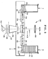
- Figure 3 is a schematic view of a slide reader having the carrier;
- Figure 4 is a schematic view illustrating a structure in the carrier;
- Figure 5 is a cross-sectional view of a withdraw cartridge illustrating a situation of slide mounts piling up therein;
- Figure 6 is a cross-sectional view of the withdraw cartridge when the slide mount is inserted into it;
- Figure 7 is a cross-sectional view of the withdraw cartridge, illustrating a state that the slide mount contacts to a guide roller.
-
- In FIG. 1, a
slide mount 2 hasopenings 3 and 4 in which asupply cartridge 6 and awithdraw cartridge 7 are set respectively. In thesupply cartridge 6,slide mounts 10 andsort cards 11 are loaded. As already known, theslide mount 10 has a structure that a positive film is sandwitched between tetragonal frame sheets. Thesort card 11 is a tetragonal plate and has detection holes representing a sorting information. Each of theslide mount 10 and thesort card 11 is fed from thesupply cartridge 6 through an inside of themount carrier 2 to thewithdraw cartridge 7. Thesort card 11 is used for sorting theme, customer or the like of theslide mount 10. - In the
mount carrier 2, a read-out aperture 8 is formed between theopening 3 and the opening 4, and used for reading out an image of theslide mount 10. When theslide mount 10 is disposed in a reading station, an image of theslide mount 10 is read out through the read-out aperture 8. - As shown in FIG. 2, the
supply cartridge 6 is constructed of acartridge body 12 and alid 13. Thecartridge body 12 is formed of a transparent synthetic resin and has a rectangular shaped shell such that theslide mounts 10 andsort card 11 may be piled up. To an upper side of thecartridge body 12, alid 13 is attached through ahinge 14 and moves between an open position and a close position. In the open position, a side and a top of thecartridge body 12 are open for easily inserting or removing theslide mount 10. - In a lower side of the
cartridge body 12, aninlet 17 is formed, and on a bottom of thecartridge body 12, amount supporter 15 and anopening 16 is formed. Themount supporter 15 supports the lowest one ofslide mounts 10 piling in thecartridge body 12 such that theslide mounts 10 may not fall from thecartridge body 12. The opening 16 is surrounded with themount supporter 15. Further, thewithdraw cartridge 7 has a same structure as thesupply cartridge 6, and used as the withdrawcartridge 7 after becoming empty. - In FIG. 3, in the
carrier 2, there are a pull outlever 21, afirst feed section 22, amovable stage 23, asecond feed section 24 and adrawing roller 25 which is made of rubber and rotated by a motor (not shown). - The pull out
lever 21 is disposed in theopening 3 so as to enter through the opening 16 in thesupply cartridge 6. The pull outlever 21 has acraw portion 21a which engages to a rear edge of the lowest one of theslide mounts 10. The pull outlever 21 is slid in a feed direction A and in a return direction B by a cam mechanism (not shown). When the pull outlever 21 is slid in the feed direction A, theslide mount 10 is pushed out toward thefirst feed section 22. - The
first feed section 22 is provided with feed-roller pairs 35. By rotation of the feed-roller pair 35, theslide mount 10 is fed from thefirst feed section 22 to a movingstage 23 which slides in the feed direction A and in the return direction B. On themovable stage 23 theslide mount 10 is fixed at set position. - Above and below the
movable stage 23, aline scanner 20 is provided for reading out an image of theslide mount 10. Theline scanner 20 has alight source 54, anIR cut filter 55, a lightamount adjusting plate 56, afilter 57, alight diffusing box 58 and a diffusingplate 59 below themovable stage 23. Above themovable stage 23, alens unit 60 and aCCD line sensor 61 are disposed. - The
line scanner 20 read out the image of theslide mount 10 at the set position on themovable stage 23, synchronized with the moving of themovable stage 23 in the feeding direction A (main-scanning direction). In order to read out the image, thelight source 54 emits a light. The light passes through the IR cutfilter 55, the lightamount adjusting plate 56 and thefilter 57 to enter into thelight diffusing box 58. In thelight diffusing box 58, an intensity distribution of the light is made so as to be uniform. After the light exits from thelight diffusing box 58, the light passes through the diffusingplate 59 to perform more uniform. Then a part of the light passes in the slit provided for themovable stage 23, and passes through theslide mount 10. Thereafter, thelens unit 60 focuses the light onto theCCD line sensor 61. When receiving the part of the light which has been passed through theslide mount 10, theCCD line sensor 61 generates an image signals. The processing of the image is carried out in a known method by an image processor, and the image is printed with a digital printer (not shown). Note that there are two sorts of the balance filters 57, for a negative film and a positive film. Each of the balance filters 57 is selected in accordance with whether theslide mount 10 has a positive film or a negative film, to perform a color correction. - After reading the image by the
line scanner 20, theslide mount 10 is transported into thesecond feed section 24. Thesecond feed section 24 is provided with feed-roller pairs 64, and the feed-roller pair 64 is rotated to feed theslide mount 10 to the withdrawcartridge 7. The drawingroller 25 disposed in the opening 4 in order to enter through theopening 16 when the withdrawcartridge 7 is attached. - Near to the
aperture 17 outside of the withdrawcartridge 7, aguide roller 70 is provided so as to rotate free. Theguide roller 70 is formed of rubber or plastics. While theslide mount 10 is drawn into the withdrawcartridge 7 by rotation of the drawingroller 25, theguide roller 70 contacts to the rear end of theslide mount 10 such that the rear end may not be heap up so much. - In FIG. 4, the pull out
lever 21 is driven through a clutch 30 by amotor 31. Note that theindication 32 is a driver for themotor 31. - In the
first feed section 22, theslide mount 10 is nipped by three of the feed roller pairs 35 which are biased bysprings 37. The feed-roller pairs 35 are rotated by themotor 31. Further, in the first feed section 22 a mount sensor 36 is disposed for detect edges of theslide mount 10 and thesort card 11 that are fed by rotation of the feed-roller pairs 35. Corresponding to detecting the edge, the mount sensor 36 generates a detect signal and outputs it to thecontroller 37. Thus, a position of theslide mount 10 can be acknowledged of thecontroller 37. Further, the mount sensor 36 detects a discrimination hole of thesort card 11 in order to distinguish theslide mount 10 and thesort card 11. - The
movable stage 23 is constituted of astage body 40, two feed-roller pairs 41, astage moving mechanism 42, amount sensor 36b, andpositioning projections stage moving mechanism 42 is constituted of ascan motor 48 and afeed screw 49. In thestage moving mechanism 42, thescan motor 48 rotates thefeed screw 49 in normal and reverse directions, and the rotation is transformed into slide movement of thestage body 40. Thus thestage body 40 slides between a receive position for receiving the slide mount 10 from thefirst feed section 22 and a delivery position for delivering theslide mount 10 to thesecond feed section 24. - The feed roller pairs 41 are biased by
springs 47 to nip theslide mount 10, and rotated by a motor (not shown) to feed theslide mount 10 to the set position on themovable stage 23. When theslide mount 10 reaches to the set position, the edge of theslide mount 10 is detected by the mount sensor 37b. Thereby the mount sensor 37b generates a detection signal and send it to thecontroller 51. Thecontroller 51 stops the feed roller pairs rotating and controls thepositioning projections slide mount 10 at the set position. - When the
controller 37 discriminates, in response with the detect signal sent from themount sensor 36a, that thesort card 11 is fed on themovable stage 23, even though themount sensor 36b detects the edge of thesort card 11, thecontroller 37 does not stop rotating the feed-roller pairs 41, and thesort card 11 continues to be fed. - After setting the
slide mount 10 to the set position, thestage body 40 slides further in a feed direction A, and thereby the pre-scanning is carried out. Then thestage body 40 slides in the return direction B, during which thestage body 40 stops once in order to carry out auto focusing. Thereafter thestage body 40 slides in the feed direction A again to carry out fine scanning. The pre-scanning and the fine-scanning are carried out by driving theline scanner 20 synchronized with the slide of themovable stage 23. Note that thenumber 51 is a driver for ascanning motor 48. - In the
second feed section 24 the three feed-roller pairs 64 is biased bysprings 67 to nip the slide mount 10 from themovable stage 23 and rotate to feed it in the feed direction A. In order to feed theslide mount 10 into the withdrawcartridge 7, themotor 65 drives the drawingroller 25 to rotate. Note that thenumber 66 is a driver for themotor 65. - Effects of the above embodiments will be described now. As shown in FIG. 5, after the fine-scanning, the
slide mount 10 is fed to the withdrawcartridge 7 by the feed-roller pairs 64, and drawn through theinlet 17 into the withdrawcartridge 7. Thereby, as shown in FIG. 6, the front end of theslide mount 10 is ridden up on the periphery of the drawingroller 25. After the front end of theslide mount 10 leaves theguide roller 25, the front end is guided to another slide mount located at lowermost in the withdraw cartridge 4. Therefore, the rear end of the slide mount 10 lifts gradually. - Thus, as shown in FIG. 7, the rear end contacts to the
guide roller 70, and theslide mount 10 is held by the drawingroller 25 and theguide roller 70. While theslide mount 10, due to rotation of drawingroller 25, is drawn into the withdrawncartridge 7, the front end of theslide mount 10 does not contact to themount supporter 15, and keeps at a constant angle to the feeding direction A. Accordingly, the front end of theslide mount 10 which enters into the withdrawcartridge 7 is not caught by the edge of the frame of another slide mount 10 located at lowermost. When the front end of theslide mount 10 leaves theguide roller 70, the lower end falls to contact to themount supporter 15. - Various changes and modifications are possible in the present invention and may be understood to be within the present invention.
Claims (4)
- A slide mount loading device for piling up slide mounts (10) in a slide mount cartridge (7), said cartridge (7) having an inlet (17) formed in a lower part of said cartridge (7), and an opening (16) being formed on a bottom of said cartridge (7), said slide mount loading device comprising:a drawing roller (25) provided so as to enter in said opening (16) of said cartridge (7), said drawing roller (25) inserting said slide mount (10) through said inlet (17) in said cartridge (7); anda slide mount contact member (70) provided near to said inlet (17) outside of said cartridge (7), said slide mount contact member (70) restricting to lift a rear end of said slide mount (10) such that said slide mount (10) may be inserted in said cartridge (7) with keeping an angle constant.
- A slide mount loading device as claimed in claim 1, wherein said slide mount contact member (70) is a roller (70).
- A slide mount loading device as claimed in claim 2, wherein said cartridge (7) includes a cartridge body (12), and said angle of said slide mount (10) is determined such that a front end of said slide mount (10) may not contact to said bottom of said cartridge body (12).
- A slide mount loading device as claimed in claim 3, wherein said cartridge (7) further includes a lid (13) which is openably attached to said cartridge body (12), and said inlet (17) is formed between said cartridge body (12) and said lid (13).
Applications Claiming Priority (2)
| Application Number | Priority Date | Filing Date | Title |
|---|---|---|---|
| JP2001273148 | 2001-09-10 | ||
| JP2001273148A JP2003084375A (en) | 2001-09-10 | 2001-09-10 | Slide mount stacking device |
Publications (2)
| Publication Number | Publication Date |
|---|---|
| EP1291710A1 true EP1291710A1 (en) | 2003-03-12 |
| EP1291710B1 EP1291710B1 (en) | 2005-05-25 |
Family
ID=19098404
Family Applications (1)
| Application Number | Title | Priority Date | Filing Date |
|---|---|---|---|
| EP02019862A Expired - Lifetime EP1291710B1 (en) | 2001-09-10 | 2002-09-09 | Slide mount loading device |
Country Status (3)
| Country | Link |
|---|---|
| EP (1) | EP1291710B1 (en) |
| JP (1) | JP2003084375A (en) |
| DE (1) | DE60204267T2 (en) |
Citations (4)
| Publication number | Priority date | Publication date | Assignee | Title |
|---|---|---|---|---|
| US2649093A (en) * | 1951-03-21 | 1953-08-18 | Joseph W Rigney | Slide container |
| US3974626A (en) * | 1975-09-09 | 1976-08-17 | Pako Corporation | Slide cassette packer |
| US4237678A (en) * | 1978-03-06 | 1980-12-09 | Forox Corporation | Apparatus for loading film transparencies into pre-closed slide mounts |
| FR2659152A1 (en) * | 1990-03-05 | 1991-09-06 | Lepetit Guy | Apparatus making it possible to place slides in slide projector cassettes |
Family Cites Families (1)
| Publication number | Priority date | Publication date | Assignee | Title |
|---|---|---|---|---|
| US5949524A (en) * | 1997-07-18 | 1999-09-07 | Eastman Kodak Company | Film segment printing system and method |
-
2001
- 2001-09-10 JP JP2001273148A patent/JP2003084375A/en active Pending
-
2002
- 2002-09-09 EP EP02019862A patent/EP1291710B1/en not_active Expired - Lifetime
- 2002-09-09 DE DE2002604267 patent/DE60204267T2/en not_active Expired - Lifetime
Patent Citations (4)
| Publication number | Priority date | Publication date | Assignee | Title |
|---|---|---|---|---|
| US2649093A (en) * | 1951-03-21 | 1953-08-18 | Joseph W Rigney | Slide container |
| US3974626A (en) * | 1975-09-09 | 1976-08-17 | Pako Corporation | Slide cassette packer |
| US4237678A (en) * | 1978-03-06 | 1980-12-09 | Forox Corporation | Apparatus for loading film transparencies into pre-closed slide mounts |
| FR2659152A1 (en) * | 1990-03-05 | 1991-09-06 | Lepetit Guy | Apparatus making it possible to place slides in slide projector cassettes |
Also Published As
| Publication number | Publication date |
|---|---|
| DE60204267T2 (en) | 2006-03-23 |
| DE60204267D1 (en) | 2005-06-30 |
| EP1291710B1 (en) | 2005-05-25 |
| JP2003084375A (en) | 2003-03-19 |
Similar Documents
| Publication | Publication Date | Title |
|---|---|---|
| CA2174274C (en) | Separating document trays imaging system | |
| US10142502B2 (en) | Image reading apparatus and image forming apparatus including storage which stores information relating to sheet size detected by size detector | |
| US5377966A (en) | Automatic document feeder | |
| US6738167B1 (en) | Image reading apparatus and document feeding method in image reading apparatus | |
| US5973729A (en) | Image input device capable of identifying different adaptors inserted into the input device | |
| CN101663883B (en) | Discerning between original media and blank media in a common feed path printer device | |
| JP2002148728A (en) | Slide mount supply equipment and film carrier | |
| US20060110197A1 (en) | Automatic document transportation device | |
| EP1291710B1 (en) | Slide mount loading device | |
| US6906831B2 (en) | Scanner device having a sheet handling path with a reduced bending angle | |
| US20170339292A1 (en) | Image reading apparatus and image forming apparatus | |
| US6542262B1 (en) | Scanner device and control method thereof, and film feeding device | |
| US7261290B2 (en) | Small/special media guide-in tray | |
| KR20050077890A (en) | Image reading apparatus having auto doucument feeder | |
| JPH07203136A (en) | Original scanner | |
| US5751402A (en) | Microfilm cassette and microfilm camera | |
| JP2002362784A (en) | Document detecting device, document conveying device, image reading device, and image forming device | |
| JP2005045445A (en) | Automatic document feeder | |
| EP1267203A2 (en) | Slide scanner with means for separating the slides from a stack | |
| JP7629358B2 (en) | Media transport device | |
| EP1313304A2 (en) | Image reading apparatus | |
| JP2003152950A (en) | Original feeder and image reader | |
| EP1176797A2 (en) | Method and apparatus for scanning image, film carrier and sort card | |
| JPH03279140A (en) | Image reading device | |
| JPH0614139A (en) | Image reader |
Legal Events
| Date | Code | Title | Description |
|---|---|---|---|
| PUAI | Public reference made under article 153(3) epc to a published international application that has entered the european phase |
Free format text: ORIGINAL CODE: 0009012 |
|
| AK | Designated contracting states |
Kind code of ref document: A1 Designated state(s): AT BE BG CH CY CZ DE DK EE ES FI FR GB GR IE IT LI LU MC NL PT SE SK TR |
|
| AX | Request for extension of the european patent |
Extension state: AL LT LV MK RO SI |
|
| 17P | Request for examination filed |
Effective date: 20030410 |
|
| AKX | Designation fees paid |
Designated state(s): DE FR GB |
|
| 17Q | First examination report despatched |
Effective date: 20040512 |
|
| GRAP | Despatch of communication of intention to grant a patent |
Free format text: ORIGINAL CODE: EPIDOSNIGR1 |
|
| GRAS | Grant fee paid |
Free format text: ORIGINAL CODE: EPIDOSNIGR3 |
|
| GRAA | (expected) grant |
Free format text: ORIGINAL CODE: 0009210 |
|
| AK | Designated contracting states |
Kind code of ref document: B1 Designated state(s): DE FR GB |
|
| REG | Reference to a national code |
Ref country code: GB Ref legal event code: FG4D |
|
| REG | Reference to a national code |
Ref country code: IE Ref legal event code: FG4D |
|
| REF | Corresponds to: |
Ref document number: 60204267 Country of ref document: DE Date of ref document: 20050630 Kind code of ref document: P |
|
| ET | Fr: translation filed | ||
| PLBE | No opposition filed within time limit |
Free format text: ORIGINAL CODE: 0009261 |
|
| STAA | Information on the status of an ep patent application or granted ep patent |
Free format text: STATUS: NO OPPOSITION FILED WITHIN TIME LIMIT |
|
| 26N | No opposition filed |
Effective date: 20060228 |
|
| REG | Reference to a national code |
Ref country code: GB Ref legal event code: 732E |
|
| REG | Reference to a national code |
Ref country code: FR Ref legal event code: CD Ref country code: FR Ref legal event code: TP |
|
| PGFP | Annual fee paid to national office [announced via postgrant information from national office to epo] |
Ref country code: FR Payment date: 20110922 Year of fee payment: 10 Ref country code: GB Payment date: 20110907 Year of fee payment: 10 Ref country code: DE Payment date: 20110817 Year of fee payment: 10 |
|
| GBPC | Gb: european patent ceased through non-payment of renewal fee |
Effective date: 20120909 |
|
| REG | Reference to a national code |
Ref country code: FR Ref legal event code: ST Effective date: 20130531 |
|
| REG | Reference to a national code |
Ref country code: DE Ref legal event code: R119 Ref document number: 60204267 Country of ref document: DE Effective date: 20130403 |
|
| PG25 | Lapsed in a contracting state [announced via postgrant information from national office to epo] |
Ref country code: DE Free format text: LAPSE BECAUSE OF NON-PAYMENT OF DUE FEES Effective date: 20130403 Ref country code: GB Free format text: LAPSE BECAUSE OF NON-PAYMENT OF DUE FEES Effective date: 20120909 |
|
| PG25 | Lapsed in a contracting state [announced via postgrant information from national office to epo] |
Ref country code: FR Free format text: LAPSE BECAUSE OF NON-PAYMENT OF DUE FEES Effective date: 20121001 |