EP1291636B1 - Modular surface-mount fluid-flow system - Google Patents
Modular surface-mount fluid-flow system Download PDFInfo
- Publication number
- EP1291636B1 EP1291636B1 EP20020019611 EP02019611A EP1291636B1 EP 1291636 B1 EP1291636 B1 EP 1291636B1 EP 20020019611 EP20020019611 EP 20020019611 EP 02019611 A EP02019611 A EP 02019611A EP 1291636 B1 EP1291636 B1 EP 1291636B1
- Authority
- EP
- European Patent Office
- Prior art keywords
- fluid
- stick
- flow
- block
- passages
- Prior art date
- Legal status (The legal status is an assumption and is not a legal conclusion. Google has not performed a legal analysis and makes no representation as to the accuracy of the status listed.)
- Expired - Lifetime
Links
- 239000012530 fluid Substances 0.000 claims description 98
- 238000004891 communication Methods 0.000 claims description 24
- 238000013459 approach Methods 0.000 description 14
- 238000004458 analytical method Methods 0.000 description 8
- 238000004519 manufacturing process Methods 0.000 description 8
- 238000000034 method Methods 0.000 description 7
- 238000012864 cross contamination Methods 0.000 description 6
- 238000005070 sampling Methods 0.000 description 6
- 230000008901 benefit Effects 0.000 description 4
- 238000009434 installation Methods 0.000 description 4
- 238000012423 maintenance Methods 0.000 description 4
- 230000008569 process Effects 0.000 description 4
- 238000009529 body temperature measurement Methods 0.000 description 3
- 238000013461 design Methods 0.000 description 2
- 238000003754 machining Methods 0.000 description 2
- 238000012986 modification Methods 0.000 description 2
- 230000004048 modification Effects 0.000 description 2
- 229910000619 316 stainless steel Inorganic materials 0.000 description 1
- 230000002411 adverse Effects 0.000 description 1
- 238000005219 brazing Methods 0.000 description 1
- 230000008859 change Effects 0.000 description 1
- 229920001971 elastomer Polymers 0.000 description 1
- 239000000806 elastomer Substances 0.000 description 1
- 238000005516 engineering process Methods 0.000 description 1
- NBVXSUQYWXRMNV-UHFFFAOYSA-N fluoromethane Chemical compound FC NBVXSUQYWXRMNV-UHFFFAOYSA-N 0.000 description 1
- 239000007788 liquid Substances 0.000 description 1
- 239000000463 material Substances 0.000 description 1
- 238000012544 monitoring process Methods 0.000 description 1
- 239000003348 petrochemical agent Substances 0.000 description 1
- -1 polytetrafluoroethylene Polymers 0.000 description 1
- 229920001343 polytetrafluoroethylene Polymers 0.000 description 1
- 239000004810 polytetrafluoroethylene Substances 0.000 description 1
- 238000004886 process control Methods 0.000 description 1
- 238000012545 processing Methods 0.000 description 1
- 230000008439 repair process Effects 0.000 description 1
- 238000003466 welding Methods 0.000 description 1
Images


Classifications
-
- F—MECHANICAL ENGINEERING; LIGHTING; HEATING; WEAPONS; BLASTING
- F16—ENGINEERING ELEMENTS AND UNITS; GENERAL MEASURES FOR PRODUCING AND MAINTAINING EFFECTIVE FUNCTIONING OF MACHINES OR INSTALLATIONS; THERMAL INSULATION IN GENERAL
- F16K—VALVES; TAPS; COCKS; ACTUATING-FLOATS; DEVICES FOR VENTING OR AERATING
- F16K27/00—Construction of housing; Use of materials therefor
- F16K27/003—Housing formed from a plurality of the same valve elements
-
- F—MECHANICAL ENGINEERING; LIGHTING; HEATING; WEAPONS; BLASTING
- F15—FLUID-PRESSURE ACTUATORS; HYDRAULICS OR PNEUMATICS IN GENERAL
- F15B—SYSTEMS ACTING BY MEANS OF FLUIDS IN GENERAL; FLUID-PRESSURE ACTUATORS, e.g. SERVOMOTORS; DETAILS OF FLUID-PRESSURE SYSTEMS, NOT OTHERWISE PROVIDED FOR
- F15B13/00—Details of servomotor systems ; Valves for servomotor systems
- F15B13/02—Fluid distribution or supply devices characterised by their adaptation to the control of servomotors
- F15B13/06—Fluid distribution or supply devices characterised by their adaptation to the control of servomotors for use with two or more servomotors
- F15B13/08—Assemblies of units, each for the control of a single servomotor only
- F15B13/0803—Modular units
- F15B13/0807—Manifolds
- F15B13/0817—Multiblock manifolds
-
- F—MECHANICAL ENGINEERING; LIGHTING; HEATING; WEAPONS; BLASTING
- F15—FLUID-PRESSURE ACTUATORS; HYDRAULICS OR PNEUMATICS IN GENERAL
- F15B—SYSTEMS ACTING BY MEANS OF FLUIDS IN GENERAL; FLUID-PRESSURE ACTUATORS, e.g. SERVOMOTORS; DETAILS OF FLUID-PRESSURE SYSTEMS, NOT OTHERWISE PROVIDED FOR
- F15B13/00—Details of servomotor systems ; Valves for servomotor systems
- F15B13/02—Fluid distribution or supply devices characterised by their adaptation to the control of servomotors
- F15B13/06—Fluid distribution or supply devices characterised by their adaptation to the control of servomotors for use with two or more servomotors
- F15B13/08—Assemblies of units, each for the control of a single servomotor only
- F15B13/0803—Modular units
- F15B13/0821—Attachment or sealing of modular units to each other
- F15B13/0825—Attachment or sealing of modular units to each other the modular elements being mounted on a common member, e.g. on a rail
-
- F—MECHANICAL ENGINEERING; LIGHTING; HEATING; WEAPONS; BLASTING
- F15—FLUID-PRESSURE ACTUATORS; HYDRAULICS OR PNEUMATICS IN GENERAL
- F15B—SYSTEMS ACTING BY MEANS OF FLUIDS IN GENERAL; FLUID-PRESSURE ACTUATORS, e.g. SERVOMOTORS; DETAILS OF FLUID-PRESSURE SYSTEMS, NOT OTHERWISE PROVIDED FOR
- F15B13/00—Details of servomotor systems ; Valves for servomotor systems
- F15B13/02—Fluid distribution or supply devices characterised by their adaptation to the control of servomotors
- F15B13/06—Fluid distribution or supply devices characterised by their adaptation to the control of servomotors for use with two or more servomotors
- F15B13/08—Assemblies of units, each for the control of a single servomotor only
- F15B13/0803—Modular units
- F15B13/0832—Modular valves
-
- F—MECHANICAL ENGINEERING; LIGHTING; HEATING; WEAPONS; BLASTING
- F15—FLUID-PRESSURE ACTUATORS; HYDRAULICS OR PNEUMATICS IN GENERAL
- F15B—SYSTEMS ACTING BY MEANS OF FLUIDS IN GENERAL; FLUID-PRESSURE ACTUATORS, e.g. SERVOMOTORS; DETAILS OF FLUID-PRESSURE SYSTEMS, NOT OTHERWISE PROVIDED FOR
- F15B13/00—Details of servomotor systems ; Valves for servomotor systems
- F15B13/02—Fluid distribution or supply devices characterised by their adaptation to the control of servomotors
- F15B13/06—Fluid distribution or supply devices characterised by their adaptation to the control of servomotors for use with two or more servomotors
- F15B13/08—Assemblies of units, each for the control of a single servomotor only
- F15B13/0803—Modular units
- F15B13/0846—Electrical details
- F15B13/086—Sensing means, e.g. pressure sensors
-
- F—MECHANICAL ENGINEERING; LIGHTING; HEATING; WEAPONS; BLASTING
- F15—FLUID-PRESSURE ACTUATORS; HYDRAULICS OR PNEUMATICS IN GENERAL
- F15B—SYSTEMS ACTING BY MEANS OF FLUIDS IN GENERAL; FLUID-PRESSURE ACTUATORS, e.g. SERVOMOTORS; DETAILS OF FLUID-PRESSURE SYSTEMS, NOT OTHERWISE PROVIDED FOR
- F15B13/00—Details of servomotor systems ; Valves for servomotor systems
- F15B13/02—Fluid distribution or supply devices characterised by their adaptation to the control of servomotors
- F15B13/06—Fluid distribution or supply devices characterised by their adaptation to the control of servomotors for use with two or more servomotors
- F15B13/08—Assemblies of units, each for the control of a single servomotor only
- F15B13/0803—Modular units
- F15B13/0875—Channels for electrical components, e.g. for cables or sensors
-
- F—MECHANICAL ENGINEERING; LIGHTING; HEATING; WEAPONS; BLASTING
- F15—FLUID-PRESSURE ACTUATORS; HYDRAULICS OR PNEUMATICS IN GENERAL
- F15B—SYSTEMS ACTING BY MEANS OF FLUIDS IN GENERAL; FLUID-PRESSURE ACTUATORS, e.g. SERVOMOTORS; DETAILS OF FLUID-PRESSURE SYSTEMS, NOT OTHERWISE PROVIDED FOR
- F15B13/00—Details of servomotor systems ; Valves for servomotor systems
- F15B13/02—Fluid distribution or supply devices characterised by their adaptation to the control of servomotors
- F15B13/06—Fluid distribution or supply devices characterised by their adaptation to the control of servomotors for use with two or more servomotors
- F15B13/08—Assemblies of units, each for the control of a single servomotor only
- F15B13/0803—Modular units
- F15B13/0878—Assembly of modular units
- F15B13/0885—Assembly of modular units using valves combined with other components
- F15B13/0892—Valves combined with fluid components
-
- F—MECHANICAL ENGINEERING; LIGHTING; HEATING; WEAPONS; BLASTING
- F15—FLUID-PRESSURE ACTUATORS; HYDRAULICS OR PNEUMATICS IN GENERAL
- F15B—SYSTEMS ACTING BY MEANS OF FLUIDS IN GENERAL; FLUID-PRESSURE ACTUATORS, e.g. SERVOMOTORS; DETAILS OF FLUID-PRESSURE SYSTEMS, NOT OTHERWISE PROVIDED FOR
- F15B13/00—Details of servomotor systems ; Valves for servomotor systems
- F15B13/02—Fluid distribution or supply devices characterised by their adaptation to the control of servomotors
- F15B13/06—Fluid distribution or supply devices characterised by their adaptation to the control of servomotors for use with two or more servomotors
- F15B13/08—Assemblies of units, each for the control of a single servomotor only
- F15B13/0803—Modular units
- F15B13/0878—Assembly of modular units
- F15B13/0896—Assembly of modular units using different types or sizes of valves
-
- G—PHYSICS
- G01—MEASURING; TESTING
- G01N—INVESTIGATING OR ANALYSING MATERIALS BY DETERMINING THEIR CHEMICAL OR PHYSICAL PROPERTIES
- G01N35/00—Automatic analysis not limited to methods or materials provided for in any single one of groups G01N1/00 - G01N33/00; Handling materials therefor
- G01N2035/00178—Special arrangements of analysers
- G01N2035/00326—Analysers with modular structure
-
- Y—GENERAL TAGGING OF NEW TECHNOLOGICAL DEVELOPMENTS; GENERAL TAGGING OF CROSS-SECTIONAL TECHNOLOGIES SPANNING OVER SEVERAL SECTIONS OF THE IPC; TECHNICAL SUBJECTS COVERED BY FORMER USPC CROSS-REFERENCE ART COLLECTIONS [XRACs] AND DIGESTS
- Y10—TECHNICAL SUBJECTS COVERED BY FORMER USPC
- Y10T—TECHNICAL SUBJECTS COVERED BY FORMER US CLASSIFICATION
- Y10T137/00—Fluid handling
- Y10T137/5109—Convertible
-
- Y—GENERAL TAGGING OF NEW TECHNOLOGICAL DEVELOPMENTS; GENERAL TAGGING OF CROSS-SECTIONAL TECHNOLOGIES SPANNING OVER SEVERAL SECTIONS OF THE IPC; TECHNICAL SUBJECTS COVERED BY FORMER USPC CROSS-REFERENCE ART COLLECTIONS [XRACs] AND DIGESTS
- Y10—TECHNICAL SUBJECTS COVERED BY FORMER USPC
- Y10T—TECHNICAL SUBJECTS COVERED BY FORMER US CLASSIFICATION
- Y10T137/00—Fluid handling
- Y10T137/8593—Systems
- Y10T137/877—With flow control means for branched passages
- Y10T137/87885—Sectional block structure
Definitions
- This invention relates to a surface-mount fluid-flow system and, more particularly, to a fluid sampling system.
- a continuous flow of a fluid is periodically sampled and analyzed by an automated sampling-and-analysis system.
- the results of the analysis are used to control process operating parameters through a feedback control system.
- the present invention is concerned with the sampling and fluid control apparatus, rather than the analysis apparatus or the feedback control system.
- valves, regulators, gauges, flow indicators, and other fluid components are linked together to provide a sample of the process fluid flow to the analyzer and then to return the sample back to the process flow.
- the earliest sampling and analysis systems used conventional discrete fluid components linked by piping. These systems extract a relatively large volume of fluid in each sample, and the distances that the fluid must flow through the system are relatively large. Consequently, the sampling lag time is relatively long, which is undesirable from the standpoint of achieving good process control.
- These discrete-component systems have relatively high installed cost and maintenance cost.
- the volume of fluid in the sample and the flow distance may be reduced by miniaturizing the system.
- the fluid components are reduced in size as much as possible,
- the miniature fluid components are mounted to a surface of a support structure that provides both mechanical support for the fluid components and also mechanical and fluid interconnection between the fluid components.
- This surface-mount fluid-flow system has the potential to reduce installed cost and maintenance cost for flow sampling, and a number of surface-mount systems have been proposed,
- the available systems have a number of shortcomings. Most installations are one-of-a-kind or require only a few of the same type of sampling-and-analysis systems, so that most installations are of a custom or semi-custom type.
- the available systems typically involve a large number of components, and/or expensive custom machining of components for each installation, and/or high assembly costs.
- the design procedures are also complex. Additionally, in some systems there is a potential for cross contamination between fluid streams within the apparatus, of a type that cannot be readily detected.
- the present invention provides an approach and apparatus for controlling fluid flows using a surface-mount technology. It uses a small number of different types of standardized elements to build complex systems, making the design, fabrication, assembly, and installation of fluid-flow systems relatively inexpensive. Maintenance costs are also relatively low.
- the present approach is therefore particularly well suited for sampling-and-analysis systems such as used in fluid process industries. The potential for undetected leakage and cross contamination is greatly reduced as compared with prior approaches.
- a fluid-flow system comprises a first stick.
- the first stick has a first plurality of substantially identical stick blocks.
- Each stick block is a plate having a front face, a back face, an edge face, and at least two fluid-flow through-passages extending between the front face and the back face.
- the stick blocks are attached to each other by a first-stick-block attachment including a fastener that extends through an attachment bore, the attachment bore extending through a first step and a second step when the first step and the second step are conformably positioned.
- the stick includes at least one fluid component affixed to the front face of each of the plurality of stick blocks.
- Each fluid component (48) has ports thereon, with the ports of each fluid component being in fluid communication with the respective fluid-flow through-passages of the stick block to which it is affixed.
- Each first-stick fluid-flow block-interconnection tube is affixed to the back face of a first stick block with a first end of the fluid-flow block-interconnection tube in fluid communication with one of the fluid-flow through-passages on the first stick block, and also affixed to the back face of a second stick block with a second end of the fluid-flow block-interconnection tube in fluid communication with one of the fluid-flow through-passages on the second stick block.
- the fluid handled by the present approach may be a liquid or a gas.
- the stick blocks are connected together in a linear array to form a stick.
- the through-passages in each stick block all lie along a single line extending between two opposite ends of the stick block, parallel to the linear array where a linear array is used.
- the fluid-flow system may further include a mounting plate, and a set of mounting feet affixing the stick blocks to the mounting plate.
- the adapter plate has fluid-flow passages therethrough providing fluid communication between one of the ports on the fluid component and one of the fluid-flow through passages of the respective stick block, and may also provide other capabilities such as a heater to heat the fluid passing therethrough.
- the fluid-flow system also may include a second stick comprising a plurality of substantially identical stick blocks, the stick blocks being connected to each other along their edge faces, forming the second stick.
- Each fluid component has ports thereon, the ports of each fluid component are in fluid communication with the respective fluid-flow through-passages of the stick block of the second stick to which it is affixed.
- a plurality of stick fluid-flow block-interconnection tubes are external to the stick blocks of the second stick fluid-flow block-interconnection tube being affixed to the back face of a stick block of the second stick with a first end of the fluid-flow block-interconnection tube in fluid communication with one of the fluid-flow through-passages on the stick block of the second stick and also affixed to the back face of a second stick block of the second stick with a second end of the fluid-flow block-interconnection tube in fluid communication with one of the fluid-flow through-passages on the second stick block of the second stick.
- the present approach emphasizes good manufacturability and low cost of custom fluid-flow systems such as fluid-flow sampling systems.
- Each block has only holes and bores in its through-thickness direction, which are easily drilled with good precision. No holes or bores parallel to the front and back faces are used.
- the rectilinear "pegboard" character of the mounting holes of the preferred mounting plate which are aligned with comparable holes in the blocks, allows complex systems to be arranged and assembled rapidly and with no specialized fabrication procedures or tools applied. No custom machining is required for each stick. This structural simplicity translates to low labor requirements for the assembler and minimal chances of error.
- the present approach provides excellent technical capability.
- the general surface-mount architecture is used, and industry standards such as SP 76 are followed.
- the interconnection tubes are open and visible. Leaks in the interconnection tubes and their attachments and seals are unlikely. However, if leaks do occur they are openly visible and readily repaired. If it is necessary to remove and replace or otherwise alter a block or a fluid-flow interconnection in the middle of a stick, these changes may be performed only with operations carried out at the block itself, and disassembly of the remainder of the system is not required. Further, there is no chance of cross contamination between two interconnection tubes and particularly no chance of cross contamination that goes undetected and therefore adversely influences the analytic results or the content of the fluid flows. The possibility of undetected leaks and the possibility of cross contamination are shortcomings with other architectures of fluid-flow systems.
- the present approach therefore provides for a fluid-flow system that has low initial (capital) costs and low maintenance costs.
- the fluid-flow system is also highly reliable and, if repairs or changes are necessary, easy to alter.
- Figure 1 is a schematic elevational view of a first stick of a fluid-flow system
- Figure 2 is a schematic plan view of the first stick of Figure 1 ;
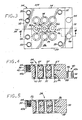
- Figure 3 is a plan view of a block used in the fluid flow system
- Figure 4 is a sectional view of the block of Figure 3 , taken along line 4-4, illustrating a mid-stick block;
- Figure 5 is a sectional view like that of Figure 3 , except illustrating an end-stick block
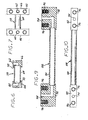
- Figure 6 is a schematic sectional view of a fluid-flow block interconnection tube
- Figure 7 is a schematic plan view of the fluid-flow block interconnection tube of Figure 6 ;
- Figure 8 is a schematic bottom view of a multi-stick fluid-flow system
- Figure 9 is a schematic sectional view of a stick-to-stick interconnection tube.
- Figure 10 is a schematic plan view of the stick-to-stick interconnection tube of Figure 9 .
- Figures 1 and 2 depict a fluid-flow system 20 comprising a first stick 22.
- the term "stick” is a term of art applying to an interconnected array of "blocks” (usually linear in nature) and their fluid components and fluid-flow interconnections, which will be described subsequently.
- the stick 22 includes a first plurality of substantially identical first-stick blocks 24.
- each block 24 has a front face 26, a back face 28, and an edge surface 30.
- each block 24 is in the form of a rectangular plate as illustrated, so that there are first pair of oppositely disposed edge faces 32 and a second pair of oppositely disposed edge faces 34.
- the three fluid-flow through-passages 36 include a center fluid-flow through passage 36a and two outer fluid-flow through-passages 36b.
- the three fluid-flow through-passages 36 lie along a stick axis 38 extending between the first pair of oppositely disposed edge faces 32 at a point midway between the second pair of oppositely disposed edge faces 34.
- the first-stick blocks 24 are attached to each other in a linear array oriented along the stick axis 38 at their first pairs of oppositely disposed edge faces 32 by a block attachment 40.
- the block attachment 40 preferably comprises a conformable step 42 on each block 24 of an attached pair of blocks 24.
- Conformable means that the steps of two adjacent blocks 24 mechanically interface with each other so as to allow attachment therebetween.
- one of the steps 42a is on the side of the block 24 that includes the front face 26, and the other of the steps 42b is on the side of the block 24 that includes the back face 28.
- An aligned attachment bore 44 extends through the conformable steps 42a and 42b so that the portion of the attachment bore 44 within step 42a aligns with the portion of the attachment bore 44 that is within step 42b when two adjacent blocks 24 are affixed together as shown in Figure 1 .
- a fastener 46 such as a screw or bolt extends through the attachment bore 44 and joins the two adjacent blocks 24 together.
- one end (here the end that is within the step 42a) of the attachment bore 44 may be threaded, and the fastener 46 is a bolt or screw that engages the threads from the other end (here the end that is within the step 42b) of the attachment bore 44.
- This type of block attachment 40 allows the attachment to be completed from either the front face 26 or the back face 28 during the assembly of blocks.
- the block 24 is designed so that only one configuration of block 24 is required to build up a fluid-flow system 20. However, if only the type of block 24 shown in Figure 4 is used, there is a step 42b extending out of one end of the stick 22, the right end in the view of Figure 1 . To square off the ends of the sticks 22, blocks 24 of the type shown in Figure 5 are used at the appropriate ends of the sticks 22.
- Figure 5 shows an end stick block with the step 42a at one end and the flat, squared-off surface 30 at the other end. However, the end block is otherwise identical to the mid-stick block shown in Figure 4 .
- At least one, and typically exactly one, fluid component 48 is affixed to the front face 26 of each of the plurality of first-stick blocks 24. (This is the origin of the term "surface-mount" to describe the present architecture. All of the fluid components 48 are installed to the surface of the same front face 26 of the respective blocks 24.)
- the fluid components 48 include any component that is required in the fluid monitoring or control system. Examples of such fluid components 48 are valves of different types, flowmeters, filters, heaters, pressure transducers, pressure regulators, flow controllers, temperature sensors, instruments, analyzers, and the like. The structure and operation of the individual fluid components are known in the art and are not within the scope of the present invention.
- the fluid components 48 are affixed to the respective blocks 24 by fasteners, preferably male-threaded fasteners, that engage the fluid components 48 and fluid-component attachment bores 50, which are preferably threaded with a female thread matching that of the fastener, extending downwardly from the front face 26 into the blocks 24.
- fasteners preferably male-threaded fasteners
- fluid-component attachment bores 50 which are preferably threaded with a female thread matching that of the fastener, extending downwardly from the front face 26 into the blocks 24.
- the mechanical connections between the blocks 24 and the fluid components 48 at the fluid-component attachment bores 50 are preferably made to conform to the mounting provisions of SEMI 2787.1 and ISA Draft Specification SP76.00.03 (termed "SP76" in the industry) which set forth, among other things, the arrangement of ports, physical envelope constraints, mounting hole locations and sizes, and the like for surface-mounted fluid-control systems.
- SP76 ISA Draft Specification
- a virtue of the present approach is that, if such specifications change in the future or other specifications are adopted, the block 24 and other mechanical components of the present approach may be readily adapted to such new specifications.
- Each fluid component 48 has ports 52 thereon, through which fluid flows into or out of the fluid component.
- the ports 52 of each fluid component 48 are in fluid communication with one of the respective fluid-flow through-passages 36 of the block 24 to which it is affixed, as shown in Figure 1 .
- the fluid communication between the ports 52 and the fluid-flow through passage 36 may be direct, as shown for the leftmost and rightmost fluid components 48 in Figure 1 .
- the adapter plate 54 may instead be an adapter plate 54 disposed between the fluid component 48 and the respective block 24 to which it is affixed, as seen for the center block 24 in Figure 1 .
- the adapter plate 54 has adapter-plate fluid-flow passages 56 therethrough providing fluid communication between one of the ports 52 on the fluid component 48 and one of the fluid-flow through passages 36 of the respective block 24.
- the adapter plate 54 thus allows a different port pattern of the fluid component 48 to be adapted to the standard pattern of the fluid-flow through passages 36 in the block 24.
- the adapter plate 54 may have other functions as well in performing as an auxiliary active device.
- Such auxiliary active device functions 55 include, for example, temperature measurement and/or control and flow direction and/or control.
- Examples of temperature measurement and/or control include a heater, a cooler, and a temperature measurement device such as a thermocouple within the adapter plate 54.
- Examples of flow direction and/or control include a check valve and an orifice in the flow channel within the adapter plate 54.
- an electrical resistance heater represented by embedded insulated resistance wires, is built into the adapter plate 54 and powered by current from an external source (not shown).
- the fluid connections between the ports 52 of the fluid component 48 and the fluid-flow through passages 36 are sealed with annular seals 57.
- the seals 57 preferably reside in recesses in the block 24 or the adapter plate 54, as appropriate.
- the seals 57 may be polymeric (for example, polytetrafluoroethylene), elastomeric (for example, a fluorocarbon such as VitonTM or KalrezTM elastomer), or metallic, according to the type of fluid being processed.
- the polymeric or elastomeric seals are presently preferred.
- the blocks 24 do not provide within themselves for the direct flow of fluid between the blocks, as for example a direct block-to-block fluid flow through sealed bores in the edge surfaces 30.
- Such fluid flow interconnection techniques result in an increased likelihood of undetected leakages and particularly cross contamination of fluid flows as a result of undetected leakages.
- the present approach provides for a second plurality of fluid-flow block-interconnection tubes 58 external to the blocks 24.
- the fluid-flow block-interconnection tube 58 which is shown in Figures 6-7 , is affixed to the back face 28 of a first block, such as a block 48a in Figure 1 , with a first end 60 of the fluid-flow block-interconnection tube 58 in fluid communication with one of the fluid-flow through-passages 36 on the first block 48.
- the fluid-flow block-interconnection tube 58 is also affixed to the back face 28 of a second block, such as a block 48b in Figure 2 , with a second end 62 of the fluid-flow block-interconnection tube 58 in fluid communication with one of the fluid-flow through-passages 36 on the second block 48b.
- a second block such as a block 48b in Figure 2
- at least one interconnection tube 58 extends between the block 48b and the block 48c in Figure 1 .
- each block interconnection tube 58 includes a tube 64 and a fitting 66 at each end 60 and 62.
- the tube 64 is brazed or welded to the fitting 66 at a joint 70.
- the back face 28 of the block 24 has seal recesses 67 that receives the annular seals 57 therein.
- the seal 57 seals the fluid-flow through passage 36 at its point of emergence from the back face 28 of the block 24 to the fitting 66.
- Each fitting 66 has two fitting attachment bores 72 therein, which align with corresponding fitting attachment bores 74 on the block 24.
- the fitting attachment bores 72 are preferably female threaded, so that a male-threaded fastener inserted from the front face 26 into the unthreaded fitting attachment bore 74 may be engaged to the threaded fitting attachment bores 72 to tighten the fitting 66 against the back face 28 of the block 24.
- An important advantage of the present approach is that only two lengths of block interconnection tubes 58 are required for virtually all applications.
- One length is required to extend between two adjacent outer fluid-flow through-passages 36b in neighboring blocks 24, as shown for the block interconnection tube 58 connecting blocks 24a and 24b in Figure 1
- a second length is required to extend between a center fluid-flow through-passage 36a and the outer fluid-flow through-passage 36b of neighboring blocks 24, as shown for the block interconnection tube 58 connecting blocks 24b and 24c in Figure 1 .
- External interconnections may be made using these two lengths.
- External connections to and from the stick 22 are made with external interconnection tubes 59 that are similar to the block interconnection tubes 58, except that they are attached to the blocks 24 at one end and to some external connection at the other.
- the external interconnection tubes 59 may be cantilevered, as illustrated in Figure 1 , or affixed to the block 24 or to the mounting plate discussed next to provide them rigid support. This use of a tubular external interconnection tube 59 allows a great deal of flexibility in making external connections. Fluid connections between sticks are made with fluid-flow stick-to-stick interconnections discussed subsequently.
- the fluid-flow system 20 further preferably includes a mounting plate 76 and a set of mounting feet 78 affixing the blocks 24 to the mounting plate 76.
- the mounting plate 76 desirably comprises a set of rectangularly arranged mounting holes 80 to which the mounting feet 78 are affixed. The fabrication of the fluid-flow system from the components is then accomplished by matching pre-existing holes and mounting structure.
- the mounting feet 78 are preferably in the form of L-shaped brackets whose lower end is fastened to the mounting holes 80 with fasteners such as screws or bolts, and whose upper end is affixed to the fitting attachment bore 74 either directly (as illustrated at the right-hand end of Figure 1 ) or as part of one of the fittings of the interconnection tubes discussed subsequently in relation to Figures 6-7 and 9-10 (as illustrated at the left-hand end of Figure 1 ).
- the stick 22 may be configured to perform any of a wide variety of functions, depending upon the selection of the fluid components 48 and the arrangements of the fluid-flow block interconnection tubes 58. In many types of fluid-flow systems 20, more-complex arrangements of the fluid-processing components are required. To achieve the higher complexity, multiple sticks 22 may be fabricated and mounted on the mounting plate 76 as illustrated in Figure 8 . In this case, three sticks 82, 84, and 86 are mounted to the mounting plate 76. The configuration of each stick 82, 84, and 86 is substantially as described earlier, except that the numbers of blocks, interconnections, and fluid components may be varied as necessary. In the illustration, stick 82 has 3 blocks, stick 84 has 6 blocks, and stick 86 has 5 blocks.
- Fluid interconnections between the sticks is made using a fluid-flow stick-to-stick interconnection tube 88 that extends between the sticks 82 and 84, or between the sticks 84 and 86, or between the sticks 82 and 86, as illustrated in Figure 8 .
- These fluid-flow stick-to-stick interconnection tubes 88 are oriented generally perpendicular to the fluid-flow block interconnection tubes 58. Alignment of the sticks and their interconnections is readily accomplished because of the rectilinear nature of the multi-stick structure achieved through the use of the mounting holes 80 in the mounting plate 76.
- the fluid-flow system of Figure 8 is not intended to relate to any particular system, but instead is presented as an illustration of some of the possible types of fluid-flow interconnections within and between sticks, and external to the sticks.
- the fluid-flow stick-to-stick interconnection 88 shown in detail in Figures 9-10 , is similar in structure to the fluid-flow block interconnection 58.
- a tube 90 is affixed by welding or brazing at each end to a respective fitting 92.
- the fitting 92 has a flow passage 94 that is aligned with one of the fluid-flow through passages 36 of the block 24.
- Fitting attachment bores 96 align with the fitting attachment bores 74 of the block 24, and fasteners (not shown) inserted into the fitting-attachment bores 74 fasten the fitting 92 to the block 24.
- the seals 57 are used to seal the fittings 92 to the block 24 in the manner discussed earlier.
- the components of the fluid-flow system 20 may be made of any operable material.
- the block 24 and the interconnection tubes are made of type 316 stainless steel.
Landscapes
- Engineering & Computer Science (AREA)
- General Engineering & Computer Science (AREA)
- Mechanical Engineering (AREA)
- Physics & Mathematics (AREA)
- Fluid Mechanics (AREA)
- Quick-Acting Or Multi-Walled Pipe Joints (AREA)
- Infusion, Injection, And Reservoir Apparatuses (AREA)
- Sampling And Sample Adjustment (AREA)
- Feeding, Discharge, Calcimining, Fusing, And Gas-Generation Devices (AREA)
Description
- This invention relates to a surface-mount fluid-flow system and, more particularly, to a fluid sampling system.
- In continuous fluid-flow manufacturing industries such as the production of petrochemicals, a continuous flow of a fluid is periodically sampled and analyzed by an automated sampling-and-analysis system. The results of the analysis are used to control process operating parameters through a feedback control system. The present invention is concerned with the sampling and fluid control apparatus, rather than the analysis apparatus or the feedback control system.
- In the sampling-and-analysis system, valves, regulators, gauges, flow indicators, and other fluid components are linked together to provide a sample of the process fluid flow to the analyzer and then to return the sample back to the process flow. The earliest sampling and analysis systems used conventional discrete fluid components linked by piping. These systems extract a relatively large volume of fluid in each sample, and the distances that the fluid must flow through the system are relatively large. Consequently, the sampling lag time is relatively long, which is undesirable from the standpoint of achieving good process control. These discrete-component systems have relatively high installed cost and maintenance cost.
- The volume of fluid in the sample and the flow distance may be reduced by miniaturizing the system. In one approach, the fluid components are reduced in size as much as possible, The miniature fluid components are mounted to a surface of a support structure that provides both mechanical support for the fluid components and also mechanical and fluid interconnection between the fluid components.
- This surface-mount fluid-flow system has the potential to reduce installed cost and maintenance cost for flow sampling, and a number of surface-mount systems have been proposed, However, the available systems have a number of shortcomings. Most installations are one-of-a-kind or require only a few of the same type of sampling-and-analysis systems, so that most installations are of a custom or semi-custom type. The available systems typically involve a large number of components, and/or expensive custom machining of components for each installation, and/or high assembly costs. The design procedures are also complex. Additionally, in some systems there is a potential for cross contamination between fluid streams within the apparatus, of a type that cannot be readily detected.
- There is a need for an improved fluid-flow system that overcomes these problems. Such a fluid-flow system is needed for the sampling-and-analysis field, and for other fields as well. The present invention fulfills this need, and further provides related advantages.
- The present invention provides an approach and apparatus for controlling fluid flows using a surface-mount technology. It uses a small number of different types of standardized elements to build complex systems, making the design, fabrication, assembly, and installation of fluid-flow systems relatively inexpensive. Maintenance costs are also relatively low. The present approach is therefore particularly well suited for sampling-and-analysis systems such as used in fluid process industries. The potential for undetected leakage and cross contamination is greatly reduced as compared with prior approaches.
- In accordance with the invention, a fluid-flow system comprises a first stick. The first stick has a first plurality of substantially identical stick blocks. Each stick block is a plate having a front face, a back face, an edge face, and at least two fluid-flow through-passages extending between the front face and the back face. The stick blocks are attached to each other by a first-stick-block attachment including a fastener that extends through an attachment bore, the attachment bore extending through a first step and a second step when the first step and the second step are conformably positioned. The stick includes at least one fluid component affixed to the front face of each of the plurality of stick blocks. Each fluid component (48) has ports thereon, with the ports of each fluid component being in fluid communication with the respective fluid-flow through-passages of the stick block to which it is affixed. There is a plurality of stick fluid-flow block-interconnection tubes external to the stick blocks. Each first-stick fluid-flow block-interconnection tube is affixed to the back face of a first stick block with a first end of the fluid-flow block-interconnection tube in fluid communication with one of the fluid-flow through-passages on the first stick block, and also affixed to the back face of a second stick block with a second end of the fluid-flow block-interconnection tube in fluid communication with one of the fluid-flow through-passages on the second stick block. The fluid handled by the present approach may be a liquid or a gas.
- In a preferred approach, the stick blocks are connected together in a linear array to form a stick. The through-passages in each stick block all lie along a single line extending between two opposite ends of the stick block, parallel to the linear array where a linear array is used. The fluid-flow system may further include a mounting plate, and a set of mounting feet affixing the stick blocks to the mounting plate. There may be an adapter plate disposed between one of the fluid components and the respective stick block to which it is affixed. The adapter plate has fluid-flow passages therethrough providing fluid communication between one of the ports on the fluid component and one of the fluid-flow through passages of the respective stick block, and may also provide other capabilities such as a heater to heat the fluid passing therethrough.
- The fluid-flow system also may include a second stick comprising a plurality of substantially identical stick blocks, the stick blocks being connected to each other along their edge faces, forming the second stick. There are at least one fluid component affixed to the front face of each of the plurality of stick blocks of the second stick. Each fluid component has ports thereon, the ports of each fluid component are in fluid communication with the respective fluid-flow through-passages of the stick block of the second stick to which it is affixed. A plurality of stick fluid-flow block-interconnection tubes are external to the stick blocks of the second stick fluid-flow block-interconnection tube being affixed to the back face of a stick block of the second stick with a first end of the fluid-flow block-interconnection tube in fluid communication with one of the fluid-flow through-passages on the stick block of the second stick and also affixed to the back face of a second stick block of the second stick with a second end of the fluid-flow block-interconnection tube in fluid communication with one of the fluid-flow through-passages on the second stick block of the second stick. There is a fluid interconnection between the first stick and the second stick.
- The present approach emphasizes good manufacturability and low cost of custom fluid-flow systems such as fluid-flow sampling systems. There is only one basic block type required, although modifications of the basic block type may be provided that do not have an end connector on one end and which are used as the end blocks of a stick. Each block has only holes and bores in its through-thickness direction, which are easily drilled with good precision. No holes or bores parallel to the front and back faces are used. There are only two basic lengths of intra-stick interconnection tubes required, so that only two such types of interconnection tubes need be fabricated and kept on hand. The rectilinear "pegboard" character of the mounting holes of the preferred mounting plate, which are aligned with comparable holes in the blocks, allows complex systems to be arranged and assembled rapidly and with no specialized fabrication procedures or tools applied. No custom machining is required for each stick. This structural simplicity translates to low labor requirements for the assembler and minimal chances of error.
- Additionally, the present approach provides excellent technical capability. The general surface-mount architecture is used, and industry standards such as SP 76 are followed. Unlike many other surface-mount approaches, the interconnection tubes are open and visible. Leaks in the interconnection tubes and their attachments and seals are unlikely. However, if leaks do occur they are openly visible and readily repaired. If it is necessary to remove and replace or otherwise alter a block or a fluid-flow interconnection in the middle of a stick, these changes may be performed only with operations carried out at the block itself, and disassembly of the remainder of the system is not required. Further, there is no chance of cross contamination between two interconnection tubes and particularly no chance of cross contamination that goes undetected and therefore adversely influences the analytic results or the content of the fluid flows. The possibility of undetected leaks and the possibility of cross contamination are shortcomings with other architectures of fluid-flow systems.
- The present approach therefore provides for a fluid-flow system that has low initial (capital) costs and low maintenance costs. The fluid-flow system is also highly reliable and, if repairs or changes are necessary, easy to alter. Other features and advantages of the present invention will be apparent from the following more detailed description of the preferred embodiment, taken in conjunction with the accompanying drawings, which illustrate, by way of example, the principles of the invention. The scope of the invention is not, however, limited to this preferred embodiment.
-
Figure 1 is a schematic elevational view of a first stick of a fluid-flow system; -
Figure 2 is a schematic plan view of the first stick ofFigure 1 ; -
Figure 3 is a plan view of a block used in the fluid flow system; -
Figure 4 is a sectional view of the block ofFigure 3 , taken along line 4-4, illustrating a mid-stick block; -
Figure 5 is a sectional view like that ofFigure 3 , except illustrating an end-stick block; -
Figure 6 is a schematic sectional view of a fluid-flow block interconnection tube; -
Figure 7 is a schematic plan view of the fluid-flow block interconnection tube ofFigure 6 ; -
Figure 8 is a schematic bottom view of a multi-stick fluid-flow system; -
Figure 9 is a schematic sectional view of a stick-to-stick interconnection tube; and -
Figure 10 is a schematic plan view of the stick-to-stick interconnection tube ofFigure 9 . -
Figures 1 and 2 depict a fluid-flow system 20 comprising afirst stick 22. The term "stick" is a term of art applying to an interconnected array of "blocks" (usually linear in nature) and their fluid components and fluid-flow interconnections, which will be described subsequently. Thestick 22 includes a first plurality of substantially identical first-stick blocks 24. - The structure of a
block 24 is shown inFigures 3-5 , Eachblock 24 has afront face 26, aback face 28, and anedge surface 30. Preferably, eachblock 24 is in the form of a rectangular plate as illustrated, so that there are first pair of oppositely disposed edge faces 32 and a second pair of oppositely disposed edge faces 34. There are at least two, and most preferably exactly three, fluid-flow through-passages 36 extending between thefront face 26 and theback face 28. In the illustrated case of three fluid-flow through-passages 36, the three fluid-flow through-passages 36 include a center fluid-flow through passage 36a and two outer fluid-flow through-passages 36b. In this case, the three fluid-flow through-passages 36 lie along astick axis 38 extending between the first pair of oppositely disposed edge faces 32 at a point midway between the second pair of oppositely disposed edge faces 34. - In the illustrated embodiment, the first-stick blocks 24 are attached to each other in a linear array oriented along the
stick axis 38 at their first pairs of oppositely disposed edge faces 32 by a block attachment 40. The block attachment 40 preferably comprises aconformable step 42 on eachblock 24 of an attached pair ofblocks 24. ("Conformable" means that the steps of twoadjacent blocks 24 mechanically interface with each other so as to allow attachment therebetween.) Referring toFigure 4 , one of thesteps 42a is on the side of theblock 24 that includes thefront face 26, and the other of the steps 42b is on the side of theblock 24 that includes theback face 28. An aligned attachment bore 44 extends through theconformable steps 42a and 42b so that the portion of the attachment bore 44 withinstep 42a aligns with the portion of the attachment bore 44 that is within step 42b when twoadjacent blocks 24 are affixed together as shown inFigure 1 . When the twoadjacent blocks 24 are attached together, a fastener 46 such as a screw or bolt extends through the attachment bore 44 and joins the twoadjacent blocks 24 together. For example, one end (here the end that is within thestep 42a) of the attachment bore 44 may be threaded, and the fastener 46 is a bolt or screw that engages the threads from the other end (here the end that is within the step 42b) of the attachment bore 44. This type of block attachment 40 allows the attachment to be completed from either thefront face 26 or theback face 28 during the assembly of blocks. - The
block 24 is designed so that only one configuration ofblock 24 is required to build up a fluid-flow system 20. However, if only the type ofblock 24 shown inFigure 4 is used, there is a step 42b extending out of one end of thestick 22, the right end in the view ofFigure 1 . To square off the ends of thesticks 22, blocks 24 of the type shown inFigure 5 are used at the appropriate ends of thesticks 22.Figure 5 shows an end stick block with thestep 42a at one end and the flat, squared-off surface 30 at the other end. However, the end block is otherwise identical to the mid-stick block shown inFigure 4 . - At least one, and typically exactly one,
fluid component 48 is affixed to thefront face 26 of each of the plurality of first-stick blocks 24. (This is the origin of the term "surface-mount" to describe the present architecture. All of thefluid components 48 are installed to the surface of the samefront face 26 of the respective blocks 24.) Thefluid components 48 include any component that is required in the fluid monitoring or control system. Examples of suchfluid components 48 are valves of different types, flowmeters, filters, heaters, pressure transducers, pressure regulators, flow controllers, temperature sensors, instruments, analyzers, and the like. The structure and operation of the individual fluid components are known in the art and are not within the scope of the present invention. - The
fluid components 48 are affixed to therespective blocks 24 by fasteners, preferably male-threaded fasteners, that engage thefluid components 48 and fluid-component attachment bores 50, which are preferably threaded with a female thread matching that of the fastener, extending downwardly from thefront face 26 into theblocks 24. Four such attachment bores 50, arranged in a rectangular pattern, are illustrated inFigure 3 . The mechanical connections between theblocks 24 and thefluid components 48 at the fluid-component attachment bores 50 are preferably made to conform to the mounting provisions of SEMI 2787.1 and ISA Draft Specification SP76.00.03 (termed "SP76" in the industry) which set forth, among other things, the arrangement of ports, physical envelope constraints, mounting hole locations and sizes, and the like for surface-mounted fluid-control systems. A virtue of the present approach is that, if such specifications change in the future or other specifications are adopted, theblock 24 and other mechanical components of the present approach may be readily adapted to such new specifications. - Each
fluid component 48 hasports 52 thereon, through which fluid flows into or out of the fluid component. Theports 52 of eachfluid component 48 are in fluid communication with one of the respective fluid-flow through-passages 36 of theblock 24 to which it is affixed, as shown inFigure 1 . The fluid communication between theports 52 and the fluid-flow throughpassage 36 may be direct, as shown for the leftmost and rightmostfluid components 48 inFigure 1 . - There may instead be an
adapter plate 54 disposed between thefluid component 48 and therespective block 24 to which it is affixed, as seen for thecenter block 24 inFigure 1 . Theadapter plate 54 has adapter-plate fluid-flow passages 56 therethrough providing fluid communication between one of theports 52 on thefluid component 48 and one of the fluid-flow throughpassages 36 of therespective block 24. Theadapter plate 54 thus allows a different port pattern of thefluid component 48 to be adapted to the standard pattern of the fluid-flow throughpassages 36 in theblock 24. Theadapter plate 54 may have other functions as well in performing as an auxiliary active device. Such auxiliary active device functions 55 include, for example, temperature measurement and/or control and flow direction and/or control. Examples of temperature measurement and/or control include a heater, a cooler, and a temperature measurement device such as a thermocouple within theadapter plate 54. Examples of flow direction and/or control include a check valve and an orifice in the flow channel within theadapter plate 54. In theadapter plate 54 ofFigure 1 , to illustrate the auxiliary-active-device functions 55, an electrical resistance heater, represented by embedded insulated resistance wires, is built into theadapter plate 54 and powered by current from an external source (not shown). - The fluid connections between the
ports 52 of thefluid component 48 and the fluid-flow throughpassages 36 are sealed withannular seals 57. Theseals 57 preferably reside in recesses in theblock 24 or theadapter plate 54, as appropriate. Theseals 57 may be polymeric (for example, polytetrafluoroethylene), elastomeric (for example, a fluorocarbon such as Viton™ or Kalrez™ elastomer), or metallic, according to the type of fluid being processed. The polymeric or elastomeric seals are presently preferred. - The
blocks 24 do not provide within themselves for the direct flow of fluid between the blocks, as for example a direct block-to-block fluid flow through sealed bores in the edge surfaces 30. Such fluid flow interconnection techniques result in an increased likelihood of undetected leakages and particularly cross contamination of fluid flows as a result of undetected leakages. - Instead, the present approach provides for a second plurality of fluid-flow block-
interconnection tubes 58 external to theblocks 24. The fluid-flow block-interconnection tube 58, which is shown inFigures 6-7 , is affixed to theback face 28 of a first block, such as a block 48a inFigure 1 , with afirst end 60 of the fluid-flow block-interconnection tube 58 in fluid communication with one of the fluid-flow through-passages 36 on thefirst block 48. The fluid-flow block-interconnection tube 58 is also affixed to theback face 28 of a second block, such as a block 48b inFigure 2 , with asecond end 62 of the fluid-flow block-interconnection tube 58 in fluid communication with one of the fluid-flow through-passages 36 on the second block 48b. Similarly, at least oneinterconnection tube 58 extends between the block 48b and theblock 48c inFigure 1 . - As shown in
Figures 4 and6-7 , eachblock interconnection tube 58 includes atube 64 and a fitting 66 at eachend tube 64 is brazed or welded to the fitting 66 at a joint 70. Theback face 28 of theblock 24 has seal recesses 67 that receives theannular seals 57 therein. Theseal 57 seals the fluid-flow throughpassage 36 at its point of emergence from theback face 28 of theblock 24 to the fitting 66. Each fitting 66 has two fitting attachment bores 72 therein, which align with corresponding fitting attachment bores 74 on theblock 24. The fitting attachment bores 72 are preferably female threaded, so that a male-threaded fastener inserted from thefront face 26 into the unthreaded fitting attachment bore 74 may be engaged to the threaded fitting attachment bores 72 to tighten the fitting 66 against theback face 28 of theblock 24. - An important advantage of the present approach is that only two lengths of
block interconnection tubes 58 are required for virtually all applications. One length is required to extend between two adjacent outer fluid-flow through-passages 36b in neighboringblocks 24, as shown for theblock interconnection tube 58 connecting blocks 24a and 24b inFigure 1 , A second length is required to extend between a center fluid-flow through-passage 36a and the outer fluid-flow through-passage 36b of neighboringblocks 24, as shown for theblock interconnection tube 58 connecting blocks 24b and 24c inFigure 1 . External interconnections may be made using these two lengths. The requirement to manufacture and stock only two lengths ofblock interconnection tubes 58, and to manufacture thestick 22 from only one type of block 24 (or two types, if the one end block is considered), is an important advantage of the present invention. Some other systems require over 100 components to accomplish a similar functionality. Reduced manufacturing complexity contributes greatly to reduced installed cost of the fluid-flow system. - External connections to and from the
stick 22 are made withexternal interconnection tubes 59 that are similar to theblock interconnection tubes 58, except that they are attached to theblocks 24 at one end and to some external connection at the other. Theexternal interconnection tubes 59 may be cantilevered, as illustrated inFigure 1 , or affixed to theblock 24 or to the mounting plate discussed next to provide them rigid support. This use of a tubularexternal interconnection tube 59 allows a great deal of flexibility in making external connections. Fluid connections between sticks are made with fluid-flow stick-to-stick interconnections discussed subsequently. - The fluid-
flow system 20 further preferably includes a mountingplate 76 and a set of mountingfeet 78 affixing theblocks 24 to the mountingplate 76. To facilitate the mounting and alignment, the mountingplate 76 desirably comprises a set of rectangularly arranged mounting holes 80 to which the mountingfeet 78 are affixed. The fabrication of the fluid-flow system from the components is then accomplished by matching pre-existing holes and mounting structure. The mountingfeet 78 are preferably in the form of L-shaped brackets whose lower end is fastened to the mounting holes 80 with fasteners such as screws or bolts, and whose upper end is affixed to the fitting attachment bore 74 either directly (as illustrated at the right-hand end ofFigure 1 ) or as part of one of the fittings of the interconnection tubes discussed subsequently in relation toFigures 6-7 and 9-10 (as illustrated at the left-hand end ofFigure 1 ). - The
stick 22 may be configured to perform any of a wide variety of functions, depending upon the selection of thefluid components 48 and the arrangements of the fluid-flowblock interconnection tubes 58. In many types of fluid-flow systems 20, more-complex arrangements of the fluid-processing components are required. To achieve the higher complexity,multiple sticks 22 may be fabricated and mounted on the mountingplate 76 as illustrated inFigure 8 . In this case, threesticks plate 76. The configuration of eachstick stick 82 has 3 blocks,stick 84 has 6 blocks, and stick 86 has 5 blocks. Fluid interconnections between the sticks is made using a fluid-flow stick-to-stick interconnection tube 88 that extends between thesticks sticks sticks Figure 8 . These fluid-flow stick-to-stick interconnection tubes 88 are oriented generally perpendicular to the fluid-flowblock interconnection tubes 58. Alignment of the sticks and their interconnections is readily accomplished because of the rectilinear nature of the multi-stick structure achieved through the use of the mounting holes 80 in the mountingplate 76. The fluid-flow system ofFigure 8 is not intended to relate to any particular system, but instead is presented as an illustration of some of the possible types of fluid-flow interconnections within and between sticks, and external to the sticks. - The fluid-flow stick-to-
stick interconnection 88, shown in detail inFigures 9-10 , is similar in structure to the fluid-flow block interconnection 58. Atube 90 is affixed by welding or brazing at each end to a respective fitting 92. The fitting 92 has aflow passage 94 that is aligned with one of the fluid-flow throughpassages 36 of theblock 24. Fitting attachment bores 96 align with the fitting attachment bores 74 of theblock 24, and fasteners (not shown) inserted into the fitting-attachment bores 74 fasten the fitting 92 to theblock 24. Theseals 57 are used to seal the fittings 92 to theblock 24 in the manner discussed earlier. - The components of the fluid-
flow system 20 may be made of any operable material. Preferably, theblock 24 and the interconnection tubes are made of type 316 stainless steel. - Although a particular embodiment of the invention has been described in detail for purposes of illustration, various modifications and enhancements may be made without departing from the scope of the invention. Accordingly, the invention is not to be limited except as by the appended claims.
Claims (19)
- A fluid-flow system (20) comprising
a first stick (22) having
a first plurality of substantially identical stick blocks (24), each stick block (24) being a plate having a front face (26), a back face (28), an edge face (30), and at least two fluid-flow through-passages (36) extending between the front face (26) and the back face (28), the stick blocks (24) being attached to each other by a first-stick-block attachment including a fastener that extends through an attachment bore, the attachment bore extending through a first step and a second step when the first step and the second step are conformably positioned,
at least one fluid component (48) affixed to the front face (26) of each of the plurality of stick blocks (24), each fluid component (48) having ports (52) thereon, the ports (52) of each fluid component (48) being in fluid communication with the respective fluid-flow through-passages (36) of the stick block (24) to which it is affixed, and
a plurality of stick fluid-flow block-interconnection tubes (58) external to the stick blocks (24), each first-stick fluid-flow block-interconnection tube (58) being affixed to the back face (28) of a first stick block (24) with a first end (60) of the fluid-flow block-interconnection tube (58) in fluid communication with one of the fluid-flow through-passages (36) on the first stick block (24), and also affixed to the back face (28) of a second stick block (24) with a second end (62) of the fluid-flow block-interconnection tube (58) in fluid communication with one of the fluid-flow through-passages (36) on the second stick block (24). - The fluid-flow system (20) of claim 1, wherein the stick blocks (24) are connected together in a linear array to form a stick.
- The fluid-flow system (20) of claim 1, wherein the through-passages (36) in each stick block (24) all lie along a single line extending between two opposite ends of the stick block (24).
- The fluid-flow system (20) of claim 1, further including a mounting plate (76) and a set of mounting feet (78) affixing the stick blocks (24) to the mounting plate (76).
- The fluid-flow system (20) of claim 1, further including a second stick (22) comprising
a plurality of substantially identical stick blocks (24), the stick blocks being connected to each other along their edge faces (30), forming the second stick,
at least one fluid component (48) affixed to the front face (26) of each of the plurality of stick blocks (24) of the second stick, each fluid component (48) having ports (52) thereon, the ports (52) of each fluid component (48) being in fluid communication with the respective fluid-flow through-passages (36) of the stick block (24) of the second stick to which it is affixed,
a plurality of stick fluid-flow block-interconnection tubes (58) external to the stick blocks (24) of the second stick fluid-flow block-interconnection tube (58) being affixed to the back face (28) of a stick block of the second stick with a first end (60) of the fluid-flow block-interconnection tube (58) in fluid communication with one of the fluid-flow through-passages (36) on the stick block (24) of the second stick and also affixed to the back face (28) of a second stick block (24) of the second stick with a second end (62) of the fluid-flow block-interconnection tube (58) in fluid communication with one of the fluid-flow through-passages (36) on the second stick block (24) of the second stick, and
a fluid-flow stick-to-stick interconnection tube (58) extending between the first stick (22) and the second stick (22). - The fluid-flow system (20) of claim 1, further including an adapter plate (54) disposed between one of the fluid components (48) and the respective stick block (24) to which it is affixed, the adapter plate (54) having fluid-flow passages therethrough providing fluid communication between one of the ports (52) on the fluid component and one of the fluid-flow through passages (36) of the respective stick block (24).
- The fluid-flow system (20) of claim 6, wherein the adapter plate (54) comprises an auxiliary active device.
- The fluid-flow system (20) of claim 1, wherein the each stick plate is rectangular, further including a second edge face oppositely disposed from the first edge face (30) to form a first pair of oppositely disposed edge faces (32), a second pair of oppositely disposed edge faces (34), wherein the at least two fluid-flow through-passages (36) includes three fluid-flow through-passages extending between the front face (26) and the back face (28) and lying on a stick axis extending between the first pair of oppositely disposed edge faces (32) midway between the second pair of oppositely disposed edge faces (34), the stick blocks (24) being attached to each other in a linear array by a stick-block attachment, and further including a mounting plate (76), and a set of stick mounting feet (78) affixing the stick blocks (24) to the mounting plate (76).
- The fluid-flow system (20) of claim 8, wherein the mounting plate (76) comprises a set of rectangularly arranged mounting holes (80) to which the stick mounting feet (78) are affixed.
- The fluid-flow system (20) of claim 8, wherein each of the plurality of fluid-flow block-interconnection tubes (58) is selected from a first fluid-flow block-interconnection tube having a length sufficient to interconnect adjacent fluid-flow through-passages, and a second fluid-flow block-interconnection tube having a length sufficient to interconnect two fluid-flow passages separated by another fluid-flow passage.
- The fluid-flow system (20) of claim 8, further including an adapter plate (54) disposed between one of the fluid components (48) and the respective stick block (24) to which it is affixed, the adapter plate (54) having fluid-flow passages therethrough providing fluid communication between one of the ports (52) on the fluid component and one of the fluid-flow through passages (36) of the respective stick block (24).
- The fluid-flow system (20) of claim 11, wherein the adapter plate (54) comprises an auxiliary active device.
- The fluid-flow system (20) of claim 8, further including a second stick (22) comprising
a plurality of substantially identical stick blocks (24) forming the second stick, the stick blocks of the second stick being substantially identical to the stick blocks of the first stick, the stick blocks of the second stick being connected to each other along their edge surfaces,
at least one fluid component (48) affixed to the front face (26) of each of the plurality of stick blocks (24), each fluid component (48) having ports (52) thereon, the ports (52) of each fluid component (48) being in fluid communication with the respective fluid-flow through-passages (36) of the stick block (24) to which it is affixed, and
a plurality of stick fluid-flow block-interconnection tubes external to the stick blocks (24) of the second stick, each stick fluid-flow block-interconnection tube (58) being affixed to the back face (28) of a first stick block (24) with a first end (60) of the fluid-flow block-interconnection tube (58) in fluid communication with one of the fluid-flow through-passages (36) on the first stick block (24), and also affixed to the back face (28) of a second stick block (24) with a second end (62) of the fluid-flow block-interconnection tube (58) in fluid communication with one of the fluid-flow through-passages (36) on the second stick block of the second stick, a fluid-flow stick-to-stick interconnection between the first stick and the second stick, and a second set of stick mounting feet (76) affixing the second stick blocks (24) of the second stick to the mounting plate (76). - The fluid-flow system (20) of claim 13, wherein each of the plurality of fluid-flow block-interconnection tubes (58) is selected from a first fluid-flow block-interconnection tube having a length sufficient to interconnect adjacent fluid-flow through-passages (36), and a second fluid-flow block-interconnection tube (58) having a length sufficient to interconnect two fluid-flow passages (36) separated by another fluid-flow passage (36).
- The fluid-flow system (20) of claim 13, further including an adapter plate (54) disposed between one of the fluid components (48) and the respective stick block (24) to which it is affixed, the adapter plate (54) having fluid-flow passages therethrough providing fluid communication between one of the ports (52) on the fluid component and one of the fluid-flow through passages (36) of the respective stick block (24).
- The fluid-flow system (20) of claim 13, wherein the adapter plate (54) comprises an auxiliary active device.
- The fluid-flow system (20) of claim 16, wherein the component has a port pattern that is different from a port pattern of the stick block, and the adapter plate (54) provides a continuous port connection between the port pattern of the component (48) and the port pattern of the stick block.
- The fluid-flow system (20) of claim 11, wherein the component (48) has a port pattern that is different from a port pattern of the stick block, and the adapter plate (54) provides a continuous port connection between the port pattern of the component and the port pattern of the block.
- The fluid-flow system (20) of claim 15, wherein the component (48) has a port pattern that is different from a port pattern of the stick block, and the adapter plate (54) provides a continuous port connection between the port pattern of the component and the port pattern of the block.
Applications Claiming Priority (2)
| Application Number | Priority Date | Filing Date | Title |
|---|---|---|---|
| US949255 | 2001-09-07 | ||
| US09/949,255 US6953048B2 (en) | 2001-09-07 | 2001-09-07 | Modular surface-mount fluid-flow system |
Publications (3)
| Publication Number | Publication Date |
|---|---|
| EP1291636A2 EP1291636A2 (en) | 2003-03-12 |
| EP1291636A3 EP1291636A3 (en) | 2006-07-12 |
| EP1291636B1 true EP1291636B1 (en) | 2012-11-21 |
Family
ID=25488809
Family Applications (1)
| Application Number | Title | Priority Date | Filing Date |
|---|---|---|---|
| EP20020019611 Expired - Lifetime EP1291636B1 (en) | 2001-09-07 | 2002-09-03 | Modular surface-mount fluid-flow system |
Country Status (7)
| Country | Link |
|---|---|
| US (1) | US6953048B2 (en) |
| EP (1) | EP1291636B1 (en) |
| JP (1) | JP4111786B2 (en) |
| CN (1) | CN100399031C (en) |
| CA (1) | CA2401639C (en) |
| SG (1) | SG108868A1 (en) |
| TW (1) | TW565673B (en) |
Families Citing this family (15)
| Publication number | Priority date | Publication date | Assignee | Title |
|---|---|---|---|---|
| US6502601B2 (en) * | 1998-03-05 | 2003-01-07 | Swagelok Company | Modular surface mount manifold assemblies |
| JP2004183771A (en) * | 2002-12-03 | 2004-07-02 | Fujikin Inc | Fluid control device |
| US7178556B2 (en) | 2003-08-07 | 2007-02-20 | Parker-Hannifin Corporation | Modular component connector substrate assembly system |
| US20060006252A1 (en) * | 2004-07-08 | 2006-01-12 | Wilson C Travis | Waterproof labeled cap for end of an irrigation pipe |
| US20060070674A1 (en) * | 2004-10-01 | 2006-04-06 | Eidsmore Paul G | Substrate with offset flow passage |
| FR2899302B1 (en) * | 2006-03-28 | 2011-06-10 | Eif | FLUID DISPENSING ASSEMBLY AND CORRESPONDING USE THEREOF. |
| JP5127304B2 (en) * | 2007-05-31 | 2013-01-23 | 株式会社フジキン | Fluid control device |
| US7784497B2 (en) * | 2007-07-12 | 2010-08-31 | Eriksson Mark L | MSM component and associated gas panel assembly |
| NL2001263C2 (en) * | 2008-02-07 | 2009-08-11 | Wth Vloerverwarming B V | Floor heating system, includes distributor assembly with protruding pipe coupling ends for locating and locking inside through connections in distributor body |
| US8307854B1 (en) * | 2009-05-14 | 2012-11-13 | Vistadeltek, Inc. | Fluid delivery substrates for building removable standard fluid delivery sticks |
| TWI534922B (en) | 2009-06-10 | 2016-05-21 | 威士塔戴爾泰克有限責任公司 | Extreme flow and / or high temperature fluid transport substrate |
| US9114788B2 (en) * | 2011-01-27 | 2015-08-25 | Wabtec Holding Corp. | Manifold joint seal |
| WO2017061619A1 (en) * | 2015-10-09 | 2017-04-13 | シスメックス株式会社 | Specimen treatment chip, specimen treatment device, and specimen treatment method |
| US10125883B2 (en) * | 2016-05-17 | 2018-11-13 | Tescom Corporation | Methods and apparatus to couple manifold blocks to form a manifold |
| CN112601947B (en) | 2018-07-10 | 2024-10-29 | 精密种植有限责任公司 | Agricultural sampling systems and related methods |
Family Cites Families (15)
| Publication number | Priority date | Publication date | Assignee | Title |
|---|---|---|---|---|
| US4094195A (en) * | 1977-02-25 | 1978-06-13 | Waters Associates, Inc. | Novel seal and apparatus including same |
| US5325731A (en) * | 1992-07-10 | 1994-07-05 | Precision General, Inc. | Fluid flow and mounting system for a sampling pump |
| JPH07122500A (en) * | 1993-10-28 | 1995-05-12 | Fujitsu Ltd | Gas equipment and gas supply device using the same |
| US5567868A (en) * | 1995-01-23 | 1996-10-22 | Hewlett-Packard Company | Planar manifold assembly |
| CN2270970Y (en) * | 1996-06-10 | 1997-12-17 | 温州市环球自动化仪表成套公司 | Closed sampler |
| US6394138B1 (en) * | 1996-10-30 | 2002-05-28 | Unit Instruments, Inc. | Manifold system of removable components for distribution of fluids |
| US5763794A (en) * | 1997-01-28 | 1998-06-09 | Texaco Inc. | Methods for optimizing sampling of a petroleum pipeline |
| JP3814704B2 (en) * | 1997-05-08 | 2006-08-30 | 忠弘 大見 | Fluid controller fittings |
| WO1999035422A1 (en) * | 1998-01-09 | 1999-07-15 | Swagelok Company | Seal for a modular flow devices |
| JP3780096B2 (en) * | 1998-04-27 | 2006-05-31 | シーケーディ株式会社 | Process gas supply unit |
| US6260581B1 (en) * | 1998-06-12 | 2001-07-17 | J. Gregory Hollingshead | Apparatus for assembling modular chemical distribution substrate blocks |
| CN2373786Y (en) * | 1999-03-03 | 2000-04-12 | 韩庆松 | Fluid sampler |
| US6125887A (en) * | 1999-09-20 | 2000-10-03 | Pinto; James V. | Welded interconnection modules for high purity fluid flow control applications |
| US6283155B1 (en) * | 1999-12-06 | 2001-09-04 | Insync Systems, Inc. | System of modular substrates for enabling the distribution of process fluids through removable components |
| CN2422258Y (en) * | 2000-06-06 | 2001-03-07 | 姚平竹 | Integrated liquid sampler |
-
2001
- 2001-09-07 US US09/949,255 patent/US6953048B2/en not_active Expired - Lifetime
-
2002
- 2002-09-03 EP EP20020019611 patent/EP1291636B1/en not_active Expired - Lifetime
- 2002-09-04 TW TW91120168A patent/TW565673B/en not_active IP Right Cessation
- 2002-09-06 JP JP2002261552A patent/JP4111786B2/en not_active Expired - Fee Related
- 2002-09-06 CA CA 2401639 patent/CA2401639C/en not_active Expired - Lifetime
- 2002-09-06 SG SG200205420A patent/SG108868A1/en unknown
- 2002-09-09 CN CNB021472033A patent/CN100399031C/en not_active Expired - Fee Related
Also Published As
| Publication number | Publication date |
|---|---|
| SG108868A1 (en) | 2005-02-28 |
| CA2401639A1 (en) | 2003-03-07 |
| EP1291636A3 (en) | 2006-07-12 |
| US20030047225A1 (en) | 2003-03-13 |
| HK1058548A1 (en) | 2004-05-21 |
| EP1291636A2 (en) | 2003-03-12 |
| JP4111786B2 (en) | 2008-07-02 |
| CN100399031C (en) | 2008-07-02 |
| CN1437027A (en) | 2003-08-20 |
| JP2003177081A (en) | 2003-06-27 |
| TW565673B (en) | 2003-12-11 |
| US6953048B2 (en) | 2005-10-11 |
| CA2401639C (en) | 2009-12-08 |
Similar Documents
| Publication | Publication Date | Title |
|---|---|---|
| US6953048B2 (en) | Modular surface-mount fluid-flow system | |
| US7370674B2 (en) | Modular fluid distribution system | |
| US7178556B2 (en) | Modular component connector substrate assembly system | |
| US5964239A (en) | Housing assembly for micromachined fluid handling structure | |
| EP0877170A1 (en) | Couplings for fluid controllers | |
| US6951226B2 (en) | Shear-resistant modular fluidic blocks | |
| US9982795B2 (en) | Modular fluid control system | |
| US9133951B2 (en) | Gasket type orifice and pressure type flow rate control apparatus for which the orifice is employed | |
| WO2004090409A1 (en) | Connection structure for piping members | |
| US20250020248A1 (en) | Universal tube stub plug with seal port | |
| US12253497B2 (en) | Unitary distribution plate and configurable diaphragm | |
| US7150475B2 (en) | Shear-resistant modular fluidic blocks | |
| US7231831B1 (en) | Manifold valve and pressure transducer assembly | |
| US20040089837A1 (en) | Multple valve arrangement for flowing media | |
| US20240426410A1 (en) | I-bridge | |
| US7591192B2 (en) | Pipe coupling including an orifice plate and a rate of flow measuring device | |
| US7464726B2 (en) | Modular system with captivated fastener assemblies | |
| KR20100022954A (en) | Fluid apparatus unit structure | |
| HK1058548B (en) | Modular surface-mount fluid-flow system | |
| JP4528592B2 (en) | Gas supply integrated unit | |
| US20260132878A1 (en) | Fluid delivery system | |
| US7398695B2 (en) | Universal converter plate for pressure transmitters | |
| WO2024089133A1 (en) | Connector module for fluidly connecting a fluid system to a function module, assembly comprising a connector module and method for fluidly connecting a fluid system to a connector module | |
| CN122074101A (en) | A fluid delivery system including a modular flow channel substrate | |
| KR20260072600A (en) | Mass flow control system |
Legal Events
| Date | Code | Title | Description |
|---|---|---|---|
| PUAI | Public reference made under article 153(3) epc to a published international application that has entered the european phase |
Free format text: ORIGINAL CODE: 0009012 |
|
| AK | Designated contracting states |
Kind code of ref document: A2 Designated state(s): AT BE BG CH CY CZ DE DK EE ES FI FR GB GR IE IT LI LU MC NL PT SE SK TR |
|
| AX | Request for extension of the european patent |
Extension state: AL LT LV MK RO SI |
|
| PUAL | Search report despatched |
Free format text: ORIGINAL CODE: 0009013 |
|
| AK | Designated contracting states |
Kind code of ref document: A3 Designated state(s): AT BE BG CH CY CZ DE DK EE ES FI FR GB GR IE IT LI LU MC NL PT SE SK TR |
|
| AX | Request for extension of the european patent |
Extension state: AL LT LV MK RO SI |
|
| RIC1 | Information provided on ipc code assigned before grant |
Ipc: G01N 1/00 20060101AFI20030113BHEP Ipc: G01N 35/10 20060101ALI20060606BHEP Ipc: G01N 1/10 20060101ALI20060606BHEP |
|
| 17P | Request for examination filed |
Effective date: 20061218 |
|
| AKX | Designation fees paid |
Designated state(s): AT BE BG CH CY CZ DE DK EE ES FI FR GB GR IE IT LI LU MC NL PT SE SK TR |
|
| 17Q | First examination report despatched |
Effective date: 20090223 |
|
| GRAP | Despatch of communication of intention to grant a patent |
Free format text: ORIGINAL CODE: EPIDOSNIGR1 |
|
| GRAS | Grant fee paid |
Free format text: ORIGINAL CODE: EPIDOSNIGR3 |
|
| GRAA | (expected) grant |
Free format text: ORIGINAL CODE: 0009210 |
|
| AK | Designated contracting states |
Kind code of ref document: B1 Designated state(s): AT BE BG CH CY CZ DE DK EE ES FI FR GB GR IE IT LI LU MC NL PT SE SK TR |
|
| REG | Reference to a national code |
Ref country code: GB Ref legal event code: FG4D |
|
| REG | Reference to a national code |
Ref country code: CH Ref legal event code: EP |
|
| REG | Reference to a national code |
Ref country code: AT Ref legal event code: REF Ref document number: 585314 Country of ref document: AT Kind code of ref document: T Effective date: 20121215 |
|
| REG | Reference to a national code |
Ref country code: IE Ref legal event code: FG4D |
|
| REG | Reference to a national code |
Ref country code: DE Ref legal event code: R096 Ref document number: 60244065 Country of ref document: DE Effective date: 20130117 |
|
| REG | Reference to a national code |
Ref country code: NL Ref legal event code: VDEP Effective date: 20121121 |
|
| REG | Reference to a national code |
Ref country code: AT Ref legal event code: MK05 Ref document number: 585314 Country of ref document: AT Kind code of ref document: T Effective date: 20121121 |
|
| PG25 | Lapsed in a contracting state [announced via postgrant information from national office to epo] |
Ref country code: ES Free format text: LAPSE BECAUSE OF FAILURE TO SUBMIT A TRANSLATION OF THE DESCRIPTION OR TO PAY THE FEE WITHIN THE PRESCRIBED TIME-LIMIT Effective date: 20130304 Ref country code: SE Free format text: LAPSE BECAUSE OF FAILURE TO SUBMIT A TRANSLATION OF THE DESCRIPTION OR TO PAY THE FEE WITHIN THE PRESCRIBED TIME-LIMIT Effective date: 20121121 Ref country code: FI Free format text: LAPSE BECAUSE OF FAILURE TO SUBMIT A TRANSLATION OF THE DESCRIPTION OR TO PAY THE FEE WITHIN THE PRESCRIBED TIME-LIMIT Effective date: 20121121 |
|
| PG25 | Lapsed in a contracting state [announced via postgrant information from national office to epo] |
Ref country code: PT Free format text: LAPSE BECAUSE OF FAILURE TO SUBMIT A TRANSLATION OF THE DESCRIPTION OR TO PAY THE FEE WITHIN THE PRESCRIBED TIME-LIMIT Effective date: 20130321 Ref country code: GR Free format text: LAPSE BECAUSE OF FAILURE TO SUBMIT A TRANSLATION OF THE DESCRIPTION OR TO PAY THE FEE WITHIN THE PRESCRIBED TIME-LIMIT Effective date: 20130222 Ref country code: BE Free format text: LAPSE BECAUSE OF FAILURE TO SUBMIT A TRANSLATION OF THE DESCRIPTION OR TO PAY THE FEE WITHIN THE PRESCRIBED TIME-LIMIT Effective date: 20121121 |
|
| PG25 | Lapsed in a contracting state [announced via postgrant information from national office to epo] |
Ref country code: AT Free format text: LAPSE BECAUSE OF FAILURE TO SUBMIT A TRANSLATION OF THE DESCRIPTION OR TO PAY THE FEE WITHIN THE PRESCRIBED TIME-LIMIT Effective date: 20121121 |
|
| PG25 | Lapsed in a contracting state [announced via postgrant information from national office to epo] |
Ref country code: DK Free format text: LAPSE BECAUSE OF FAILURE TO SUBMIT A TRANSLATION OF THE DESCRIPTION OR TO PAY THE FEE WITHIN THE PRESCRIBED TIME-LIMIT Effective date: 20121121 Ref country code: BG Free format text: LAPSE BECAUSE OF FAILURE TO SUBMIT A TRANSLATION OF THE DESCRIPTION OR TO PAY THE FEE WITHIN THE PRESCRIBED TIME-LIMIT Effective date: 20130221 Ref country code: CZ Free format text: LAPSE BECAUSE OF FAILURE TO SUBMIT A TRANSLATION OF THE DESCRIPTION OR TO PAY THE FEE WITHIN THE PRESCRIBED TIME-LIMIT Effective date: 20121121 Ref country code: EE Free format text: LAPSE BECAUSE OF FAILURE TO SUBMIT A TRANSLATION OF THE DESCRIPTION OR TO PAY THE FEE WITHIN THE PRESCRIBED TIME-LIMIT Effective date: 20121121 Ref country code: SK Free format text: LAPSE BECAUSE OF FAILURE TO SUBMIT A TRANSLATION OF THE DESCRIPTION OR TO PAY THE FEE WITHIN THE PRESCRIBED TIME-LIMIT Effective date: 20121121 |
|
| PG25 | Lapsed in a contracting state [announced via postgrant information from national office to epo] |
Ref country code: NL Free format text: LAPSE BECAUSE OF FAILURE TO SUBMIT A TRANSLATION OF THE DESCRIPTION OR TO PAY THE FEE WITHIN THE PRESCRIBED TIME-LIMIT Effective date: 20121121 Ref country code: IT Free format text: LAPSE BECAUSE OF FAILURE TO SUBMIT A TRANSLATION OF THE DESCRIPTION OR TO PAY THE FEE WITHIN THE PRESCRIBED TIME-LIMIT Effective date: 20121121 |
|
| PLBE | No opposition filed within time limit |
Free format text: ORIGINAL CODE: 0009261 |
|
| STAA | Information on the status of an ep patent application or granted ep patent |
Free format text: STATUS: NO OPPOSITION FILED WITHIN TIME LIMIT |
|
| 26N | No opposition filed |
Effective date: 20130822 |
|
| PGFP | Annual fee paid to national office [announced via postgrant information from national office to epo] |
Ref country code: IE Payment date: 20130826 Year of fee payment: 12 |
|
| REG | Reference to a national code |
Ref country code: DE Ref legal event code: R097 Ref document number: 60244065 Country of ref document: DE Effective date: 20130822 |
|
| PG25 | Lapsed in a contracting state [announced via postgrant information from national office to epo] |
Ref country code: MC Free format text: LAPSE BECAUSE OF FAILURE TO SUBMIT A TRANSLATION OF THE DESCRIPTION OR TO PAY THE FEE WITHIN THE PRESCRIBED TIME-LIMIT Effective date: 20121121 |
|
| REG | Reference to a national code |
Ref country code: CH Ref legal event code: PL |
|
| PG25 | Lapsed in a contracting state [announced via postgrant information from national office to epo] |
Ref country code: CH Free format text: LAPSE BECAUSE OF NON-PAYMENT OF DUE FEES Effective date: 20130930 Ref country code: LI Free format text: LAPSE BECAUSE OF NON-PAYMENT OF DUE FEES Effective date: 20130930 |
|
| REG | Reference to a national code |
Ref country code: IE Ref legal event code: MM4A |
|
| PG25 | Lapsed in a contracting state [announced via postgrant information from national office to epo] |
Ref country code: TR Free format text: LAPSE BECAUSE OF FAILURE TO SUBMIT A TRANSLATION OF THE DESCRIPTION OR TO PAY THE FEE WITHIN THE PRESCRIBED TIME-LIMIT Effective date: 20121121 Ref country code: CY Free format text: LAPSE BECAUSE OF FAILURE TO SUBMIT A TRANSLATION OF THE DESCRIPTION OR TO PAY THE FEE WITHIN THE PRESCRIBED TIME-LIMIT Effective date: 20121121 |
|
| PG25 | Lapsed in a contracting state [announced via postgrant information from national office to epo] |
Ref country code: LU Free format text: LAPSE BECAUSE OF NON-PAYMENT OF DUE FEES Effective date: 20130903 |
|
| PG25 | Lapsed in a contracting state [announced via postgrant information from national office to epo] |
Ref country code: IE Free format text: LAPSE BECAUSE OF NON-PAYMENT OF DUE FEES Effective date: 20140903 |
|
| REG | Reference to a national code |
Ref country code: FR Ref legal event code: PLFP Year of fee payment: 15 |
|
| REG | Reference to a national code |
Ref country code: FR Ref legal event code: PLFP Year of fee payment: 16 |
|
| REG | Reference to a national code |
Ref country code: FR Ref legal event code: PLFP Year of fee payment: 17 |
|
| PGFP | Annual fee paid to national office [announced via postgrant information from national office to epo] |
Ref country code: GB Payment date: 20200826 Year of fee payment: 19 Ref country code: FR Payment date: 20200812 Year of fee payment: 19 Ref country code: DE Payment date: 20200819 Year of fee payment: 19 |
|
| REG | Reference to a national code |
Ref country code: DE Ref legal event code: R119 Ref document number: 60244065 Country of ref document: DE |
|
| GBPC | Gb: european patent ceased through non-payment of renewal fee |
Effective date: 20210903 |
|
| PG25 | Lapsed in a contracting state [announced via postgrant information from national office to epo] |
Ref country code: GB Free format text: LAPSE BECAUSE OF NON-PAYMENT OF DUE FEES Effective date: 20210903 Ref country code: FR Free format text: LAPSE BECAUSE OF NON-PAYMENT OF DUE FEES Effective date: 20210930 Ref country code: DE Free format text: LAPSE BECAUSE OF NON-PAYMENT OF DUE FEES Effective date: 20220401 |