EP1291623A1 - Resistance type liquid level measuring apparatus - Google Patents
Resistance type liquid level measuring apparatus Download PDFInfo
- Publication number
- EP1291623A1 EP1291623A1 EP01950029A EP01950029A EP1291623A1 EP 1291623 A1 EP1291623 A1 EP 1291623A1 EP 01950029 A EP01950029 A EP 01950029A EP 01950029 A EP01950029 A EP 01950029A EP 1291623 A1 EP1291623 A1 EP 1291623A1
- Authority
- EP
- European Patent Office
- Prior art keywords
- voltage
- resistance
- liquid level
- resistor
- conductor
- Prior art date
- Legal status (The legal status is an assumption and is not a legal conclusion. Google has not performed a legal analysis and makes no representation as to the accuracy of the status listed.)
- Granted
Links
Images



Classifications
-
- G—PHYSICS
- G01—MEASURING; TESTING
- G01F—MEASURING VOLUME, VOLUME FLOW, MASS FLOW OR LIQUID LEVEL; METERING BY VOLUME
- G01F23/00—Indicating or measuring liquid level or level of fluent solid material, e.g. indicating in terms of volume or indicating by means of an alarm
- G01F23/30—Indicating or measuring liquid level or level of fluent solid material, e.g. indicating in terms of volume or indicating by means of an alarm by floats
- G01F23/32—Indicating or measuring liquid level or level of fluent solid material, e.g. indicating in terms of volume or indicating by means of an alarm by floats using rotatable arms or other pivotable transmission elements
- G01F23/36—Indicating or measuring liquid level or level of fluent solid material, e.g. indicating in terms of volume or indicating by means of an alarm by floats using rotatable arms or other pivotable transmission elements using electrically actuated indicating means
- G01F23/363—Indicating or measuring liquid level or level of fluent solid material, e.g. indicating in terms of volume or indicating by means of an alarm by floats using rotatable arms or other pivotable transmission elements using electrically actuated indicating means using electromechanically actuated indicating means
-
- G—PHYSICS
- G01—MEASURING; TESTING
- G01R—MEASURING ELECTRIC VARIABLES; MEASURING MAGNETIC VARIABLES
- G01R27/00—Arrangements for measuring resistance, reactance, impedance, or electric characteristics derived therefrom
- G01R27/02—Measuring real or complex resistance, reactance, impedance, or other two-pole characteristics derived therefrom, e.g. time constant
- G01R27/08—Measuring resistance by measuring both voltage and current
Definitions
- the present invention relates to a resistance-type liquid level measuring apparatus installed in a fuel tank, for detecting a liquid level by a resistance value of a resistor corresponding to a contact position of a movable contact interlocked with a float floating on the surface of a liquid.
- a fuel tank for containing the fuel In a vehicle traveling by a fuel such as gasoline or methanol, a fuel tank for containing the fuel is mounted, and an engine is driven by fuel supply from this.
- a fuel gauge indicating the residual quantity of such fuel is installed in a dashboard in front of a driving seat, and a driver confirms this to judge lack of fuel and carries out refueling.
- a cross coil-type instrument using a pointer for indication, a stepping motor-type instrument, a liquid crystal indicator using a bar graph or a digital numerical value for indication, a fluorescent display tube, or the like is used.
- a detector for detecting the residual quantity of fuel in a tank a liquid level sensor is generally known in which a resistance-type sensor, which has a simple structure and is inexpensively constructed, is installed in a fuel tank, and a driver in a driving seat can always confirm the fuel residual quantity indicated by this fuel gauge during the driving, and can judge the necessity of refueling according to a distance to a destination.
- a movable contact In the detection of a fuel residual quantity by a fuel gauge made of such a resistance-type sensor, a movable contact is angularly rotated by an arm coupled with a float floating according to a liquid level, or a contact position is vertically moved by a contact fixed to a ring float, and a resistance value corresponding to the liquid level is obtained through a voltage at a connection position to many conductor electrodes connected with a resistor on an insulating substrate.
- Such a conductor electrode is made of a mixture of AgPd (silver palladium) powder and glass, and is obtained by mixing Ag (silver) powder, palladium (Pd) powder, and glass powder to form a paste, printing it on an insulating substrate. drying this, and then, firing.
- Ag (silver) has a low electric resistance and is excellent in conductivity, however, when used in a fuel, it is degraded or corroded by, for example, sulfur, moisture, alcohol, or the like in the fuel, and causes defective continuity.
- an Ag (silver) component of an electrode or a contact is sulfurized by sulfur in the fuel, and silver sulfide is deposited on the electrode or the contact surface, so that electric resistance between contacts is increased to influence an electric current flowing between the contacts.
- a detection system of voltage dividing specification as disclosed in, for example, Japanese Utility Model Publication No. Sho. 60-23709, in which a movable contact is grounded or this movable contact is used as an output terminal, an actual divided voltage by a movable contact of a variable resistor can not be obtained by the influence of the resistance between contacts due to such sulfide, and there is such a problem that an error is produced in the indication of a fuel quantity as a fuel gauge.
- Such a phenomenon also occurs in a structure used for, for example, a fuel tank of a motorcycle, in which a main tank and a sub-tank are provided, resistance-type sensors are respectively installed in the tanks, and these resistance-type sensors are connected in series with each other to obtain the sum of residual quantities of fuel in both the tanks, and an indication error by the increase of contact resistance due to silver sulfide has a greater influence as the sum of the two resistance-type sensors.
- a conductor electrode material contained AgPd and a contact material was an alloy containing CuNi (copper nickel) as its main ingredient. or an alloy containing CuNiZn (copper nickel zinc) as its main ingredient or an alloy containing it.
- V 5 v
- RO 120 ⁇
- R1, 130 ⁇ a resistance value of a resistor R1, 130 ⁇ at the E point position to 13 ⁇ at the F point position.
- a phenomenon with saturated voltage occurred in which although the voltage drop VS was gradually increased with the degree of deposition of silver sulfide, a further increase was not seen at approximately 0.4 v to 0.6 v.
- experiments were repeated in which the deposition of silver sulfide was advanced and the power supply voltage V was changed.
- the present inventor paid attention to such a voltage drop phenomenon due to silver sulfide, and changed an approach in such a direction that a conductor electrode material was not changed or transformed as a measure of suppressing the generation of silver sulfide, or a material measure was suppressed to the minimum, and the generation phenomenon of silver sulfide as stated above was accepted, however, if the influence of the voltage drop phenomenon on the indication of a fuel gauge was suppressed to such a degree that it could be neglected in practical use, a resistance-type sensor as stated above, which was used as a set including an indicating instrument, became satisfactory. Besides, an improvement was made under the thought that if the voltage indication error by the voltage drop, such as 0.4 v, due to silver sulfide at the F point, where a practical influence was highest, was suppressed, a practical problem could be resolved.
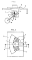
- a resistance-type liquid level measuring apparatus in the present invention is provided on an attachment plate 3 attached to an opening of a fuel tank 2, and is constructed, at a lower side of the attachment plate 3, as a resistance-type sensor 1 constituted by an insulating substrate 6 made of ceramic on which a conductor electrode 4 made of an alloy containing silver, for example, AgPd (silver palladium) alloy and a resistor 5 are formed by printing, and a slider 8 (movable contact) provided with a contact portion 7 which slides on the conductor electrode 4.
- a resistance-type sensor 1 constituted by an insulating substrate 6 made of ceramic on which a conductor electrode 4 made of an alloy containing silver, for example, AgPd (silver palladium) alloy and a resistor 5 are formed by printing, and a slider 8 (movable contact) provided with a contact portion 7 which slides on the conductor electrode 4.
- the conductor electrode 4 is made of plural lines of electrode patterns (a plurality of conductor electrodes 4) arranged in a fan shape (substantially parallel) along a rotation trajectory of the contact portion 7 and at suitable intervals on the insulating substrate 6, and the resistor 5 is made by firing a printed layer containing, for example, ruthenium oxide as its main ingredient, and is adhered so as to continuously cover a part of each of the plural lines of the electrode patterns constituting the conductor electrode 4.
- the vertical movement of a liquid level is transmitted to the slider 8 through a float 9 and an arm 10, the contact portion 7 slides on the conductor electrode 4 so that the conductor electrode 4 on the insulating substrate 6 comes in contact with the contact portion 7, a resistance value of an effective resistor between a position of the contacted conductor electrode 4 and one end side is changed, and a value of a current flowing between the contact portion 7 and the conductor electrode 4 is determined.
- the change of this current value is outputted as a detection signal of a voltage value through an output terminal.
- a power supply voltage V at this time is 10 v.
- a resistance value of the resistor 5 positioned between a conductor electrode PF corresponding to the F point equivalent to the full tank of the liquid level and a lower side conductor electrode P1 adjacent to this is set to be larger than a resistance value between other conductor electrodes P positioned at the lower side, the sum of voltage differences ⁇ VF respectively between detection voltages VF and V1 at the connection point when the movable contact 8 comes in contact with the conductor electrode PF and the conductor electrode P1 is 0.4 v (volt) or larger, and the indication characteristic at an indication unit 102 is made such that the F point is indicated until a voltage becomes one obtained by adding 0.4 v (volt) or larger to the detection voltage VO at the conductor electrode PF when sulfurization does not occur, whereby with respect to the indication at least at the F point position, even if the
- the error absorption structure at the F point in addition to the error absorption structure at the F point, if the foregoing structure is also used in which when the detected voltage VO equivalent to the full tank of the liquid level is made VF and the voltage equivalent to the low region is made VE, the voltage output of
- a resistance-type sensor 1 as a resistance-type liquid level measuring apparatus is contained in a fuel tank 2, and is provided on an attachment plate 3 attached to an opening of the fuel tank 2.
- a detecting unit is attached to the lower side of the attachment 3, which includes an insulating substrate 6 made of ceramic on which a conductor electrode 4 and a resistor 5 are formed by printing, and a slider 8 provided with a contact portion 7 which slides on the conductor electrode 4.
- the conductor electrode 4 is formed of plural lines of electrode patterns arranged in a fan shape along a rotation trajectory of the contact portion 7 and at suitable intervals on the insulating substrate 6.
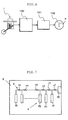
- the resistor 5 is formed by firing a printed layer containing, for example, ruthenium oxide as its main ingredient, and as shown in Fig. 2, it is adhered so as to continuously cover a part of each of the plural lines of the electrode patterns constituting the conductor electrode 4.
- the contact portion 7 is formed of a contact member 73 including a sliding portion 71 as a sliding contact portion to the conductor electrode 4 and a caulked portion 72 at a side opposite to the sliding portion 71, and is caulked and fixed to the slider 8 as a movable contact.
- the slider 8 is made of a metal plate having a spring property, for example, a metal plate made of phosphor bronze, and is supported and fixed so as to be moved according to a movable part formed of a float 9, which is vertically moved in accordance with a liquid surface of a fuel, and an arm 10, and is supported and fixed with respect to the insulating substrate 6 so that the contact portion 7 attached and fixed to that can be moved on the insulating substrate 6 according to the liquid surface.
- a metal plate having a spring property for example, a metal plate made of phosphor bronze
- Fig. 5 shows a circuit connection example in which the resistance-type sensor 1 forming the resistance-type liquid level measuring apparatus as stated above is used.
- the resistance-type sensor 1 as the resistance-type liquid level measuring apparatus attached to a predetermined position in a fuel tank for a vehicle includes the movable contact 8 (slider) which is coupled with the float arm floating on the liquid surface in the fuel tank and is rotated, and is constructed such that a number of conductor electrodes 4 are formed in parallel with each other on, for example, the ceramic insulating substrate 6, the resistor 5 formed by printing a resistive material so as to have the same resistance value between both ends is provided thereon, and the movable contact 8 slides on the conductor electrodes 4.
- the movable contact 8 is connected to the minus side of an on-vehicle power source BA, the resistor 5 is connected in series with a voltage dividing resistance 11 from the positive side of the power source BA, and a detection voltage VO at a connection point between the voltage dividing resistance 11 and the resistor 5 is made a detection output.
- a power supply voltage V at this time is 10 to 16 v (volt), here, 10 v, a resistance value RO of the voltage dividing resistance 11 is 300 ⁇ or larger, here, 420 ⁇ , a resistance value RE of the resistor 5 at the time equivalent to the low region of the liquid level, is 300 ⁇ or larger here, 447 ⁇ , and a resistance value RF at the time equivalent to a full tank is RE ⁇ 0.1, here, 13 ⁇ .
- of the output voltages of the E point and the F point becomes larger than 4 v (volt).
- the error of the voltage drop VS 0.4 v due to silver sulfide becomes 10 % or less with respect to a deflection angle between the E point and the F point, and as compared with the conventional indication including an error of 25% as in the prior art, a great improvement in precision is obtained, and the error can be suppressed within an almost permissible range in practical use.
- Reference numeral 100 designates a microcomputer as an operation unit; 101, a driving driver for making a predetermined voltage output in accordance with an instruction signal of the microcomputer 100; and 102, a display unit made of, for example, a cross coil-type instrument for angularly moving a pointer P in accordance with the driving voltage output from the driving driver 101.
- a detection signal of the resistance-type sensor 1 is converted into a driving signal corresponding to a liquid quantity through the microcomputer 100 and the driving driver 101, and the pointer P of the indication unit 102 is rotated by a predetermined angle on the basis of this driving signal to display the liquid quantity in the fuel tank 2.
- the microcomputer 100 is generally designed with voltage driving of, for example, 5 v through a constant voltage source from the power source BA, and it is desirable that as its input voltage, the detection voltage VO of the connection point between the voltage dividing resistance 11 and the resistor 5 is made to have a change width of 5 v or less.
- one end of the resistor 5 is connected to the voltage dividing resistance 11, and the other end is connected to the microcomputer 100, however, this is connected to a ground terminal common to the microcomputer 100, and actually, the other end may be put in an open state without being connected.
- the detection voltage VO corresponding to the liquid level detected by the resistance-type sensor 1 is converted by the microcomputer 100 in such a manner that when the voltage equivalent to the full tank of the liquid level is VF and the voltage equivalent to the low region is VE, the change width of the output voltages of the F point and the E point, VF and VE are correspondingly indicated with indication angles of the F point and the E point on the scale of the display unit 102, respectively. Since this output voltage width becomes 4 v or larger, with respect to the indication angles of the F point and the E point corresponding to the width of 4 v, the error voltage due to silver sulfide is 0. 4 v and the angle error is 10% or lower. Thus, a large influence disappears in practical use, and it becomes unnecessary to take troublesome and expensive measures, such as a change of electrode materials, for preventing the generation of silver sulfide itself.
- the resistance value RO of the voltage dividing resistance 11 is made 300 ⁇ or larger and the resistance value RE of the resistor 5 at the time equivalent to the low range is made 300 ⁇ or larger, since the increase of the current value under the power supply voltage of 10 v can be prevented as described above, and the detection voltage VO becomes 5 v or less and is suitable for detection by the microcomputer 100 at the subsequent stage. Even when the resistance values are set so that the detection voltage VO becomes 5 v or larger, if a voltage converting circuit such as a voltage dividing resistance intervenes between the resistor and the microcomputer 100, the influence of the voltage drop of 0.4 v due to silver sulfide can be suppressed to be less.
- the resistance values of the voltage dividing resistance and the resistor in the embodiment are set to be experimentally excellent in relation to the power supply voltage of a standard power source mounted in a vehicle, however, they may be set to values at which the voltage drop due to silver sulfide can be suppressed to 15% or less, preferably 10% or less with respect to the width between the detection voltages VF and VE according to the magnitude of the power supply voltage, and the magnitude is not particularly limited.
- the embodiment has the structure in which the arm is coupled with the float, even in a liquid level measuring apparatus of a structure in which a long insulating substrate is vertically suspended in a tank, and a ring float with a movable contact is made to float around that, a similar effect can be obtained by similarly setting resistance values.
- Fig. 7 shows another embodiment of the present invention, and the basic structure of a resistance-type sensor 1 is the same as the foregoing embodiment shown in Figs. 1 to 5.
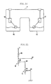
- conductor electrodes 4 and resistance values between them are equivalently shown, and among conductor electrodes P of the plurality of conductor electrodes 4 formed on an insulating substrate 6, the magnitude of a resistance value r1 of a resistor 5 positioned between a conductor electrode PF corresponding to the F point equivalent to the full tank and a lower side conductor electrode P1 adjacent to the former is set to be larger than resistance values r2 to re positioned between other lower side conductor electrodes P, and a voltage difference ⁇ VF between detection voltages VF and V1 of the connection point when the contact portion 7 of the slider 8 constituting the movable contact comes in contact with the conductor electrode PF and the conductor electrode P1 is made not less than 0.4 v (volt) equivalent to the voltage drop due to silver sulfide.
- the microcomputer 100 as the operation unit generates such indication characteristics that until the detection voltage VO reaches 0.6 v obtained by adding 0.4 v here to the detection voltage 0.2 v of the conductor electrode PF at the F point when sulfurization does not occur, the indication by the pointer P in the indication unit 102 is kept at a position equivalent to the F point on the scale, and the indication according to the detection voltage VO corresponding to the contact position of the contact portion 7 is made after the voltage exceeds 0.6 v.
- the detection voltage VO at the time of contact with the conductor electrode PF of the F point becomes 0.2 v, and since the actual resistance value change is large until the adjacent conductor electrode P1, the detection voltage VO is also largely changed between them as indicated by a broken line, however, since the portion corresponding to the F point on the scale of the indication unit 102 is indicated for the F point indication at the time of the full tank, there is no problem in practical use.
- the shape of a fuel tank is complicatedly changed, and in the liquid level detection by the resistance-type sensor 1, that is, in the system of measuring the height of the liquid surface, the fuel volume in the fuel tank is not faithfully indicated.
- the relation between the height of the liquid surface and the fuel volume corresponding to the height is checked in advance, the indication data corresponding to this relation is stored, and the indication with respect to the detection voltage VO is made, so that the indication more faithful to the fuel volume can also be made.
- the F point indication equivalent to 0.2 v is made by the microcomputer 100.
- the F point is indicated and the indication error to the lower side by the voltage drop of 0.4 v due to silver sulfide does not occur, so that a driver does not feel distrust.
- the F point is indicated so that the error of 0.4 v due to sulfurization does not occur on the indication.
- This added voltage may be set correspondingly to the voltage drop due to sulfurization, and the characteristic may be set by the microcomputer such that, for example, if the voltage drop due to sulfurization is about 0.6 v, until the voltage in which 0.6 v is added, for example, until the detection voltage VO becomes 0.8 v, the F point is indicated.
- the indication error at the F point due to sulfurization can be removed, and when the voltage difference ⁇ VF between the conductor electrode PF equivalent to the F point and the adjacent conductor electrode P1 is set to 0.4 v or larger, at least the voltage drop of 0.4 to 0.6 v due to sulfurization at the F point does not have an influence on the indication.
- the contact portion 7 is in contact with the conductor electrode PF equivalent to the full tank by refueling, even if the voltage drop 0.4 v due to sulfurization is generated, it is possible to prevent the indication error to the lower side from occurring.
- the F point is indicated until the voltage in which the predetermined voltage equivalent to the voltage drop due to sulfurization is added to the F point detection voltage VO at the normal time.
- the F point is indicated until the actual detection voltage VO of the adjacent conductor electrode P1 provided with the voltage difference ⁇ VF of 0.4 v or larger as the voltage drop or larger due to sulfurization, so that it is possible to facilitate the conversion data setting of the indication characteristic of the pointer P at the change point at the detection voltage VO of the adjacent conductor electrode P1, and as the need arises, such voltage may be adopted.
- the specific resistance values in the above embodiment are not limited to these, and although a calculation has been made under the power supply voltage V of 5 v, even in the case where it is 10 v, the object can be achieved by similar condition setting.
- the power supply voltage V of 10 v in the structure of the resistance-type sensor 1 explained in Fig.
- a saddle-type is adopted as a fuel tank, as in a motorcycle
- resistance-type sensors 1M and 1S are provided in a main tank TM and a sub-tank TS of a tank T, respectively, and a residual fuel of the whole tank T by the series connection of both the resistance-type sensors 1M and 1S is detected and displayed.
- a circuit as shown in Fig.
- the resistance value r1 between the conductor electrodes PF and P1 is set to be large, so that the voltage drop between them becomes 0.4 v or larger.
- the indication characteristic of the detection by the microcomputer 100 is set so that the F point is indicated until 0.4 v + 0.8 v.
- the resistance value r1 between the conductor electrodes PF and P1 of the respective resistance-type sensors 1M and 1S is increased to make each voltage drop between them 0.4 v, so that the judgment threshold of the voltage drop of 0.8 v due to sulfurization on the whole is provided.
- 0.8 v is set on the whole, and for example, the voltage drop between the conductor electrodes PF and P1 in the resistance-type sensor 1M is made 0.2 v, and setting is made so that the voltage drop between the conductor electrodes PF and P1 in the resistance-type sensor 1S becomes 0.6 v, and if the voltage drop of 0.8 v is obtained on the whole, the voltage drop of 0.8 v due to sulfurization may be similarly subjected to characteristic processing by the microcomputer 100.
- Fig. 12 shows an embodiment in which an indication unit 102 of the present invention is made an electronic indicator, for example, a liquid crystal indicator, and a liquid level is made a bar display of a plurality of segments.
- Fig. 12(A) shows an example of the bar display of the indication unit 102
- Fig. 12(B) is a view for explaining the way of producing the indication characteristic for driving the segments S of the bar display in the microcomputer 100.
- the indication unit 102 is constructed by a liquid crystal indicator, and the plurality of segments S are driven and controlled on a bar display unit 103, so that the liquid level is indicated by the lighting amount of the segments S.
- the number of the segments is made ten, and eight segments S1 to S8 are arranged side by side between an F point segment SF and an E point segment SE.
- the structure of the resistance-type sensor 1 is basically the same as that shown in Figs. 1 and 2, and the relation between the conductor electrode 4 and the resistor is equivalent to that shown in Fig. 7.
- the conductor electrode structure of this case if the number of the conductor electrodes is, for example, 50, it is appropriate that five conductor electrodes 4 are made to correspond to each segment S of the ten segments of the bar display unit 103, and a bar display is carried out at a uniform rate.
- mat electrodes the number of which corresponds to that of the respective segments S may be provided, or respective sets of five conductor electrodes 4 may be connected like a comb shape.
- the conductor electrodes 4 are allocated at a rate equal to the number of the segments, the F point segment SF lights up rather early though the tank is not actually filled up.
- the indication characteristic can be easily arbitrarily changed by changing the number of the conductor electrodes 4 corresponding to each of the segments S, or changing the resistance value of the resistor in each region.
- the resistance value r between the conductor electrodes 4 corresponding to a changeover point between the F point segment SF and the lower side segment S1 adjacent to this is set so that the detection voltage VO becomes 0.4 v or larger between the conductor electrodes.
- judgment control is made with a threshold corresponding to a contact position of the conductor electrode 4 corresponding to each segment S.
- Fig. 12B in which the X axis indicates conductor electrode lines including the five conductor electrodes PF to P4, and the Y axis indicates the ten segments SF, S1 to SE for display, and the lighting relation of the respective segments S at the time of contact with the respective conductor electrodes is shown.
- the resistance value of a resistor and the resistance value of a voltage dividing resistance are adjusted so that the detection voltage VO by the contact of the movable contact with the conductor electrode becomes 0.2 v at the time of contact with the conductor electrode PF equivalent to the F point, and the voltage drop between the electrodes becomes 0.1 v.
- the resistance value is set to be large so that a difference between the detection voltages VO of the conductor electrodes PF to P4 corresponding to the segment SF equivalent to the F point and the conductor electrode P5 corresponding to the adjacent segment S1 at the lower side is made 0.4 v or larger, here, 0.4 v.
- the detection voltage VO is changed from 0.2 v to 0.6 v until the conductor electrodes PF to P4, and when a shift to the conductor electrode P5 is made, the voltage becomes 1.0 v, and subsequently, it rises by a change of 0.1 v between the conductor electrodes.
- the microcomputer 100 converts indication characteristics with respect to such input characteristics.
- the conductor electrodes P corresponding to the respective segments S are connected to be united like a comb-like electrode, since the potential at the conductor electrodes is constant, for example, if the detection voltage difference between the F point and the E point is designed to be about 4 v under the power supply voltage of 5 v, voltage differences are generated at intervals of 0. 4 v in the conductor electrode group corresponding to the ten segments S.
- the microcomputer 100 outputs lighting signals of the segments S previously set correspondingly to the level of this detection voltage VO (the F point segment lights up until 0.6 v).
- the detection voltage at the conductor electrode group corresponding to the lower side segment S1 is made 0.6 v, and coincides with the detection voltage 0.6 v for switching on the F point segment SF.
- the resistance values are actually set so that the detection voltage difference between the conductor electrode group corresponding to the F point segment SF and the conductor electrode group corresponding to the lower segment S1 becomes 0.45 v, and a change of lighting to the lower segment S1 can be made certain.
- the detection voltage VO at the conductor electrodes PF to P4 corresponding to the F point segment SF is added with the voltage drop 0.4 v by this sulfurization, and is outputted as 0.6 v to 1.0 v.
- characteristics are set so that the segment SF lights up until the voltage reaches 1.0 v, and an indication error due to such sulfurization does not occur.
- the addition voltage is made 0.4 v in consideration of the voltage drop due to sulfurization, according to the degree of badness of fuel, a use material of a conductor electrode, an affinity with fuel, a use environment, and the like, a case has been confirmed in which an increase up to about 0.6 v occurs.
- a detection voltage difference between conductor electrodes at a changeover point is set to 0.6 v, and characteristic setting in the operation unit is also made to conform with this, so that similar indication can be carried out, and it would be realistic that with respect to such voltage setting, 0.4 v to 0.6 v is suitably selected and added according to the respective environments.
- the maximum deflection angle position higher than the F point scale is made an indication position equivalent to a full tank, and a detection voltage difference between the conductor electrode PF corresponding to this and the adjacent conductor electrode P1 may be made 0.4 v or larger, or a structure may be adopted such that a place higher than the F point on the dial is made a position equivalent to a full tank, and a detection voltage difference between the conductor electrode corresponding to the F point scale and the adjacent conductor electrode becomes 0.4 v or larger.
- a structure is adopted such that a difference of a detection voltage VO between an indication position equivalent to a full tank and a conductor electrode adjacent this and positioned at a changeover point for indicating a lower side indication position becomes a voltage drop due to silver sulfide or larger, so that an indication error to a lower side at the time of the full tank does not occur.
- the indication unit is a pointer-type instrument or an electronic indicator of a bar display or the like
- the accuracy at the F point is raised, and the total error can be made small so that a problem does not arise in practical use.
- the former system is best, and even if an error occurs at the lower side segment, it does not become a problem in practical use, and the F point segment can certainly light up at the time of the full tank even at the time of sulfurization.
- the deflection angle of the fuel gauge scale is as narrow as 90 degrees, and it is sufficient if a rough residual quantity state can be grasped.
- the accuracy adequate for practical use can be obtained, and even if sulfurization occurs, the indication of the full tank region higher than the F point scale can be made stable.
- the former system is adopted.
- the resistance-type liquid level measuring apparatus of the present invention is especially effective for a liquid level measuring apparatus in which an Ag (silver) component of an electrode or a contact is sulfurized by sulfur in fuel, and silver sulfide is deposited on the electrode or the contact surface.
- an Ag (silver) component of an electrode or a contact is sulfurized by sulfur in fuel, and silver sulfide is deposited on the electrode or the contact surface.
Landscapes
- Physics & Mathematics (AREA)
- General Physics & Mathematics (AREA)
- Fluid Mechanics (AREA)
- Level Indicators Using A Float (AREA)
- Cooling, Air Intake And Gas Exhaust, And Fuel Tank Arrangements In Propulsion Units (AREA)
- Measurement Of Levels Of Liquids Or Fluent Solid Materials (AREA)
Abstract
Description
Claims (13)
- A resistance-type liquid level measuring apparatus installed in a fuel tank, for detecting a fuel quantity in the tank, comprising a resistance-type sensor including a float floating according to a liquid level, an insulating substrate having a plurality of conductor electrodes connected with a resistor, and a movable contact interlocked with a movement of the float to come in contact with the conductor electrodes on the insulating substrate, wherein
a material containing silver is used as a material of the conductor electrodes or the movable contact, and
a voltage dividing resistance is connected with a power source in series with the resistor, and a voltage of a connection point between the voltage dividing resistance and the resistor is outputted as a signal corresponding to the liquid level, characterized in that
resistance values of the voltage dividing resistance and the resistor are set so that a voltage drop VS due to silver sulfide generated between the conductor electrode and the movable contact becomes 15% or less, preferably 10% or less with respect to a difference between a voltage VF equivalent to a full tank of the liquid level and a voltage VE equivalent to a low region. - A resistance-type liquid level measuring apparatus installed in a fuel tank, for detecting a fuel quantity in the tank, comprising a resistance-type sensor including a float floating according to a liquid level, an insulating substrate having a plurality of conductor electrodes connected with a resistor, and a movable contact interlocked with a movement of the float to come in contact with the conductor electrodes on the insulating substrate, wherein
a material containing silver is used as a material of the conductor electrodes or the movable contact, and
a voltage dividing resistance is connected with a power source in series with the resistor, and a voltage of a connection point between the voltage dividing resistance and the resistor is outputted as a signal corresponding to the liquid level, characterized in that
as a detection voltage VO outputted to the connection point, at a position of the movable contact, when a voltage equivalent to a full tank of the liquid level is VF, a voltage equivalent to a low region is VE, and a power supply voltage V is V = 10 to 16 v (volt), a resistance value RO of the voltage dividing resistance, a resistance value RE of the resistor equivalent to the low region of the liquid level, and a resistance value RF equivalent to a full tank are set so that |VF - VE| > 4 v (volt) is realized. - A resistance-type liquid level measuring apparatus installed in a fuel tank, for detecting a fuel quantity in the tank, comprising a resistance-type sensor including a float floating according to a liquid level, an insulating substrate having a plurality of conductor electrodes connected with a resistor, and a movable contact interlocked with a movement of the float to come in contact with the conductor electrodes on the insulating substrate, wherein
a material containing silver is used as a material of the conductor electrodes or the movable contact, and
a voltage dividing resistance is connected with a power source in series with the resistor, and a voltage of a connection point between the voltage dividing resistance and the resistor is outputted as a signal corresponding to the liquid level, characterized in that
as a detection voltage VO outputted to the connection point, at a position of the movable contact, when a voltage equivalent to a full tank of the liquid level is VF, a voltage equivalent to a low region is VE, and a power supply voltage is V, a resistance value RO >= 300 Ω of the voltage dividing resistance, a resistance value RE >= 300 Ω of the resistor equivalent to the low region of the liquid level, and a resistance value RF =< RE × 0.1 equivalent to a full tank are set so that |VF - VE| > 4 v (volt) is realized. - A resistance-type liquid level measuring apparatus according to any one of claims 1 to 3, characterized in that as the material of the movable contact, an alloy containing copper and nickel, or an alloy containing copper, nickel, and zinc is used.
- A resistance-type liquid level measuring apparatus according to any one of claims 1 to 3, characterized in that the power supply voltage V is made 10 to 16 v, the resistance value of the voltage dividing resistance RO is made 350 to 450 Ω, the resistance value RE of the resistor equivalent to the low region of the liquid level is made 400 to 500Ω, and the resistance value RF equivalent to the full tank is set within a range of 10 to 20 Ω.
- A resistance-type liquid level measuring apparatus according to any one of claims 1 to 3, characterized by comprising an operation unit to which the detection voltage VO of the connection point is inputted, and which detects the liquid level by a ratio with respect to the power supply voltage V, and an indication unit for indicating the detected liquid level by an output of this operation unit.
- A resistance-type liquid level measuring apparatus installed in a fuel tank, for detecting a fuel quantity in the tank, comprising a resistance-type sensor including a float floating according to a liquid level, an insulating substrate having a plurality of conductor electrodes connected with a resistor, and a movable contact interlocked with a movement of the float to come in contact with the conductor electrodes on the insulating substrate, wherein
a material containing silver is used as a material of the conductor electrodes or the movable contact, and
a voltage dividing resistance is connected with a power source in series with the resistor, and a voltage of a connection point between the voltage dividing resistance and the resistor is outputted as a signal corresponding to the liquid level, characterized in that
a resistance value of the resistor positioned between a conductor electrode PF among the conductor electrodes. with which the movable contact comes in contact at a full tank of the liquid level, and a lower side conductor electrode P1 adjacent to this is set to be larger than a resistance value between the other conductor electrodes P positioned at the lower side, and a voltage difference ΔVF between detection voltages VF and V1 at the connection point when the movable contact comes in contact with the conductor electrode PF and the conductor electrode P1 becomes 0.4 v (volt) or larger. - A resistance-type liquid level measuring apparatus installed in a fuel tank, for detecting a fuel quantity in the tank, comprising resistance-type sensors each including a float floating according to a liquid level, an insulating substrate having a plurality of conductor electrodes connected with a resistor, and a movable contact interlocked with a movement of the float to come in contact with the conductor electrodes on the insulating substrate, wherein
the resistance-type sensors are installed in a main tank and a sub-tank of the fuel tank, and an output end of the movable contact of one of them is connected to the conductor electrode of the other so that the resistors of the respective resistance-type sensors are connected in series with a power source,
a material containing silver is used as a material of the conductor electrodes or the movable contact, and
a voltage dividing resistance is connected with the power source in series with the resistor of the one, and a voltage of a connection point between the voltage dividing resistance and the resistor is outputted as a signal corresponding to the liquid level, characterized in that
a resistance value of the resistor positioned between a conductor electrode PF among the conductor electrodes, with which the movable contact comes in contact at a full tank of the liquid level, and a lower side conductor electrode P1 adjacent to this is set to be larger than a resistance value between the other conductor electrodes P positioned at the lower side, and the sum of voltage differences ΔVF respectively between detection voltages VF and V1 at the connection point when the movable contact comes in contact with the conductor electrode PF and the conductor electrode P1 becomes 0.8 v (volt) or larger. - A resistance-type liquid level measuring apparatus according to claim 7 or 8, characterized by comprising an operation unit to which a detection voltage VO of the connection point is inputted, and which detects the liquid level by a ratio with respect to a power supply voltage V, and an indication unit for indicating the detected liquid level by an output of the operation unit, wherein the operation unit generates such an indication characteristic that F point indication equivalent to a full tank in the indication unit is carried out until the detection voltage VO becomes a voltage obtained by adding 0.4 v (volt) or larger, or 0.8 v (volt) or larger to the detection voltage VF at the conductor electrode PF at a normal time when sulfurization does not occur.
- A resistance-type liquid level measuring apparatus according to claim 7 or 8, characterized by comprising an operation unit to which a detection voltage VO of the connection point is inputted, and which detects the liquid level by a ratio with respect to a power supply voltage V, and an indication unit for indicating the detected liquid level by an output of the operation unit, wherein the operation unit generates such an indication characteristic that F point indication equivalent to a full tank in the indication unit is carried out until the detection voltage V1 of the resistance-type sensor at the connection point when the movable contact comes in contact with the conductor electrode P1 adjacent to the conductor electrode PF or a voltage of the sum of the detection voltages V1.
- A resistance-type liquid level measuring apparatus according to any one of claims 7 to 10, characterized in that resistance values of the voltage dividing resistance and the resistor are set so that a voltage drop VS due to silver sulfide generated between the conductor electrode and the movable contact becomes 15% or less, preferably 10% or less with respect to a difference between a voltage VF equivalent to a full tank of the liquid level and a voltage VE equivalent to a low region.
- A resistance-type liquid level measuring apparatus installed in a fuel tank, for detecting a fuel quantity in the tank, comprising a resistance-type sensor including a float floating according to a liquid level, an insulating substrate having a plurality of conductor electrodes connected with a resistor, and a movable contact interlocked with a movement of the float to come in contact with the conductor electrodes on the insulating substrate, wherein
a material containing silver is used as a material of the conductor electrodes or the movable contact,
a voltage dividing resistance is connected with a power source in series with the resistor, and a voltage of a connection point between the voltage dividing resistance and the resistor is outputted as a signal corresponding to the liquid level, and
the apparatus further comprises an operation unit to which a detection voltage VO of the connection point is inputted, and which detects the liquid level by the detection voltage VO, and an indication unit for indicating the detected liquid level by an output of this operation unit,
characterized in that the indication unit is constituted by a bar display made of a plurality of segments according to an electronic indicator and, a difference of the detection voltage VO between the conductor electrodes of the resistance-type sensor positioned at an indication segment equivalent to a full tank and a changeover point for driving a lower side segment adjacent to this is set to 0.4 v (volt) or larger. - A resistance-type liquid level measuring apparatus installed in a fuel tank, for detecting a fuel quantity in the tank, comprising a resistance-type sensor including a float floating according to a liquid level, an insulating substrate having a plurality of conductor electrodes connected with a resistor, and a movable contact interlocked with a movement of the float to come in contact with the conductor electrodes on the insulating substrate, wherein
a material containing silver is used as a material of the conductor electrodes or the movable contact,
a voltage dividing resistance is connected with a power source in series with the resistor, and a voltage of a connection point between the voltage dividing resistance and the resistor is outputted as a signal corresponding to the liquid level, and
the apparatus further comprises an operation unit to which a detection voltage VO of the connection point is inputted, and which detects the liquid level by the detection voltage VO, and an indication unit for indicating the detected liquid level by an output of this operation unit,
characterized in that the indication unit makes setting such that a difference of the detection voltage VO between the conductor electrodes of the resistance-type sensor positioned at an indication position equivalent to a full tank and a changeover point for driving a lower side position adjacent to this becomes equal to or larger than a voltage drop due to silver sulfide when the silver sulfide is generated.
Applications Claiming Priority (5)
| Application Number | Priority Date | Filing Date | Title |
|---|---|---|---|
| JP2000235267 | 2000-07-31 | ||
| JP2000235267 | 2000-07-31 | ||
| JP2001188296A JP3555136B2 (en) | 2000-07-31 | 2001-06-21 | Resistance type liquid level measuring device |
| JP2001188296 | 2001-06-21 | ||
| PCT/JP2001/006255 WO2002014806A1 (en) | 2000-07-31 | 2001-07-18 | Resistance type liquid level measuring apparatus |
Publications (3)
| Publication Number | Publication Date |
|---|---|
| EP1291623A1 true EP1291623A1 (en) | 2003-03-12 |
| EP1291623A4 EP1291623A4 (en) | 2005-07-06 |
| EP1291623B1 EP1291623B1 (en) | 2011-05-25 |
Family
ID=26597270
Family Applications (1)
| Application Number | Title | Priority Date | Filing Date |
|---|---|---|---|
| EP01950029A Expired - Lifetime EP1291623B1 (en) | 2000-07-31 | 2001-07-18 | Resistance type liquid level measuring apparatus |
Country Status (6)
| Country | Link |
|---|---|
| US (1) | US6724201B2 (en) |
| EP (1) | EP1291623B1 (en) |
| JP (1) | JP3555136B2 (en) |
| KR (2) | KR100833043B1 (en) |
| CN (1) | CN100430699C (en) |
| WO (1) | WO2002014806A1 (en) |
Cited By (2)
| Publication number | Priority date | Publication date | Assignee | Title |
|---|---|---|---|---|
| US9435680B2 (en) | 2014-03-24 | 2016-09-06 | Deringer-Ney, Inc. | Apparatuses and methods for fuel level sensing |
| US9488515B2 (en) | 2014-03-24 | 2016-11-08 | Deringer-Ney, Inc. | Apparatuses and methods for fuel level sensing |
Families Citing this family (43)
| Publication number | Priority date | Publication date | Assignee | Title |
|---|---|---|---|---|
| JP3901968B2 (en) * | 2001-08-27 | 2007-04-04 | 矢崎総業株式会社 | Liquid level detector |
| KR20040045068A (en) * | 2002-11-22 | 2004-06-01 | 현대자동차주식회사 | Fuel sender appraising method |
| JP2004184097A (en) * | 2002-11-29 | 2004-07-02 | Nippon Seiki Co Ltd | Liquid level detector |
| US7293578B2 (en) | 2004-01-22 | 2007-11-13 | Rochester Gauges, Inc. | Gauge assembly having a stop fill device |
| US7921873B2 (en) | 2004-01-22 | 2011-04-12 | Rochester Gauges, Inc. | Service valve assembly having a stop-fill device and a liquid level indicating dial |
| US7726334B2 (en) | 2004-01-22 | 2010-06-01 | Rochester Gauges, Inc. | Service valve assembly having a stop-fill device and remote liquid level indicator |
| JP4619685B2 (en) * | 2004-05-07 | 2011-01-26 | 矢崎総業株式会社 | Liquid level sensor using float and liquid level detection method using float |
| US6956384B1 (en) * | 2004-11-05 | 2005-10-18 | Seoul National University Industry Foundation | Linear displacement transducer with improved accuracy |
| FI118059B (en) * | 2005-01-28 | 2007-06-15 | Valtion Teknillinen | Position Sensor and Method for Diagnosing Position Sensor |
| JP2006284198A (en) * | 2005-03-31 | 2006-10-19 | Agilent Technol Inc | Resistor and current measuring apparatus and method using the same |
| USD539685S1 (en) * | 2005-06-07 | 2007-04-03 | Rochester Gauges, Inc. | Dial assembly design |
| USD538693S1 (en) * | 2005-06-07 | 2007-03-20 | Rochester Gauges, Inc. | Gauge dial housing |
| US20070030111A1 (en) * | 2005-08-02 | 2007-02-08 | Beck David B | Humidity sensor |
| US7573365B2 (en) * | 2005-12-12 | 2009-08-11 | Sensitron, Inc. | Humidity sensor |
| USD583693S1 (en) | 2006-03-30 | 2008-12-30 | Rochester Gauges, Inc. | Dial assembly for a gauge |
| US20100229964A1 (en) * | 2006-08-18 | 2010-09-16 | Rochester Gauges, Inc. | Service valve assembly having a stop-fill device and remote liquid level indicator |
| JP5213343B2 (en) * | 2007-03-22 | 2013-06-19 | 矢崎総業株式会社 | Resistive plate and liquid level detecting device provided with the resistive plate |
| JP4959419B2 (en) * | 2007-05-23 | 2012-06-20 | 矢崎総業株式会社 | Liquid level detector |
| JP4689642B2 (en) * | 2007-05-30 | 2011-05-25 | 愛三工業株式会社 | Fuel supply device |
| JP4961272B2 (en) * | 2007-06-13 | 2012-06-27 | 矢崎総業株式会社 | Liquid level detector |
| DE102007038428A1 (en) * | 2007-08-14 | 2009-02-19 | Robert Bosch Gmbh | Tank level indicator |
| US7690323B2 (en) * | 2007-10-31 | 2010-04-06 | Rochester Gauges, Inc. | Gauge head assembly with non-magnetic insert |
| CN101470001B (en) * | 2007-12-27 | 2011-12-14 | 英业达股份有限公司 | Method for Automatically Planning Refueling Route |
| JP5483277B2 (en) * | 2009-11-09 | 2014-05-07 | 矢崎総業株式会社 | Contact of liquid level detection device and liquid level detection device |
| CN102305656B (en) * | 2011-07-29 | 2013-02-06 | 联合汽车电子有限公司 | Liquid level indicating system and contact resistance washing circuit |
| DE102011088816A1 (en) * | 2011-12-16 | 2013-06-20 | Continental Automotive Gmbh | Level sensor in a fuel tank of a motor vehicle, manufacturing method for such a level sensor and method for operating such a level sensor |
| US9605952B2 (en) | 2012-03-08 | 2017-03-28 | Quality Manufacturing Inc. | Touch sensitive robotic gripper |
| CA2863197A1 (en) | 2012-03-08 | 2013-09-12 | Quality Manufacturing Inc. | Touch sensitive robotic gripper |
| CN103017856B (en) * | 2012-12-18 | 2014-09-24 | 山东大学 | Automobile fuel tank oil level abnormal detection and reporting device |
| US10634579B1 (en) * | 2013-07-12 | 2020-04-28 | Hill-Rom Services, Inc. | Methods and apparatus for detecting position of a liquid |
| JP6187752B2 (en) * | 2013-07-12 | 2017-08-30 | マツダ株式会社 | Fuel display control device |
| US11313757B2 (en) | 2013-07-12 | 2022-04-26 | Hill-Rom Services, Inc. | Methods and apparatus for detecting a position of liquid |
| JP5860441B2 (en) * | 2013-08-09 | 2016-02-16 | 富士重工業株式会社 | Engine oil level indicator |
| GB2523816B (en) * | 2014-03-07 | 2018-11-21 | Jaguar Land Rover Ltd | Fuel level sensor apparatus and support structure therefor |
| KR101755775B1 (en) | 2014-12-09 | 2017-07-07 | 현대자동차주식회사 | Apparatus and Method for detecting filter contamination of fuel cell |
| US10718359B2 (en) | 2015-08-21 | 2020-07-21 | Quality Manufacturing Inc. | Devices and systems for producing rotational actuation |
| JP6561792B2 (en) * | 2015-11-20 | 2019-08-21 | 日本精機株式会社 | Residual fuel detector |
| CN106248178A (en) * | 2016-08-30 | 2016-12-21 | 重庆万力联兴实业(集团)有限公司 | Automobile fuel pump oil level electric resistance sensor detection device |
| JP7043178B2 (en) * | 2017-03-23 | 2022-03-29 | 太陽誘電株式会社 | Simulation method of equivalent circuit of passive element and its device |
| US11131573B2 (en) * | 2017-12-01 | 2021-09-28 | GM Global Technology Operations LLC | Offset detection for fuel level sensor fault |
| CN112444308A (en) * | 2019-08-30 | 2021-03-05 | 厦门雅迅网络股份有限公司 | Vehicle-mounted oil quantity monitoring fault judgment method |
| CN113712282A (en) * | 2021-08-03 | 2021-11-30 | 深圳市基克纳科技有限公司 | Dry burning prevention control method and device, electronic atomization device and readable storage medium |
| CN116659616A (en) * | 2023-05-12 | 2023-08-29 | 箭牌家居集团股份有限公司 | Liquid level sensor, liquid level detection circuit, control system and intelligent bathtub |
Family Cites Families (10)
| Publication number | Priority date | Publication date | Assignee | Title |
|---|---|---|---|---|
| NL8301598A (en) | 1983-05-06 | 1984-12-03 | Eduard Thomas Jacobus Van Der | HEAT GENERATOR. |
| SE452800B (en) * | 1984-01-23 | 1987-12-14 | Volvo Ab | FUEL METERS FOR VEHICLES |
| JP2516283B2 (en) | 1991-03-27 | 1996-07-24 | 株式会社トクヤマ | Method for producing polypropylene resin molded product |
| JP2593049Y2 (en) * | 1992-07-31 | 1999-03-31 | 株式会社カンセイ | Liquid level detector |
| CN2142564Y (en) * | 1992-12-07 | 1993-09-22 | 顾长安 | Reed contact type liquid level signal sensor |
| JP3660051B2 (en) * | 1996-04-19 | 2005-06-15 | 矢崎総業株式会社 | Fuel tank fuel level measuring device |
| EP0806637A3 (en) * | 1996-05-09 | 1998-01-07 | CTS Corporation | Fuel level indicator systems |
| KR19980058940A (en) * | 1996-12-30 | 1998-10-07 | 조희재 | Fuel detection device of car fuel tank |
| JPH11337387A (en) | 1998-05-29 | 1999-12-10 | Nippon Seiki Kk | Liquid level detector |
| JP2000136956A (en) * | 1998-10-30 | 2000-05-16 | Nippon Seiki Co Ltd | Liquid level-detecting apparatus and manufacture for conductor electrode used therein |
-
2001
- 2001-06-21 JP JP2001188296A patent/JP3555136B2/en not_active Expired - Lifetime
- 2001-07-18 US US10/089,144 patent/US6724201B2/en not_active Expired - Lifetime
- 2001-07-18 WO PCT/JP2001/006255 patent/WO2002014806A1/en not_active Ceased
- 2001-07-18 EP EP01950029A patent/EP1291623B1/en not_active Expired - Lifetime
- 2001-07-18 CN CNB018022367A patent/CN100430699C/en not_active Expired - Lifetime
- 2001-07-18 KR KR1020077011834A patent/KR100833043B1/en not_active Expired - Fee Related
- 2001-07-18 KR KR1020027004101A patent/KR100812949B1/en not_active Expired - Fee Related
Cited By (2)
| Publication number | Priority date | Publication date | Assignee | Title |
|---|---|---|---|---|
| US9435680B2 (en) | 2014-03-24 | 2016-09-06 | Deringer-Ney, Inc. | Apparatuses and methods for fuel level sensing |
| US9488515B2 (en) | 2014-03-24 | 2016-11-08 | Deringer-Ney, Inc. | Apparatuses and methods for fuel level sensing |
Also Published As
| Publication number | Publication date |
|---|---|
| KR20070072926A (en) | 2007-07-06 |
| KR100833043B1 (en) | 2008-05-27 |
| US20020149380A1 (en) | 2002-10-17 |
| KR20020042849A (en) | 2002-06-07 |
| EP1291623A4 (en) | 2005-07-06 |
| JP3555136B2 (en) | 2004-08-18 |
| US6724201B2 (en) | 2004-04-20 |
| CN100430699C (en) | 2008-11-05 |
| KR100812949B1 (en) | 2008-03-11 |
| CN1386191A (en) | 2002-12-18 |
| EP1291623B1 (en) | 2011-05-25 |
| JP2002116078A (en) | 2002-04-19 |
| WO2002014806A1 (en) | 2002-02-21 |
Similar Documents
| Publication | Publication Date | Title |
|---|---|---|
| US6724201B2 (en) | Resistance type liquid level measuring apparatus | |
| US6868724B2 (en) | Sealed fuel level sensor | |
| US5146785A (en) | Fluid level sensor with stair step output | |
| KR20010033652A (en) | Level indicator and method of manufacturing conductor electrode of level indicator | |
| US4789946A (en) | System for measuring the level of filling | |
| AU624642B2 (en) | Liquid level sender with linear float | |
| US3678749A (en) | Floatless fluid level gauge | |
| JP2012168151A (en) | Liquid level detector | |
| US7541911B2 (en) | Resistance plate and liquid level detection apparatus provided with said resistance plate | |
| JP5711599B2 (en) | Liquid level detector | |
| US7038473B2 (en) | Method and apparatus for measuring a fluid level and a motor vehicle provided with such apparatus | |
| WO1993025869A1 (en) | Vertical sweep liquid level sensor | |
| JPH0476567B2 (en) | ||
| JPS5836029Y2 (en) | Remaining amount enlarged display type liquid level meter | |
| WO2003003384A2 (en) | Fuel level sensing system | |
| JP2001304942A (en) | Fuel meter for vehicle | |
| KR100912777B1 (en) | Car Fuel Gauge | |
| JP5961356B2 (en) | Liquid level detection device and manufacturing method thereof | |
| JP2003042829A (en) | Sliding resistance type liquid level detection apparatus | |
| CN211504335U (en) | High-resolution oil level sensor | |
| KR100995742B1 (en) | Method for manufacturing conductor electrodes of fuel gauge for vehicle by double chain | |
| JP2004028893A (en) | Resistance type liquid level-measuring instrument | |
| CN1854693A (en) | Oil-level sensor and its circuits | |
| US20080053219A1 (en) | Multifunction fuel sensor | |
| JP2002168676A (en) | Fuel detector for vehicle |
Legal Events
| Date | Code | Title | Description |
|---|---|---|---|
| PUAI | Public reference made under article 153(3) epc to a published international application that has entered the european phase |
Free format text: ORIGINAL CODE: 0009012 |
|
| 17P | Request for examination filed |
Effective date: 20020405 |
|
| AK | Designated contracting states |
Kind code of ref document: A1 Designated state(s): AT BE CH CY DE DK ES FI FR GB GR IE IT LI LU MC NL PT SE TR |
|
| RBV | Designated contracting states (corrected) |
Designated state(s): DE FR GB IT |
|
| A4 | Supplementary search report drawn up and despatched |
Effective date: 20050523 |
|
| 17Q | First examination report despatched |
Effective date: 20070827 |
|
| GRAP | Despatch of communication of intention to grant a patent |
Free format text: ORIGINAL CODE: EPIDOSNIGR1 |
|
| RIN1 | Information on inventor provided before grant (corrected) |
Inventor name: ENOMOTO, KIYOSHI,C/O NIPPON SEIKI CO., LTD. Inventor name: SATO, KOICHI,C/O NIPPON SEIKI CO., LTD. |
|
| GRAS | Grant fee paid |
Free format text: ORIGINAL CODE: EPIDOSNIGR3 |
|
| GRAA | (expected) grant |
Free format text: ORIGINAL CODE: 0009210 |
|
| AK | Designated contracting states |
Kind code of ref document: B1 Designated state(s): DE FR GB IT |
|
| REG | Reference to a national code |
Ref country code: GB Ref legal event code: FG4D |
|
| REG | Reference to a national code |
Ref country code: DE Ref legal event code: R096 Ref document number: 60144696 Country of ref document: DE Effective date: 20110707 |
|
| PLBE | No opposition filed within time limit |
Free format text: ORIGINAL CODE: 0009261 |
|
| STAA | Information on the status of an ep patent application or granted ep patent |
Free format text: STATUS: NO OPPOSITION FILED WITHIN TIME LIMIT |
|
| 26N | No opposition filed |
Effective date: 20120228 |
|
| REG | Reference to a national code |
Ref country code: DE Ref legal event code: R097 Ref document number: 60144696 Country of ref document: DE Effective date: 20120228 |
|
| REG | Reference to a national code |
Ref country code: FR Ref legal event code: PLFP Year of fee payment: 16 |
|
| REG | Reference to a national code |
Ref country code: FR Ref legal event code: PLFP Year of fee payment: 17 |
|
| REG | Reference to a national code |
Ref country code: FR Ref legal event code: PLFP Year of fee payment: 18 |
|
| PGFP | Annual fee paid to national office [announced via postgrant information from national office to epo] |
Ref country code: FR Payment date: 20200611 Year of fee payment: 20 |
|
| PGFP | Annual fee paid to national office [announced via postgrant information from national office to epo] |
Ref country code: GB Payment date: 20200708 Year of fee payment: 20 Ref country code: DE Payment date: 20200707 Year of fee payment: 20 |
|
| PGFP | Annual fee paid to national office [announced via postgrant information from national office to epo] |
Ref country code: IT Payment date: 20200610 Year of fee payment: 20 |
|
| REG | Reference to a national code |
Ref country code: DE Ref legal event code: R071 Ref document number: 60144696 Country of ref document: DE |
|
| REG | Reference to a national code |
Ref country code: GB Ref legal event code: PE20 Expiry date: 20210717 |
|
| PG25 | Lapsed in a contracting state [announced via postgrant information from national office to epo] |
Ref country code: GB Free format text: LAPSE BECAUSE OF EXPIRATION OF PROTECTION Effective date: 20210717 |