EP1291515A2 - Temperature estimating apparatus for internal combustion engine - Google Patents
Temperature estimating apparatus for internal combustion engine Download PDFInfo
- Publication number
- EP1291515A2 EP1291515A2 EP02020009A EP02020009A EP1291515A2 EP 1291515 A2 EP1291515 A2 EP 1291515A2 EP 02020009 A EP02020009 A EP 02020009A EP 02020009 A EP02020009 A EP 02020009A EP 1291515 A2 EP1291515 A2 EP 1291515A2
- Authority
- EP
- European Patent Office
- Prior art keywords
- temperature
- exhaust
- adsorbent
- internal combustion
- combustion engine
- Prior art date
- Legal status (The legal status is an assumption and is not a legal conclusion. Google has not performed a legal analysis and makes no representation as to the accuracy of the status listed.)
- Granted
Links
Images


Classifications
-
- G—PHYSICS
- G01—MEASURING; TESTING
- G01K—MEASURING TEMPERATURE; MEASURING QUANTITY OF HEAT; THERMALLY-SENSITIVE ELEMENTS NOT OTHERWISE PROVIDED FOR
- G01K7/00—Measuring temperature based on the use of electric or magnetic elements directly sensitive to heat ; Power supply therefor, e.g. using thermoelectric elements
- G01K7/42—Circuits effecting compensation of thermal inertia; Circuits for predicting the stationary value of a temperature
-
- F—MECHANICAL ENGINEERING; LIGHTING; HEATING; WEAPONS; BLASTING
- F02—COMBUSTION ENGINES; HOT-GAS OR COMBUSTION-PRODUCT ENGINE PLANTS
- F02D—CONTROLLING COMBUSTION ENGINES
- F02D41/00—Electrical control of supply of combustible mixture or its constituents
- F02D41/02—Circuit arrangements for generating control signals
- F02D41/021—Introducing corrections for particular conditions exterior to the engine
- F02D41/0235—Introducing corrections for particular conditions exterior to the engine in relation with the state of the exhaust gas treating apparatus
- F02D41/024—Introducing corrections for particular conditions exterior to the engine in relation with the state of the exhaust gas treating apparatus to increase temperature of the exhaust gas treating apparatus
-
- F—MECHANICAL ENGINEERING; LIGHTING; HEATING; WEAPONS; BLASTING
- F02—COMBUSTION ENGINES; HOT-GAS OR COMBUSTION-PRODUCT ENGINE PLANTS
- F02D—CONTROLLING COMBUSTION ENGINES
- F02D41/00—Electrical control of supply of combustible mixture or its constituents
- F02D41/02—Circuit arrangements for generating control signals
- F02D41/04—Introducing corrections for particular operating conditions
- F02D41/047—Taking into account fuel evaporation or wall wetting
-
- F—MECHANICAL ENGINEERING; LIGHTING; HEATING; WEAPONS; BLASTING
- F02—COMBUSTION ENGINES; HOT-GAS OR COMBUSTION-PRODUCT ENGINE PLANTS
- F02D—CONTROLLING COMBUSTION ENGINES
- F02D41/00—Electrical control of supply of combustible mixture or its constituents
- F02D41/0025—Controlling engines characterised by use of non-liquid fuels, pluralities of fuels, or non-fuel substances added to the combustible mixtures
- F02D41/0047—Controlling exhaust gas recirculation [EGR]
- F02D41/0065—Specific aspects of external EGR control
- F02D2041/0067—Determining the EGR temperature
-
- F—MECHANICAL ENGINEERING; LIGHTING; HEATING; WEAPONS; BLASTING
- F02—COMBUSTION ENGINES; HOT-GAS OR COMBUSTION-PRODUCT ENGINE PLANTS
- F02D—CONTROLLING COMBUSTION ENGINES
- F02D2200/00—Input parameters for engine control
- F02D2200/02—Input parameters for engine control the parameters being related to the engine
- F02D2200/04—Engine intake system parameters
- F02D2200/0406—Intake manifold pressure
-
- F—MECHANICAL ENGINEERING; LIGHTING; HEATING; WEAPONS; BLASTING
- F02—COMBUSTION ENGINES; HOT-GAS OR COMBUSTION-PRODUCT ENGINE PLANTS
- F02D—CONTROLLING COMBUSTION ENGINES
- F02D2200/00—Input parameters for engine control
- F02D2200/02—Input parameters for engine control the parameters being related to the engine
- F02D2200/04—Engine intake system parameters
- F02D2200/0414—Air temperature
-
- F—MECHANICAL ENGINEERING; LIGHTING; HEATING; WEAPONS; BLASTING
- F02—COMBUSTION ENGINES; HOT-GAS OR COMBUSTION-PRODUCT ENGINE PLANTS
- F02D—CONTROLLING COMBUSTION ENGINES
- F02D2200/00—Input parameters for engine control
- F02D2200/02—Input parameters for engine control the parameters being related to the engine
- F02D2200/04—Engine intake system parameters
- F02D2200/0418—Air humidity
-
- F—MECHANICAL ENGINEERING; LIGHTING; HEATING; WEAPONS; BLASTING
- F02—COMBUSTION ENGINES; HOT-GAS OR COMBUSTION-PRODUCT ENGINE PLANTS
- F02D—CONTROLLING COMBUSTION ENGINES
- F02D2200/00—Input parameters for engine control
- F02D2200/02—Input parameters for engine control the parameters being related to the engine
- F02D2200/08—Exhaust gas treatment apparatus parameters
- F02D2200/0802—Temperature of the exhaust gas treatment apparatus
- F02D2200/0804—Estimation of the temperature of the exhaust gas treatment apparatus
-
- F—MECHANICAL ENGINEERING; LIGHTING; HEATING; WEAPONS; BLASTING
- F02—COMBUSTION ENGINES; HOT-GAS OR COMBUSTION-PRODUCT ENGINE PLANTS
- F02D—CONTROLLING COMBUSTION ENGINES
- F02D41/00—Electrical control of supply of combustible mixture or its constituents
- F02D41/02—Circuit arrangements for generating control signals
- F02D41/14—Introducing closed-loop corrections
- F02D41/1438—Introducing closed-loop corrections using means for determining characteristics of the combustion gases; Sensors therefor
- F02D41/1444—Introducing closed-loop corrections using means for determining characteristics of the combustion gases; Sensors therefor characterised by the characteristics of the combustion gases
- F02D41/1446—Introducing closed-loop corrections using means for determining characteristics of the combustion gases; Sensors therefor characterised by the characteristics of the combustion gases the characteristics being exhaust temperatures
-
- G—PHYSICS
- G01—MEASURING; TESTING
- G01K—MEASURING TEMPERATURE; MEASURING QUANTITY OF HEAT; THERMALLY-SENSITIVE ELEMENTS NOT OTHERWISE PROVIDED FOR
- G01K2205/00—Application of thermometers in motors, e.g. of a vehicle
- G01K2205/04—Application of thermometers in motors, e.g. of a vehicle for measuring exhaust gas temperature
-
- Y—GENERAL TAGGING OF NEW TECHNOLOGICAL DEVELOPMENTS; GENERAL TAGGING OF CROSS-SECTIONAL TECHNOLOGIES SPANNING OVER SEVERAL SECTIONS OF THE IPC; TECHNICAL SUBJECTS COVERED BY FORMER USPC CROSS-REFERENCE ART COLLECTIONS [XRACs] AND DIGESTS
- Y02—TECHNOLOGIES OR APPLICATIONS FOR MITIGATION OR ADAPTATION AGAINST CLIMATE CHANGE
- Y02T—CLIMATE CHANGE MITIGATION TECHNOLOGIES RELATED TO TRANSPORTATION
- Y02T10/00—Road transport of goods or passengers
- Y02T10/10—Internal combustion engine [ICE] based vehicles
- Y02T10/12—Improving ICE efficiencies
Definitions
- the present invention relates to a temperature estimating apparatus for an internal combustion engine which estimates the temperature of an exhaust device such as a catalyzer arranged in an exhaust system through calculations.
- one type of known temperature estimating apparatus thermodynamically calculates the temperature of an exhaust device in an exhaust system of an internal combustion engine. More specifically, the exhaust device is thermodynamically modeled to estimate a heat exchanging state between the exhaust device and exhaust gases to calculate the temperature of the exhaust device.
- the temperature of the exhaust device is estimated in this manner because a detecting device such as a temperature sensor is relatively expensive to cause an increase in the manufacturing cost, in addition to its low responsibility.
- the temperature estimating apparatus avoids such problems to increase the responsibility in detecting the temperature and reduce the manufacturing cost.
- the conventional temperature estimating apparatus could fail to correctly calculate the temperature of the exhaust device when the internal combustion engine is started under a low temperature condition for reasons set forth below.
- the saturated steam pressure of exhaust gases becomes lower associated with a reduction in the temperature of the exhaust gases passing through the exhaust device, thereby possibly resulting in condensation of moisture contained in the exhaust gases on wall surfaces of the exhaust device.
- heat applied from the exhaust gases to condensed water is consumed for a phase change from the condensed water to stream as latent heat of vaporization, so that the exhaust device does not change in temperature. It is therefore necessary to calculate the temperature of the exhaust device in consideration of the influence of the condensed water thus produced.
- the present invention has been made to solve the problem as mentioned above, and it is an object of the invention to provide a temperature estimating apparatus for an internal combustion engine which is capable of correctly calculating the temperature of an exhaust device even when the internal combustion engine is started under low temperature conditions.
- the present invention provides a temperature estimating apparatus for an internal combustion engine arranged in an exhaust system of the internal combustion engine for estimating a temperature of an exhaust device for purifying exhaust gases through calculations.
- the temperature estimating apparatus is characterized by comprising operating condition detecting means for detecting an operating condition of the internal combustion engine, including a state of intake air; humidity detecting means for detecting a humidity of exhaust gases; and device temperature calculating means for calculating the temperature of the exhaust device in accordance with the detected operating condition of the internal combustion engine and the detected humidity of the exhaust gases.
- the temperature estimating apparatus for an internal combustion engine of the present invention calculates the temperature of the exhaust device in accordance with a detected operating condition of the internal combustion engine, including the state of intake air, and the humidity of exhaust gases in the exhaust system. Therefore, even when the condensation is highly likely to occur due to a low external temperature, the temperature of the exhaust gas is calculated only when exhaust gases have a low humidity and are free from condensation, thereby making it possible to calculate the temperature of the exhaust device while avoiding the influence of the condensation. As a result, the temperature estimating apparatus for an internal combustion engine of the present invention can correctly calculate and estimate the temperature of the exhaust device even when the-internal combustion engine is started under a low temperature condition.
- the temperature estimating apparatus for an internal combustion engine further comprises condensation determining means for determining whether or not condensation occurs within the exhaust system in accordance with the detected humidity of the exhaust gases, wherein the device temperature calculating means calculates the temperature of the exhaust device further in accordance with a result of determination made by the condensation determining means.
- the temperature of the exhaust device can be correctly estimated, while securely avoiding the influence of condensation, by calculating the temperature of the exhaust device only when no condensation occurs within the exhaust system in accordance with the result of determination made by the condensation determining means.
- the temperature estimating apparatus for an internal combustion engine further comprises calculation start timing determining means for determining a timing for start calculating the temperature of the exhaust device by the device temperature calculating means in accordance with the result of determination made by the condensation determining means.
- the device temperature calculating means can start the calculation of the temperature of the exhaust device when no condensation occurs within the exhaust system, it is possible to start calculating the temperature of the exhaust device at an optimal timing.
- the device temperature calculating means calculates an upstream temperature at a location of the exhaust system upstream of the exhaust device in accordance with the operating condition of the internal combustion engine and the humidity of the exhaust gases, and calculates the temperature of the exhaust device in accordance with the calculated upstream temperature.
- the temperature of exhaust gases near an exhaust port can be correctly calculated in accordance with an operating condition of the internal combustion engine.
- the temperature estimating apparatus for an internal combustion engine of the present invention calculates the upstream temperature at a location of the exhaust system upstream of the exhaust device in accordance with the operating condition of the internal combustion engine and the humidity of exhaust gases, and calculates the temperature of the exhaust device in accordance with the upstream temperature which is calculated based on the more correct temperature of exhaust gases near the exhaust port.
- the temperature of the exhaust device can be calculated in consideration of a change in temperature of the exhaust system due to heat exchange with exhaust gases, at a location upstream of the exhaust device, thereby further improving the accuracy of calculation.
- the exhaust device comprises a hydrocarbon adsorbent for adsorbing hydrocarbons in exhaust gases.
- This preferred embodiment of the temperature estimating apparatus for an internal combustion engine can accurately estimate the temperature of the hydrocarbon adsorbent and accordingly estimate with a high accuracy the adsorption and desorption of hydrocarbons to and from the hydrocarbon adsorbent in accordance with the estimated temperature.
- the temperature estimating apparatus for an internal combustion engine further comprises desorption determining means for determining whether or not hydrocarbons have been completely desorbed from the hydrocarbon adsorbent in accordance with the temperature of the hydrocarbon adsorbent calculated by the device temperature calculating means.
- the hydrocarbon adsorbent has the property of substantially completely desorbing hydrocarbons when it is heated to a predetermined temperature or higher. Therefore, according to this preferred embodiment of the temperature estimating apparatus for an internal combustion engine, it is possible to correctly determine whether or not hydrocarbons have been completely desorbed from the hydrocarbon adsorbent.
- Fig. 1 generally illustrates the configuration of the temperature estimating apparatus according to this embodiment, and an internal combustion engine in which the temperature estimating apparatus is applied. As described later, the temperature estimating apparatus 1 relies on calculations to estimate the temperature of a hydrocarbon adsorbent (hereinafter called the "adsorbent") 16 as an exhaust device arranged in an exhaust system 3 of the internal combustion engine (hereinafter called the "engine") 2.
- adsorbent hydrocarbon adsorbent
- An exhaust pipe 5 is connected to the engine 2 through an exhaust manifold 5a.
- a catalyzer 7 having two three-way catalysts 6, and a hydrocarbon (hereinafter called "HC") adsorber 10 for adsorbing and processing hydrocarbons are provided halfway in the exhaust pipe 5 in this order from the upstream side.
- the three-way catalysts 6 are arranged adjacent to each other along the exhaust pipe 5, and purify harmful substances (hydrocarbons (HC), carbon monoxide (CO) and nitrogen oxides (NOx)) in exhaust gases passing through the catalyzer 7 by oxidation-reduction catalyst actions, when they are activated.
- the three-way catalysts 6 begin activations at a predetermined activation starting temperature (for example, 100 °C) or higher, and are completely activated when they reach a higher complete activation temperature (for example 300 °C).
- the HC adsorber 10 in turn adsorbs hydrocarbons in exhaust gases until the respective three-way catalysts 6 reach the activation starting temperature after a start of the engine to prevent hydrocarbons in exhaust gases from being emitted to the atmosphere, as will be later described.
- the HC adsorber 10 comprises an elongated case 11; a main exhaust passage 14 having an annular cross-section and formed within the case 11; a bypass exhaust passage 15 formed within the main exhaust passage 14, and once branched from the main exhaust passage 14 and again joined thereto; an adsorbent 16 arranged in the bypass exhaust passage 15; and a flow passage switching valve 17 for switching a flow passage of exhaust gases within the hydrocarbons adsorber 10 to either the main exhaust passage 14 or the bypass exhaust passage 15.
- the case 11 has a branch case 12 and a downstream joint case 13 which are arranged side by side and assembled into the case 11. Both branch case 12 and joint case 13 are made of a metal (for example, stainless steel).
- the main exhaust passage 14 extends through the branch case 12, with an upstream end of the bypass exhaust passage 15 branching from an upstream end of the main exhaust passage 14.
- the flow passage switching valve 17 is arranged at a location within the branch case 12 at which the bypass exhaust passage 15 is branched from the main exhaust passage 14 for pivotal movements about a horizontal axis. Specifically, the flow passage switching valve 17 is pivotable between a main position (indicated by solid line in Fig. 2) at which the flow passage switching valve 17 closes the bypass exhaust passage 15 and simultaneously opens the main exhaust passage 14, and a bypass position (indicated by two-dot chain lines in Fig. 2) at which the flow passage switching valve 17 closes the main exhaust passage 14 and simultaneously opens the bypass exhaust passage 15.
- An electromagnetic actuator 18 and a twisted coil spring are attached to the branch case 12 for driving the flow passage switching valve 17 to switch the exhaust gas passage.
- the electromagnetic actuator 18 is electrically connected to an ECU 20, later described, and is controlled ON/OFF by a driving signal from the ECU 20 to drive the flow passage switching valve 17 between the main position and bypass position in cooperation with the twisted coil spring.
- the electromagnetic actuator 18 holds the flow passage switching valve 17 at the main position by an urging force of the twisted coil spring when it is turned OFF, and drives the flow passage switching valve 17 from the main position to the bypass position against the urging force of the twisted coil spring when it is turned ON.
- EGR pipe 19 One end of an EGR pipe 19 is connected to an intermediate location of the bypass exhaust passage 15 in the branch case 12. The other end of the EGR pipe 19 is connected to an intake pipe 8.
- a duty control valve (not shown, is also arranged halfway in the EGR pipe 19, such that the amount of exhaust gases (EGR amount) recirculated to the intake pipe 8 is controlled by the duty control valve under the control of the ECU 20.
- the joint case 13 comprises a larger cylinder 13a formed concentrically with the bypass exhaust passage 15, and a smaller cylinder 13b connected to an upstream end of the larger cylinder 13a.
- the larger cylinder 13a is tapered toward the upstream end and downstream end.
- the bypass exhaust passage 15 has a passage wall 15a made of a metal having a high thermal conductivity (for example, stainless steel), and is similar to the larger cylinder 13a in that it is cylindrical and tapered toward the upstream end and downstream end.
- An upstream end and a downstream end of the passage wall 15a are connected to the inner surface of the joint case 13 in an air tight state.
- the passage wall 15a is formed with five oval communication holes 15a arranged at regular intervals in the circumferential direction in a lower end portion.
- the bypass exhaust passage 15 in the joint case 13 is continuous to the bypass exhaust passage 15 of the branch case 12 and to the downstream exhaust pipe 5.
- the main exhaust passage 14 in the joint case 13 comprises a flow-in passage 14b extending into the smaller cylinder 13b, and an annular passage 14a which is continuous to the flow-in passage 14b, extends into the larger cylinder 13a, and closely surrounds the bypass exhaust passage 15.
- An upstream end of the flow-in passage 14b is continuous to the main exhaust passage 14 of the branch case 12, while a downstream end of the annular passage 14a joins to a downstream end of the bypass exhaust passage 15 through the communication holes 15b.
- the adsorbent 16 is fully filled in the bypass exhaust passage 15 except for the upstream and downstream ends.
- the adsorbent 16 is comprised of a honeycomb core (not shown), made of a metal (for example, stainless steel), which carries zeolite on its surface, and comprises a large number of inner pores (not shown) extending therethrough along the bypass exhaust passage 15.
- the zeolite which has high heat resistant properties, adsorbs hydrocarbons at lower than a predetermined desorption starting temperature (for example, 100 °C), starts desorbing hydrocarbons adsorbed thereby at the desorption starting temperature or higher, and completely desorbs the adsorbed hydrocarbons at a predetermined complete desorption temperature (for example, 200 °C) or higher.
- the hydrocarbons desorbed from the zeolite are recirculated to the intake pipe 8 through the EGR pipe 19 and burnt in the engine 2. It should be noted that the zeolite is only required to have the ability of adsorbing hydrocarbons and is not particularly limited in type.
- This embodiment employs a mixture of USY (Y-type), Ga-MFI and ferrierite.
- the flow passage switching valve 17 is driven from the main position to the bypass position by the electromagnetic actuator 18 after the start of the engine 2, as will be later described. Consequently, exhaust gases passing through the catalyzer 7 are introduced into the bypass exhaust passage 15, and emitted to the outside through the exhaust pipe 5 after hydrocarbons and moisture contained therein are adsorbed by the adsorbent 16.
- the flow passage switching valve 17 is driven from the bypass position to the main position, and an EGR operation is carried out, thereby causing hydrocarbons adsorbed on the adsorbent 16 to start desorbing through a heat exchange produced by the exhaust gases passing through the adsorbent 16.
- hydrocarbons desorbed from the adsorbent 16 are recirculated to the intake pipe 8 through the EGR pipe 19 together with EGR gases (recirculated exhaust gases), and burnt by the engine 2.
- EGR gases recirculated exhaust gases
- the intake pipe 8 is connected to one of a plurality of cylinders (only one of which is shown) of the engine 2 through one of a plurality of branches (only one of which is shown) of an intake manifold 8a.
- An injector 9 is attached to each branch to face an intake port of an associated cylinder.
- Each injector 9 is driven by a driving signal from the ECU 20 upon start of the engine 2 to inject a fuel into an intake port in an associated branch.
- the temperature estimating apparatus 1 comprises a humidity sensor 21; a water temperature sensor 22; a crank angle sensor 23; an absolute intake pipe inner pressure sensor 24; an intake temperature sensor 25; the ECU 20; and the like (see Fig. 1).
- the humidity sensor 21 (humidity detecting means) is attached to the downstream end of the joint case 13 such that a detector 21a at a leading end thereof faces the bypass exhaust passage 15 through one of the communication holes 15b.
- the humidity sensor 21 detects a relative humidity VHUMD of exhaust gasses which have passed the adsorbent 16 and outputs a detection signal indicative of the relative humidity VHUMD to the ECU 20. Though detailed description is omitted here, the humidity sensor 21 is configured in a manner similar to that proposed by the Applicant in Japanese Patent Application No. 2000-23085.
- the water temperature sensor 22 (operating condition detecting means) comprises a thermistor attached to the body of the engine 2, and detects an engine water temperature TWX, which is the temperature of cooling water circulating within a cylinder block of the engine 2, and outputs a detection signal indicative of the engine water temperature TXW to the ECU 20.
- the crank angle sensor 23 (operating condition detecting means) is arranged on a crank shaft of the engine 2, and outputs a CRK signal and a TDC signal, both of which are pulse signals, to the ECU 20 as the crank shaft is rotated.
- One pulse of the CRK signal is outputted every predetermined crank angle (for example, 30°).
- the ECU 20 calculates a rotational speed of the engine 2 (hereinafter called the "engine rotational speed") NE in response to the CRK signal.
- the TDC signal indicates that a piston of each cylinder is at a predetermined crank angle position slightly before the TDC position of an intake stroke, and one pulse is outputted every predetermined crank angle.
- the absolute intake pipe inner pressure sensor 24 (operating condition detecting means) and intake temperature sensor 25 (operating condition detecting means) are arranged at locations downstream and upstream of a throttle valve in the intake pipe 8, respectively.
- the intake temperature sensor 25, comprises a thermistor or the like, detects an intake temperature TAX within the intake pipe 8, and sends a detection signal indicative of the intake temperature TAX to the ECU 20.
- the ECU 20 is based on a microcomputer which comprises an I/O interface, a CPU, a RAM, a ROM and the like, and determines an operating condition of the engine 2 in accordance with a control program stored in the ROM and the like in response to detection signals from a variety of the aforementioned sensors 21 - 25, as well as executes the calculation of the temperature of the adsorbent 16, determination as to whether hydrocarbons are desorbed from the adsorbent 16, determination on a deterioration of the adsorbent 16, and the like, in accordance with a determined operating condition, as will be later described.
- a microcomputer which comprises an I/O interface, a CPU, a RAM, a ROM and the like, and determines an operating condition of the engine 2 in accordance with a control program stored in the ROM and the like in response to detection signals from a variety of the aforementioned sensors 21 - 25, as well as executes the calculation of the temperature of the adsorbent 16, determination as to whether hydrocarbons
- equations (3), (4) are solved by a differential method in consideration of differential equations corresponding to these equations (3), (4) to derive equations (5), (6), respectively, shown in Fig. 5.
- equations (5), (6) are further solved again for ⁇ G (t+ ⁇ t,x), ⁇ W (t+ ⁇ t,x), respectively, to derive equations (7), (8), respectively, shown in Fig. 5.
- equations (7), (8) are differential equations approximate to partial differential equations (3), (4), respectively.
- both dimensionless temperature converted values ⁇ G (t+ ⁇ t,x), ⁇ W (t+ ⁇ t,x) can be calculated at any position x at time t+ ⁇ t by finding dimensionless temperature converted values ⁇ G (t,x), ⁇ W (t,x) of the exhaust gas temperature T G and exhaust pipe wall temperature T W at any position x at arbitrary time t.
- the dimensionless temperature converted values of the inside adsorbent gas temperature and adsorbent temperature can be calculated respectively at any position from the end of the adsorbent 16 close to the communication holes 15b to the end of the adsorbent 16 close to the EGR pipe 19 by setting as initial values the dimensionless temperature converted values ⁇ G (t,x), ⁇ W (t,x) of the exhaust gas temperature T G and exhaust pipe wall temperature T W near the communication holes 15b.
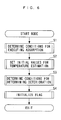
- a start mode process will be first described with reference to Fig. 6.
- the start mode process is executed only once immediately after an ignition switch (not shown) is turned ON. It is first determined at step 1 (labeled as "S1" in the figure. The same applies to the following description), whether or not conditions are established for the adsorbent 16 to adsorb hydrocarbons in exhaust gases, i.e., conditions for switching the flow passage switching valve 17 to the bypass position. Details of this operation will be described later.
- step 2 the ECU 20 sets a variety of initial values for use in estimating (calculating) the temperature of the exhaust system 3. Details of this operation will be described later as well.
- step 3 it is determined whether or not conditions are established for determining a deterioration of the adsorbent 16. Details of this operation will be described later as well.
- step 4 the ECU 20 initializes a variety of flags, followed by termination of the process. Specifically, the ECU 20 sets a condensation occurrence flag F_CONDNS and a temperature estimation starting flag F_CALTTRS, later described, to "0," respectively.
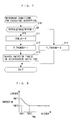
- Fig. 7 illustrates a routine for executing the processing.
- TWX the engine water temperature
- TWTRSL for example, -20°C
- TWTRSH a predetermined upper limit value
- step 10 If the result of determination at step 10 is YES, i.e., when TWTRS ⁇ TWX ⁇ TWTRSH, the routine proceeds to step 11, where the ECU 20 sets an accumulated calory value SGM_Q, later described, to zero.
- step 12 the ECU 20 sets an adsorption execution flag F_TRSRUN to "1" for indicating that the conditions are established for the adsorbent 16 to adsorb hydrocarbons.
- the routine proceeds to step 13, where the ECU 20 searches a table shown in Fig. 8 in accordance with the engine water temperature TWX to calculate a threshold TMTRSTIM for flow passage switching determination, followed by termination of the routine.
- the threshold TMTRSTIM for flow passage switching determination is used in a flow passage switching control (at step 71 in Fig. 15), later described, and more specifically, used for determining a duration in which the adsorbent 16 adsorbs hydrocarbons until the adsorbent 16 reaches the HC adsorption limit temperature, with the flow passage switching valve 17 held at the bypass position.
- the threshold TMTRSTIM for flow passage switching determination is set at a first predetermined value TMT1 when the engine water temperature TWX is at a first lattice point TWX1 or lower, at a second predetermined value TMT2 smaller than the first predetermined value TMT1 when the engine water temperature TWX is at a second lattice point TWX2, higher than the first lattice point TWX1, or higher, and at a larger value as the engine water temperature TWX is lower between the first and second predetermined values TMT1, TMT2.
- step 10 determines whether the result of determination at step 10 is NO. If the result of determination at step 10 is NO, the routine proceeds to step 14 on the assumption that the conditions are not established for the adsorbent 16 to adsorb hydrocarbons, and the ECU 20 sets the adsorption execution flag F_TRSRUN to "0" for indicating this fact, followed by termination of the routine.
- Fig. 9 illustrates a routine for executing the processing.
- the ECU 20 calculates absolute temperature converted values TW_K, TA_K which are absolute temperatures converted from the engine water temperature TWX and intake temperature TAX, respectively.
- the ECU 20 sets both an inner exhaust pipe gas temperature TEXPG[j] and an exhaust pipe wall temperature TEXPW[j] to the absolute temperature converted value TW_K of the engine water temperature TWX.
- the inner exhaust pipe gas temperature TEXPG[j] and exhaust pipe wall temperature TEXPW[j] will be described later in greater detail.
- the ECU 20 sets both an inner adsorbent gas temperature TTRSG[j] and an adsorbent temperature TTRSW[j] to a predetermined value TTRINI (for example, 338.15°K), followed by termination of the routine.
- the predetermined value TTRINI is previously set based on the temperature within the exhaust pipe 5 when condensation is eliminated.
- the inner adsorbent gas temperature TTRSG[j] and adsorbent temperature TTRSW[j] will be described later in greater detail.
- Fig. 10 illustrates a routine for executing the processing. It is first determined at step 30 whether or not an HC desorption completion flag F_HCPG is "1."
- the HC desorption completion flag F_HCPG is set to "1" when hydrocarbons are completely desorbed from the adsorbent 16, and otherwise to "1, " as will be later described, during determination on the completion of HC desorption (see Fig. 16), executed after the start of the engine 2.
- the value of the HC desorption completion flag F_HCPG is stored in a RAM having a power supply for backup, and is therefore held in the RAM even after the ignition switch is turned OFF.
- step 30 determines whether or not TWTRSL ⁇ TWX ⁇ TWTRSH is established, similarly to the aforementioned step 10.
- step 31 If the result of determination at step 31 is YES, the routine proceeds to step 32 on the assumption that the conditions are established for determining a deterioration of the adsorbent 16, and the ECU 20 sets a deterioration determination execution flag F_MCNDTRS to "1" for indicating this fact.
- the ECU 20 sets the output of the humidity sensor 21, i.e., detected relative humidity of exhaust gases (hereinafter called the "detected humidity") VHUMD as a minimum value VHUMD_MIN and the previous value VHUMD_PRE of the detected humidity.
- the humidity sensor 21 i.e., detected relative humidity of exhaust gases (hereinafter called the "detected humidity") VHUMD as a minimum value VHUMD_MIN and the previous value VHUMD_PRE of the detected humidity.
- step 35 the ECU 20 searches a table shown in Fig. 11 in accordance with the engine water temperature TWX to calculate a threshold TRSTD for deterioration determination, followed by termination of the routine.
- the threshold TRSTD for deterioration determination is used to determine whether or not the adsorbent 16 is deteriorated in deterioration determination for the adsorbent 16 (see Fig. 18), later described.
- the threshold TRSTD for deterioration determination is set at a larger value as the engine water temperature TWX is lower.
- the adsorbent 16 is at a lower temperature as the engine water temperature TWX is lower at the start of the engine 2, so that the adsorbent 16 has a higher HC adsorption performance, and the adsorbent 16 rises up to the HC adsorbent limit temperature with difficulties.
- the routine proceeds to step 36 on the assumption that the conditions are not established for determining a deterioration of the adsorbent 16, and the ECU 20 sets the deterioration determination execution flag F_MCNDTRS to "0," followed by termination of the routine.
- This routine is executed at predetermined periods (for example, every 50 msec).
- the ECU 20 estimates the temperature of the exhaust pipe 5. Details of this operation will be described later.
- step 41 it is determined whether or not a temperature estimation starting flag F_CALTTRS is "1.” If the result of determination at step 41 is NO, the routine proceeds to step 42 on the assumption that no conditions are established for estimating the temperature of the adsorbent 16, and it is determined whether or not the condensation occurrence flag F_CONDNS is "0.”
- step 42 determines whether or not the detected humidity VHUMD is higher than a threshold VWET (for example, 95 %) for determining the occurrence of condensation. If the result of determination at step 43 is NO, the routine proceeds to step 45, later described. On the other hand, if the result of determination is YES, the routine proceeds to step 44 on the assumption that condensation occurs, and the ECU 20 sets the condensation occurrence flag F_CONDNS to "1" for indicating this fact, followed by the routine proceeding to step 45. Thus, the result of determination at step 42 is NO in subsequent loops, in which case the routine proceeds to step 45.
- a threshold VWET for example, 95 %
- step 45 subsequent to steps 42 - 44, it is determined whether or not the condensation occurrence flag F_CONDNS is "1." If the result of determination at step 45 is NO, i.e., when condensation has never occurred even once after the start of the engine 2, the routine is terminated without further processing.
- step 45 determines whether or not the detected humidity VHUMD is lower than a threshold VDRY (for example, 20 %) for condensation elimination determination. If the result of determination at step 46 is NO, the routine is terminated without further processing.
- the routine proceeds to step 47 on the assumption that conditions are established for estimating the temperature of the adsorbent 16, and the ECU 20 sets the temperature estimation starting flag F_CALTTRS to "1" for indicating this fact, followed by termination of the routine.
- the result of determination at step 41 is YES in subsequent loops, in which case the routine proceeds to step 48, where the ECU 20 estimates the temperature of the adsorbent 16, as later described, followed by termination of the routine.
- Fig. 13 illustrates a routine for executing the processing.
- this routine calculates the inner exhaust pipe gas temperatures TEXPG[j] and exhaust pipe wall temperatures TEXPW[j] (upstream temperatures), respectively.
- These inner exhaust pipe gas temperatures TEXPG[j] and exhaust pipe wall temperatures TEXPW[j] indicate values at seven locations on the exhaust pipe 5 from the vicinity of the exhaust port to the vicinity of the communication holes 15b, where a larger value of j indicates a location more downstream of the exhaust pipe 5.
- TEXPG[7] and TEXPW[7] indicate values near the communication holes 15b, respectively.
- the locations at which the inner exhaust pipe gas temperature TEXPG[j] and exhaust pipe wall temperature TEXPW[j] are calculated are not limited to seven, but may be increased or decreased as appropriate.
- the ECU 20 first calculate an exhaust flow velocity KEXPV at step 50.
- the exhaust flow velocity KEXPV corresponds to a coefficient (v ⁇ t/ ⁇ x) in the second term of the right side of the equation (7) in Fig. 5.
- the exhaust flow velocity KEXPV is calculated in accordance with the engine rotational speed NE and absolute intake pipe inner pressure PBA by searching a map, not shown. In this map, the exhaust flow velocity KEXPV is set at a larger value as the engine rotational speed NE is higher or the absolute intake pipe inner pressure PBA is higher.
- the exhaust flow velocity KEXPV may be calculated by a predetermined equation in accordance with the engine rotational speed NE and absolute intake pipe inner pressure PBA.
- step 51 the ECU 20 calculates a current value TEXPG[j] of the inner exhaust pipe gas temperature and a current value TEXPW[j] of the exhaust pipe wall temperature in accordance with the following equations (9), (10), using the absolute temperature converted value TA_K of the intake temperature and the exhaust flow velocity KEXPV calculated at steps 20, 50, respectively.
- the equations (9), (10) corresponds to the aforementioned equations (7), (8) in Fig.
- TEXPG[j] TEXPG[j] n-1 - KEXPV ⁇ (TEXPG[j] n-1 - TEXPG[j-1] n-1 ) + KEXPA ⁇ (TEXPW[j] n-1 - TEXPG[j] n-1 )
- TEXPW[j] TEXPW[j] n-1 + KEXPB ⁇ (TEXPG[j] n-1 - TEXPW[j] n-1 ) + KEXPC ⁇ (TA_K - TEXPW[j] n-1 )
- j is an integer from 2 to 7
- TEXPG[j] n-1 and TEXPW[j] n-1 are the previous values of the inner exhaust pipe gas temperature and exhaust pipe wall temperature, respectively
- KEXPA, KEXPB, KEXPC are previously set constants, respectively, which corresponds to a coefficient (a ⁇ t) in the third
- step 52 the ECU 20 sets an engine exit gas temperature (the temperature of exhaust gases near the exhaust port) TEX stored in the RAM as a previous value TEX_PRE of the engine exit gas temperature.
- step 53 the ECU 20 searches a map, not shown, in accordance with the engine rotational speed NE and absolute intake air inner pressure PBA to calculate a map value TEX_MAP of the engine exit gas temperature.
- step 54 the ECU 20 calculates a current value TEX of the engine exit temperature in accordance with the following equation (11) using TEX_PRE and TEX_MAP calculated at steps 52, 53, respectively:
- TEX CKTEX ⁇ TEX_MAP + (1-CKTEX) ⁇ TEX_PRE
- CKTEX is a weighting coefficient which is set at a predetermined value larger than zero and smaller than one.
- step 55 the ECU 20 sets the current value TEX of the engine exit temperature calculated at step 54 as an inner exhaust pipe gas temperature TEXPG[1] (temperature of exhaust gases near the exhaust port of the exhaust pipe 5), followed by termination of the routine.
- Fig. 14 illustrates a routine for executing the processing.
- this routine calculates the inner adsorbent gas temperature TTRSG[j] and adsorbent temperature TTRSW[j], respectively, in a similar technique as that used for calculating the aforementioned inner exhaust pipe gas temperature TEXPG[j] and intake pipe wall temperature TEXPW[j].
- These inner adsorbent gas temperatures TTRSG[j] and adsorbent temperatures TTRSW[j] indicate values at seven locations, respectively, on the exhaust pipe 5 from the end of the adsorbent 16 close to the communication holes 15b to the end of the adsorbent 16 close to the EGR pipe 19, where a larger value of j indicates a location more downstream of the adsorbent, i.e., closer to the EGR pipe 19.
- TTRSG[7] and TTRSW[7] indicate values at the end of the adsorbent 16 close to the EGR pipe 19, respectively. It should be noted that the locations at which the inner adsorbent gas temperatures TTRSG[j] and adsorbent temperatures TTRSW[j] are calculated are not limited to seven, but may be increased or decreased as appropriate.
- the ECU 20 first calculates an exhaust flow velocity KTRSV within the adsorbent 16.
- the exhaust flow velocity KTRSV is the flow velocity of EGR gases flowing through the adsorbent 16 which is calculated by searching a map (not shown) or in accordance with an equation (not shown) in accordance with a parameter indicative of an exhaust gas flow rate (for example, the engine rotational speed NE, absolute intake air inner pressure PBA, or the like), the fuel injection amount, an EGR recirculation rate, and the like.
- step 61 the ECU 20 calculates a current value TTRSG[j] of the inner adsorbent gas temperature and a current value TTRSW[j] of the adsorbent temperature in accordance with the following equations (12), (13), substantially similar to the aforementioned equations (9), (10), using the exhaust gas temperature TEXPW[7] and exhaust flow velocity KTRSV calculated at steps 51, 60, respectively:
- TTRSG[j] TTRSG[j] n-1 - KTRSV ⁇ (TTRSG[j] n-1 - TTRSG[j-1] n-1 ) + KTRSA ⁇ (TTRSW[j] n-1 - TTRSG[j] n-1 )
- TTRSW[j] TTRSW[j] n-1 + KTRSB ⁇ (TTRSG[j] n-1 - TTRSW[j] n-1 ) + KTRSC ⁇ (TEXPW[7] - TTRSW[j]
- step 62 the ECU 20 sets TEXPG[7] (the exhaust gas temperature near the communication holes 15b) calculated at step 51 is set as TTRSG[1] (the inner adsorbent gas temperature at the end of the adsorbent 16 close to the communication holes 15b).
- step 63 the ECU 20 sets TTRSW[7] (adsorbent temperature at the end of the adsorbent 16 close to the EGR pipe 19) calculated at step 51 as a final estimated adsorbent temperature TTRS (temperature of the exhaust device), followed by termination of the routine.
- TTRSW[7] adsorbent temperature at the end of the adsorbent 16 close to the EGR pipe 19
- This routine is executed at predetermined periods (for example, every 100 msec).
- step 70 It is first determined at step 70 whether or not the adsorption execution flag F_TRSRUN is "1." If the result of determination at step 70 is NO, the routine is terminated. On the other hand, if the result of determination at step 70 is YES, i.e., when conditions are established for the adsorbent 16 to adsorb hydrocarbons, the routine proceeds to step 71, where the ECU controls the flow passage switching valve 17.
- the ECU 20 switches the flow passage switching valve 17 based on the accumulated calory value SGM_Q in the following manner.
- the accumulated calory value SGM_Q indicates an accumulated value (total sum) of calory supplied to the exhaust system 3 after the start of the engine 2, and is calculated based on an accumulated amount of fuel injected from the injector 9.
- the flow passage switching valve 17 is switched to the bypass position until the accumulated calory amount SGM_Q reaches a threshold TMTRSTIM for flow passage switching determination, calculated at the aforementioned step 13 (i.e., until the adsorbent 16 reaches the HC adsorption limit temperature), whereby hydrocarbons in exhaust gases are adsorbed to the adsorbent 16. Then, as the accumulated calory amount SGM_Q reaches the threshold TMTRSTIM for flow passage switching determination, the ECU 20 switches the flow passage switching valve 17 to the main position, so that the adsorbent 16 subsequently does not adsorb hydrocarbons.
- step 72 the ECU 20 determines the completion of desorption of hydrocarbons from the adsorbent 16. This determination on the complete desorption will be described later in greater detail.
- step 73 the ECU 20 determines a deterioration of the adsorbent 16, followed by termination of the routine. The determination on a deterioration of the adsorbent 16 will be described later in greater detail.
- the ECU 20 calculates a threshold TTRSHCPG for desorption completion determination by searching a table shown in Fig. 17 in accordance with a timer value TMACR of a post-start timer.
- the post-start timer is of a up-count type for measuring a time after the start of the engine 2, i.e., after the ignition switch is turned ON.
- the threshold TTRSHCPG for desorption completion determination is set at a first predetermined temperature TTRSHCPG1 (for example, 220 ° C) when the timer value TMARC is equal to or smaller than a first predetermined value TMACR1 (for example, 200 sec), and at a second predetermined temperature TTRSHCPG2 lower than the first predetermined temperature TTRSHCPG1 (for example, 170 °C) when the timer value is equal to or larger than a second predetermined value TMACR2 larger than the first predetermined value TTRSHCPG1 (for example, 600 sec).
- a first predetermined temperature TTRSHCPG1 for example, 220 ° C
- TMACR1 for example, 200 sec
- a second predetermined temperature TTRSHCPG2 lower than the first predetermined temperature TTRSHCPG1 for example, 170 °C
- the threshold TTRSHCPG for desorption completion determination is set at a larger value as the timer value TMACR is smaller. This setting is made for the following reason. The heat conducts less in the radial direction of the adsorbent 16 in a shorter time after the start of the engine, so that complete desorption of hydrocarbons is determined without fail, using the table shown in Fig. 17 while compensating for the thermal conduction.
- step 81 it is determined whether or not the estimated adsorbent temperature TTRS calculated at step 63 is higher than the threshold TTRSHCPG calculated at step 80. If the result of determination at step 80 is NO, the routine proceeds to step 82 on the assumption that hydrocarbons have not been completely desorbed from the adsorbent 16, and the ECU 20 sets the HC desorption completion flag F_HCPG to "0," followed by termination of the routine.
- step 81 determines whether the result of determination at step 81 is YES. If the result of determination at step 81 is YES, the routine proceeds to step 83 on the assumption that hydrocarbons have been completely desorbed from the adsorbent 16, and the ECU 20 sets the HC desorption completion flag F_HCG to "1" for indicating this fact, followed by termination of the routine.
- Fig. 18 illustrates a routine for executing the processing.
- step 90 It is first determined at step 90 whether or not the deterioration determination execution flag F_MCNDTRS is "1.” If the result of determination at step 90 is NO, the routine is terminated without further processing. On the other hand, if the result of determination at step 90 is YES, i.e., when conditions are established for determining a deterioration of the adsorbent 16, the routine proceeds to step 91, where it is determined whether or not a detected humidity VHUMD is lower than its previous value VHUMD_PRE.
- step 91 determines whether the result of determination at step 91 is NO, i.e., when the detected humidity VHUMD has increased, the routine proceeds to step 93, later described.
- the routine proceeds to step 92, where the ECU 20 sets the detected humidity VHUMD as its minimum value VHUMD_MIN, followed by the routine proceeding to step 93.
- the ECU 20 sets the detected humidity VHUMD as the previous value VHUMD_PRE.
- step 94 it is determined whether or not the detected humidity VHUMD is higher than the sum of the minimum value VHUMD_MIN of the detected humidity and a predetermined addition term VHUMD_JUD for determination. If the result of determination at step 94 is NO, the routine proceeds to step 95 on the assumption that the detected humidity VHUMD has not risen, and the ECU 20 sets a humidity rising flag F_HUML2H to "0" for indicating this fact, followed by termination of the routine.
- step 94 determines whether the result of determination at step 94 is YES. If the result of determination at step 94 is YES, the routine proceeds to step 96 on the assumption that the detected humidity VHUMD has risen, and the ECU 20 sets the humidity rising flag F_HUML2H to "1" for indicating this fact.
- step 97 it is determined whether or not the accumulated calory value SGM_Q is smaller than the threshold TRSTD for deterioration determination calculated at step 35. If the result of determination at step 97 is YES, i.e., when the detected humidity VHUMD rises though the adsorbent 16 has been given small amount of calory and its temperature has not increased, the routine proceeds to step 99 on the assumption that the adsorbent 16 is deteriorated, and the ECU 20 sets a deterioration establishment flag F_TRSDT to "1" for indicating this fact.
- step 100 the ECU 20 sets the deterioration determination execution flag F_MCNDTRS to "0," followed by termination of the routine.
- the result of determination at step 90 is NO in subsequent loops, in which case steps 91 to 100 are not executed.
- step 97 determines whether the result of determination at step 97 is NO, i.e., when the detected humidity VHUMD rises due to a large amount of calory supplied to the adsorbent 16, the temperature of which is therefore increased.
- the routine proceeds to step 98 on the assumption that the adsorbent 16 is not deteriorated, and the ECU 20 sets the deterioration establishment flag F_TRSDT to "0" for indicating this fact.
- the ECU 20 executes step 100, followed by termination of the routine.
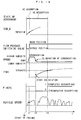
- Fig. 19 illustrates an exemplary operation of the engine when it is started, provided by the foregoing control.
- the ECU 20 switches the flow passage switching valve 17 to the bypass position, causing the adsorbent 16 to adsorb hydrocarbons.
- the accumulated calory value SGM_Q is increased to increase the temperature of the adsorbent 16, causing the amount of moisture adsorbed to the adsorbent 16 to exceed the adsorbing capability of the adsorbent 16. Consequently, the detected humidity VHUMD rises. If the HC desorption completion flag F_HCPG has been set to "1" upon the previous start of the engine 2 when the detected humidity VHUMD rises, the ECU 20 determines a deterioration of the adsorbent 16.
- condensation occurs within the exhaust pipe 5, and the accumulated calory value SGM_Q exceeds the threshold TMTRSTIM for flow passage switching determination at time t1, at which the ECU 20 switches the flow passage switching valve 17 from the bypass position to the main position, and starts the EGR operation, whereby hydrocarbons begin desorbing from the adsorbent 16, and the temperature of the exhaust pipe 5 increased so that the condensation begins disappearing.
- the ECU 20 starts calculating the estimated adsorbent temperature TTRS.
- the estimated adsorbent temperature TTRS exceeds the threshold TTRSHCPG for HC desorption completion determination, i.e., at the time hydrocarbons have completely desorbed from the adsorbent 16
- the ECU 20 sets the HC desorption completion flag F_HCPG to "1" for indicating this fact. This causes the ECU 20 to determine a deterioration of the adsorbent 16 when the detected humidity VHUMD rises at the next start of the engine 2.
- the temperature estimating apparatus 1 begins estimating the temperature of the adsorbent 16, upon elimination of condensation which has occurred at least once after the start of the engine 2, using the previously set predetermined value TTRSINI based on the temperature at which condensation is eliminated. Therefore, the temperature estimating apparatus 1 can correctly calculate and estimate the temperature of the adsorbent 16 while securely avoiding the influence of condensation even when the engine 2 is started under a low temperature condition.
- the temperature estimating apparatus 1 calculates the temperature of the exhaust pipe 5 between the adsorbent 16 and the engine 2 located upstream of the adsorbent 16, and the temperature of exhaust gases, and calculates the temperature of exhaust gases flowing through the adsorbent 16 and the temperature of the adsorbent 16, respectively, in accordance with the calculated temperatures of the exhaust pipe 5 and exhaust gases, thereby making it possible to calculate the temperature of the adsorbent 16, taking into account a change in temperature of the exhaust pipe 5 due to heat exchange with the exhaust gases, to further improve the accuracy of calculation.
- the temperature estimating apparatus 1 can correctly calculate the temperature of the adsorbent 16 as described above, it is possible to accurately determine whether or not hydrocarbons have been completely desorbed from the adsorbent 16 in accordance with the calculated temperature of the adsorbent 16. Consequently, the humidity sensor 21 can be determined in regard to a deterioration while avoiding the influence of incomplete desorption of hydrocarbons from the adsorbent 16 on the humidity of exhaust gases, to improve the accuracy of determination.
- an object the temperature of which is estimated by the temperature estimating apparatus 1 of the present invention, is not limited to the adsorbent 16 in the foregoing embodiment, but may be any exhaust device for purifying exhaust gases in the exhaust system, for example, a three-way catalyst.
- the temperature estimating apparatus for an internal combustion engine can correctly calculate and estimate the temperature of an exhaust device even when the internal combustion engine is started under a low temperature condition.
- a temperature estimating apparatus for an internal combustion engine for correctly calculating the temperature of an exhaust device even when the internal combustion engine is started under low temperature conditions.
- the temperature estimating apparatus comprises an ECU for estimating the temperature of a hydrocarbon adsorbent in an exhaust system of the internal combustion engine through calculations.
- the ECU calculates an estimated adsorbent temperature of the adsorbent in accordance with an engine rotational speed, an absolute intake pipe inner pressure, an engine water temperature, an intake temperature, and a detected humidity of exhaust gases. This calculation is started when condensation, which has occurred within an intake pipe, is eliminated.
Abstract
Description
- The present invention relates to a temperature estimating apparatus for an internal combustion engine which estimates the temperature of an exhaust device such as a catalyzer arranged in an exhaust system through calculations.
- Conventionally, one type of known temperature estimating apparatus mentioned above thermodynamically calculates the temperature of an exhaust device in an exhaust system of an internal combustion engine. More specifically, the exhaust device is thermodynamically modeled to estimate a heat exchanging state between the exhaust device and exhaust gases to calculate the temperature of the exhaust device. The temperature of the exhaust device is estimated in this manner because a detecting device such as a temperature sensor is relatively expensive to cause an increase in the manufacturing cost, in addition to its low responsibility. Thus, the temperature estimating apparatus avoids such problems to increase the responsibility in detecting the temperature and reduce the manufacturing cost.
- The conventional temperature estimating apparatus could fail to correctly calculate the temperature of the exhaust device when the internal combustion engine is started under a low temperature condition for reasons set forth below. When the internal combustion engine is started at a low ambient temperature which causes a cold exhaust pipe in an exhaust system, the saturated steam pressure of exhaust gases becomes lower associated with a reduction in the temperature of the exhaust gases passing through the exhaust device, thereby possibly resulting in condensation of moisture contained in the exhaust gases on wall surfaces of the exhaust device. In this event, heat applied from the exhaust gases to condensed water is consumed for a phase change from the condensed water to stream as latent heat of vaporization, so that the exhaust device does not change in temperature. It is therefore necessary to calculate the temperature of the exhaust device in consideration of the influence of the condensed water thus produced. However, since the amount of condensed water thus produced, and a situation in which the condensed water is produced depend on external environmental conditions and an operating condition of the internal combustion engine upon starting, it is difficult to correctly reflect the influence of condensed water to the thermodynamic model due to difficulties in measurements and calculations. Consequently, the temperature of the exhaust device can be incorrectly calculated when the internal combustion engine is started under low temperature conditions.
- The present invention has been made to solve the problem as mentioned above, and it is an object of the invention to provide a temperature estimating apparatus for an internal combustion engine which is capable of correctly calculating the temperature of an exhaust device even when the internal combustion engine is started under low temperature conditions.
- To achieve the above object, the present invention provides a temperature estimating apparatus for an internal combustion engine arranged in an exhaust system of the internal combustion engine for estimating a temperature of an exhaust device for purifying exhaust gases through calculations. The temperature estimating apparatus is characterized by comprising operating condition detecting means for detecting an operating condition of the internal combustion engine, including a state of intake air; humidity detecting means for detecting a humidity of exhaust gases; and device temperature calculating means for calculating the temperature of the exhaust device in accordance with the detected operating condition of the internal combustion engine and the detected humidity of the exhaust gases.
- As described above, when the temperature of an exhaust device is calculated by a technique of thermodynamically modeling the exhaust device, condensation of moisture in exhaust gases could cause an incorrectly calculated temperature of the exhaust device when the temperature of the exhaust system is low due to a low external temperature. In contrast, the temperature estimating apparatus for an internal combustion engine of the present invention calculates the temperature of the exhaust device in accordance with a detected operating condition of the internal combustion engine, including the state of intake air, and the humidity of exhaust gases in the exhaust system. Therefore, even when the condensation is highly likely to occur due to a low external temperature, the temperature of the exhaust gas is calculated only when exhaust gases have a low humidity and are free from condensation, thereby making it possible to calculate the temperature of the exhaust device while avoiding the influence of the condensation. As a result, the temperature estimating apparatus for an internal combustion engine of the present invention can correctly calculate and estimate the temperature of the exhaust device even when the-internal combustion engine is started under a low temperature condition.
- Preferably, the temperature estimating apparatus for an internal combustion engine further comprises condensation determining means for determining whether or not condensation occurs within the exhaust system in accordance with the detected humidity of the exhaust gases, wherein the device temperature calculating means calculates the temperature of the exhaust device further in accordance with a result of determination made by the condensation determining means.
- According to this preferred embodiment of the temperature estimating apparatus for an internal combustion engine, the temperature of the exhaust device can be correctly estimated, while securely avoiding the influence of condensation, by calculating the temperature of the exhaust device only when no condensation occurs within the exhaust system in accordance with the result of determination made by the condensation determining means.
- Preferably, the temperature estimating apparatus for an internal combustion engine further comprises calculation start timing determining means for determining a timing for start calculating the temperature of the exhaust device by the device temperature calculating means in accordance with the result of determination made by the condensation determining means.
- According to this preferred embodiment of the temperature estimating apparatus for an internal combustion engine, since the device temperature calculating means can start the calculation of the temperature of the exhaust device when no condensation occurs within the exhaust system, it is possible to start calculating the temperature of the exhaust device at an optimal timing.
- Preferably, in the temperature estimating apparatus for an internal combustion engine, the device temperature calculating means calculates an upstream temperature at a location of the exhaust system upstream of the exhaust device in accordance with the operating condition of the internal combustion engine and the humidity of the exhaust gases, and calculates the temperature of the exhaust device in accordance with the calculated upstream temperature.
- Generally, in the internal combustion engine, the temperature of exhaust gases near an exhaust port can be correctly calculated in accordance with an operating condition of the internal combustion engine. As exhaust gases flow down, heat is lost due to heat exchange with the exhaust system. Taking into account these properties, the temperature estimating apparatus for an internal combustion engine of the present invention calculates the upstream temperature at a location of the exhaust system upstream of the exhaust device in accordance with the operating condition of the internal combustion engine and the humidity of exhaust gases, and calculates the temperature of the exhaust device in accordance with the upstream temperature which is calculated based on the more correct temperature of exhaust gases near the exhaust port. Thus, the temperature of the exhaust device can be calculated in consideration of a change in temperature of the exhaust system due to heat exchange with exhaust gases, at a location upstream of the exhaust device, thereby further improving the accuracy of calculation.
- Preferably, in the temperature estimating apparatus for an internal combustion engine, the exhaust device comprises a hydrocarbon adsorbent for adsorbing hydrocarbons in exhaust gases.
- This preferred embodiment of the temperature estimating apparatus for an internal combustion engine can accurately estimate the temperature of the hydrocarbon adsorbent and accordingly estimate with a high accuracy the adsorption and desorption of hydrocarbons to and from the hydrocarbon adsorbent in accordance with the estimated temperature.
- Preferably, the temperature estimating apparatus for an internal combustion engine further comprises desorption determining means for determining whether or not hydrocarbons have been completely desorbed from the hydrocarbon adsorbent in accordance with the temperature of the hydrocarbon adsorbent calculated by the device temperature calculating means.
- Generally, the hydrocarbon adsorbent has the property of substantially completely desorbing hydrocarbons when it is heated to a predetermined temperature or higher. Therefore, according to this preferred embodiment of the temperature estimating apparatus for an internal combustion engine, it is possible to correctly determine whether or not hydrocarbons have been completely desorbed from the hydrocarbon adsorbent.
-
- Fig. 1 is a diagram generally illustrating an internal combustion engine in which a temperature estimating apparatus for an internal combustion engine is applied according to one embodiment of the present invention;
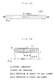
- Fig. 2 is a cross-sectional view illustrating the general configuration of an exhaust system around an adsorbent;
- Fig. 3A is a schematic diagram which thermodynamically models an exhaust pipe;
- Fig. 3B is an enlarged view of a portion of the exhaust pipe;
- Fig. 4 shows partial differential equations (1), (2) for calculating the temperature of exhaust gases and the temperature on the wall of the exhaust pipe based on the modelling illustrated in Figs. 3A and 3B;
- Fig. 5 shows dimensionless equations (3), (4) from the equations (1), (2) in Fig. 4, equations (5), (6) derived by solving the equations (3), (4) by a differential method, and approximate differential equations (7), (8) derived by solving again the equations (5), (6) for G(t+Δt,x), W(t+Δt,x), respectively;
- Fig. 6 is a flow chart illustrating a start mode process;
- Fig. 7 is a flow chart illustrating a specific routine
for determining an adsorption execution condition at
step 1 in Fig. 6; - Fig. 8 shows an exemplary table for use in a calculation of a threshold TMTRSTIM for determining switching of a flow passage;
- Fig. 9 is a flow chart illustrating a routine for
executing the processing at
step 2 in Fig. 6 for setting initial values for temperature estimation; - Fig. 10 is a flow chart illustrating a routine for
executing the processing at
step 3 in Fig. 6 for determining a deterioration determination execution condition; - Fig. 11 shows an exemplary table for use in a calculation of a threshold TRSTD for deterioration determination;
- Fig. 12 is a flow chart illustrating a main routine for estimating the temperature of an exhaust system;
- Fig. 13 is a flow chart illustrating a routine for
executing the processing at
step 40 in Fig. 12 for estimating the temperature of an exhaust pipe; - Fig. 14 is a flow chart illustrating a routine for executing the processing at step at 48 in Fig. 12 for estimating the temperature of the adsorbent;
- Fig. 15 is a flow chart illustrating a main routine for controlling an HC adsorber;
- Fig. 16 is a flow chart illustrating a routine for executing the processing at step 72 in Fig. 15 for determining completion of HC desorption from the adsorbent;
- Fig. 17 shows an exemplary table for use in a calculation of a threshold TTRSHCPG for determination on completion of HC desorption;
- Fig. 18 is a flow chart illustrating a routine for executing the processing at step 73 in Fig. 15 for determining a deterioration of the adsorbent; and
- Fig. 19 is a timing chart illustrating an exemplary operation of the engine when it is started.
-
- In the following, a temperature estimating apparatus for an internal combustion engine according to one embodiment of the present invention will be described with reference to the accompanying drawings. Fig. 1 generally illustrates the configuration of the temperature estimating apparatus according to this embodiment, and an internal combustion engine in which the temperature estimating apparatus is applied. As described later, the
temperature estimating apparatus 1 relies on calculations to estimate the temperature of a hydrocarbon adsorbent (hereinafter called the "adsorbent") 16 as an exhaust device arranged in anexhaust system 3 of the internal combustion engine (hereinafter called the "engine") 2. - An
exhaust pipe 5 is connected to theengine 2 through anexhaust manifold 5a. Acatalyzer 7 having two three-way catalysts 6, and a hydrocarbon (hereinafter called "HC") adsorber 10 for adsorbing and processing hydrocarbons are provided halfway in theexhaust pipe 5 in this order from the upstream side. The three-way catalysts 6 are arranged adjacent to each other along theexhaust pipe 5, and purify harmful substances (hydrocarbons (HC), carbon monoxide (CO) and nitrogen oxides (NOx)) in exhaust gases passing through thecatalyzer 7 by oxidation-reduction catalyst actions, when they are activated. The three-way catalysts 6 begin activations at a predetermined activation starting temperature (for example, 100 °C) or higher, and are completely activated when they reach a higher complete activation temperature (for example 300 °C). - The
HC adsorber 10 in turn adsorbs hydrocarbons in exhaust gases until the respective three-way catalysts 6 reach the activation starting temperature after a start of the engine to prevent hydrocarbons in exhaust gases from being emitted to the atmosphere, as will be later described. - As illustrated in Fig. 2, the
HC adsorber 10 comprises anelongated case 11; amain exhaust passage 14 having an annular cross-section and formed within thecase 11; abypass exhaust passage 15 formed within themain exhaust passage 14, and once branched from themain exhaust passage 14 and again joined thereto; an adsorbent 16 arranged in thebypass exhaust passage 15; and a flowpassage switching valve 17 for switching a flow passage of exhaust gases within the hydrocarbons adsorber 10 to either themain exhaust passage 14 or thebypass exhaust passage 15. - The
case 11 has abranch case 12 and a downstreamjoint case 13 which are arranged side by side and assembled into thecase 11. Bothbranch case 12 andjoint case 13 are made of a metal (for example, stainless steel). Themain exhaust passage 14 extends through thebranch case 12, with an upstream end of thebypass exhaust passage 15 branching from an upstream end of themain exhaust passage 14. - The flow
passage switching valve 17 is arranged at a location within thebranch case 12 at which thebypass exhaust passage 15 is branched from themain exhaust passage 14 for pivotal movements about a horizontal axis. Specifically, the flowpassage switching valve 17 is pivotable between a main position (indicated by solid line in Fig. 2) at which the flowpassage switching valve 17 closes thebypass exhaust passage 15 and simultaneously opens themain exhaust passage 14, and a bypass position (indicated by two-dot chain lines in Fig. 2) at which the flowpassage switching valve 17 closes themain exhaust passage 14 and simultaneously opens thebypass exhaust passage 15. - An
electromagnetic actuator 18 and a twisted coil spring (not shown) are attached to thebranch case 12 for driving the flowpassage switching valve 17 to switch the exhaust gas passage. Theelectromagnetic actuator 18 is electrically connected to anECU 20, later described, and is controlled ON/OFF by a driving signal from theECU 20 to drive the flowpassage switching valve 17 between the main position and bypass position in cooperation with the twisted coil spring. Specifically, theelectromagnetic actuator 18 holds the flowpassage switching valve 17 at the main position by an urging force of the twisted coil spring when it is turned OFF, and drives the flowpassage switching valve 17 from the main position to the bypass position against the urging force of the twisted coil spring when it is turned ON. - One end of an
EGR pipe 19 is connected to an intermediate location of thebypass exhaust passage 15 in thebranch case 12. The other end of theEGR pipe 19 is connected to anintake pipe 8. A duty control valve, not shown, is also arranged halfway in theEGR pipe 19, such that the amount of exhaust gases (EGR amount) recirculated to theintake pipe 8 is controlled by the duty control valve under the control of theECU 20. - The
joint case 13 comprises a larger cylinder 13a formed concentrically with thebypass exhaust passage 15, and asmaller cylinder 13b connected to an upstream end of the larger cylinder 13a. The larger cylinder 13a is tapered toward the upstream end and downstream end. Thebypass exhaust passage 15 has apassage wall 15a made of a metal having a high thermal conductivity (for example, stainless steel), and is similar to the larger cylinder 13a in that it is cylindrical and tapered toward the upstream end and downstream end. An upstream end and a downstream end of thepassage wall 15a are connected to the inner surface of thejoint case 13 in an air tight state. Thepassage wall 15a is formed with fiveoval communication holes 15a arranged at regular intervals in the circumferential direction in a lower end portion. - The
bypass exhaust passage 15 in thejoint case 13 is continuous to thebypass exhaust passage 15 of thebranch case 12 and to thedownstream exhaust pipe 5. On the other hand, themain exhaust passage 14 in thejoint case 13 comprises a flow-inpassage 14b extending into thesmaller cylinder 13b, and anannular passage 14a which is continuous to the flow-inpassage 14b, extends into the larger cylinder 13a, and closely surrounds thebypass exhaust passage 15. An upstream end of the flow-inpassage 14b is continuous to themain exhaust passage 14 of thebranch case 12, while a downstream end of theannular passage 14a joins to a downstream end of thebypass exhaust passage 15 through the communication holes 15b. - The adsorbent 16 is fully filled in the
bypass exhaust passage 15 except for the upstream and downstream ends. The adsorbent 16 is comprised of a honeycomb core (not shown), made of a metal (for example, stainless steel), which carries zeolite on its surface, and comprises a large number of inner pores (not shown) extending therethrough along thebypass exhaust passage 15. When exhaust gases introduced into thebypass exhaust passage 15 pass through the inner pores of the adsorbent 16, hydrocarbons and moisture in the exhaust gases are adsorbed by the zeolite. - The zeolite, which has high heat resistant properties, adsorbs hydrocarbons at lower than a predetermined desorption starting temperature (for example, 100 °C), starts desorbing hydrocarbons adsorbed thereby at the desorption starting temperature or higher, and completely desorbs the adsorbed hydrocarbons at a predetermined complete desorption temperature (for example, 200 °C) or higher. The hydrocarbons desorbed from the zeolite are recirculated to the
intake pipe 8 through theEGR pipe 19 and burnt in theengine 2. It should be noted that the zeolite is only required to have the ability of adsorbing hydrocarbons and is not particularly limited in type. This embodiment employs a mixture of USY (Y-type), Ga-MFI and ferrierite. - In the
HC adsorber 10 configured as described above, the flowpassage switching valve 17 is driven from the main position to the bypass position by theelectromagnetic actuator 18 after the start of theengine 2, as will be later described. Consequently, exhaust gases passing through thecatalyzer 7 are introduced into thebypass exhaust passage 15, and emitted to the outside through theexhaust pipe 5 after hydrocarbons and moisture contained therein are adsorbed by the adsorbent 16. Then, at the time the adsorbent 16 is estimated to reach an HC adsorption limit temperature, the flowpassage switching valve 17 is driven from the bypass position to the main position, and an EGR operation is carried out, thereby causing hydrocarbons adsorbed on the adsorbent 16 to start desorbing through a heat exchange produced by the exhaust gases passing through the adsorbent 16. Then, hydrocarbons desorbed from the adsorbent 16 are recirculated to theintake pipe 8 through theEGR pipe 19 together with EGR gases (recirculated exhaust gases), and burnt by theengine 2. Subsequently, as the adsorbent 16 is heated to the complete desorption temperature or higher, hydrocarbons are completely desorbed from the adsorbent 16. - The
intake pipe 8 is connected to one of a plurality of cylinders (only one of which is shown) of theengine 2 through one of a plurality of branches (only one of which is shown) of an intake manifold 8a. Aninjector 9 is attached to each branch to face an intake port of an associated cylinder. Eachinjector 9 is driven by a driving signal from theECU 20 upon start of theengine 2 to inject a fuel into an intake port in an associated branch. - The
temperature estimating apparatus 1 comprises ahumidity sensor 21; awater temperature sensor 22; acrank angle sensor 23; an absolute intake pipeinner pressure sensor 24; anintake temperature sensor 25; theECU 20; and the like (see Fig. 1). The humidity sensor 21 (humidity detecting means) is attached to the downstream end of thejoint case 13 such that adetector 21a at a leading end thereof faces thebypass exhaust passage 15 through one of the communication holes 15b. Thehumidity sensor 21 detects a relative humidity VHUMD of exhaust gasses which have passed the adsorbent 16 and outputs a detection signal indicative of the relative humidity VHUMD to theECU 20. Though detailed description is omitted here, thehumidity sensor 21 is configured in a manner similar to that proposed by the Applicant in Japanese Patent Application No. 2000-23085. - The water temperature sensor 22 (operating condition detecting means) comprises a thermistor attached to the body of the
engine 2, and detects an engine water temperature TWX, which is the temperature of cooling water circulating within a cylinder block of theengine 2, and outputs a detection signal indicative of the engine water temperature TXW to theECU 20. - The crank angle sensor 23 (operating condition detecting means) is arranged on a crank shaft of the
engine 2, and outputs a CRK signal and a TDC signal, both of which are pulse signals, to theECU 20 as the crank shaft is rotated. - One pulse of the CRK signal is outputted every predetermined crank angle (for example, 30°). The
ECU 20 calculates a rotational speed of the engine 2 (hereinafter called the "engine rotational speed") NE in response to the CRK signal. The TDC signal indicates that a piston of each cylinder is at a predetermined crank angle position slightly before the TDC position of an intake stroke, and one pulse is outputted every predetermined crank angle. - The absolute intake pipe inner pressure sensor 24 (operating condition detecting means) and intake temperature sensor 25 (operating condition detecting means) are arranged at locations downstream and upstream of a throttle valve in the
intake pipe 8, respectively. The absolute intake pipeinner pressure sensor 24, which comprises, for example, a semiconductor pressure sensor or the like, detects an absolute intake pipe inner pressure PBA within theintake pipe 8, and outputs a detection signal indicative of the absolute intake pipe inner pressure PBA to theECU 20. Theintake temperature sensor 25, on the other hand, comprises a thermistor or the like, detects an intake temperature TAX within theintake pipe 8, and sends a detection signal indicative of the intake temperature TAX to theECU 20. - The
ECU 20 is based on a microcomputer which comprises an I/O interface, a CPU, a RAM, a ROM and the like, and determines an operating condition of theengine 2 in accordance with a control program stored in the ROM and the like in response to detection signals from a variety of the aforementioned sensors 21 - 25, as well as executes the calculation of the temperature of the adsorbent 16, determination as to whether hydrocarbons are desorbed from the adsorbent 16, determination on a deterioration of the adsorbent 16, and the like, in accordance with a determined operating condition, as will be later described. - Next, the principles of a technique for calculating (estimating) the temperature of the adsorbent 16 in this embodiment will be described with reference to Figs. 3 to 5. In the following description, assume that the
exhaust manifold 5a andcase 11 are included in theexhaust pipe 5, and collectively referred to as theexhaust pipe 5. - In the calculation technique, a portion of the
exhaust pipe 5 from the vicinity of an exhaust port to the vicinity of thecommunication holes 15b is assumed to be straight, as illustrated in Figs. 3A and 3B, and thermodynamically modeled under the following conditions (1) - (5): ' - (1) An exhaust gas element moves by Vdz in a z-direction
for dt time while exchanging heat with the
wall 5b of the exhaust pipe 5 (hereinafter called the "exhaust pipe wall"), and the exhaust gas element changes in temperature by dt. - (2) The exhaust gas temperature and the temperature on
the
exhaust pipe wall 5b (hereinafter called the "exhaust pipe wall temperature") are functions of time t and location z. - (3) A thermal conductivity between exhaust gases and
exhaust pipe wall 5b, and a thermal conductivity between theexhaust pipe wall 5b and external air are proportional to a difference in temperature therebetween (Newton's law of cooling). - (4) A thermal conductivity in the radial direction of
the
exhaust pipe wall 5b is assumed to be infinite (in other words, assume that there is no temperature distribution in the radial direction). - (5) A thermal conductivity of the
exhaust pipe wall 5b in the longitudinal direction is assumed to be zero (in other words, assume that no heat is conducted between adjacent elements ofexhaust pipe wall 5b). -
- Taking into account the foregoing conditions (1) - (5), the thermal exchanges between exhaust gases in the exhaust pipe and the
exhaust pipe wall 5b are represented by equation (1) shown in Fig. 4 for the exhaust gases, and by equation (2) shown in Fig. 4 for theexhaust pipe wall 5b. These equations (1), (2) are transformed into dimensionless forms as represented by equations (3), (4) shown in Fig. 5, respectively. - Next, the equations (3), (4) are solved by a differential method in consideration of differential equations corresponding to these equations (3), (4) to derive equations (5), (6), respectively, shown in Fig. 5. These equations (5), (6) are further solved again for G(t+Δt,x), W(t+Δt,x), respectively, to derive equations (7), (8), respectively, shown in Fig. 5. These equations (7), (8) are differential equations approximate to partial differential equations (3), (4), respectively.
- It can be understood with reference to the equations (7), (8) that both dimensionless temperature converted values G(t+Δt,x), W(t+Δt,x) can be calculated at any position x at time t+Δt by finding dimensionless temperature converted values G(t,x), W(t,x) of the exhaust gas temperature TG and exhaust pipe wall temperature TW at any position x at arbitrary time t. Accordingly, by appropriately setting initial values (for example, predetermined values for a start of the engine) for both dimensionless temperature converted values G(t,x), W(t,x), the dimensionless temperature converted values G(t,x), W(t,x) of the exhaust gas temperature TG and exhaust pipe wall temperature TW can be respectively calculated subsequently at any position x.
- Further, though detailed description is omitted, a similar technique can be applied for calculating an inside adsorbent gas temperature, which is the temperature of exhaust gases within the adsorbent 16, and an adsorbent temperature which is the temperature of the adsorbent 16. In this event, the dimensionless temperature converted values of the inside adsorbent gas temperature and adsorbent temperature can be calculated respectively at any position from the end of the adsorbent 16 close to the communication holes 15b to the end of the adsorbent 16 close to the
EGR pipe 19 by setting as initial values the dimensionless temperature converted values G(t,x), W(t,x) of the exhaust gas temperature TG and exhaust pipe wall temperature TW near the communication holes 15b. - The following description will be centered on a variety of controls executed by the
ECU 20. A start mode process will be first described with reference to Fig. 6. The start mode process is executed only once immediately after an ignition switch (not shown) is turned ON. It is first determined at step 1 (labeled as "S1" in the figure. The same applies to the following description), whether or not conditions are established for the adsorbent 16 to adsorb hydrocarbons in exhaust gases, i.e., conditions for switching the flowpassage switching valve 17 to the bypass position. Details of this operation will be described later. - Next, the flow proceeds to step 2, where the
ECU 20 sets a variety of initial values for use in estimating (calculating) the temperature of theexhaust system 3. Details of this operation will be described later as well. - Next, the flow proceeds to step 3, where it is determined whether or not conditions are established for determining a deterioration of the adsorbent 16. Details of this operation will be described later as well.
- Next, the flow proceeds to step 4, where the
ECU 20 initializes a variety of flags, followed by termination of the process. Specifically, theECU 20 sets a condensation occurrence flag F_CONDNS and a temperature estimation starting flag F_CALTTRS, later described, to "0," respectively. - Next, the processing for determining the conditions for the adsorbent 16 to adsorb hydrocarbons at
step 1 will be described with reference to Fig. 7 which illustrates a routine for executing the processing. First, atstep 10, it is determined whether or not the engine water temperature TWX is equal to or higher than a predetermined lower limit value TWTRSL (for example, -20°C) and equal to or lower than a predetermined upper limit value TWTRSH (for example, 50 °C). - If the result of determination at
step 10 is YES, i.e., when TWTRS≦TWX≦TWTRSH, the routine proceeds to step 11, where theECU 20 sets an accumulated calory value SGM_Q, later described, to zero. - Next, the routine proceeds to step 12, where the
ECU 20 sets an adsorption execution flag F_TRSRUN to "1" for indicating that the conditions are established for the adsorbent 16 to adsorb hydrocarbons. - Next, the routine proceeds to step 13, where the
ECU 20 searches a table shown in Fig. 8 in accordance with the engine water temperature TWX to calculate a threshold TMTRSTIM for flow passage switching determination, followed by termination of the routine. The threshold TMTRSTIM for flow passage switching determination is used in a flow passage switching control (atstep 71 in Fig. 15), later described, and more specifically, used for determining a duration in which the adsorbent 16 adsorbs hydrocarbons until the adsorbent 16 reaches the HC adsorption limit temperature, with the flowpassage switching valve 17 held at the bypass position. - As shown in Fig. 8, in the table, the threshold TMTRSTIM for flow passage switching determination is set at a first predetermined value TMT1 when the engine water temperature TWX is at a first lattice point TWX1 or lower, at a second predetermined value TMT2 smaller than the first predetermined value TMT1 when the engine water temperature TWX is at a second lattice point TWX2, higher than the first lattice point TWX1, or higher, and at a larger value as the engine water temperature TWX is lower between the first and second predetermined values TMT1, TMT2. This is because the temperature of the adsorbent 16 is lower as the engine water temperature TWX is lower so that it takes a longer time for the adsorbent 16 to reach the hydrocarbons adsorption limit temperature.
- On the other hand, if the result of determination at
step 10 is NO, the routine proceeds to step 14 on the assumption that the conditions are not established for the adsorbent 16 to adsorb hydrocarbons, and theECU 20 sets the adsorption execution flag F_TRSRUN to "0" for indicating this fact, followed by termination of the routine. - Next, the processing for setting initial values for temperature estimation at
step 2 in Fig. 6 will be described with reference to Fig. 9 which illustrates a routine for executing the processing. First, atstep 20, theECU 20 calculates absolute temperature converted values TW_K, TA_K which are absolute temperatures converted from the engine water temperature TWX and intake temperature TAX, respectively. - Next, at
steps ECU 20 sets both an inner exhaust pipe gas temperature TEXPG[j] and an exhaust pipe wall temperature TEXPW[j] to the absolute temperature converted value TW_K of the engine water temperature TWX. The inner exhaust pipe gas temperature TEXPG[j] and exhaust pipe wall temperature TEXPW[j] will be described later in greater detail. - Next, at
steps ECU 20 sets both an inner adsorbent gas temperature TTRSG[j] and an adsorbent temperature TTRSW[j] to a predetermined value TTRINI (for example, 338.15°K), followed by termination of the routine. The predetermined value TTRINI is previously set based on the temperature within theexhaust pipe 5 when condensation is eliminated. The inner adsorbent gas temperature TTRSG[j] and adsorbent temperature TTRSW[j] will be described later in greater detail. - Next, the processing for determining a deterioration determination execution condition at
step 3 in Fig. 6 will be described with reference to Fig. 10 which illustrates a routine for executing the processing. It is first determined at step 30 whether or not an HC desorption completion flag F_HCPG is "1." The HC desorption completion flag F_HCPG is set to "1" when hydrocarbons are completely desorbed from the adsorbent 16, and otherwise to "1, " as will be later described, during determination on the completion of HC desorption (see Fig. 16), executed after the start of theengine 2. The value of the HC desorption completion flag F_HCPG is stored in a RAM having a power supply for backup, and is therefore held in the RAM even after the ignition switch is turned OFF. - If the result of determination at step 30 is YES, i.e., when hydrocarbons have been completely desorbed from the adsorbent 16 after the previous start of the
engine 2, the routine proceeds to step 31, where it is determined whether or not TWTRSL≦TWX≦ TWTRSH is established, similarly to theaforementioned step 10. - If the result of determination at step 31 is YES, the routine proceeds to step 32 on the assumption that the conditions are established for determining a deterioration of the adsorbent 16, and the
ECU 20 sets a deterioration determination execution flag F_MCNDTRS to "1" for indicating this fact. - Next, at steps 33, 34, the
ECU 20 sets the output of thehumidity sensor 21, i.e., detected relative humidity of exhaust gases (hereinafter called the "detected humidity") VHUMD as a minimum value VHUMD_MIN and the previous value VHUMD_PRE of the detected humidity. - Next, the routine proceeds to step 35, where the
ECU 20 searches a table shown in Fig. 11 in accordance with the engine water temperature TWX to calculate a threshold TRSTD for deterioration determination, followed by termination of the routine. The threshold TRSTD for deterioration determination is used to determine whether or not the adsorbent 16 is deteriorated in deterioration determination for the adsorbent 16 (see Fig. 18), later described. As shown in Fig. 11, in the table, the threshold TRSTD for deterioration determination is set at a larger value as the engine water temperature TWX is lower. This is because the adsorbent 16 is at a lower temperature as the engine water temperature TWX is lower at the start of theengine 2, so that the adsorbent 16 has a higher HC adsorption performance, and the adsorbent 16 rises up to the HC adsorbent limit temperature with difficulties. - On the other hand, if the result of determination at step 30 is NO, i.e., when hydrocarbons have not been completely desorbed from the adsorbent 16 after the previous start of the
engine 2, or if the result of determination at step 31 is NO, i.e., when the engine water temperature TWX is excessively high or excessively low, the routine proceeds to step 36 on the assumption that the conditions are not established for determining a deterioration of the adsorbent 16, and theECU 20 sets the deterioration determination execution flag F_MCNDTRS to "0," followed by termination of the routine. - Next, a main routine of exhaust system temperature estimation for estimating the temperature of the
exhaust system 3 will be described with reference to Fig. 12. This routine is executed at predetermined periods (for example, every 50 msec). - First, at
step 40, theECU 20 estimates the temperature of theexhaust pipe 5. Details of this operation will be described later. - Next, the routine proceeds to step 41, where it is determined whether or not a temperature estimation starting flag F_CALTTRS is "1." If the result of determination at
step 41 is NO, the routine proceeds to step 42 on the assumption that no conditions are established for estimating the temperature of the adsorbent 16, and it is determined whether or not the condensation occurrence flag F_CONDNS is "0." - If the result of determination at
step 42 is YES, i.e., when no condensation occurs after the start of theengine 2, the routine proceeds to step 43, where it is determined whether or not the detected humidity VHUMD is higher than a threshold VWET (for example, 95 %) for determining the occurrence of condensation. If the result of determination at step 43 is NO, the routine proceeds to step 45, later described. On the other hand, if the result of determination is YES, the routine proceeds to step 44 on the assumption that condensation occurs, and theECU 20 sets the condensation occurrence flag F_CONDNS to "1" for indicating this fact, followed by the routine proceeding to step 45. Thus, the result of determination atstep 42 is NO in subsequent loops, in which case the routine proceeds to step 45. - At
step 45 subsequent to steps 42 - 44, it is determined whether or not the condensation occurrence flag F_CONDNS is "1." If the result of determination atstep 45 is NO, i.e., when condensation has never occurred even once after the start of theengine 2, the routine is terminated without further processing. - On the other hand, if the result of determination at
step 45 is YES, i.e., when condensation occurs after the start of theengine 2, the routine proceeds to step 46, where it is determined whether or not the detected humidity VHUMD is lower than a threshold VDRY (for example, 20 %) for condensation elimination determination. If the result of determination atstep 46 is NO, the routine is terminated without further processing. On the other hand, if the result of determination atstep 46 is YES, i.e. , when the condensation is eliminated, the routine proceeds to step 47 on the assumption that conditions are established for estimating the temperature of the adsorbent 16, and theECU 20 sets the temperature estimation starting flag F_CALTTRS to "1" for indicating this fact, followed by termination of the routine. Thus, the result of determination atstep 41 is YES in subsequent loops, in which case the routine proceeds to step 48, where theECU 20 estimates the temperature of the adsorbent 16, as later described, followed by termination of the routine. - Next, the processing for estimating the temperature of the
exhaust pipe 5 atstep 40 in Fig. 12 will be described with reference to Fig. 13 which illustrates a routine for executing the processing. As described below, this routine calculates the inner exhaust pipe gas temperatures TEXPG[j] and exhaust pipe wall temperatures TEXPW[j] (upstream temperatures), respectively. These inner exhaust pipe gas temperatures TEXPG[j] and exhaust pipe wall temperatures TEXPW[j] indicate values at seven locations on theexhaust pipe 5 from the vicinity of the exhaust port to the vicinity of thecommunication holes 15b, where a larger value of j indicates a location more downstream of theexhaust pipe 5. Specifically, TEXPG[7] and TEXPW[7] indicate values near thecommunication holes 15b, respectively. It should be noted that the locations at which the inner exhaust pipe gas temperature TEXPG[j] and exhaust pipe wall temperature TEXPW[j] are calculated are not limited to seven, but may be increased or decreased as appropriate. - In the routine illustrated in Fig. 13, the
ECU 20 first calculate an exhaust flow velocity KEXPV atstep 50. The exhaust flow velocity KEXPV corresponds to a coefficient (v·Δt/Δx) in the second term of the right side of the equation (7) in Fig. 5. Specifically, the exhaust flow velocity KEXPV is calculated in accordance with the engine rotational speed NE and absolute intake pipe inner pressure PBA by searching a map, not shown. In this map, the exhaust flow velocity KEXPV is set at a larger value as the engine rotational speed NE is higher or the absolute intake pipe inner pressure PBA is higher. Alternatively, instead of searching the map as mentioned above, the exhaust flow velocity KEXPV may be calculated by a predetermined equation in accordance with the engine rotational speed NE and absolute intake pipe inner pressure PBA. - Next, the routine proceeds to step 51, where the
ECU 20 calculates a current value TEXPG[j] of the inner exhaust pipe gas temperature and a current value TEXPW[j] of the exhaust pipe wall temperature in accordance with the following equations (9), (10), using the absolute temperature converted value TA_K of the intake temperature and the exhaust flow velocity KEXPV calculated atsteps - Next, the routine proceeds to step 52, where the
ECU 20 sets an engine exit gas temperature (the temperature of exhaust gases near the exhaust port) TEX stored in the RAM as a previous value TEX_PRE of the engine exit gas temperature. - Next, the routine proceeds to step 53, where the
ECU 20 searches a map, not shown, in accordance with the engine rotational speed NE and absolute intake air inner pressure PBA to calculate a map value TEX_MAP of the engine exit gas temperature. - Next, the routine proceeds to step 54, where the
ECU 20 calculates a current value TEX of the engine exit temperature in accordance with the following equation (11) using TEX_PRE and TEX_MAP calculated atsteps 52, 53, respectively: - Next, the routine proceeds to step 55, where the
ECU 20 sets the current value TEX of the engine exit temperature calculated atstep 54 as an inner exhaust pipe gas temperature TEXPG[1] (temperature of exhaust gases near the exhaust port of the exhaust pipe 5), followed by termination of the routine. - Next, the processing for estimating the temperature of the adsorbent 16 at step at 48 in Fig. 12 will be described with reference to Fig. 14 which illustrates a routine for executing the processing. As described below, this routine calculates the inner adsorbent gas temperature TTRSG[j] and adsorbent temperature TTRSW[j], respectively, in a similar technique as that used for calculating the aforementioned inner exhaust pipe gas temperature TEXPG[j] and intake pipe wall temperature TEXPW[j]. These inner adsorbent gas temperatures TTRSG[j] and adsorbent temperatures TTRSW[j] indicate values at seven locations, respectively, on the
exhaust pipe 5 from the end of the adsorbent 16 close to the communication holes 15b to the end of the adsorbent 16 close to theEGR pipe 19, where a larger value of j indicates a location more downstream of the adsorbent, i.e., closer to theEGR pipe 19. Specifically, TTRSG[7] and TTRSW[7] indicate values at the end of the adsorbent 16 close to theEGR pipe 19, respectively. It should be noted that the locations at which the inner adsorbent gas temperatures TTRSG[j] and adsorbent temperatures TTRSW[j] are calculated are not limited to seven, but may be increased or decreased as appropriate. - In the routine illustrated in Fig. 14, the
ECU 20 first calculates an exhaust flow velocity KTRSV within the adsorbent 16. The exhaust flow velocity KTRSV is the flow velocity of EGR gases flowing through the adsorbent 16 which is calculated by searching a map (not shown) or in accordance with an equation (not shown) in accordance with a parameter indicative of an exhaust gas flow rate (for example, the engine rotational speed NE, absolute intake air inner pressure PBA, or the like), the fuel injection amount, an EGR recirculation rate, and the like. - Next, the routine proceeds to step 61, where the
ECU 20 calculates a current value TTRSG[j] of the inner adsorbent gas temperature and a current value TTRSW[j] of the adsorbent temperature in accordance with the following equations (12), (13), substantially similar to the aforementioned equations (9), (10), using the exhaust gas temperature TEXPW[7] and exhaust flow velocity KTRSV calculated atsteps 51, 60, respectively: - Next, the routine proceeds to step 62, where the
ECU 20 sets TEXPG[7] (the exhaust gas temperature near the communication holes 15b) calculated at step 51 is set as TTRSG[1] (the inner adsorbent gas temperature at the end of the adsorbent 16 close to the communication holes 15b). - Next, the routine proceeds to step 63, where the
ECU 20 sets TTRSW[7] (adsorbent temperature at the end of the adsorbent 16 close to the EGR pipe 19) calculated at step 51 as a final estimated adsorbent temperature TTRS (temperature of the exhaust device), followed by termination of the routine. - Next, a main routine for controlling the
HC adsorber 10 will be described with reference to Fig. 15. This routine is executed at predetermined periods (for example, every 100 msec). - It is first determined at
step 70 whether or not the adsorption execution flag F_TRSRUN is "1." If the result of determination atstep 70 is NO, the routine is terminated. On the other hand, if the result of determination atstep 70 is YES, i.e., when conditions are established for the adsorbent 16 to adsorb hydrocarbons, the routine proceeds to step 71, where the ECU controls the flowpassage switching valve 17. - Though the control of the flow
passage switching valve 17 is not illustrated, theECU 20 switches the flowpassage switching valve 17 based on the accumulated calory value SGM_Q in the following manner. The accumulated calory value SGM_Q indicates an accumulated value (total sum) of calory supplied to theexhaust system 3 after the start of theengine 2, and is calculated based on an accumulated amount of fuel injected from theinjector 9. In this control, the flowpassage switching valve 17 is switched to the bypass position until the accumulated calory amount SGM_Q reaches a threshold TMTRSTIM for flow passage switching determination, calculated at the aforementioned step 13 (i.e., until the adsorbent 16 reaches the HC adsorption limit temperature), whereby hydrocarbons in exhaust gases are adsorbed to the adsorbent 16. Then, as the accumulated calory amount SGM_Q reaches the threshold TMTRSTIM for flow passage switching determination, theECU 20 switches the flowpassage switching valve 17 to the main position, so that the adsorbent 16 subsequently does not adsorb hydrocarbons. - Next, the routine proceeds to step 72, where the
ECU 20 determines the completion of desorption of hydrocarbons from the adsorbent 16. This determination on the complete desorption will be described later in greater detail. - Next, the routine proceeds to step 73, where the
ECU 20 determines a deterioration of the adsorbent 16, followed by termination of the routine. The determination on a deterioration of the adsorbent 16 will be described later in greater detail. - Next, the processing at step 72 for determining whether or not hydrocarbons have been completely desorbed from the adsorbent 16 will be described with reference to Fig. 16.
- First, at step 80, the
ECU 20 calculates a threshold TTRSHCPG for desorption completion determination by searching a table shown in Fig. 17 in accordance with a timer value TMACR of a post-start timer. The post-start timer is of a up-count type for measuring a time after the start of theengine 2, i.e., after the ignition switch is turned ON. - As shown in Fig. 17, in the table, the threshold TTRSHCPG for desorption completion determination is set at a first predetermined temperature TTRSHCPG1 (for example, 220 ° C) when the timer value TMARC is equal to or smaller than a first predetermined value TMACR1 (for example, 200 sec), and at a second predetermined temperature TTRSHCPG2 lower than the first predetermined temperature TTRSHCPG1 (for example, 170 °C) when the timer value is equal to or larger than a second predetermined value TMACR2 larger than the first predetermined value TTRSHCPG1 (for example, 600 sec). Also, between the first and second predetermined values, the threshold TTRSHCPG for desorption completion determination is set at a larger value as the timer value TMACR is smaller. This setting is made for the following reason. The heat conducts less in the radial direction of the adsorbent 16 in a shorter time after the start of the engine, so that complete desorption of hydrocarbons is determined without fail, using the table shown in Fig. 17 while compensating for the thermal conduction.
- Next, the routine proceeds to step 81, where it is determined whether or not the estimated adsorbent temperature TTRS calculated at
step 63 is higher than the threshold TTRSHCPG calculated at step 80. If the result of determination at step 80 is NO, the routine proceeds to step 82 on the assumption that hydrocarbons have not been completely desorbed from the adsorbent 16, and theECU 20 sets the HC desorption completion flag F_HCPG to "0," followed by termination of the routine. - On the other hand, if the result of determination at step 81 is YES, the routine proceeds to step 83 on the assumption that hydrocarbons have been completely desorbed from the adsorbent 16, and the
ECU 20 sets the HC desorption completion flag F_HCG to "1" for indicating this fact, followed by termination of the routine. - In the following, the processing at step 73 for determining whether or not the adsorbent 16 is deteriorated will be described with reference to Fig. 18 which illustrates a routine for executing the processing.
- It is first determined at
step 90 whether or not the deterioration determination execution flag F_MCNDTRS is "1." If the result of determination atstep 90 is NO, the routine is terminated without further processing. On the other hand, if the result of determination atstep 90 is YES, i.e., when conditions are established for determining a deterioration of the adsorbent 16, the routine proceeds to step 91, where it is determined whether or not a detected humidity VHUMD is lower than its previous value VHUMD_PRE. - If the result of determination at
step 91 is NO, i.e., when the detected humidity VHUMD has increased, the routine proceeds to step 93, later described. On the other hand, if the result of determination atstep 91 is YES, i.e. , when the detected humidity VHUMD has decreased, the routine proceeds to step 92, where theECU 20 sets the detected humidity VHUMD as its minimum value VHUMD_MIN, followed by the routine proceeding to step 93. - At
step 93, theECU 20 sets the detected humidity VHUMD as the previous value VHUMD_PRE. - Next, the routine proceeds to step 94, where it is determined whether or not the detected humidity VHUMD is higher than the sum of the minimum value VHUMD_MIN of the detected humidity and a predetermined addition term VHUMD_JUD for determination. If the result of determination at
step 94 is NO, the routine proceeds to step 95 on the assumption that the detected humidity VHUMD has not risen, and theECU 20 sets a humidity rising flag F_HUML2H to "0" for indicating this fact, followed by termination of the routine. - On the other hand, if the result of determination at
step 94 is YES, the routine proceeds to step 96 on the assumption that the detected humidity VHUMD has risen, and theECU 20 sets the humidity rising flag F_HUML2H to "1" for indicating this fact. - Next, the routine proceeds to step 97, where it is determined whether or not the accumulated calory value SGM_Q is smaller than the threshold TRSTD for deterioration determination calculated at step 35. If the result of determination at
step 97 is YES, i.e., when the detected humidity VHUMD rises though the adsorbent 16 has been given small amount of calory and its temperature has not increased, the routine proceeds to step 99 on the assumption that the adsorbent 16 is deteriorated, and theECU 20 sets a deterioration establishment flag F_TRSDT to "1" for indicating this fact. - Next, the routine proceeds to step 100, where the
ECU 20 sets the deterioration determination execution flag F_MCNDTRS to "0," followed by termination of the routine. Thus, the result of determination atstep 90 is NO in subsequent loops, in which case steps 91 to 100 are not executed. - On the other hand, if the result of determination at
step 97 is NO, i.e., when the detected humidity VHUMD rises due to a large amount of calory supplied to the adsorbent 16, the temperature of which is therefore increased, the routine proceeds to step 98 on the assumption that the adsorbent 16 is not deteriorated, and theECU 20 sets the deterioration establishment flag F_TRSDT to "0" for indicating this fact. Next, theECU 20 executes step 100, followed by termination of the routine. - Fig. 19 illustrates an exemplary operation of the engine when it is started, provided by the foregoing control. As illustrated, when the engine water temperature TWX is in a range TWTRSL≦TWX≦TWTRSH at the time the
engine 2 is started (time t0), theECU 20 switches the flowpassage switching valve 17 to the bypass position, causing the adsorbent 16 to adsorb hydrocarbons. Then, as theengine 2 is continuously operated, the accumulated calory value SGM_Q is increased to increase the temperature of the adsorbent 16, causing the amount of moisture adsorbed to the adsorbent 16 to exceed the adsorbing capability of the adsorbent 16. Consequently, the detected humidity VHUMD rises. If the HC desorption completion flag F_HCPG has been set to "1" upon the previous start of theengine 2 when the detected humidity VHUMD rises, theECU 20 determines a deterioration of the adsorbent 16. - Subsequently, condensation occurs within the
exhaust pipe 5, and the accumulated calory value SGM_Q exceeds the threshold TMTRSTIM for flow passage switching determination at time t1, at which theECU 20 switches the flowpassage switching valve 17 from the bypass position to the main position, and starts the EGR operation, whereby hydrocarbons begin desorbing from the adsorbent 16, and the temperature of theexhaust pipe 5 increased so that the condensation begins disappearing. - Then, at the time (time t2) the detected humidity VHUMD goes below the threshold VDRY for condensation elimination determination, i.e., at the time the condensation is eliminated, the
ECU 20 starts calculating the estimated adsorbent temperature TTRS. Subsequently, at the time (t3) the estimated adsorbent temperature TTRS exceeds the threshold TTRSHCPG for HC desorption completion determination, i.e., at the time hydrocarbons have completely desorbed from the adsorbent 16, theECU 20 sets the HC desorption completion flag F_HCPG to "1" for indicating this fact. This causes theECU 20 to determine a deterioration of the adsorbent 16 when the detected humidity VHUMD rises at the next start of theengine 2. - As described above, the
temperature estimating apparatus 1 according to the foregoing embodiment begins estimating the temperature of the adsorbent 16, upon elimination of condensation which has occurred at least once after the start of theengine 2, using the previously set predetermined value TTRSINI based on the temperature at which condensation is eliminated. Therefore, thetemperature estimating apparatus 1 can correctly calculate and estimate the temperature of the adsorbent 16 while securely avoiding the influence of condensation even when theengine 2 is started under a low temperature condition. In the event of calculation, thetemperature estimating apparatus 1 calculates the temperature of theexhaust pipe 5 between the adsorbent 16 and theengine 2 located upstream of the adsorbent 16, and the temperature of exhaust gases, and calculates the temperature of exhaust gases flowing through the adsorbent 16 and the temperature of the adsorbent 16, respectively, in accordance with the calculated temperatures of theexhaust pipe 5 and exhaust gases, thereby making it possible to calculate the temperature of the adsorbent 16, taking into account a change in temperature of theexhaust pipe 5 due to heat exchange with the exhaust gases, to further improve the accuracy of calculation. - Additionally, since the
temperature estimating apparatus 1 can correctly calculate the temperature of the adsorbent 16 as described above, it is possible to accurately determine whether or not hydrocarbons have been completely desorbed from the adsorbent 16 in accordance with the calculated temperature of the adsorbent 16. Consequently, thehumidity sensor 21 can be determined in regard to a deterioration while avoiding the influence of incomplete desorption of hydrocarbons from the adsorbent 16 on the humidity of exhaust gases, to improve the accuracy of determination. - It should be understood that an object, the temperature of which is estimated by the
temperature estimating apparatus 1 of the present invention, is not limited to the adsorbent 16 in the foregoing embodiment, but may be any exhaust device for purifying exhaust gases in the exhaust system, for example, a three-way catalyst. - As described above, the temperature estimating apparatus for an internal combustion engine according to the present invention can correctly calculate and estimate the temperature of an exhaust device even when the internal combustion engine is started under a low temperature condition.
- A temperature estimating apparatus for an internal combustion engine is provided for correctly calculating the temperature of an exhaust device even when the internal combustion engine is started under low temperature conditions. The temperature estimating apparatus comprises an ECU for estimating the temperature of a hydrocarbon adsorbent in an exhaust system of the internal combustion engine through calculations. The ECU calculates an estimated adsorbent temperature of the adsorbent in accordance with an engine rotational speed, an absolute intake pipe inner pressure, an engine water temperature, an intake temperature, and a detected humidity of exhaust gases. This calculation is started when condensation, which has occurred within an intake pipe, is eliminated.
Claims (6)
- A temperature estimating apparatus for an internal combustion engine arranged in an exhaust system of the internal combustion engine for estimating a temperature of an exhaust device for purifying exhaust gases through calculations, said apparatus comprising:operating condition detecting means for detecting an operating condition of said internal combustion engine, including a state of intake air;humidity detecting means for detecting a humidity of exhaust gases; anddevice temperature calculating means for calculating the temperature of said exhaust device in accordance with the detected operating condition of said internal combustion engine and the detected humidity of the exhaust gases.
- A temperature estimating apparatus for an internal combustion engine according to claim 1, further comprising:wherein said device temperature calculating means calculates the temperature- of said exhaust device further in accordance with a result of determination made by said condensation determining means.condensation determining means for determining whether or not condensation occurs within said exhaust system in accordance with the detected humidity of the exhaust gases,
- A temperature estimating apparatus for an internal combustion engine according to claim 2, further comprising:calculation start timing determining means for determining a timing for start calculating the temperature of said exhaust device by said device temperature calculating means in accordance with the result of determination made by said condensation determining means.
- A temperature estimating apparatus for an internal combustion engine according to claim 1, wherein:said device temperature calculating means calculates an upstream temperature at a location of said exhaust system upstream of said exhaust device in accordance with the operating condition of said internal combustion engine and the humidity of the exhaust gases, and calculates the temperature of said exhaust device in accordance with the calculated upstream temperature.
- A temperature estimating apparatus for an internal combustion engine according to claim 1, wherein said exhaust device comprises a hydrocarbon adsorbent for adsorbing hydrocarbons in exhaust gases.
- A temperature estimating apparatus for an internal combustion engine according to claim 5, further comprising:desorption determining means for determining whether or not hydrocarbons have been completely desorbed from said hydrocarbon adsorbent in accordance with the temperature of said hydrocarbon adsorbent calculated by said device temperature calculating means.
Applications Claiming Priority (2)
| Application Number | Priority Date | Filing Date | Title |
|---|---|---|---|
| JP2001269332 | 2001-09-05 | ||
| JP2001269332A JP2003083150A (en) | 2001-09-05 | 2001-09-05 | Temperature estimating device for internal combustion engine |
Publications (3)
| Publication Number | Publication Date |
|---|---|
| EP1291515A2 true EP1291515A2 (en) | 2003-03-12 |
| EP1291515A3 EP1291515A3 (en) | 2006-04-05 |
| EP1291515B1 EP1291515B1 (en) | 2009-06-17 |
Family
ID=19095172
Family Applications (1)
| Application Number | Title | Priority Date | Filing Date |
|---|---|---|---|
| EP02020009A Expired - Fee Related EP1291515B1 (en) | 2001-09-05 | 2002-09-05 | Temperature estimating apparatus for internal combustion engine |
Country Status (4)
| Country | Link |
|---|---|
| US (1) | US6758038B2 (en) |
| EP (1) | EP1291515B1 (en) |
| JP (1) | JP2003083150A (en) |
| DE (1) | DE60232626D1 (en) |
Cited By (2)
| Publication number | Priority date | Publication date | Assignee | Title |
|---|---|---|---|---|
| WO2006045315A1 (en) * | 2004-10-26 | 2006-05-04 | Silentor Holding A/S | Silencer and open-structured catalyser |
| CN110273769A (en) * | 2018-03-15 | 2019-09-24 | 三菱电机株式会社 | The control device and control method of internal combustion engine |
Families Citing this family (7)
| Publication number | Priority date | Publication date | Assignee | Title |
|---|---|---|---|---|
| US6886336B2 (en) | 2003-09-29 | 2005-05-03 | Detroit Diesel Corporation | Method for controlling condensate formation in an engine system |
| US7369937B1 (en) * | 2007-06-22 | 2008-05-06 | Gm Global Technology Operations, Inc. | Intake air temperature rationality diagnostic |
| US8443593B2 (en) * | 2008-12-12 | 2013-05-21 | Westcast Industries, Inc. | Liquid-cooled exhaust valve assembly |
| US9239025B2 (en) * | 2009-06-29 | 2016-01-19 | GM Global Technology Operations LLC | Condensation detection systems and methods |
| US9771845B2 (en) * | 2010-07-01 | 2017-09-26 | GM Global Technology Operations LLC | Hydrocarbon adsorber regeneration system |
| US9664087B2 (en) | 2010-07-22 | 2017-05-30 | Wescast Industries, Inc. | Exhaust heat recovery system with bypass |
| US9395252B1 (en) * | 2012-02-06 | 2016-07-19 | Dynamic Ratings Pty Ltd. | Method of estimating internal dielectric fluid temperature of an electrical device |
Citations (3)
| Publication number | Priority date | Publication date | Assignee | Title |
|---|---|---|---|---|
| JPH08158928A (en) * | 1994-12-02 | 1996-06-18 | Nissan Motor Co Ltd | Exhaust temperature computing device |
| US5590521A (en) * | 1993-11-10 | 1997-01-07 | Robert Bosch Gmbh | Method and device for forming a simulated signal of the temperature of the exhaust gas, exhaust gas sensor or catalytic converter |
| US5729971A (en) * | 1995-10-23 | 1998-03-24 | Nissan Motor Co., Ltd. | Engine catalyst temperature estimating device and catalyst diagnostic device |
Family Cites Families (7)
| Publication number | Priority date | Publication date | Assignee | Title |
|---|---|---|---|---|
| JPH0454807A (en) * | 1990-06-21 | 1992-02-21 | Mitsubishi Electric Corp | Control circuit locking unit for truck type circuit breaker |
| KR0150432B1 (en) * | 1994-05-10 | 1998-10-01 | 나까무라 유이찌 | Apparatus and method for injernal combustion engine |
| DE59904447D1 (en) * | 1998-03-27 | 2003-04-10 | Siemens Ag | EXHAUST SYSTEM OF A COMBUSTION ENGINE AND METHOD FOR REDUCING POLLUTANTS IN AN EXHAUST GAS |
| JP4262866B2 (en) * | 2000-06-27 | 2009-05-13 | 本田技研工業株式会社 | Failure judgment device for exhaust passage switching valve |
| JP2002004846A (en) * | 2000-06-27 | 2002-01-09 | Honda Motor Co Ltd | Exhaust emission control device for internal combustion engine |
| EP1203878B1 (en) * | 2000-11-06 | 2006-06-28 | Honda Giken Kogyo Kabushiki Kaisha | Failure determination device for humidity sensor and control system for exhaust passage changeover valve |
| JP3926694B2 (en) * | 2001-09-07 | 2007-06-06 | 本田技研工業株式会社 | Exhaust gas purification device state determination device |
-
2001
- 2001-09-05 JP JP2001269332A patent/JP2003083150A/en active Pending
-
2002
- 2002-09-04 US US10/233,683 patent/US6758038B2/en not_active Expired - Fee Related
- 2002-09-05 DE DE60232626T patent/DE60232626D1/en not_active Expired - Lifetime
- 2002-09-05 EP EP02020009A patent/EP1291515B1/en not_active Expired - Fee Related
Patent Citations (3)
| Publication number | Priority date | Publication date | Assignee | Title |
|---|---|---|---|---|
| US5590521A (en) * | 1993-11-10 | 1997-01-07 | Robert Bosch Gmbh | Method and device for forming a simulated signal of the temperature of the exhaust gas, exhaust gas sensor or catalytic converter |
| JPH08158928A (en) * | 1994-12-02 | 1996-06-18 | Nissan Motor Co Ltd | Exhaust temperature computing device |
| US5729971A (en) * | 1995-10-23 | 1998-03-24 | Nissan Motor Co., Ltd. | Engine catalyst temperature estimating device and catalyst diagnostic device |
Non-Patent Citations (1)
| Title |
|---|
| PATENT ABSTRACTS OF JAPAN vol. 1996, no. 10, 31 October 1996 (1996-10-31) & JP 08 158928 A (NISSAN MOTOR CO LTD), 18 June 1996 (1996-06-18) * |
Cited By (2)
| Publication number | Priority date | Publication date | Assignee | Title |
|---|---|---|---|---|
| WO2006045315A1 (en) * | 2004-10-26 | 2006-05-04 | Silentor Holding A/S | Silencer and open-structured catalyser |
| CN110273769A (en) * | 2018-03-15 | 2019-09-24 | 三菱电机株式会社 | The control device and control method of internal combustion engine |
Also Published As
| Publication number | Publication date |
|---|---|
| US6758038B2 (en) | 2004-07-06 |
| EP1291515B1 (en) | 2009-06-17 |
| DE60232626D1 (en) | 2009-07-30 |
| US20030056501A1 (en) | 2003-03-27 |
| EP1291515A3 (en) | 2006-04-05 |
| JP2003083150A (en) | 2003-03-19 |
Similar Documents
| Publication | Publication Date | Title |
|---|---|---|
| EP1657415B1 (en) | Engine Self-diagnosis system | |
| JP4537417B2 (en) | NOx sensor abnormality diagnosis device | |
| US6581370B2 (en) | Failure determination device for humidity sensor and control system for exhaust passage changeover valve | |
| US6477830B2 (en) | Fault determining apparatus for exhaust passage switching valve | |
| EP1132589A1 (en) | Catalyst state detector for exhaust gas purifying catalyst | |
| JP4697201B2 (en) | Abnormality detection device for internal combustion engine | |
| US6484493B2 (en) | Exhaust emission control device for internal combustion engine | |
| US7950222B2 (en) | System and method for cleaning combustion soot from exhaust gas treatment sensors | |
| EP1291503B1 (en) | State determining apparatus for exhaust gas purifier | |
| US6758038B2 (en) | Temperature estimating apparatus for internal combustion engine | |
| US7899605B2 (en) | Control device for internal combustion engine | |
| US6792749B2 (en) | Exhaust gas purifying apparatus for internal combustion engine | |
| US6945034B2 (en) | Exhaust gas purifying apparatus for internal combustion engine | |
| US6378296B1 (en) | Degradation discrimination system of internal combustion engine exhaust gas purification system | |
| JP2001241319A (en) | Diagnostic device for engine | |
| JP2009250086A (en) | Abnormality diagnostic system of air-fuel ratio sensor | |
| WO2011055456A1 (en) | Controller for internal combustion engine | |
| US6640540B2 (en) | Adsorbent state determining apparatus | |
| US6923849B2 (en) | Hydrocarbon adsorbent state determining apparatus | |
| JP3588662B2 (en) | Catalyst self-diagnosis device | |
| JP3409647B2 (en) | Degradation diagnosis device for HC adsorbent of engine | |
| JP2002364345A (en) | Exhaust emission control device for internal combustion engine | |
| JP4262881B2 (en) | Exhaust passage switching valve control device | |
| US7415818B2 (en) | Control device of internal combustion engine | |
| US6820413B2 (en) | State determining apparatus for exhaust gas purifier |
Legal Events
| Date | Code | Title | Description |
|---|---|---|---|
| PUAI | Public reference made under article 153(3) epc to a published international application that has entered the european phase |
Free format text: ORIGINAL CODE: 0009012 |
|
| AK | Designated contracting states |
Kind code of ref document: A2 Designated state(s): AT BE BG CH CY CZ DE DK EE ES FI FR GB GR IE IT LI LU MC NL PT SE SK TR Designated state(s): AT BE BG CH CY CZ DE DK EE ES FI FR GB GR IE IT LI LU MC NL PT SE SK TR |
|
| AX | Request for extension of the european patent |
Extension state: AL LT LV MK RO SI |
|
| PUAL | Search report despatched |
Free format text: ORIGINAL CODE: 0009013 |
|
| AK | Designated contracting states |
Kind code of ref document: A3 Designated state(s): AT BE BG CH CY CZ DE DK EE ES FI FR GB GR IE IT LI LU MC NL PT SE SK TR |
|
| AX | Request for extension of the european patent |
Extension state: AL LT LV MK RO SI |
|
| 17P | Request for examination filed |
Effective date: 20060606 |
|
| 17Q | First examination report despatched |
Effective date: 20061010 |
|
| AKX | Designation fees paid |
Designated state(s): DE FR GB |
|
| GRAP | Despatch of communication of intention to grant a patent |
Free format text: ORIGINAL CODE: EPIDOSNIGR1 |
|
| GRAS | Grant fee paid |
Free format text: ORIGINAL CODE: EPIDOSNIGR3 |
|
| GRAA | (expected) grant |
Free format text: ORIGINAL CODE: 0009210 |
|
| AK | Designated contracting states |
Kind code of ref document: B1 Designated state(s): DE FR GB |
|
| REG | Reference to a national code |
Ref country code: GB Ref legal event code: FG4D |
|
| REF | Corresponds to: |
Ref document number: 60232626 Country of ref document: DE Date of ref document: 20090730 Kind code of ref document: P |
|
| PGFP | Annual fee paid to national office [announced via postgrant information from national office to epo] |
Ref country code: GB Payment date: 20090902 Year of fee payment: 8 |
|
| PGFP | Annual fee paid to national office [announced via postgrant information from national office to epo] |
Ref country code: DE Payment date: 20090903 Year of fee payment: 8 |
|
| PLBE | No opposition filed within time limit |
Free format text: ORIGINAL CODE: 0009261 |
|
| STAA | Information on the status of an ep patent application or granted ep patent |
Free format text: STATUS: NO OPPOSITION FILED WITHIN TIME LIMIT |
|
| PGFP | Annual fee paid to national office [announced via postgrant information from national office to epo] |
Ref country code: FR Payment date: 20091012 Year of fee payment: 8 |
|
| 26N | No opposition filed |
Effective date: 20100318 |
|
| GBPC | Gb: european patent ceased through non-payment of renewal fee |
Effective date: 20100905 |
|
| REG | Reference to a national code |
Ref country code: FR Ref legal event code: ST Effective date: 20110531 |
|
| REG | Reference to a national code |
Ref country code: DE Ref legal event code: R119 Ref document number: 60232626 Country of ref document: DE Effective date: 20110401 |
|
| PG25 | Lapsed in a contracting state [announced via postgrant information from national office to epo] |
Ref country code: DE Free format text: LAPSE BECAUSE OF NON-PAYMENT OF DUE FEES Effective date: 20110401 Ref country code: FR Free format text: LAPSE BECAUSE OF NON-PAYMENT OF DUE FEES Effective date: 20100930 |
|
| PG25 | Lapsed in a contracting state [announced via postgrant information from national office to epo] |
Ref country code: GB Free format text: LAPSE BECAUSE OF NON-PAYMENT OF DUE FEES Effective date: 20100905 |