EP1291508A2 - Method for detecting malfunctioning in the exhaust flap valve and/or in the intake conduit valve - Google Patents
Method for detecting malfunctioning in the exhaust flap valve and/or in the intake conduit valve Download PDFInfo
- Publication number
- EP1291508A2 EP1291508A2 EP02102264A EP02102264A EP1291508A2 EP 1291508 A2 EP1291508 A2 EP 1291508A2 EP 02102264 A EP02102264 A EP 02102264A EP 02102264 A EP02102264 A EP 02102264A EP 1291508 A2 EP1291508 A2 EP 1291508A2
- Authority
- EP
- European Patent Office
- Prior art keywords
- flap
- air mass
- intake manifold
- exhaust
- throttle valve
- Prior art date
- Legal status (The legal status is an assumption and is not a legal conclusion. Google has not performed a legal analysis and makes no representation as to the accuracy of the status listed.)
- Withdrawn
Links
Images
Classifications
-
- F—MECHANICAL ENGINEERING; LIGHTING; HEATING; WEAPONS; BLASTING
- F01—MACHINES OR ENGINES IN GENERAL; ENGINE PLANTS IN GENERAL; STEAM ENGINES
- F01N—GAS-FLOW SILENCERS OR EXHAUST APPARATUS FOR MACHINES OR ENGINES IN GENERAL; GAS-FLOW SILENCERS OR EXHAUST APPARATUS FOR INTERNAL COMBUSTION ENGINES
- F01N11/00—Monitoring or diagnostic devices for exhaust-gas treatment apparatus, e.g. for catalytic activity
-
- F—MECHANICAL ENGINEERING; LIGHTING; HEATING; WEAPONS; BLASTING
- F01—MACHINES OR ENGINES IN GENERAL; ENGINE PLANTS IN GENERAL; STEAM ENGINES
- F01N—GAS-FLOW SILENCERS OR EXHAUST APPARATUS FOR MACHINES OR ENGINES IN GENERAL; GAS-FLOW SILENCERS OR EXHAUST APPARATUS FOR INTERNAL COMBUSTION ENGINES
- F01N1/00—Silencing apparatus characterised by method of silencing
- F01N1/16—Silencing apparatus characterised by method of silencing by using movable parts
- F01N1/168—Silencing apparatus characterised by method of silencing by using movable parts for controlling or modifying silencing characteristics only
-
- F—MECHANICAL ENGINEERING; LIGHTING; HEATING; WEAPONS; BLASTING
- F01—MACHINES OR ENGINES IN GENERAL; ENGINE PLANTS IN GENERAL; STEAM ENGINES
- F01N—GAS-FLOW SILENCERS OR EXHAUST APPARATUS FOR MACHINES OR ENGINES IN GENERAL; GAS-FLOW SILENCERS OR EXHAUST APPARATUS FOR INTERNAL COMBUSTION ENGINES
- F01N13/00—Exhaust or silencing apparatus characterised by constructional features ; Exhaust or silencing apparatus, or parts thereof, having pertinent characteristics not provided for in, or of interest apart from, groups F01N1/00 - F01N5/00, F01N9/00, F01N11/00
- F01N13/009—Exhaust or silencing apparatus characterised by constructional features ; Exhaust or silencing apparatus, or parts thereof, having pertinent characteristics not provided for in, or of interest apart from, groups F01N1/00 - F01N5/00, F01N9/00, F01N11/00 having two or more separate purifying devices arranged in series
-
- F—MECHANICAL ENGINEERING; LIGHTING; HEATING; WEAPONS; BLASTING
- F02—COMBUSTION ENGINES; HOT-GAS OR COMBUSTION-PRODUCT ENGINE PLANTS
- F02B—INTERNAL-COMBUSTION PISTON ENGINES; COMBUSTION ENGINES IN GENERAL
- F02B27/00—Use of kinetic or wave energy of charge in induction systems, or of combustion residues in exhaust systems, for improving quantity of charge or for increasing removal of combustion residues
- F02B27/02—Use of kinetic or wave energy of charge in induction systems, or of combustion residues in exhaust systems, for improving quantity of charge or for increasing removal of combustion residues the systems having variable, i.e. adjustable, cross-sectional areas, chambers of variable volume, or like variable means
- F02B27/0205—Use of kinetic or wave energy of charge in induction systems, or of combustion residues in exhaust systems, for improving quantity of charge or for increasing removal of combustion residues the systems having variable, i.e. adjustable, cross-sectional areas, chambers of variable volume, or like variable means characterised by the charging effect
- F02B27/0215—Oscillating pipe charging, i.e. variable intake pipe length charging
-
- F—MECHANICAL ENGINEERING; LIGHTING; HEATING; WEAPONS; BLASTING
- F02—COMBUSTION ENGINES; HOT-GAS OR COMBUSTION-PRODUCT ENGINE PLANTS
- F02B—INTERNAL-COMBUSTION PISTON ENGINES; COMBUSTION ENGINES IN GENERAL
- F02B27/00—Use of kinetic or wave energy of charge in induction systems, or of combustion residues in exhaust systems, for improving quantity of charge or for increasing removal of combustion residues
- F02B27/02—Use of kinetic or wave energy of charge in induction systems, or of combustion residues in exhaust systems, for improving quantity of charge or for increasing removal of combustion residues the systems having variable, i.e. adjustable, cross-sectional areas, chambers of variable volume, or like variable means
- F02B27/0226—Use of kinetic or wave energy of charge in induction systems, or of combustion residues in exhaust systems, for improving quantity of charge or for increasing removal of combustion residues the systems having variable, i.e. adjustable, cross-sectional areas, chambers of variable volume, or like variable means characterised by the means generating the charging effect
- F02B27/0247—Plenum chambers; Resonance chambers or resonance pipes
- F02B27/0263—Plenum chambers; Resonance chambers or resonance pipes the plenum chamber and at least one of the intake ducts having a common wall, and the intake ducts wrap partially around the plenum chamber, i.e. snail-type
-
- F—MECHANICAL ENGINEERING; LIGHTING; HEATING; WEAPONS; BLASTING
- F02—COMBUSTION ENGINES; HOT-GAS OR COMBUSTION-PRODUCT ENGINE PLANTS
- F02B—INTERNAL-COMBUSTION PISTON ENGINES; COMBUSTION ENGINES IN GENERAL
- F02B27/00—Use of kinetic or wave energy of charge in induction systems, or of combustion residues in exhaust systems, for improving quantity of charge or for increasing removal of combustion residues
- F02B27/02—Use of kinetic or wave energy of charge in induction systems, or of combustion residues in exhaust systems, for improving quantity of charge or for increasing removal of combustion residues the systems having variable, i.e. adjustable, cross-sectional areas, chambers of variable volume, or like variable means
- F02B27/0294—Actuators or controllers therefor; Diagnosis; Calibration
-
- F—MECHANICAL ENGINEERING; LIGHTING; HEATING; WEAPONS; BLASTING
- F02—COMBUSTION ENGINES; HOT-GAS OR COMBUSTION-PRODUCT ENGINE PLANTS
- F02D—CONTROLLING COMBUSTION ENGINES
- F02D41/00—Electrical control of supply of combustible mixture or its constituents
- F02D41/02—Circuit arrangements for generating control signals
- F02D41/18—Circuit arrangements for generating control signals by measuring intake air flow
-
- F—MECHANICAL ENGINEERING; LIGHTING; HEATING; WEAPONS; BLASTING
- F02—COMBUSTION ENGINES; HOT-GAS OR COMBUSTION-PRODUCT ENGINE PLANTS
- F02D—CONTROLLING COMBUSTION ENGINES
- F02D41/00—Electrical control of supply of combustible mixture or its constituents
- F02D41/22—Safety or indicating devices for abnormal conditions
- F02D41/221—Safety or indicating devices for abnormal conditions relating to the failure of actuators or electrically driven elements
-
- F—MECHANICAL ENGINEERING; LIGHTING; HEATING; WEAPONS; BLASTING
- F01—MACHINES OR ENGINES IN GENERAL; ENGINE PLANTS IN GENERAL; STEAM ENGINES
- F01N—GAS-FLOW SILENCERS OR EXHAUST APPARATUS FOR MACHINES OR ENGINES IN GENERAL; GAS-FLOW SILENCERS OR EXHAUST APPARATUS FOR INTERNAL COMBUSTION ENGINES
- F01N1/00—Silencing apparatus characterised by method of silencing
- F01N1/16—Silencing apparatus characterised by method of silencing by using movable parts
- F01N1/165—Silencing apparatus characterised by method of silencing by using movable parts for adjusting flow area
-
- F—MECHANICAL ENGINEERING; LIGHTING; HEATING; WEAPONS; BLASTING
- F01—MACHINES OR ENGINES IN GENERAL; ENGINE PLANTS IN GENERAL; STEAM ENGINES
- F01N—GAS-FLOW SILENCERS OR EXHAUST APPARATUS FOR MACHINES OR ENGINES IN GENERAL; GAS-FLOW SILENCERS OR EXHAUST APPARATUS FOR INTERNAL COMBUSTION ENGINES
- F01N2240/00—Combination or association of two or more different exhaust treating devices, or of at least one such device with an auxiliary device, not covered by indexing codes F01N2230/00 or F01N2250/00, one of the devices being
- F01N2240/36—Combination or association of two or more different exhaust treating devices, or of at least one such device with an auxiliary device, not covered by indexing codes F01N2230/00 or F01N2250/00, one of the devices being an exhaust flap
-
- F—MECHANICAL ENGINEERING; LIGHTING; HEATING; WEAPONS; BLASTING
- F01—MACHINES OR ENGINES IN GENERAL; ENGINE PLANTS IN GENERAL; STEAM ENGINES
- F01N—GAS-FLOW SILENCERS OR EXHAUST APPARATUS FOR MACHINES OR ENGINES IN GENERAL; GAS-FLOW SILENCERS OR EXHAUST APPARATUS FOR INTERNAL COMBUSTION ENGINES
- F01N2900/00—Details of electrical control or of the monitoring of the exhaust gas treating apparatus
- F01N2900/04—Methods of control or diagnosing
- F01N2900/0422—Methods of control or diagnosing measuring the elapsed time
-
- F—MECHANICAL ENGINEERING; LIGHTING; HEATING; WEAPONS; BLASTING
- F02—COMBUSTION ENGINES; HOT-GAS OR COMBUSTION-PRODUCT ENGINE PLANTS
- F02D—CONTROLLING COMBUSTION ENGINES
- F02D2200/00—Input parameters for engine control
- F02D2200/02—Input parameters for engine control the parameters being related to the engine
- F02D2200/04—Engine intake system parameters
- F02D2200/0402—Engine intake system parameters the parameter being determined by using a model of the engine intake or its components
-
- Y—GENERAL TAGGING OF NEW TECHNOLOGICAL DEVELOPMENTS; GENERAL TAGGING OF CROSS-SECTIONAL TECHNOLOGIES SPANNING OVER SEVERAL SECTIONS OF THE IPC; TECHNICAL SUBJECTS COVERED BY FORMER USPC CROSS-REFERENCE ART COLLECTIONS [XRACs] AND DIGESTS
- Y02—TECHNOLOGIES OR APPLICATIONS FOR MITIGATION OR ADAPTATION AGAINST CLIMATE CHANGE
- Y02T—CLIMATE CHANGE MITIGATION TECHNOLOGIES RELATED TO TRANSPORTATION
- Y02T10/00—Road transport of goods or passengers
- Y02T10/10—Internal combustion engine [ICE] based vehicles
- Y02T10/12—Improving ICE efficiencies
-
- Y—GENERAL TAGGING OF NEW TECHNOLOGICAL DEVELOPMENTS; GENERAL TAGGING OF CROSS-SECTIONAL TECHNOLOGIES SPANNING OVER SEVERAL SECTIONS OF THE IPC; TECHNICAL SUBJECTS COVERED BY FORMER USPC CROSS-REFERENCE ART COLLECTIONS [XRACs] AND DIGESTS
- Y02—TECHNOLOGIES OR APPLICATIONS FOR MITIGATION OR ADAPTATION AGAINST CLIMATE CHANGE
- Y02T—CLIMATE CHANGE MITIGATION TECHNOLOGIES RELATED TO TRANSPORTATION
- Y02T10/00—Road transport of goods or passengers
- Y02T10/10—Internal combustion engine [ICE] based vehicles
- Y02T10/40—Engine management systems
Definitions
- the invention relates to methods for detecting a malfunction an exhaust valve device and / or an intake manifold switching device.
- the exhaust flap device has an exhaust flap for influencing the acoustics in an exhaust system of an internal combustion engine.
- the exhaust valve device switches responsively to control signals from an engine control system, the exhaust flap in the open or closed position.
- the exhaust flap is in at low speeds, approximately up to 2500 rpm brought into a closed position. In the closed The position of the exhaust flap is at low engine speeds dominant, low-frequency muzzle noises drastically reduced.
- the exhaust flap only opens at a higher speed, because then the rolling and driving noises predominate.
- the Exhaust flap can also be set depending on a load threshold become. Is the exhaust flap at high speed and Load, i.e. a high air mass flow into the internal combustion engine, not opened, the air mass flow is in the Cylinder reduced by increased internal exhaust gas recirculation.
- the invention has for its object to provide a method with which the engine control can determine whether an exhaust valve device and / or an intake manifold switching device work flawlessly.
- the task for an exhaust valve device solved by a method according to claim 1.
- the method according to the invention detects a malfunction Exhaust flap means.
- the exhaust valve device has an exhaust flap, which is used to influence the acoustics in an exhaust system in response to control signals from an engine controller closes or opens.
- the exhaust flap is preferably at low engine speeds, preferably at less than about 2500 rpm, closed, while it is open at higher speed values.
- Air mass sensor the air mass passing through a throttle valve (m_thr_real), at high speed. At high speed and / or a high air mass flow should be flawless Functionality, the exhaust flap must be open.
- the engine control compares the measured air mass with a model value for the air mass flow (m_thr_mod), which depends on the ambient temperature (T_amb) and the pressure (P_thr) depends.
- the engine control compares the two values for the air mass flow and recognizes with the help of the deviation of the measured Value of the model values, whether the exhaust flap is open.
- the deviation is, for example, the absolute amount of the difference values. If the exhaust flap is closed at high speed, the air mass flow is thus via the internal exhaust gas recirculation reduced by the throttle valve in the cylinders. This effect is used according to the invention to ensure the functionality diagnose the exhaust valve.
- the engine control generates a signal indicating a malfunction of the exhaust valve device indicates when the deviation exceeds a threshold. Due to the uncertainty in the modulated values not every difference between measured value and modeled Value recognized as a malfunction. Rather it will defines a threshold that the deviation will exceed must be so that a malfunction is recognized.
- a particularly preferred check of the diagnosis is made by the engine control after a command to open the exhaust flap generates a signal to close the exhaust flap and applies to the exhaust valve device.
- the engine control only recognizes a malfunction of the exhaust flap then when the deviation after the signal to close the Exhaust flap does not increase.
- the signal of the engine control to close the exhaust flap when the demand is high Airflow is created should be done properly Operation the exhaust flap close. If there is a fault
- the difference between the modeled value and perceived value does not increase.
- the engine control therefore preferably shows a detected malfunction of the exhaust valve device on and / or stores a corresponding signal for a diagnostic system. This makes the diagnosis Internal combustion engine in the workshop malfunction of the exhaust valve device quickly recognizable and can accordingly be resolved.
- the modeled value for the air mass flow at throttle valve wide open as a product of pressure and one temperature-dependent function.
- the function with their Function values are preferred in the engine control stored.
- With a throttle valve that is less open can also the position of the throttle valve and Pressure ratio of intake manifold pressure to pressure in front of the throttle valve be taken into account.
- the object of the invention is also achieved by a method solved according to claim 7.
- the method relates to the detection of a malfunction Intake manifold switching device, which an intake manifold flap for influencing the maximum filling of the internal combustion engine in has an intake tract and which are responsive to control signals a motor control switches.
- the procedure concerns a diagnosis of a throttle valve opening more than one predetermined threshold.
- Process in a first step through a throttle valve Urgent air mass (m_thr_real) from an air mass sensor measured.
- the engine control compares at lower Speed the measured air mass with a model value for the Air mass flow (m_thr_mod) that depends on an ambient temperature (T_amb) and a pressure (P_thr) depends.
- the engine control recognizes with the help of the deviation of the model values from the perceived values whether the intake manifold flap is closed or open is. If the intake manifold flap is open at low speed, so the air mass flow into the cylinders is due insufficient resonance charge. This deviation of the air mass flow is used in the comparison between felt air mass flow and the model value.
- a malfunction only occurs when the intake manifold is switched over detected when the deviation between sensed and modulated Value exceeds a minimum limit.
- the Result from the comparison checked by the engine control a signal to open the intake manifold flap at low Speed and wide open throttle valve generated. If the Deviation between the modeled air mass flow and the perceived lust mass flow does not subsequently increase, it is concluded that the intake manifold is now open and there is no malfunction. A predetermined one is preferred Delay period waited until the Intake manifold pressure is stationary.
- the engine control preferably shows a detected malfunction also for the switching flap device and / or stores a corresponding signal for a diagnostic system. Also for the diagnosis of the switching flap device can be modeled Value for the air mass flow as a product of pressure and the value of a temperature-dependent function can be determined, because there is a wide open throttle valve. Otherwise must the throttle valve opening and the pressure ratio between Intake manifold pressure and pressure in front of the throttle valve in the model are also taken into account.
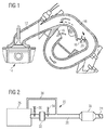
- Fig. 1 shows a schematic view of a switching intake manifold 10 in an internal combustion engine (not shown).
- the Switching intake pipe 10 leads pre-compressed air over the pipe section 12 in the schematically represented cylinder 14.
- the Motor control (not shown) a position for one Intake manifold flap 16 a.
- the intake flap 16 in shown in their open position, in the air over the Opening 18 and opening 20 enters the suction pipe 10.
- the open intake manifold flap 16 causes training a resonance of the charge air essentially only the shorter one Section of the suction pipe 10 downstream of the opening 20 is available. This will make the effective length of the Shortened intake manifold.
- the closed intake manifold flap delivers at low engine speeds 16 with the long intake manifold a higher air mass in the cylinder as the short intake manifold. At higher air mass this behavior turns around so that the short intake manifold provides a larger air mass than the long intake manifold. If the functionality of the intake manifold flap 16 is now disturbed, in which they permanently closed or opened, for example is the malfunction of the intake manifold flap noticeable at high or low engine speed. If the Intake manifold flap not switched at the predetermined engine speed is, this leads to a deviation of the open throttle valve sucked air mass against a value modeled by the motor controller.
- Fig. 2 shows a very schematic view of an exhaust system 22 with an exhaust flap 24.
- the internal combustion engine 26 outputs its exhaust gases via an exhaust pipe 28.
- the exhaust pipe 28 has, for example, an output signal a lambda probe 30 exhibiting a linear behavior, that are upstream of a catalyst 32 in the exhaust stream is provided. Subsequently, the exhaust gases in the catalyst 32 cleaned and again by a second lambda probe 34 measured. Downstream from the second lambda probe 34 is shown schematically an exhaust gas recirculation 36 Rear silencer 38 is schematically upstream of the Exhaust flap 24 shown.
- m_thr_mod P_thr ⁇ f (T_amb), where P_thr is the pressure in front of the throttle valve, T_amb is the ambient temperature and f (T_amb) is a function stored in the form of characteristic curves and / or data.
Abstract
Description
Die Erfindung betrifft Verfahren zur Erkennung einer Fehlfunktion einer Abgasklappeneinrichtung und/oder einer Saugrohrumschalteinrichtung.The invention relates to methods for detecting a malfunction an exhaust valve device and / or an intake manifold switching device.
Die Abgasklappeneinrichtung besitzt eine Abgasklappe zur Beeinflussung der Akustik in einem Abgassystem einer Brennkraftmaschine. Die Abgasklappeneinrichtung schaltet ansprechend auf Steuersignale einer Motorsteuerung die Abgasklappe in die geöffnete oder geschlossene Position. Die Abgasklappe wird bei niedrigen Drehzahlen, ungefähr bis 2500 U/min, in einer geschlossenen Stellung gebracht. In der geschlossenen Stellung der Abgasklappe werden die bei niedrigen Drehzahlen dominierenden, tieffrequenten Mündungsgeräusche drastisch reduziert. Erst bei einer höheren Drehzahl öffnet die Abgasklappe, da dann die Roll- und Fahrgeräusche überwiegen. Die Abgasklappe kann auch abhängig von einer Lastschwelle eingestellt werden. Ist die Abgasklappe bei hoher Drehzahl und Last, also einem hohen Luftmassenstrom in die Brennkraftmaschine, nicht geöffnet, so wird der Luftmassenstrom in die Zylinder durch eine erhöhte interne Abgasrückführung reduziert.The exhaust flap device has an exhaust flap for influencing the acoustics in an exhaust system of an internal combustion engine. The exhaust valve device switches responsively to control signals from an engine control system, the exhaust flap in the open or closed position. The exhaust flap is in at low speeds, approximately up to 2500 rpm brought into a closed position. In the closed The position of the exhaust flap is at low engine speeds dominant, low-frequency muzzle noises drastically reduced. The exhaust flap only opens at a higher speed, because then the rolling and driving noises predominate. The Exhaust flap can also be set depending on a load threshold become. Is the exhaust flap at high speed and Load, i.e. a high air mass flow into the internal combustion engine, not opened, the air mass flow is in the Cylinder reduced by increased internal exhaust gas recirculation.
Bei Motorsteuerungssystemen mit einer Saugrohrumschaltung wird zur Beeinflussung der maximalen Füllung eine Saugrohrklappe betätigt, die die Länge des Ansaugrohrs verändert. Wenn die Saugrohrklappe zur Saugrohrumschaltung bei niedriger Drehzahl nicht geschlossen ist, wird die Motorleistung bei voll geöffneter Drosselklappe wegen der fehlenden Resonanzladung reduziert. Mithin erfolgt lediglich ein reduzierter Luftmassenstrom in die Zylinder. Im stationären Zustand ist damit auch der Luftmassenstrom durch die Drosselklappe reduziert. In engine control systems with intake manifold changeover becomes an intake manifold flap to influence the maximum filling actuated, which changes the length of the intake pipe. If the intake manifold flap for intake manifold switching at low Speed is not closed, the engine power is at fully open throttle valve due to the lack of resonance charge reduced. As a result, there is only a reduced one Air mass flow into the cylinders. Is in steady state this also reduces the air mass flow through the throttle valve.
Es ist bekannt, sowohl bei der Saugrohrumschalteinrichtung als auch bei der Abgasklappeneinrichtung eine elektrische Diagnose, beispielsweise auf Kurzschluss oder Leitungsbruch, des jeweiligen Aktuators durchzuführen. Eine darüber hinausgehende Diagnose einer Fehlfunktion ist nicht bekannt.It is known both in the intake manifold switching device as well as an electrical diagnosis for the exhaust flap device, for example on short circuit or wire break, of the respective actuator. A further one Diagnosis of a malfunction is not known.
Der Erfindung liegt die Aufgabe zugrunde, ein Verfahren bereitzustellen, mit dem die Motorsteuerung feststellen kann, ob eine Abgasklappeneinrichtung und/oder eine Saugrohrumschalteinrichtung einwandfrei funktionieren.The invention has for its object to provide a method with which the engine control can determine whether an exhaust valve device and / or an intake manifold switching device work flawlessly.
Erfindungsgemäß wird die Aufgabe für eine Abgasklappeneinrichtung durch ein Verfahren nach Anspruch 1 gelöst.According to the invention, the task for an exhaust valve device solved by a method according to claim 1.
Das erfindungsgemäße Verfahren erkennt eine Fehlfunktion einer Abgasklappeneinrichtung. Die Abgasklappeneinrichtung besitzt eine Abgasklappe, die zur Beeinflussung der Akustik in einem Abgassystem ansprechend auf Steuersignale einer Motorsteuerung schließt oder öffnet. Vorzugsweise ist die Abgasklappe bei niedrigen Drehzahlen der Brennkraftmaschine, vorzugsweise bei weniger als ungefähr 2500 U/min, geschlossen, während sie bei höheren Drehzahlwerten geöffnet ist. Um eine Fehlfunktion an der Abgasklappe zu erkennen, misst ein Luftmassensensor die durch eine Drosselklappe tretende Luftmasse (m_thr_real), bei hoher Drehzahl. Bei hoher Drehzahl und/oder einem hohen Luftmassenstrom sollte bei einwandfreier Funktionsweise die Abgasklappe geöffnet sein. Die Motorsteuerung vergleicht die gemessene Luftmasse mit einem Modellwert für den Luftmassenstrom (m_thr_mod), der von der Umgebungstemperatur (T_amb) und dem Druck (P_thr) abhängt. Die Motorsteuerung vergleicht die beiden Werte für den Luftmassenstrom und erkennt mit Hilfe der Abweichung des gemessenen Wertes von den Modellwerten, ob die Abgasklappe geöffnet ist. Die Abweichung ist beispielsweise der Absolutbetrag der Differenzwerte. Ist die Abgasklappe bei hoher Drehzahl geschlossen, so wird über die interne Abgasrückführung der Luftmassenstrom durch die Drosselklappe in die Zylinder reduziert. Dieser Effekt wird erfindungsgemäß genutzt, um die Funktionsfähigkeit der Abgasklappe zu diagnostizieren.The method according to the invention detects a malfunction Exhaust flap means. The exhaust valve device has an exhaust flap, which is used to influence the acoustics in an exhaust system in response to control signals from an engine controller closes or opens. The exhaust flap is preferably at low engine speeds, preferably at less than about 2500 rpm, closed, while it is open at higher speed values. Around Detecting a malfunction on the exhaust flap is a measure Air mass sensor the air mass passing through a throttle valve (m_thr_real), at high speed. At high speed and / or a high air mass flow should be flawless Functionality, the exhaust flap must be open. The engine control compares the measured air mass with a model value for the air mass flow (m_thr_mod), which depends on the ambient temperature (T_amb) and the pressure (P_thr) depends. The engine control compares the two values for the air mass flow and recognizes with the help of the deviation of the measured Value of the model values, whether the exhaust flap is open. The deviation is, for example, the absolute amount of the difference values. If the exhaust flap is closed at high speed, the air mass flow is thus via the internal exhaust gas recirculation reduced by the throttle valve in the cylinders. This effect is used according to the invention to ensure the functionality diagnose the exhaust valve.
In einer bevorzugten Weiterführung erzeugt die Motorsteuerung ein Signal, das eine Fehlfunktion der Abgasklappeneinrichtung anzeigt, wenn die Abweichung einen Schwellenwert überschreitet. Aufgrund der Unsicherheit bei den modulierten Werten wird nicht jeder Abweichung zwischen gemessenem Wert und modelliertem Wert als eine Fehlfunktion erkannt. Vielmehr wird ein Schwellenwert definiert, den die Abweichung überschreiten muss, damit eine Fehlfunktion erkannt wird.In a preferred embodiment, the engine control generates a signal indicating a malfunction of the exhaust valve device indicates when the deviation exceeds a threshold. Due to the uncertainty in the modulated values not every difference between measured value and modeled Value recognized as a malfunction. Rather it will defines a threshold that the deviation will exceed must be so that a malfunction is recognized.
Eine besonders bevorzugte Überprüfung der Diagnose erfolgt, indem die Motorsteuerung nach einem Befehl zum Öffnen der Abgasklappe ein Signal zum Schließen der Abgasklappe erzeugt und an die Abgasklappeneinrichtung anlegt. Die Motorsteuerung erkennt hierbei eine Fehlfunktion der Abgasklappe lediglich dann, wenn die Abweichung nach dem Signal zum Schließen der Abgasklappe nicht zunimmt. Dadurch, dass das Signal der Motorsteuerung zum Schließen der Abgasklappe bei hohem angeforderten Luftstrom angelegt wird, müsste bei ordnungsgemäßem Betrieb die Abgasklappe sich schließen. Bei einem fehlerhaften Fall darf die Abweichung zwischen modelliertem Wert und gefühltem Wert nicht zunehmen. Hierbei ist vorzugsweise noch die Verzögerungszeit zu berücksichtigen, die bis zum stationär werden des Saugrohrdrucks verstreicht.A particularly preferred check of the diagnosis is made by the engine control after a command to open the exhaust flap generates a signal to close the exhaust flap and applies to the exhaust valve device. The engine control only recognizes a malfunction of the exhaust flap then when the deviation after the signal to close the Exhaust flap does not increase. In that the signal of the engine control to close the exhaust flap when the demand is high Airflow is created, should be done properly Operation the exhaust flap close. If there is a fault The difference between the modeled value and perceived value does not increase. Here is preferably still to take into account the delay time to the stationary the intake manifold pressure is passed.
Eine Fehlfunktion in der Abgasklappeneinrichtung ist in der Werkstatt überaus schwierig zu diagnostizieren, da für einen Fahrer des Fahrzeugs lediglich das Phänomen auftritt, dass bei hohen Drehzahlen die Brennkraftmaschine über das Gaspedal angeforderte Leistung nicht oder nicht schnell genug bereitstellt. Die Suche nach der Ursache dieses Verhaltens ist jedoch zeit- und kostenaufwendig. Bevorzugt zeigt daher die Motorsteuerung eine erkannte Fehlfunktion der Abgasklappeneinrichtung an und/oder speichert ein entsprechendes Signal für ein Diagnosesystem. Hierdurch ist bei einer Diagnose der Brennkraftmaschine in der Werkstatt eine Fehlfunktion der Abgasklappeneinrichtung schnell erkennbar und kann entsprechend behoben werden.A malfunction in the exhaust valve device is in the Workshop extremely difficult to diagnose because for one Drivers of the vehicle only experience the phenomenon that at high speeds, the engine via the accelerator pedal does not provide the requested service or does not provide it quickly enough. However, the search for the cause of this behavior is time and cost consuming. The engine control therefore preferably shows a detected malfunction of the exhaust valve device on and / or stores a corresponding signal for a diagnostic system. This makes the diagnosis Internal combustion engine in the workshop malfunction of the exhaust valve device quickly recognizable and can accordingly be resolved.
In einer bevorzugten Ausgestaltung des erfindungsgemäßen Verfahrens wird der modellierte Wert für den Luftmassenstrom bei weit geöffneter Drosselklappe als Produkt aus Druck und einer temperaturabhängigen Funktion bestimmt. Die Funktion mit ihren Funktionswerten ist hierbei bevorzugt in der Motorsteuerung abgelegt. Bei einer weniger weit geöffneten Drosselklappe kann zusätzlich die Stellung der Drosselklappe und das Druckverhältnis von Saugrohrdruck zu Druck vor der Drosselklappe berücksichtigt werden.In a preferred embodiment of the method according to the invention the modeled value for the air mass flow at throttle valve wide open as a product of pressure and one temperature-dependent function. The function with their Function values are preferred in the engine control stored. With a throttle valve that is less open can also the position of the throttle valve and Pressure ratio of intake manifold pressure to pressure in front of the throttle valve be taken into account.
Die erfindungsgemäße Aufgabe wird ebenfalls durch ein Verfahren nach Anspruch 7 gelöst.The object of the invention is also achieved by a method solved according to claim 7.
Das Verfahren betrifft die Erkennung einer Fehlfunktion einer Saugrohrschalteinrichtung, die eine Saugrohrklappe zur Beeinflussung der maximalen Befüllung der Brennkraftmaschine in einem Ansaugtrakt aufweist und die ansprechend auf Steuersignale einer Motorsteuerung umschaltet. Das Verfahren betrifft eine Diagnose bei einer Drosselklappenöffnung weiter als ein vorbestimmter Schwellenwert. Erfindungsgemäß wird bei dem Verfahren in einem ersten Schritt die durch eine Drosselklappe dringende Luftmasse (m_thr_real) von einem Luftmassensensor gemessen. Die Motorsteuerung vergleicht bei niedriger Drehzahl die gemessene Luftmasse mit einem Modellwert für den Luftmassenstrom (m_thr_mod), der von einer Umgebungstemperatur (T_amb) und einem Druck (P_thr) abhängt. Die Motorsteuerung erkennt mit Hilfe der Abweichung der Modellwerte von den gefühlten Werten, ob die Saugrohrklappe geschlossen oder geöffnet ist. Ist die Saugrohrklappe bei niedriger Drehzahl geöffnet, so ist der Luftmassenstrom in die Zylinder aufgrund der fehlenden Resonanzladung nicht ausreichend. Diese Abweichung des Luftmassenstroms wird bei dem Vergleich zwischen gefühltem Luftmassenstrom und dem Modellwert festgestellt.The method relates to the detection of a malfunction Intake manifold switching device, which an intake manifold flap for influencing the maximum filling of the internal combustion engine in has an intake tract and which are responsive to control signals a motor control switches. The procedure concerns a diagnosis of a throttle valve opening more than one predetermined threshold. According to the invention Process in a first step through a throttle valve Urgent air mass (m_thr_real) from an air mass sensor measured. The engine control compares at lower Speed the measured air mass with a model value for the Air mass flow (m_thr_mod) that depends on an ambient temperature (T_amb) and a pressure (P_thr) depends. The engine control recognizes with the help of the deviation of the model values from the perceived values whether the intake manifold flap is closed or open is. If the intake manifold flap is open at low speed, so the air mass flow into the cylinders is due insufficient resonance charge. This deviation of the air mass flow is used in the comparison between felt air mass flow and the model value.
Auch bei der Saugrohrumschaltung wird eine Fehlfunktion erst erkannt, wenn die Abweichung zwischen gefühltem und moduliertem Wert eine Mindestgrenze überschreitet.A malfunction only occurs when the intake manifold is switched over detected when the deviation between sensed and modulated Value exceeds a minimum limit.
In einer bevorzugten Ausgestaltung des Verfahrens wird das Ergebnis aus dem Vergleich überprüft, indem die Motorsteuerung ein Signal zum Öffnen der Saugrohrklappe bei niedriger Drehzahl und weit geöffneter Drosselklappe erzeugt. Wenn die Abweichung zwischen dem modellierten Luftmassenstrom und dem gefühlten Lustmassenstrom nachfolgend nicht weiter zunimmt, wird gefolgert, dass das Saugrohr nunmehr geöffnet ist und keine Fehlfunktion vorliegt. Bevorzugt wird hierbei eine vorbestimmte Verzögerungszeitdauer abgewartet, bis sich der Saugrohrdruck stationär ausgebildet hat.In a preferred embodiment of the method, the Result from the comparison checked by the engine control a signal to open the intake manifold flap at low Speed and wide open throttle valve generated. If the Deviation between the modeled air mass flow and the perceived lust mass flow does not subsequently increase, it is concluded that the intake manifold is now open and there is no malfunction. A predetermined one is preferred Delay period waited until the Intake manifold pressure is stationary.
Bevorzugt zeigt die Motorsteuerung eine erkannte Fehlfunktion auch für die Umschaltklappeneinrichtung an und/oder speichert ein entsprechendes Signal für ein Diagnosesystem. Auch für die Diagnose der Umschaltklappeneinrichtung kann der modellierte Wert für den Luftmassenstrom als Produkt aus Druck und dem Wert einer temperaturabhängigen Funktion bestimmt werden, da eine weit geöffnete Drosselklappe vorliegt. Ansonsten müssen die Drosselklappenöffnung und das Druckverhältnis zwischen Saugrohrdruck und Druck vor der Drosselklappe im Modell zusätzlich mit berücksichtigt werden.The engine control preferably shows a detected malfunction also for the switching flap device and / or stores a corresponding signal for a diagnostic system. Also for the diagnosis of the switching flap device can be modeled Value for the air mass flow as a product of pressure and the value of a temperature-dependent function can be determined, because there is a wide open throttle valve. Otherwise must the throttle valve opening and the pressure ratio between Intake manifold pressure and pressure in front of the throttle valve in the model are also taken into account.
Die erfindungsgemäßen Verfahren werden anhand der nachfolgenden Figuren näher erläutert. Es zeigt:
- Fig. 1
- eine Schaltsaugrohranordnung und
- Fig. 2
- eine schematische Ansicht eines Abgassystems mit einer Abgasklappe.
- Fig. 1
- a switching intake manifold arrangement and
- Fig. 2
- a schematic view of an exhaust system with an exhaust flap.
Fig. 1 zeigt eine schematische Ansicht eines Schaltsaugrohres
10 in einer Brennkraftmaschine (nicht dargestellt). Das
Schaltsaugrohr 10 führt vorverdichtete Luft über den Rohrabschnitt
12 in den schematisch dargestellten Zylinder 14.Fig. 1 shows a schematic view of a switching
Abhängig von der Drehzahl der Brennkraftmaschine stellt die
Motorsteuerung (nicht dargestellt) eine Position für eine
Saugrohrklappe 16 ein. In Fig. 1 ist die Ansaugklappe 16 in
ihrer geöffneten Position dargestellt, in der Luft über die
Öffnung 18 und die Öffnung 20 in das Saugrohr 10 eintritt.
Die geöffnete Saugrohrklappe 16 bewirkt, dass zur Ausbildung
einer Resonanz der Ladeluft im wesentlichen nur der kürzere
Abschnitt des Saugrohrs 10 stromabwärts von der Öffnung 20
zur Verfügung steht. Hierdurch wird die wirksame Länge des
Saugrohres verkürzt.Depending on the speed of the internal combustion engine, the
Motor control (not shown) a position for one
Intake manifold flap 16 a. In Fig. 1, the
Bei niedrigen Motordrehzahlen liefert die geschlossene Saugrohrklappe
16 mit dem langen Saugrohr eine höhere Luftmasse
im Zylinder als das kurze Saugrohr. Bei höherer Luftmasse
dreht sich dieses Verhalten genau um, so dass das kurze Saugrohr
eine größere Luftmasse als das lange Saugrohr liefert.
Ist die Funktionalität der Saugrohrklappe 16 nun gestört, in
dem sie beispielsweise dauerhaft geschlossen oder geöffnet
ist, so macht sich die Funktionsstörung der Saugrohrklappe
bei hoher bzw. niedriger Motordrehzahl bemerkbar. Wenn die
Saugrohrklappe nicht bei der vorbestimmten Motordrehzahl umgeschaltet
wird, so führt dies zu einer Abweichung der bei
geöffneter Drosselklappe angesaugten Luftmasse gegenüber einem
von der Motorsteuerung modellierten Wert.The closed intake manifold flap delivers at low engine speeds
16 with the long intake manifold a higher air mass
in the cylinder as the short intake manifold. At higher air mass
this behavior turns around so that the short intake manifold
provides a larger air mass than the long intake manifold.
If the functionality of the
Fig. 2 zeigt in einer sehr schematischen Ansicht ein Abgassystem
22 mit einer Abgasklappe 24. Die Brennkraftmaschine 26
gibt ihre Abgase über eine Abgasleitung 28 aus. Die Abgasleitung
28 besitzt beispielsweise eine bezüglich ihres Ausgangssignals
ein lineares Verhalten aufweisende Lambdasonde 30,
die stromaufwärts von einem Katalysator 32 in dem Abgasstrom
vorgesehen ist. Nachfolgend werden die Abgase in dem Katalysator
32 gereinigt und durch eine zweite Lambdasonde 34 erneut
gemessen. Stromabwärts von der zweiten Lambdasonde 34
ist schematisch eingezeichnet eine Abgasrückführung 36. Der
Nachschalldämpfer 38 ist schematisch stromaufwärts von der
Abgasklappe 24 dargestellt.Fig. 2 shows a very schematic view of an
Bei niedrigen Motordrehzahlen, vorzugsweise unter 2.500
U/min, überwiegen die tieffrequenten Mündungsgeräusche, diese
werden durch die geschlossene Abgasklappe 24 drastisch reduziert.
Beispielmessungen haben ergeben, dass eine Reduzierung
um ungefähr 10 dB erzielt werden kann. Bei höheren Drehzahlen
überwiegen die Roll- und Fahrgeräusche, so dass durch Einschließen
der Abgasklappe 24 keine Geräuschreduzierung erzielt
werden kann.At low engine speeds, preferably below 2,500
Rpm, the low-frequency muzzle noises outweigh these
are drastically reduced by the
Ist bei hohen Drehzahlen die Abgasklappe 24 geschlossen, so
wird über die erhöhte Abgasrückführung 36 der Luftmassenstrom
zu den Zylindern reduziert. Diese Reduktion des Luftmassenstroms
in die Zylinder wird bei geöffneter Drosselklappe und
hoher Drehzahl durch das erfindungsgemäße Verfahren erkannt,
indem der gemessene Luftmassenstrom von dem modellierten
Luftmassenstrom abweicht.If the
Der modellierte Luftmassenstrom (m_thr_mod) wird bei weit geöffneter
Drosselklappe durch die Motorsteuerung wie folgt berechnet:
Claims (14)
gekennzeichnet durch folgende Verfahrensschritte:
characterized by the following process steps:
dadurch gekennzeichnet, dass die Motorsteuerung ein Signal erzeugt, das eine Fehlfunktion der Abgasklappeneinrichtung anzeigt, wenn die Abweichung einen Schwellenwert überschreitet.Method according to claim 1,
characterized in that the engine controller generates a signal indicating a malfunction of the exhaust valve device when the deviation exceeds a threshold value.
dadurch gekennzeichnet, dass die Motorsteuerung bei vorherigem Befehl zum Öffnen der Abgasklappe (24) ein Signal zum Schließen der Abgasklappe (24) erzeugt, dieses an die Abgasklappeneinrichtung anlegt und die Motorsteuerung eine Fehlfunktion der Abgasklappe (24) erkennt, wenn die Abweichung nach dem Signal zum Schließen der Abgasklappe (24) nicht zunimmt.Method according to claim 1 or 2,
characterized in that the engine control generates a signal to close the exhaust flap (24) upon a previous command to open the exhaust flap (24), applies this to the exhaust flap device and the engine control recognizes a malfunction of the exhaust flap (24) if the deviation after the signal does not increase to close the exhaust flap (24).
dadurch gekennzeichnet, dass die Erkennung der Fehlfunktion erfolgt, nachdem eine vorbestimmte Zeitdauer seit dem Signal zum Schließen der Abgasklappe (24) verstrichen ist.Method according to claim 3,
characterized in that the malfunction is detected after a predetermined period of time has elapsed since the signal to close the exhaust valve (24).
dadurch gekennzeichnet, dass die Motorsteuerung eine bekannte Fehlfunktion der Abgasklappeneinrichtung anzeigt und/oder ein entsprechendes Signal für ein Diagnosesystem der Motorsteuerung speichert.Method according to one of claims 1 to 4,
characterized in that the engine control indicates a known malfunction of the exhaust valve device and / or stores a corresponding signal for a diagnostic system of the engine control.
dadurch gekennzeichnet, dass bei weit geöffneter Drosselklappe der modellierte Wert für den Luftmassenstrom (m_thr_mod) als Produkt aus dem Druck und einer temperaturabhängigen Funktion berechnet wird.Method according to one of claims 1 to 5,
characterized in that the modeled value for the air mass flow (m_thr_mod) is calculated as a product of the pressure and a temperature-dependent function when the throttle valve is wide open.
dadurch gekennzeichnet, dass der modellierte Wert für den Luftmassenstrom bei einer nicht weit geöffneten Drosselklappe von der Stellung der Drosselklappe und dem Druckverhältnis zwischen Saugrohrdruck und Druck vor der Drosselklappe abhängt.Method according to claim 6,
characterized in that the modeled value for the air mass flow depends on the position of the throttle valve and the pressure ratio between intake manifold pressure and pressure in front of the throttle valve when the throttle valve is not wide open.
gekennzeichnet durch folgende Verfahrensschritte:
characterized by the following process steps:
dadurch gekennzeichnet, dass die Motorsteuerung ein Signal erzeugt, das eine Fehlfunktion der Saugrohrumschalteinrichtung anzeigt, wenn die Abweichung einen Schwellenwert überschreitet.A method according to claim 8,
characterized in that the engine controller generates a signal indicating a malfunction of the intake manifold switching device when the deviation exceeds a threshold value.
dadurch gekennzeichnet, dass die Motorsteuerung bei niedriger Drehzahl und einem vorherigen Befehl zum Schließen der Saugrohrklappe (16) ein Signal zum Öffnen der Saugrohrklappe (16) erzeugt, dieses an die Umschalteinrichtung anlegt und die Motorsteuerung eine Fehlfunktion der Abgasklappeneinrichtung erkennt, wenn die Abweichung nach dem Signal zum Öffnen der Saugrohrklappe (16) nicht zunimmt.Method according to claim 8 or 9,
characterized in that the engine control at low speed and a previous command to close the intake manifold flap (16) generates a signal to open the intake manifold flap (16), applies this to the switching device and the engine control system detects a malfunction of the exhaust flap device if the deviation after Signal to open the intake manifold flap (16) does not increase.
dadurch gekennzeichnet, dass die Erkennung der Fehlfunktion erfolgt, nachdem eine vorbestimmte Zeitdauer seit dem Signal zum Öffnen der Saugrohrklappe (16) verstrichen ist.A method according to claim 10,
characterized in that the malfunction is detected after a predetermined period of time has passed since the signal to open the intake manifold flap (16).
dadurch gekennzeichnet, dass die Motorsteuerung eine erkannte Fehlfunktion anzeigt und/oder ein entsprechendes Signal für ein Diagnosesystem speichert.Method according to one of claims 8 to 11,
characterized in that the engine control indicates a detected malfunction and / or stores a corresponding signal for a diagnostic system.
dadurch gekennzeichnet, dass der modellierte Wert für den Luftmassenstrom bei weit geöffneter Drosselklappe als Produkt aus Druck und Wert einer temperaturabhängigen Funktion berechnet wird.Method according to one of claims 8 to 12,
characterized in that the modeled value for the air mass flow is calculated with the throttle valve wide open as the product of pressure and value of a temperature-dependent function.
dadurch gekennzeichnet, dass der modellierte Wert für den Luftmassenstrom zusätzlich von der Stellung der Drosselklappe und dem Druckverhältnis des Saugrohrdrucks und dem Druck vor der Drosselklappe abhängt, falls die Drosselklappe nicht weit geöffnet ist.A method according to claim 13,
characterized in that the modeled value for the air mass flow additionally depends on the position of the throttle valve and the pressure ratio of the intake manifold pressure and the pressure in front of the throttle valve if the throttle valve is not opened wide.
Applications Claiming Priority (2)
| Application Number | Priority Date | Filing Date | Title |
|---|---|---|---|
| DE10144674A DE10144674B4 (en) | 2001-09-11 | 2001-09-11 | Method for detecting a malfunction in an exhaust gas flap device and / or an intake manifold changeover device |
| DE10144674 | 2001-09-11 |
Publications (2)
| Publication Number | Publication Date |
|---|---|
| EP1291508A2 true EP1291508A2 (en) | 2003-03-12 |
| EP1291508A3 EP1291508A3 (en) | 2008-03-12 |
Family
ID=7698592
Family Applications (1)
| Application Number | Title | Priority Date | Filing Date |
|---|---|---|---|
| EP02102264A Withdrawn EP1291508A3 (en) | 2001-09-11 | 2002-09-02 | Method for detecting malfunctioning in the exhaust flap valve and/or in the intake conduit valve |
Country Status (2)
| Country | Link |
|---|---|
| EP (1) | EP1291508A3 (en) |
| DE (1) | DE10144674B4 (en) |
Cited By (3)
| Publication number | Priority date | Publication date | Assignee | Title |
|---|---|---|---|---|
| EP1462635A1 (en) * | 2003-03-26 | 2004-09-29 | Mitsubishi Jidosha Kogyo Kabushiki Kaisha | Failure diagnostic system for exhaust pressure increasing device |
| FR2858655A1 (en) * | 2003-08-06 | 2005-02-11 | Honda Motor Co Ltd | DEVICE FOR CONTROLLING THE ENGINE PERFORMANCE |
| EP1936146A2 (en) * | 2006-12-23 | 2008-06-25 | Dr. Ing. h.c. F. Porsche Aktiengesellschaft | Method and control device for monitoring the inlet manifold length adjustment for a combustion engine |
Families Citing this family (7)
| Publication number | Priority date | Publication date | Assignee | Title |
|---|---|---|---|---|
| DE10346734B3 (en) | 2003-10-08 | 2005-04-21 | Bayerische Motoren Werke Ag | Method for fault diagnosis with a variable intake manifold in the intake system of an internal combustion engine |
| DE102008028722B3 (en) * | 2008-06-17 | 2010-02-11 | Continental Automotive Gmbh | Method for analyzing plausible errors by monitoring position acknowledgement of actuator controlled by controller, involves sending signal for position acknowledgement of sensor |
| US8095292B2 (en) * | 2009-05-22 | 2012-01-10 | GM Global Technology Operations LLC | Variable intake manifold diagnostic systems and methods |
| DE102012213389B4 (en) | 2012-07-31 | 2014-07-10 | Continental Automotive Gmbh | Device for operating an internal combustion engine |
| DE102017129234A1 (en) * | 2017-11-06 | 2019-05-09 | Eberspächer Exhaust Technology GmbH & Co. KG | Method and device for analyzing the acoustic behavior of an exhaust flap |
| DE102018128191A1 (en) * | 2018-11-12 | 2020-05-14 | Volkswagen Aktiengesellschaft | Method for setting an exhaust gas retention and / or an internal EGR by means of an exhaust gas flap in the operation of an internal combustion engine |
| DE102021212114A1 (en) | 2021-10-27 | 2023-04-27 | Robert Bosch Gesellschaft mit beschränkter Haftung | Method and device for checking the plausibility of a position of an exhaust flap in an engine system with an internal combustion engine |
Citations (3)
| Publication number | Priority date | Publication date | Assignee | Title |
|---|---|---|---|---|
| WO1991013246A1 (en) * | 1990-02-26 | 1991-09-05 | Robert Bosch Gmbh | Diagnostic process for checking regulation elements for the control of internal-combustion engines |
| DE19727669A1 (en) * | 1997-06-30 | 1999-01-07 | Bosch Gmbh Robert | Monitoring function throttle flap of IC engine |
| DE19944539A1 (en) * | 1999-09-17 | 2001-03-22 | Daimler Chrysler Ag | IC engine with exhaust gas flap between catalyser and exhaust muffler has engine control unit provided with safety device comparing actual air flowrate with required value provided by stored characteristic |
Family Cites Families (2)
| Publication number | Priority date | Publication date | Assignee | Title |
|---|---|---|---|---|
| JP3053703B2 (en) * | 1992-08-25 | 2000-06-19 | 三菱電機株式会社 | Secondary air control device |
| DE4343639A1 (en) * | 1993-12-21 | 1995-06-22 | Bosch Gmbh Robert | Method for monitoring a secondary air system in connection with the exhaust system of a motor vehicle |
-
2001
- 2001-09-11 DE DE10144674A patent/DE10144674B4/en not_active Expired - Fee Related
-
2002
- 2002-09-02 EP EP02102264A patent/EP1291508A3/en not_active Withdrawn
Patent Citations (3)
| Publication number | Priority date | Publication date | Assignee | Title |
|---|---|---|---|---|
| WO1991013246A1 (en) * | 1990-02-26 | 1991-09-05 | Robert Bosch Gmbh | Diagnostic process for checking regulation elements for the control of internal-combustion engines |
| DE19727669A1 (en) * | 1997-06-30 | 1999-01-07 | Bosch Gmbh Robert | Monitoring function throttle flap of IC engine |
| DE19944539A1 (en) * | 1999-09-17 | 2001-03-22 | Daimler Chrysler Ag | IC engine with exhaust gas flap between catalyser and exhaust muffler has engine control unit provided with safety device comparing actual air flowrate with required value provided by stored characteristic |
Cited By (4)
| Publication number | Priority date | Publication date | Assignee | Title |
|---|---|---|---|---|
| EP1462635A1 (en) * | 2003-03-26 | 2004-09-29 | Mitsubishi Jidosha Kogyo Kabushiki Kaisha | Failure diagnostic system for exhaust pressure increasing device |
| FR2858655A1 (en) * | 2003-08-06 | 2005-02-11 | Honda Motor Co Ltd | DEVICE FOR CONTROLLING THE ENGINE PERFORMANCE |
| EP1936146A2 (en) * | 2006-12-23 | 2008-06-25 | Dr. Ing. h.c. F. Porsche Aktiengesellschaft | Method and control device for monitoring the inlet manifold length adjustment for a combustion engine |
| EP1936146A3 (en) * | 2006-12-23 | 2014-07-02 | Dr. Ing. h.c. F. Porsche AG | Method and control device for monitoring the inlet manifold length adjustment for a combustion engine |
Also Published As
| Publication number | Publication date |
|---|---|
| DE10144674B4 (en) | 2004-06-03 |
| EP1291508A3 (en) | 2008-03-12 |
| DE10144674A1 (en) | 2003-04-03 |
Similar Documents
| Publication | Publication Date | Title |
|---|---|---|
| DE102007000892B4 (en) | Apparatus for diagnosing abnormal operation of an apparatus for detecting a pressure difference for an engine exhaust system | |
| EP2616655B1 (en) | Method and device for diagnosing crankcase ventilation of internal combustion engines | |
| DE102008027762B3 (en) | Method and device for diagnosing an intake tract of an internal combustion engine | |
| DE102014209840A1 (en) | Method and device for diagnosing a particulate filter | |
| WO2018036809A1 (en) | Method and apparatus for checking the plausibility of the functioning of a crankcase breather system | |
| WO2008142058A2 (en) | Diagnostic method and device for diagnosing an intake system of an internal combustion engine | |
| DE102005027565A1 (en) | Method for fault diagnosis of an ambient pressure sensor and an intake manifold pressure sensor | |
| DE102015007513B4 (en) | Method for detecting leaks in a crankcase ventilation system | |
| DE102008001099A1 (en) | Method and device for fault diagnosis in a motor system with variable valve control | |
| WO2018177897A1 (en) | Method and computer program product for diagnosing a particle filter | |
| DE102014210207A1 (en) | Control device and control method for internal combustion engine | |
| DE102007062794A1 (en) | Exhaust gas section's leakage testing method for combustion engine, involves identifying leakage in exhaust gas section depending on measured value, which indicates strength of relative pressure changes | |
| DE102008005958B4 (en) | Method and device for identifying a faulty pressure sensor in an intake tract of an internal combustion engine | |
| EP1711703B1 (en) | Method for adapting a measured value of an air mass sensor | |
| EP1291508A2 (en) | Method for detecting malfunctioning in the exhaust flap valve and/or in the intake conduit valve | |
| DE102005034270A1 (en) | Method for diagnosing a differential pressure sensor arranged in an exhaust gas region of a combustion engine comprises evaluating the dynamic behavior of a differential pressure signal as a result of a change in exhaust gas pressure | |
| WO2019120904A1 (en) | Method and device for determining the degree of fouling of an air filter of an internal combustion engine | |
| WO2002012702A1 (en) | Method for the functional diagnosis of an exhaust recycling system on an internal combustion engine | |
| EP1242739B1 (en) | Method for detecting malfunctioning in a sensor | |
| DE102005045857B3 (en) | Ambient pressure finding process for engine involves finding air cleaner pressure, opening throttle valve, setting camshaft and detecting induction pressure | |
| EP1609970B1 (en) | Method and device to operate an internal combustion engine | |
| DE102008054764A1 (en) | Method for diagnosing ambient air-pulsed valve of charging device of internal combustion engine, involves determining information about operability of valve based on switching condition determined by modeling | |
| DE102007052576B4 (en) | Diagnostic method for detecting errors in pressure sensor-based boost pressure control of an exhaust gas turbocharger of an internal combustion engine | |
| DE102005012946A1 (en) | Method for operating internal combustion (IC) engine e.g. gasoline or diesel engine, for vehicle, involves producing model for engine parameters e.g. load pressure, air mass flow rate, based on compressor speed | |
| EP1630383B1 (en) | Method for the functional diagnosis of a charge moving flap |
Legal Events
| Date | Code | Title | Description |
|---|---|---|---|
| PUAI | Public reference made under article 153(3) epc to a published international application that has entered the european phase |
Free format text: ORIGINAL CODE: 0009012 |
|
| AK | Designated contracting states |
Kind code of ref document: A2 Designated state(s): AT BE BG CH CY CZ DE DK EE ES FI FR GB GR IE IT LI LU MC NL PT SE SK TR Designated state(s): AT BE BG CH CY CZ DE DK EE ES FI FR GB GR IE IT LI LU MC NL PT SE SK TR |
|
| AX | Request for extension of the european patent |
Extension state: AL LT LV MK RO SI |
|
| PUAL | Search report despatched |
Free format text: ORIGINAL CODE: 0009013 |
|
| AK | Designated contracting states |
Kind code of ref document: A3 Designated state(s): AT BE BG CH CY CZ DE DK EE ES FI FR GB GR IE IT LI LU MC NL PT SE SK TR |
|
| AX | Request for extension of the european patent |
Extension state: AL LT LV MK RO SI |
|
| RAP1 | Party data changed (applicant data changed or rights of an application transferred) |
Owner name: CONTINENTAL AUTOMOTIVE GMBH |
|
| AKX | Designation fees paid | ||
| STAA | Information on the status of an ep patent application or granted ep patent |
Free format text: STATUS: THE APPLICATION IS DEEMED TO BE WITHDRAWN |
|
| 18D | Application deemed to be withdrawn |
Effective date: 20080913 |
|
| REG | Reference to a national code |
Ref country code: DE Ref legal event code: 8566 |